1
IronHorse® Worm Gearbox User Manual
IH-WG-USER-M-WO
3rd Edition
BLANK
PAGE
IronHorse® Worm Gearbox User Manual . . . . . . . . . . . . . .3rd Edition – 10/24/2014
WARNING Thank you for purchasing automation equipment from Automationdirect.com®, doing business as,
AutomationDirect. We want your new automation equipment to operate safely. Anyone who installs or
uses this equipment should read this publication (and any other relevant publications) before installing or
operating the equipment.
To minimize the risk of potential safety problems, you should follow all applicable local and national codes
that regulate the installation and operation of your equipment. These codes vary from area to area and
usually change with time. It is your responsibility to determine which codes should be followed, and to
verify that the equipment, installation, and operation is in compliance with the latest revision of these
codes.
At a minimum, you should follow all applicable sections of the National Fire Code, National Electrical
Code, and the codes of the National Electrical Manufacturer's Association (NEMA). There may be local
regulatory or government offices that can also help determine which codes and standards are necessary for
safe installation and operation.
Equipment damage or serious injury to personnel can result from the failure to follow all applicable codes
and standards. We do not guarantee the products described in this publication are suitable for your
particular application, nor do we assume any responsibility for your product design, installation, or
operation.
Our products are not fault-tolerant and are not designed, manufactured or intended for use or resale as online control equipment in hazardous environments requiring fail-safe performance, such as in the
operation of nuclear facilities, aircraft navigation or communication systems, air traffic control, direct life
support machines, or weapons systems, in which the failure of the product could lead directly to death,
personal injury, or severe physical or environmental damage ("High Risk Activities"). AutomationDirect
specifically disclaims any expressed or implied warranty of fitness for High Risk Activities.
For additional warranty and safety information, see the Terms and Conditions section of our catalog. If
you have any questions concerning the installation or operation of this equipment, or if you need
additional information, please call us at 770-844-4200.
This publication is based on information that was available at the time it was printed. At
AutomationDirect we constantly strive to improve our products and services, so we reserve the right to
make changes to the products and/or publications at any time without notice and without any obligation.
This publication may also discuss features that may not be available in certain revisions of the product.
Trademarks
This publication may contain references to products produced and/or offered by other companies. The
product and company names may be trademarked and are the sole property of their respective owners.
AutomationDirect disclaims any proprietary interest in the marks and names of others.
Copyright 2008, 2009, 2014, Automationdirect.com® Incorporated
All Rights Reserved
No part of this manual shall be copied, reproduced, or transmitted in any way without the prior, written
consent of Automationdirect.com® Incorporated. AutomationDirect retains the exclusive rights to all
information included in this document.
3rd Edition – 10/24/2014 . . . . . . . . . . . . . . .IronHorse® Worm Gearbox User Manual
W–1
AVERTISSEMENT Nous vous remercions d'avoir acheté l'équipement d'automatisation de Automationdirect.com®, en faisant des
affaires comme, AutomationDirect. Nous tenons à ce que votre nouvel équipement d'automatisation fonctionne en
toute sécurité. Toute personne qui installe ou utilise cet équipement doit lire la présente publication (et toutes les
autres publications pertinentes) avant de l'installer ou de l'utiliser.
Afin de réduire au minimum le risque d'éventuels problèmes de sécurité, vous devez respecter tous les codes locaux et
nationaux applicables régissant l'installation et le fonctionnement de votre équipement. Ces codes diffèrent d'une
région à l'autre et, habituellement, évoluent au fil du temps. Il vous incombe de déterminer les codes à respecter et
de vous assurer que l'équipement, l'installation et le fonctionnement sont conformes aux exigences de la version la
plus récente de ces codes.
Vous devez, à tout le moins, respecter toutes les sections applicables du Code national de prévention des incendies,
du Code national de l'électricité et des codes de la National Electrical Manufacturer's Association (NEMA). Des
organismes de réglementation ou des services gouvernementaux locaux peuvent également vous aider à déterminer
les codes ainsi que les normes à respecter pour assurer une installation et un fonctionnement sûrs.
L'omission de respecter la totalité des codes et des normes applicables peut entraîner des dommages à l'équipement
ou causer de graves blessures au personnel. Nous ne garantissons pas que les produits décrits dans cette publication
conviennent à votre application particulière et nous n'assumons aucune responsabilité à l'égard de la conception, de
l'installation ou du fonctionnement de votre produit.
Nos produits ne sont pas insensibles aux défaillances et ne sont ni conçus ni fabriqués pour l'utilisation ou la revente
en tant qu'équipement de commande en ligne dans des environnements dangereux nécessitant une sécurité absolue,
par exemple, l'exploitation d'installations nucléaires, les systèmes de navigation aérienne ou de communication, le
contrôle de la circulation aérienne, les équipements de survie ou les systèmes d'armes, pour lesquels la défaillance du
produit peut provoquer la mort, des blessures corporelles ou de graves dommages matériels ou environnementaux
(«activités à risque élevé»). La société AutomationDirect nie toute garantie expresse ou implicite d'aptitude à
l'emploi en ce qui a trait aux activités à risque élevé.
Pour des renseignements additionnels touchant la garantie et la sécurité, veuillez consulter la section Modalités et
conditions de notre documentation. Si vous avez des questions au sujet de l'installation ou du fonctionnement de cet
équipement, ou encore si vous avez besoin de renseignements supplémentaires, n'hésitez pas à nous téléphoner au
770-844-4200.
Cette publication s'appuie sur l'information qui était disponible au moment de l'impression. À la société
AutomationDirect, nous nous efforçons constamment d'améliorer nos produits et services. C'est pourquoi nous
nous réservons le droit d'apporter des modifications aux produits ou aux publications en tout temps, sans préavis ni
quelque obligation que ce soit. La présente publication peut aussi porter sur des caractéristiques susceptibles de ne
pas être offertes dans certaines versions révisées du produit.
Marques de commerce
La présente publication peut contenir des références à des produits fabriqués ou offerts par d'autres entreprises. Les
désignations des produits et des entreprises peuvent être des marques de commerce et appartiennent exclusivement à
leurs propriétaires respectifs. AutomationDirect nie tout intérêt dans les autres marques et désignations.
Copyright 2008, 2009, 2014, Automationdirect.com® Incorporated
Tous droits réservés
Nulle partie de ce manuel ne doit être copiée, reproduite ou transmise de quelque façon que ce soit sans le
consentement préalable écrit de la société Automationdirect.com® Incorporated. AutomationDirect conserve les
droits exclusifs à l'égard de tous les renseignements contenus dans le présent document.
W–2
IronHorse® Worm Gearbox User Manual . . . . . . . . . . . . . .3rd Edition – 10/24/2014
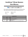
IRONHORSE® WORM GEARBOX
USER MANUAL
Please include the Manual Number and the Manual Issue, both shown below,
when communicating with Technical Support regarding this publication.
Manual Number:
IH-WG-User-M-WO
Issue:
3rd Edition
Issue Date:
10/24/2014
Publication History
Issue
Date
First Edition
1st Ed, Rev A
Second Edition
06/2008
06/2008
04/2009
Third Edition
10/2014
Description of Changes
Original Issue
Gearbox mounting orientation (Chapter 2)
Added cast-iron hollow-bore gearboxes
Renamed User Manual (was WG-User-M-WO)
Added aluminum gearboxes
Rearranged chapters
Revised output shaft dimensions for cast-iron solid-shaft gearboxes (Chapter 2)
3rd Edition – 10/24/2014 . . . . . . . . . . . . . . .IronHorse® Worm Gearbox User Manual
H–1
Publication History
H–2
IronHorse® Worm Gearbox User Manual . . . . . . . . . . . . . .3rd Edition – 10/24/2014
IRONHORSE® WORM GEARBOX
USER MANUAL TABLE OF CONTENTS
IronHorse® Worm Gearbox User Manual Contents
WARNING . . . . . . . . . . . . . . . . . . . . . . . . . . . . . . . . . . . . . . . . . . . . . . . . . . . . . . . .W–1
Trademarks . . . . . . . . . . . . . . . . . . . . . . . . . . . . . . . . . . . . . . . . . . . . . . . . . . . . . . .W–1
AVERTISSEMENT . . . . . . . . . . . . . . . . . . . . . . . . . . . . . . . . . . . . . . . . . . . . . . . . . . .W–2
Marques de commerce . . . . . . . . . . . . . . . . . . . . . . . . . . . . . . . . . . . . . . . . . . . . . .W–2
User Manual Publication History . . . . . . . . . . . . . . . . . . . . . . . . . . . . .H–1
Chapter 1: Getting Started . . . . . . . . . . . . . . . . . . . . . . . . . . . . . . . . .1–1
Manual Overview . . . . . . . . . . . . . . . . . . . . . . . . . . . . . . . . . . . . . . . . . . . . . . . . . . .1–2
Overview of This Publication . . . . . . . . . . . . . . . . . . . . . . . . . . . . . . . . . . . . . . . . . .1–2
Who Should Read This Manual . . . . . . . . . . . . . . . . . . . . . . . . . . . . . . . . . . . . . . . .1–2
Technical Support . . . . . . . . . . . . . . . . . . . . . . . . . . . . . . . . . . . . . . . . . . . . . . . . . .1–2
Special Symbols . . . . . . . . . . . . . . . . . . . . . . . . . . . . . . . . . . . . . . . . . . . . . . . . . . . .1–2
IronHorse® Worm Gearbox Introduction . . . . . . . . . . . . . . . . . . . . . . . . . . . . . . . . .1–3
Purpose of Worm Gearboxes . . . . . . . . . . . . . . . . . . . . . . . . . . . . . . . . . . . . . . . . . .1–3
Package Contents . . . . . . . . . . . . . . . . . . . . . . . . . . . . . . . . . . . . . . . . . . . . . . . . . .1–3
Part Number Explanation . . . . . . . . . . . . . . . . . . . . . . . . . . . . . . . . . . . . . . . . . . . . .1–4
Nameplate Information . . . . . . . . . . . . . . . . . . . . . . . . . . . . . . . . . . . . . . . . . . . . . .1–4
Chapter 2: Cast-Iron Worm Gearboxes . . . . . . . . . . . . . . . . . . . . . . . .2–1
Gearbox Selection Factors . . . . . . . . . . . . . . . . . . . . . . . . . . . . . . . . . . . . . . . . . . . .2–2
Service Factors and K Factors . . . . . . . . . . . . . . . . . . . . . . . . . . . . . . . . . . . . . . . . . .2–2
IronHorse® Cast-Iron Worm Gearbox Specifications . . . . . . . . . . . . . . . . . . . . . . . .2–3
IronHorse® Cast-Iron Worm Gearbox Dimensions . . . . . . . . . . . . . . . . . . . . . . . . .2–7
Solid-Shaft Output Gearboxes WG-xxx-xxx-D/R . . . . . . . . . . . . . . . . . . . . . . . . . . .2–7
Hollow-Bore Output Gearboxes WG-xxx-xxx-H . . . . . . . . . . . . . . . . . . . . . . . . . . . .2–8
IronHorse® Cast-Iron Worm Gearbox Accessory Mounting Bases . . . . . . . . . . . . .2–9
10/24/2014 – 3rd Edition . . . . . . . . . . . . . .IronHorse® Worm Gearbox User Manual
i
Table of Contents
Chapter 3: Aluminum Worm Gearboxes . . . . . . . . . . . . . . . . . . . . . . .3–1
Gearbox Selection Factors . . . . . . . . . . . . . . . . . . . . . . . . . . . . . . . . . . . . . . . . . . . .3–2
Service Factors and K Factors . . . . . . . . . . . . . . . . . . . . . . . . . . . . . . . . . . . . . . . . . .3–2
IronHorse® Aluminum Worm Gearbox Specifications . . . . . . . . . . . . . . . . . . . . . . .3–3
IronHorse® Aluminum Worm Gearbox Dimensions . . . . . . . . . . . . . . . . . . . . . . . .3–5
IronHorse® Aluminum Worm Gearbox Accessories . . . . . . . . . . . . . . . . . . . . . . . . .3–6
Chapter 4: Installation and Lubrication . . . . . . . . . . . . . . . . . . . . . . . .4–1
IronHorse® Worm Gearbox Installation . . . . . . . . . . . . . . . . . . . . . . . . . . . . . . . . . .4–2
Installation Instructions . . . . . . . . . . . . . . . . . . . . . . . . . . . . . . . . . . . . . . . . . . . . . .4–2
Vent Plug Installation – (Cast-Iron Gearboxes only) . . . . . . . . . . . . . . . . . . . . . . . . .4–3
IronHorse® Worm Gearbox Lubrication & Mounting Orientations . . . . . . . . . . . .4–4
Lubrication Instructions . . . . . . . . . . . . . . . . . . . . . . . . . . . . . . . . . . . . . . . . . . . . . .4–4
Lubricant Capacities & Mounting Orientations . . . . . . . . . . . . . . . . . . . . . . . . . . . .4–5
Appendix A: Glossary of Terms . . . . . . . . . . . . . . . . . . . . . . . . . . . . . .A–1
Glossary of Gearbox Terms . . . . . . . . . . . . . . . . . . . . . . . . . . . . . . . . . . . . . . . . . . .A–2
Appendix B: Gearbox Selection . . . . . . . . . . . . . . . . . . . . . . . . . . . . . .B–1
Gearbox Selection Procedure . . . . . . . . . . . . . . . . . . . . . . . . . . . . . . . . . . . . . . . . . .B–2
Gearbox Selection Steps . . . . . . . . . . . . . . . . . . . . . . . . . . . . . . . . . . . . . . . . . . . . .B–2
Gearbox Selection Example . . . . . . . . . . . . . . . . . . . . . . . . . . . . . . . . . . . . . . . . . . .B–2
ii
IronHorse® Worm Gearbox User Manual . . . . . . . . . . . . . .3rd Edition – 10/24/2014
GETTING STARTED
In This Chapter...
CHAPTER
1
Manual Overview . . . . . . . . . . . . . . . . . . . . . . . . . . . . . . . . . . . . . . . . .1–2
Overview of This Publication . . . . . . . . . . . . . . . . . . . . . . . . . . . . . . . . . . . . . . . . . .1–2
Who Should Read This Manual . . . . . . . . . . . . . . . . . . . . . . . . . . . . . . . . . . . . . . . .1–2
Technical Support . . . . . . . . . . . . . . . . . . . . . . . . . . . . . . . . . . . . . . . . . . . . . . . . . . .1–2
Special Symbols . . . . . . . . . . . . . . . . . . . . . . . . . . . . . . . . . . . . . . . . . . . . . . . . . . . . .1–2
IronHorse® Worm Gearbox Introduction . . . . . . . . . . . . . . . . . . . . . .1–3
Purpose of Worm Gearboxes . . . . . . . . . . . . . . . . . . . . . . . . . . . . . . . . . . . . . . . . . .1–3
Package Contents . . . . . . . . . . . . . . . . . . . . . . . . . . . . . . . . . . . . . . . . . . . . . . . . . . .1–3
Part Number Explanation . . . . . . . . . . . . . . . . . . . . . . . . . . . . . . . . . . . . . . . . . . . . .1–4
Nameplate Information . . . . . . . . . . . . . . . . . . . . . . . . . . . . . . . . . . . . . . . . . . . . . .1–4
Chapter 1: Getting Started
Manual Overview
Overview of This Publication
The IronHorse Worm Gearbox User Manual describes the installation, operation, and preventative
maintenance of IronHorse Worm Gearboxes.
Who Should Read This Manual
This manual contains important information for people who will install, maintain, and/or operate
any of the IronHorse Worm Gearboxes.
Technical Support
Our technical support group is glad to work with you to answer your questions. Please call the
technical support group if you need technical assistance, or visit our web site. Our website
contains technical and non-technical information about our products and our company.
By telephone: (770) 844-4200 (Mon – Fri, 9:00 am – 6:00 pm ET)
On the Web:
www.automationdirect.com
Special Symbols
When you see the “notepad” icon in the left-hand margin, the paragraph to its immediate right will be a
special note which presents information that may make your work quicker or more efficient. The word
“NOTE” will mark the beginning of the text.
When you see the “exclamation point” icon in the left-hand margin, the paragraph to its
immediate right will be a warning. This information could prevent injury, loss of property, or even
death (in extreme cases). Any warning in this manual should be regarded as critical information
that should be read in its entirety. The word “WARNING” in boldface will mark the beginning of
the text.
1–2
IronHorse® Worm Gearbox User Manual . . . . . . . . . . . . . .3rd Edition – 10/24/2014
Chapter 1: Getting Started
IronHorse® Worm Gearbox Introduction
Purpose of Worm Gearboxes
Gearboxes, also known as enclosed gear drives or speed reducers, are mechanical drive
components that can control a load at a reduced fixed ratio of the motor speed. The output torque
is also increased by the same ratio, while the horsepower remains the same (less efficiency losses).
For example, a 10:1 ratio gearbox outputs approximately the same motor output horsepower, but
motor speed is divided by 10, and motor torque is multiplied by 10.
Worm gearboxes contain a worm-type gear on the input shaft, and a spur-type mating gear on the
output shaft. Worm gearboxes also change the drive direction by 90 degrees. IronHorse worm
gearboxes are manufactured in an ISO9001 certified plant by one of the leading and most
internationally acclaimed gearbox manufacturers in the world today. Only the highest quality
materials are tested, certified, and used in the manufacturing process. Strict adherence to and
compliance with the toughest international and U.S. testing standards and manufacturing
procedures assure you the highest quality products.
We offer right-angle worm gearboxes with aluminum frames and with cast-iron frames. The
output shafts are perpendicular to the inputs, and change the drive direction(s) by 90°. Our
gearboxes utilize C-face mounting interfaces for C-face motors.
Our cast-iron gearboxes feature right-hand and dual (both right and left) output shafts, and with
hollow-bore outputs (all the way through from one side to the other). We also offer optional
gearbox mounting bases for ease of installation of these cast-iron gearboxes.
Our aluminum gearboxes feature hollow-bore outputs (all the way through from one side to the
other). We also offer optional single and double output shafts, output flanges, torque arms, and
output covers.
Package Contents
After receiving the IronHorse Worm Gearbox, please check for the following:
• Make sure the package includes the speed reducer and the vent plug.
(Vent plugs not included or required for aluminum gearboxes.)
• Inspect the unit to insure it was not damaged during shipment.
• Make sure that the part number on the gearbox nameplate is the same as the part number that you
ordered.
3rd Edition – 10/24/2014 . . . . . . . . . . . . . . .IronHorse® Worm Gearbox User Manual
1–3
Chapter 1: Getting Started
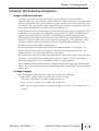
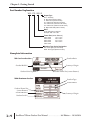
Part Number Explanation
WG - 175 - 060 - R
Output Type
ACC: Accessory
D: Dual shaft (cast-iron frame)
H: Hollow bore (cast-iron frame)
H1: Hollow bore (56C-face AL frame)
H2: Hollow bore (145TC-face AL frame)
H3: Hollow bore (182/4TC-face AL frame)
R: Right hand shaft (cast-iron frame)
Ratio
Three digit input for output of 1
Example: 060 = 60:1 ratio
Frame Size (center distance)
30M:
40M:
50M:
63M:
75M:
30mm
40mm
50mm
63mm
75mm
175:
206:
237:
262:
1.75 in
2.06 in
2.37 in
2.62 in
Gearbox Type Series Designation
WG: Worm gear (cast-iron frame)
WGA: Worm gear (aluminum frame)
Nameplate Information
Gearbox Ratio
WG Cast-Iron Gearbox
175
Gearbox Model #
WG-175-060-R
60
Country of Origin
70606827
Gearbox Serial #
WGA Aluminum Gearbox
Gearbox Frame Size (center distance)
Gearbox Type
Gearbox Ratio
Gearbox Frame Size
(center distance)
Gearbox Model #
Gearbox Serial #
1–4
Country of Origin
IronHorse® Worm Gearbox User Manual . . . . . . . . . . . . . .3rd Edition – 10/24/2014
CAST-IRON
WORM GEARBOXES
In This Chapter...
CHAPTER
2
Gearbox Selection Factors . . . . . . . . . . . . . . . . . . . . . . . . . . . . . . . . . .2–2
IronHorse® Cast-Iron Worm Gearbox Specifications . . . . . . . . . . . . .2–3
IronHorse® Cast-Iron Worm Gearbox Dimensions . . . . . . . . . . . . . . .2–7
IronHorse® Cast-Iron Worm Gearbox Accessory Mounting Bases . . .2–9
Chapter 2: Cast-Iron Worm Gearboxes
Gearbox Selection Factors
Service Factors and K Factors
Service Factors for Selecting Gearboxes
(when used with electric motors)
Service Continuity
(per day)
Occasional 1/2 hour
Less than 3 hours
3-10 hours
More than 10 hours
Load Characteristics
Uniform
Moderate
Shock*
Heavy
Shock*
Extreme
Shock*
1.00
1.00
1.00
1.25
1.00
1.00
1.25
1.50
1.00
1.25
1.50
1.75
1.25
1.50
1.75
2.00
* Shock results from sudden increases in the torque demand of the load, such as:
sudden stopping, restarting, and/or reversing; significantly heavy loads dropped
onto a moving conveyor; impact loads such as punch press operations.
Depending upon the load characteristics, divide the gearbox HP, Overhung Load,
and Maximum Mechanical Capacity ratings by the applicable service factor.
2–2
Overhung Load K Factors
for Various Drive Types
Chain & Sprocket
Gear
V-belt
Flat Belt
Variable Pitch Belt
1.00
1.25
1.50
2.50
3.50
Divide gearbox OHL ratings by
the applicable OHL K factors.
IronHorse® Worm Gearbox User Manual . . . . . . . . . . . . . .3rd Edition – 10/24/2014
Chapter 2: Cast-Iron Worm Gearboxes
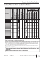
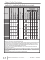
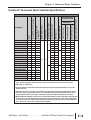
IronHorse® Cast-Iron Worm Gearbox Specifications
IronHorse Cast-Iron Worm Gearbox Specifications – Frame Size 175
Output RPM @ 1750 rpm Input
Nominal Motor HP 1
@ 1800 rpm
NEMA Motor Frame
350
1-1/2
56C
56C
20:1
88
3/4
56C
40:1
44
1/3
56C
60:1
29
1/4
56C
1.75 650 550
83
62
52
2.83 2.62
499
2.28 2.11
402
1.57 1.38
515
1.36 1.19
445
1.24 1.06
554
1.13 0.96
506
Input Power (hp)
Approx Weight (lb)
Efficiency (%)
Thrust Load 5 (lb)
Overhung Load 4 (lb)
Center Distance 3 (in)
85
Output Torque (lb·in)
3/4
Output Power (hp)
15:1 117
88
23
27
22
23
27
22
23
27
22
23
27
22
23
27
22
23
27
22
Input Power (hp)
56C
93
Output Torque (lb·in)
1
D
H
R
D
H
R
D
H
R
D
H
R
D
H
R
D
H
R
Thermal 7
Output Power (hp)
10:1 175
Output Type 2
Mechanical 6
Maximum Input Speed (rpm)
Ratio
5:1
Part Number
WG-175-005-D
WG-175-005-H
WG-175-005-R
WG-175-010-D
WG-175-010-H
WG-175-010-R
WG-175-015-D
WG-175-015-H
WG-175-015-R
WG-175-020-D
WG-175-020-H
WG-175-020-R
WG-175-040-D
WG-175-040-H
WG-175-040-R
WG-175-060-D
WG-175-060-H
WG-175-060-R
Maximum Ratings
@ 1750 rpm Input
2500
1.26 1.04
737
0.98 0.81
572
0.79 0.49
714
0.45 0.28
404
0.38 0.20
433
0.35 0.19
404
1) Nominal Motor HP is the highest HP 1800 rpm motor to be used with the gearbox under conditions of 1.0 service factor. Gearbox
input power capacity decreases as motor speed decreases and as service factor increases.
2) Output Type: D = Dual Shaft; H = Hollow Bore; R = Right-Hand Shaft
3) The Center Distance is the distance between the centerlines of the input and output shafts/bores; serves as the gearbox frame size.
4) Overhung Load ratings are for forces perpendicular to the output shaft and located at the shaft midpoint, such as from a gear,
pulley, or sprocket with a belt or chain. Divide OHL ratings by the applicable OHL K factors shown separately in the Selection
Factors tables. OHL ratings should also be divided by applicable service factors.
5) Thrust Load ratings are for forces along the axis of the output shaft, usually encountered in vertical-drive applications from
agitators, mixers, fans, blowers, etc.
6) Maximum Mechanical Ratings are limits based on strength and durability of gearbox components; applicable when operating time
is short and stopped time is greater than or equal to operating time. These ratings are applicable for 1.0 service factor loads, and
may require modification depending upon characteristics of the applicable driven loads. Refer to the “Service Factors” table for
more information.
7) Maximum Thermal Ratings are limits for gearbox continuous use without overheating.
10/24/2014 – 3rd Edition . . . . . . . . . . . . . .IronHorse® Worm Gearbox User Manual
2–3
Chapter 2: Cast-Iron Worm Gearboxes
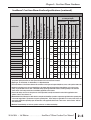
IronHorse® Cast-Iron Worm Gearbox Specifications (continued)
Ratio
Output RPM @ 1750 rpm Input
Nominal Motor HP 1
@ 1800 rpm
NEMA Motor Frame
5:1
350
2
56C
56C
20:1
88
1
56C
40:1
44
1/2
56C
60:1
29
1/3
56C
2.06 700 750
82
71
58
3.62 3.33
925
2.57 2.36
657
2.77 2.50
935
2.10 1.89
708
2.09 1.78 1002 1.40 1.20
673
27.9
32
27.3
27.9
32
27.3
27.9
32
27.3
27.9
32
27.3
27.9
32
27.3
27.9
32
27.3
Input Power (hp)
Approx Weight (lb)
Efficiency (%)
Thrust Load 5 (lb)
Overhung Load 4 (lb)
85
Output Torque (lb·in)
1
Output Power (hp)
15:1 117
90
Input Power (hp)
56C
Output Torque (lb·in)
1-1/2
92
Thermal 7
Output Power (hp)
10:1 175
D
H
R
D
H
R
D
H
R
D
H
R
D
H
R
D
H
R
Center Distance 3 (in)
Mechanical 6
Output Type 2
Part Number
WG-206-005-D
WG-206-005-H
WG-206-005-R
WG-206-010-D
WG-206-010-H
WG-206-010-R
WG-206-015-D
WG-206-015-H
WG-206-015-R
WG-206-020-D
WG-206-020-H
WG-206-020-R
WG-206-040-D
WG-206-040-H
WG-206-040-R
WG-206-060-D
WG-206-060-H
WG-206-060-R
Maximum Ratings
@ 1750 rpm Input
Maximum Input Speed (rpm)
IronHorse Cast-Iron Worm Gearbox Specifications – Frame Size 206
2500
1.57 1.29
914
1.17 0.96
681
1.09 0.77 1120 0.71 0.50
726
0.60 0.35
606
750
0.48 0.28
1) Nominal Motor HP is the highest HP 1800 rpm motor to be used with the gearbox under conditions of 1.0 service factor. Gearbox
input power capacity decreases as motor speed decreases and as service factor increases.
2) Output Type: D = Dual Shaft; H = Hollow Bore; R = Right-Hand Shaft
3) The Center Distance is the distance between the centerlines of the input and output shafts/bores; serves as the gearbox frame size.
4) Overhung Load ratings are for forces perpendicular to the output shaft and located at the shaft midpoint, such as from a gear,
pulley, or sprocket with a belt or chain. Divide OHL ratings by the applicable OHL K factors shown separately in the Selection
Factors tables. OHL ratings should also be divided by applicable service factors.
5) Thrust Load ratings are for forces along the axis of the output shaft, usually encountered in vertical-drive applications from
agitators, mixers, fans, blowers, etc.
6) Maximum Mechanical Ratings are limits based on strength and durability of gearbox components; applicable when operating time
is short and stopped time is greater than or equal to operating time. These ratings are applicable for 1.0 service factor loads, and
may require modification depending upon characteristics of the applicable driven loads. Refer to the “Service Factors” table for
more information.
7) Maximum Thermal Ratings are limits for gearbox continuous use without overheating.
2–4
IronHorse® Worm Gearbox User Manual . . . . . . . . . . . . . .3rd Edition – 10/24/2014
Chapter 2: Cast-Iron Worm Gearboxes
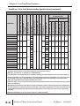
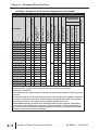
IronHorse® Cast-Iron Worm Gearbox Specifications (continued)
IronHorse Cast-Iron Worm Gearbox Specifications – Frame Size 237
Output RPM @ 1750 rpm Input
Nominal Motor HP 1
@ 1800 rpm
350
3
10:1 175
1-1/2
15:1 117
1
56C
20:1
88
1
40:1
44
1/2
60:1
29
1/2
89
84
2.37 900 900
82
71
61
Output Torque (lb·in)
Input Power (hp)
Output Power (hp)
Output Torque (lb·in)
4.32 4.02
766
3.56 3.31
630
37.6
38
36.7
37.6
38
36.7
37.6
38
36.7
37.6
38
36.7
37.6
38
36.7
37.6
38
36.7
Input Power (hp)
Approx Weight (lb)
Efficiency (%)
Thrust Load 5 (lb)
Overhung Load 4 (lb)
93
Thermal 7
Output Power (hp)
D
H
R
D
H
R
D
H
R
D
H
R
D
H
R
D
H
R
Center Distance 3 (in)
Output Type 2
NEMA Motor Frame
Mechanical 6
Maximum Input Speed (rpm)
Ratio
5:1
Part Number
WG-237-005-D
WG-237-005-H
WG-237-005-R
WG-237-010-D
WG-237-010-H
WG-237-010-R
WG-237-015-D
WG-237-015-H
WG-237-015-R
WG-237-020-D
WG-237-020-H
WG-237-020-R
WG-237-040-D
WG-237-040-H
WG-237-040-R
WG-237-060-D
WG-237-060-H
WG-237-060-R
Maximum Ratings
@ 1750 rpm Input
3.47 3.09 1158 2.24 1.99
746
2.64 2.22 1249 1.55 1.30
732
2500
2.06 1.69 1195 1.36 1.12
791
1.45 1.02 1483 0.83 0.58
845
0.86 0.53 1149 0.63 0.39
844
1) Nominal Motor HP is the highest HP 1800 rpm motor to be used with the gearbox under conditions of 1.0 service factor. Gearbox
input power capacity decreases as motor speed decreases and as service factor increases.
2) Output Type: D = Dual Shaft; H = Hollow Bore; R = Right-Hand Shaft
3) The Center Distance is the distance between the centerlines of the input and output shafts/bores; serves as the gearbox frame size.
4) Overhung Load ratings are for forces perpendicular to the output shaft and located at the shaft midpoint, such as from a gear,
pulley, or sprocket with a belt or chain. Divide OHL ratings by the applicable OHL K factors shown separately in the Selection
Factors tables. OHL ratings should also be divided by applicable service factors.
5) Thrust Load ratings are for forces along the axis of the output shaft, usually encountered in vertical-drive applications from
agitators, mixers, fans, blowers, etc.
6) Maximum Mechanical Ratings are limits based on strength and durability of gearbox components; applicable when operating time
is short and stopped time is greater than or equal to operating time. These ratings are applicable for 1.0 service factor loads, and
may require modification depending upon characteristics of the applicable driven loads. Refer to the “Service Factors” table for
more information.
7) Maximum Thermal Ratings are limits for gearbox continuous use without overheating.
10/24/2014 – 3rd Edition . . . . . . . . . . . . . .IronHorse® Worm Gearbox User Manual
2–5
Chapter 2: Cast-Iron Worm Gearboxes
IronHorse® Cast-Iron Worm Gearbox Specifications (continued)
IronHorse Cast-Iron Worm Gearbox Specifications – Frame Size 262
Output RPM @ 1750 rpm Input
Nominal Motor HP 1
@ 1800 rpm
350
3
182TC
10:1 175
2
15:1 117
2
20:1
88
1-1/2
56C
40:1
44
3/4
60:1
29
3/4
90
87
2.62 1000 1000
83
72
66
Output Torque (lb·in)
Input Power (hp)
Output Power (hp)
Output Torque (lb·in)
57.0
50
55.7
57.0
50
55.7
49.9
50
48.6
49.9
50
48.6
49.9
50
48.6
49.9
50
48.6
5.24 4.86
924
4.32 4.00
761
Input Power (hp)
Approx Weight (lb)
Efficiency (%)
Thrust Load 5 (lb)
Overhung Load 4 (lb)
93
Thermal 7
Output Power (hp)
D
H
R
D
H
R
D
H
R
D
H
R
D
H
R
D
H
R
Center Distance 3 (in)
Output Type 2
NEMA Motor Frame
Mechanical 6
Maximum Input Speed (rpm)
Ratio
5:1
Part Number
WG-262-005-D
WG-262-005-H
WG-262-005-R
WG-262-010-D
WG-262-010-H
WG-262-010-R
WG-262-015-D
WG-262-015-H
WG-262-015-R
WG-262-020-D
WG-262-020-H
WG-262-020-R
WG-262-040-D
WG-262-040-H
WG-262-040-R
WG-262-060-D
WG-262-060-H
WG-262-060-R
Maximum Ratings
@ 1750 rpm Input
4.17 3.74 1445 3.06 2.75 1061
3.22 2.81 1577 2.47 2.16 1212
2500
2.67 2.21 1563 1.84 1.53 1078
1.85 1.32 1919 1.11 0.80 1153
1.16 0.77 1670 0.94 0.62 1346
1) Nominal Motor HP is the highest HP 1800 rpm motor to be used with the gearbox under conditions of 1.0 service factor. Gearbox
input power capacity decreases as motor speed decreases and as service factor increases.
2) Output Type: D = Dual Shaft; H = Hollow Bore; R = Right-Hand Shaft
3) The Center Distance is the distance between the centerlines of the input and output shafts/bores; serves as the gearbox frame size.
4) Overhung Load ratings are for forces perpendicular to the output shaft and located at the shaft midpoint, such as from a gear, pulley,
or sprocket with a belt or chain. Divide OHL ratings by the applicable OHL K factors shown separately in the Selection Factors
tables. OHL ratings should also be divided by applicable service factors.
5) Thrust Load ratings are for forces along the axis of the output shaft, usually encountered in vertical-drive applications from agitators,
mixers, fans, blowers, etc.
6) Maximum Mechanical Ratings are limits based on strength and durability of gearbox components; applicable when operating time is
short and stopped time is greater than or equal to operating time. These ratings are applicable for 1.0 service factor loads, and may
require modification depending upon characteristics of the applicable driven loads. Refer to the “Service Factors” table for more
information.
7) Maximum Thermal Ratings are limits for gearbox continuous use without overheating.
2–6
IronHorse® Worm Gearbox User Manual . . . . . . . . . . . . . .3rd Edition – 10/24/2014
Chapter 2: Cast-Iron Worm Gearboxes
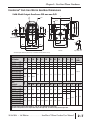
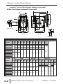
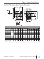
IronHorse® Cast-Iron Worm Gearbox Dimensions
Solid-Shaft Output Gearboxes WG-xxx-xxx-D/R
A
ØLA
4-Z1
AB
H
N
N*
LL
Y2
ØLA
ØS*
ØLB
L1*
CC
L1
X2
ØLC
ØS
2x4-Z
LE
Output Shaft View
BE
BD
BB
X
F/2
Y
F
BB*
AC
B
W
B*
Input Shaft View
Left View
Rear View
* Left side output shafts are present only on dual-shaft models (WG-xxx-xxx-D)
WG-175-xxx-D/R
WG-206-xxx-D/R
WG-237-xxx-D/R
WG-262-005-D/R
WG-262-010-D/R
WG-262-015-D/R
WG-262-020-D/R
WG-262-040-D/R
WG-262-060-D/R
Part #
(repeated)
WG-175-xxx-D/R
WG-206-xxx-D/R
WG-237-xxx-D/R
WG-262-005-D/R
WG-262-010-D/R
WG-262-015-D/R
WG-262-020-D/R
WG-262-040-D/R
WG-262-060-D/R
A
AB
AC
B
BB
BD
BE
CC
F
H
LL
56C
7.29
7.95
8.71
4.035
4.37
4.705
5.06
5.75
6.38
6.83
7.25
7.95
4.311
4.69
5.087
3.56
3.82
4.06
2.75
2.88
2.88
1.75
2.062
2.375
4.188
5
5
5.75
6.38
6.94
2.062
2.281
2.5
182TC 10.57
6.24
7.17
8.87
5.63
4.69
3.375
2.625
6.375
8
2.938
Z
(UNC)
5/16-18
3/8-16
56C
9.41
5.059
Frame
Part Number
Frame
Dimensions (inches) – IronHorse Cast-Iron Worm Gearboxes – Solid-Shaft Outputs
LA
LB
LC
LE
Z1
W
X
Y
L1
N
56C
5.875
4.5
6.496
0.157
0.433
0.625
3/16
3/32
1
1.25
1.25
1.781
2.09
2.37
182TC
7.25
8.5
9
0.197
0.551
1.125
1/4
1/8
2
2.626
56C
Flange
5.875
4.5
6.496
Input Shaft
0.157
0.433
0.625
3/16
Output Shaft
S
X2
Y2
0.875 3/16 3/32
1
1.125
1/4
1/8
3/32
Dual-shaft output gearboxes have B, BB, L1, S, N, X2, & Y2 dimensions on both sides.
Right-hand shaft gearboxes have output shafts only on the right side, as viewed looking into the input shaft.
10/24/2014 – 3rd Edition . . . . . . . . . . . . . .IronHorse® Worm Gearbox User Manual
2–7
Chapter 2: Cast-Iron Worm Gearboxes
IronHorse® Cast-Iron Worm Gearbox Dimensions (continued)
Hollow-Bore Output Gearboxes WG-xxx-xxx-H
A
A
ØL
4-Z1
AB
2x4-Z
ØLB
2x3-Z2
ØLC
CC
U
H
ØS
LL
V
LE
T
Output Shaft View
F/2
BE
N
BB
X
F
BD
AC
BB
Rear View
Y
Left View
W
Input Shaft View
Part Number
Part Number
(repeated)
WG-175-xxx-H
WG-206-xxx-H
WG-237-xxx-H
WG-262-005-H
WG-262-010-H
WG-262-015-H
WG-262-020-H
WG-262-040-H
WG-262-060-H
2–8
A
AB
AC
BB
BD
BE
CC
F
H
56C
7.28
7.95
8.68
4.035
4.370
4.705
5.059
5.748
6.378
3.091
3.219
3.220
3.563
3.819
4.055
2.750
2.880
2.880
1.75
2.062
2.375
4.188
5.000
5.000
5.75
6.375
6.937
2.062 5/16-18
2.281
2.500
7.165
3.500
4.685
3.375
2.625
6.375
8.000
2.938
LL
182
10.59 6.240
TC
56C
Frame
WG-175-xxx-H
WG-206-xxx-H
WG-237-xxx-H
WG-262-005-H
WG-262-010-H
WG-262-015-H
WG-262-020-H
WG-262-040-H
WG-262-060-H
Frame
Dimensions (inches) – IronHorse Cast-Iron Worm Gearboxes – Hollow-Bore Outputs
9.41
3/8-16
5.059
Flange
LA
Z
(UNC)
Input Shaft
Output Bore
LC
LE
Z1
W
X
Y
N
S
T
U
56C 5.875
4.5
6.496
0.157
0.433
0.625
3/16
3/32
0.787
0.797
0.661
1.575
1.772
1.969
1.0
1.125
1.250
1/4
7/64 #10-32
1/8
7/64
182
TC
8.5
9.000
0.197
0.551
1.125
1/4
1/8
0.626
2.362
1.437
3/8
5/32
7.25
56C 5.875
V
Z2
(UNF)
LB
1/4-28
4.5
6.496
0.157
0.433
0.625
3/16
3/32
IronHorse® Worm Gearbox User Manual . . . . . . . . . . . . . .3rd Edition – 10/24/2014
Chapter 2: Cast-Iron Worm Gearboxes
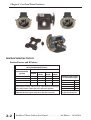
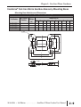
IronHorse® Cast-Iron Worm Gearbox Accessory Mounting Bases
Mounting Base Selection and Dimensions
IronHorse Worm Gearbox Mounting Bases
Part Number
WG-175-BASE
WG-206-BASE
WG-237-BASE
WG-262-BASE
Fits Gearbox
Numbers
Approx
Weight
(lb)
A
B
C
D
E
F
t
d1
d2
d3
WG-175-xxx-x
WG-206-xxx-x
WG-237-xxx-x
WG-262-xxx-x
4.0
4.8
6.2
7.5
4.19
5.00
5.00
6.38
2.76
2.88
2.88
3.38
4.50
4.69
4.88
5.25
5.75
6.38
7.06
8.00
5.69
5.91
6.22
6.69
7.00
7.76
8.50
9.65
0.69
0.72
0.75
0.75
0.43
0.47
0.47
0.55
0.35
0.43
0.43
0.43
0.55
0.69
0.69
0.69
Dimensions (in)
4 - Ød1
B
C
E
A
D
F
4 – Ød2
t
4 – Ød3
10/24/2014 – 3rd Edition . . . . . . . . . . . . . .IronHorse® Worm Gearbox User Manual
2–9
Chapter 2: Cast-Iron Worm Gearboxes
BLANK
PAGE
2–10
IronHorse® Worm Gearbox User Manual . . . . . . . . . . . . . .3rd Edition – 10/24/2014
ALUMINUM
WORM GEARBOXES
In This Chapter...
CHAPTER
3
Gearbox Selection Factors . . . . . . . . . . . . . . . . . . . . . . . . . . . . . . . . . .3–2
Service Factors and K Factors . . . . . . . . . . . . . . . . . . . . . . . . . . . . . . . . . . . . . . . . . .3–2
IronHorse® Aluminum Worm Gearbox Specifications . . . . . . . . . . . . .3–3
IronHorse® Aluminum Worm Gearbox Dimensions . . . . . . . . . . . . . .3–5
IronHorse® Aluminum Worm Gearbox Accessories . . . . . . . . . . . . . . .3–6
Chapter 3: Aluminum Worm Gearboxes
Gearbox Selection Factors
Service Factors and K Factors
Service Factors for Selecting Gearboxes
(when used with electric motors)
Service Continuity
(per day)
Occasional 1/2 hour
Less than 3 hours
3-10 hours
More than 10 hours
Load Characteristics
Uniform
Moderate
Shock*
Heavy
Shock*
Extreme
Shock*
1.00
1.00
1.00
1.25
1.00
1.00
1.25
1.50
1.00
1.25
1.50
1.75
1.25
1.50
1.75
2.00
* Shock results from sudden increases in the torque demand of the load, such as:
sudden stopping, restarting, and/or reversing; significantly heavy loads dropped
onto a moving conveyor; impact loads such as punch press operations.
Depending upon the load characteristics, divide the gearbox HP, Overhung Load,
and Maximum Mechanical Capacity ratings by the applicable service factor.
3–2
Overhung Load K Factors
for Various Drive Types
Chain & Sprocket
Gear
V-belt
Flat Belt
Variable Pitch Belt
1.00
1.25
1.50
2.50
3.50
Divide gearbox OHL ratings by
the applicable OHL K factors.
IronHorse® Worm Gearbox User Manual . . . . . . . . . . . . . .3rd Edition – 10/24/2014
Chapter 3: Aluminum Worm Gearboxes
IronHorse® Aluminum Worm Gearbox Specifications
IronHorse Aluminum Worm Gearbox Specifications – Frame Sizes 30, 40, 50 mm
Output RPM @ 1750 rpm Input
Nominal Motor HP 1
@ 1800 rpm
175
88
58
44
29
175
88
58
44
29
22
17.5
175
88
58
44
29
22
17.5
0.5
0.25
0.25
0.2
0.12
1
0.5
0.5
0.33
0.25
0.12
0.12
2
1
0.75
0.75
0.33
0.33
0.25
Maximum Input Speed (rpm)
Ratio
10:1
20:1
30:1
40:1
60:1
10:1
20:1
30:1
40:1
60:1
80:1
100:1
10:1
20:1
30:1
40:1
60:1
80:1
100:1
Approx Weight (lb)
3
5
8
Output Torque (lb·in)
50
80
72
62
55
46
83
78
68
65
56
50
47
84
78
70
65
57
50
46
Output Power (hp)
H
142
179
205
225
259
279
350
403
441
507
556
595
406
510
586
643
739
810
866
Input Power (hp)
40
56C
Efficiency (%)
30
Overhung Load 4 (lb)
Center Distance 3 (mm)
Output Type 2
Mechanical 5
NEMA Motor Frame
Part Number
WGA-30M-010-H1
WGA-30M-020-H1
WGA-30M-030-H1
WGA-30M-040-H1
WGA-30M-060-H1
WGA-40M-010-H1
WGA-40M-020-H1
WGA-40M-030-H1
WGA-40M-040-H1
WGA-40M-060-H1
WGA-40M-080-H1
WGA-40M-100-H1
WGA-50M-010-H1
WGA-50M-020-H1
WGA-50M-030-H1
WGA-50M-040-H1
WGA-50M-060-H1
WGA-50M-080-H1
WGA-50M-100-H1
Maximum Ratings
@ 1750 rpm Input
0.54
0.30
0.25
0.19
0.12
1.15
0.61
0.53
0.39
0.25
0.19
0.15
2.06
1.13
0.95
0.70
0.46
0.38
0.28
0.43
0.22
0.16
0.10
0.06
0.95
0.48
0.36
0.25
0.14
0.10
0.07
1.73
0.88
0.67
0.46
0.26
0.19
0.13
150
150
177
150
142
354
345
389
363
319
283
257
628
646
734
664
602
566
487
2,000
1) Nominal Motor HP is the highest HP 1800 rpm motor to be used with the gearbox under conditions of 1.0 service
factor. Gearbox input power capacity decreases as motor speed decreases and as service factor increases.
2) Output Type: H = Hollow Bore.
3) The Center Distance is the distance between the centerlines of the input and output shafts/bores; serves as the
gearbox frame size.
4) Overhung Load ratings are for forces perpendicular to the output shaft and located at the shaft midpoint, such as
from a gear, pulley, or sprocket with a belt or chain. Divide OHL ratings by the applicable OHL K factors shown
separately in the Selection Factors tables. OHL ratings should also be divided by applicable service factors.
5) Maximum Mechanical Ratings are limits based on strength and durability of gearbox components; applicable when
operating time is short and stopped time is greater than or equal to operating time. These ratings are applicable
for 1.0 service factor loads, and may require modification depending upon characteristics of the applicable driven
loads. Refer to the “Service Factors” table for more information.
3rd Edition – 10/24/2014 . . . . . . . . . . . . . . .IronHorse® Worm Gearbox User Manual
3–3
Chapter 3: Aluminum Worm Gearboxes
IronHorse® Aluminum Worm Gearbox Specifications (continued)
Ratio
Output RPM @ 1750 rpm Input
Nominal Motor HP 1
@ 1800 rpm
NEMA Motor Frame
10:1
10:1
20:1
20:1
30:1
40:1
60:1
80:1
100:1
10:1
10:1
10:1
20:1
20:1
30:1
40:1
60:1
80:1
100:1
175
175
88
88
58
44
29
22
18
175
175
175
88
88
58
44
29
22
18
3
3
2
2
1.5
1
0.75
0.5
0.5
5
5
5
3
3
2
1.5
1
0.75
0.75
56C
145TC
56C
145TC
56C
56C
56C
56C
56C
56C
145TC
182/4TC
56C
145TC
56C
56C
56C
56C
56C
13
19
Output Torque (lb·in)
Approx Weight (lb)
86
86
80
80
73
70
59
53
48
86
86
86
79
79
72
68
62
58
52
Output Power (hp)
75
510
510
641
641
736
807
928
1017
1088
604
604
604
759
759
873
957
1099
1205
1289
Input Power (hp)
H
Efficiency (%)
63
Overhung Load 4 (lb)
Center Distance 3 (mm)
Mechanical 5
Output Type 2
Part Number
WGA-63M-010-H1
WGA-63M-010-H2
WGA-63M-020-H1
WGA-63M-020-H2
WGA-63M-030-H1
WGA-63M-040-H1
WGA-63M-060-H1
WGA-63M-080-H1
WGA-63M-100-H1
WGA-75M-010-H1
WGA-75M-010-H2
WGA-75M-010-H3
WGA-75M-020-H1
WGA-75M-020-H2
WGA-75M-030-H1
WGA-75M-040-H1
WGA-75M-060-H1
WGA-75M-080-H1
WGA-75M-100-H1
Maximum Ratings
@ 1750 rpm Input
3.67
3.67
2.04
2.04
1.76
1.26
0.86
0.67
0.57
5.44
5.44
5.44
3.14
3.14
2.48
1.88
1.26
0.97
0.80
3.16
3.16
1.63
1.63
1.28
0.88
0.51
0.36
0.27
4.68
4.68
4.68
2.48
2.48
1.79
1.28
0.78
0.56
0.42
1141
1141
1186
1186
1416
1274
1141
1071
1035
1717
1717
1717
1849
1849
2026
1947
1770
1672
1593
Maximum Input Speed (rpm)
IronHorse Aluminum Worm Gearbox Specifications – Frame Sizes 63 & 75 mm
2,000
1) Nominal Motor HP is the highest HP 1800 rpm motor to be used with the gearbox under conditions of 1.0 service factor.
Gearbox input power capacity decreases as motor speed decreases and as service factor increases.
2) Output Type: H = Hollow Bore.
3) The Center Distance is the distance between the centerlines of the input and output shafts/bores; serves as the gearbox
frame size.
4) Overhung Load ratings are for forces perpendicular to the output shaft and located at the shaft midpoint, such as from a
gear, pulley, or sprocket with a belt or chain. Divide OHL ratings by the applicable OHL K factors shown separately in
the Selection Factors tables. OHL ratings should also be divided by applicable service factors.
5) Maximum Mechanical Ratings are limits based on strength and durability of gearbox components; applicable when
operating time is short and stopped time is greater than or equal to operating time. These ratings are applicable for
1.0 service factor loads, and may require modification depending upon characteristics of the applicable driven loads.
Refer to the “Service Factors” table for more information.
3–4
IronHorse® Worm Gearbox User Manual . . . . . . . . . . . . . .3rd Edition – 10/24/2014
Chapter 3: Aluminum Worm Gearboxes
IronHorse® Aluminum Worm Gearbox Dimensions
Dimensions (inches) – IronHorse Aluminum Worm Gearboxes
Part Number
NEMA
Motor
Face
WGA-30M-xxx-H1
WGA-40M-xxx-H1
WGA-50M-xxx-H1
Output Bore
A
B
C
D
E
F
G
Input Shaft
H
ØQ
K
L
ØM
N
O
ØP
3.82 2.48 3.15 2.24 1.57 1.18 2.89 1.57 0.720 0.20 0.625 0.73 0.19 0.625 6.50
56C
WGA-63M-xxx-H1
4.78 3.07 3.94 2.81 1.97 1.57 3.18 1.97 0.840 0.20 0.750 0.71 0.19 0.625 6.50
5.67 3.62 4.72 3.31 2.36 1.97 3.58 2.36 1.110 0.24 1.000 0.71 0.19 0.625 6.50
6.87 4.42 5.69 4.00 2.87 2.48 4.06 2.84 1.250 0.31 1.125 0.71 0.19 0.625 6.50
WGA-63M-xxx-H2
145TC
6.87 4.42 5.69 4.00 2.87 2.48 4.06 2.84 1.250 0.31 1.125 0.97 0.19 0.875 6.50
WGA-75M-xxx-H1
56C
8.07 4.72 6.77 4.69 3.39 2.95 4.68 3.39 1.375 0.31 1.250 0.71 0.19 0.625 6.50
WGA-75M-xxx-H2
145TC
8.07 4.72 6.77 4.69 3.39 2.95 4.68 3.39 1.375 0.31 1.250 1.24 0.25 1.125 6.50
WGA-75M-xxx-H3 182/4TC 8.07 4.72 6.77 4.69 3.39 2.95 4.68 3.39 1.375 0.31 1.250 1.24 0.25 1.125 8.97
See our website: www.AutomationDirect.com for complete Engineering drawings.
3rd Edition – 10/24/2014 . . . . . . . . . . . . . . .IronHorse® Worm Gearbox User Manual
3–5
Chapter 3: Aluminum Worm Gearboxes
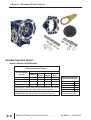
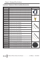
IronHorse® Aluminum Worm Gearbox Accessories
IronHorse Aluminum Worm Gearbox Accessories
Part Number
Description
Typical Photo
WGA-30M-ACC1 Output flange, for aluminum WGA-30M series gearboxes. Includes (4) mounting screws.
WGA-40M-ACC1 Output flange, for aluminum WGA-40M series gearboxes. Includes (4) mounting screws.
WGA-50M-ACC1 Output flange, for aluminum WGA-50M series gearboxes. Includes (4) mounting screws.
WGA-63M-ACC1 Output flange, for aluminum WGA-63M series gearboxes. Includes (8) mounting screws.
WGA-75M-ACC1 Output flange, for aluminum WGA-75M series gearboxes. Includes (8) mounting screws.
WGA-30M-ACC2 Torque arm, for aluminum WGA-30M series gearboxes. Includes (4) mounting screws.
WGA-40M-ACC2 Torque arm, for aluminum WGA-40M series gearboxes. Includes (4) mounting screws.
WGA-50M-ACC2 Torque arm, for aluminum WGA-50M series gearboxes. Includes (4) mounting screws.
WGA-63M-ACC2 Torque arm, for aluminum WGA-63M series gearboxes. Includes (8) mounting screws.
WGA-75M-ACC2 Torque arm, for aluminum WGA-75M series gearboxes. Includes (8) mounting screws.
WGA-30M-ACC3
Single output shaft, Ø0.625 in, for aluminum WGA-30M series gearboxes.
Includes (3) keys, (1) spacer, and (1) retaining ring.
Single output shaft, Ø0.75 in, for aluminum WGA-40M series gearboxes.
Includes (3) keys, (1) spacer, and (1) retaining ring.
Single output shaft, Ø1.0 in, for aluminum WGA-50M series gearboxes.
WGA-50M-ACC3
Includes (3) keys, (1) spacer, and (1) retaining ring.
WGA-40M-ACC3
Single output shaft, Ø1.125 in, for aluminum WGA-63M series gearboxes.
Includes (3) keys, (1) spacer, and (1) retaining ring.
Single output shaft, Ø1.25 in, for aluminum WGA-75M series gearboxes.
WGA-75M-ACC3
Includes (3) keys, (1) spacer, and (1) retaining ring.
WGA-63M-ACC3
WGA-30M-ACC4
WGA-40M-ACC4
WGA-50M-ACC4
WGA-63M-ACC4
WGA-75M-ACC4
Double output shaft, Ø0.625 in, for aluminum WGA-30M series gearboxes.
Includes (4) keys, (2) spacers, and (2) retaining rings.
Double output shaft, Ø0.75 in, for aluminum WGA-40M series gearboxes.
Includes (4) keys, (2) spacers, and (2) retaining rings.
Double output shaft, Ø1.0 in, for aluminum WGA-50M series gearboxes.
Includes (4) keys, (2) spacers, and (2) retaining rings.
Double output shaft, Ø1.125 in, for aluminum WGA-63M series gearboxes.
Includes (4) keys, (2) spacers, and (2) retaining rings.
Double output shaft, Ø1.25 in, for aluminum WGA-75M series gearboxes.
Includes (4) keys, (2) spacers, and (2) retaining rings.
WGA-30M-ACC5 Output cover, for aluminum WGA-30M series gearboxes. Includes (4) mounting screws.
WGA-40M-ACC5 Output cover, for aluminum WGA-40M series gearboxes. Includes (4) mounting screws.
WGA-50M-ACC5 Output cover, for aluminum WGA-50M series gearboxes. Includes (4) mounting screws.
WGA-63M-ACC5 Output cover, for aluminum WGA-63M series gearboxes. Includes (4) mounting screws.
WGA-75M-ACC5 Output cover, for aluminum WGA-75M series gearboxes. Includes (4) mounting screws.
3–6
IronHorse® Worm Gearbox User Manual . . . . . . . . . . . . . .3rd Edition – 10/24/2014
INSTALLATION
AND LUBRICATION
In This Chapter...
CHAPTER
4
IronHorse® Worm Gearbox Installation . . . . . . . . . . . . . . . . . . . . . . . .4–2
Installation Instructions . . . . . . . . . . . . . . . . . . . . . . . . . . . . . . . . . . . . . . . . . . . . . .4–2
Vent Plug Installation (Cast-Iron Gearboxes only) . . . . . . . . . . . . . . . . . . . . . . . . .4–3
IronHorse® Worm Gearbox Lubrication & Mounting Orientations . .4–4
Lubrication Instructions . . . . . . . . . . . . . . . . . . . . . . . . . . . . . . . . . . . . . . . . . . . . . .4–4
Lubricant Capacities & Mounting Orientations . . . . . . . . . . . . . . . . . . . . . . . . . . . .4–5
Chapter 4: Installation and Lubrication
IronHorse® Worm Gearbox Installation
Read these instructions thoroughly before installing or operating the gearbox.
Installation Instructions
• Leave the protective shaft sleeves in place for safe handling of the gearbox during installation.
• Add or partially drain oil as needed depending upon the mounting orientation.
(Refer to the lubrication section of this chapter for more information.)
• Install the vent plug.
(Not required for aluminum gearboxes; refer to the next subsection for more information.)
• Align all shafts accurately, since improper alignment can result in premature failure.
Use flexible couplings to compensate for slight misalignment.
• For hollow-bore output gearboxes – Use anti-seize compound when inserting the load shaft into the
hollow output shaft. It is preferrable to size the load shaft with sufficient length to allow complete
insertion through the hollow output shaft of the gearbox. This allows equal support of the load
shaft by both of the output shaft bearings, and permits the use of the output shaft setscrews to lock
the two shafts together on both sides of the gearbox. At minimum, the load shaft should be
inserted at least half way into the hollow output shaft, and secured with the setscrews on the
insertion end of the gearbox.
• Mount the gearbox to a rigid foundation, and use the maximum possible bolt size. Periodically
inspect the mounting bolts. (Do NOT mount gearbox vertically with input shaft pointing
downward. Refer to the lubrication section of this chapter for allowable mounting orientations.)
• Optional gearbox and motor mounting bases are available for ease of mounting and alignment.
• Mount auxiliary drive components such as sprockets, gears and pulleys on the gearbox shaft as close
to the housing as possible in order to minimize the effects of overhung loads. Avoid force fits that
might damage bearings or gears.
• Check and record gear backlash at installation and again at regular intervals. This should be done
by measuring the rotary movement of the output shaft, rotating the shaft alternately clockwise and
counterclockwise at a suitable radius while holding the input shaft stationary. The gearbox should
be replaced when the backlash exceeds four times the measurement taken at installation.
• Gear drives are rated for 1750 input rpm and Class I Service (Service Factor 1.0), using Mobil
SHC634 synthetic lubricant.
• Initial operating temperatures may be higher than normal during the break-in period of the gear set.
For maximum life, DO NOT ALLOW THE GEARBOX TO OPERATE CONTINUOUSLY
ABOVE 225°F at the gear case. In the event of overheating, check for overloads or high ambient
temperatures. Keep shafts and vent plugs clean to prevent foreign particles from entering seals or
gear housing.
4–2
IronHorse® Worm Gearbox User Manual . . . . . . . . . . . . . .3rd Edition – 10/24/2014
Chapter 4: Installation and Lubrication
Vent Plug Installation – (Cast-Iron Gearboxes only)
All IronHorse Worm Gearboxes are tested and filled with Mobil SHC634 synthetic lubricant prior
to shipment. All vent openings are plugged by the manufacturer to prevent the loss of lubricant in
shipment. The vent plug is shipped loose in the package with cast-iron gearboxes, and should be
installed prior to placing the gearbox in operation.
• The ventplug should be installed in the uppermost position.
(Use of a vent plug not necessary for aluminum gearboxes; vent plug not provided.)
• For all mounting positions where the vented plug is located in a horizontal plane, the vent hole
must point upward.
• For all mounting positions where the vented plug is located in a vertical plane, the vent hole must
point toward the center of the gearbox housing.
• Failure to properly install the vent plug can lead to pressurization of the gearbox housing as
operating temperature rises, resulting in leakage at the shaft seals.
3rd Edition – 10/24/2014 . . . . . . . . . . . . . .IronHorse® Worm Gearbox User Manual
4–3
Chapter 4: Installation and Lubrication
IronHorse® Worm Gearbox Lubrication & Mounting Orientations
Lubricant selection is important to all gearboxes, and it is particularly critical for the worm gear
type. An oil with special characteristics and a relatively high viscosity is required due to sliding
action between the gear teeth where they mesh. Aside from improper gearbox selection,
inadequate lubrication is the greatest factor contributing to premature worm gearbox failures.
Improper lubrication also causes reduced gearbox performance.
Lubrication Instructions
IronHorse Worm Gearboxes are shipped to you filled with Mobil SHC634 synthetic oil.
Oil must be added or partially drained depending upon your mounting orientation, as
shown in the Lubricant Capacities table.
Since many oils are not suitable for worm gears, it is very important to use the proper lubricant
type. It is also very important to keep the oil free from oxidation and contamination by water or
debris. For longer service life, the gearbox should be periodically drained (preferably while warm)
and refilled to the proper level with a recommended gear oil. Non-synthetic oils should be
changed every 6 months or 250 hours of operation under normal operating conditions. However,
synthetic lubricants have increased resistance to thermal and oxidation degradation, and do not
need to be changed as frequently.
Synthetic lubricant should be changed every 6,000 hours of operation or every two
years, which ever comes first.
WARNING: Some lubricants contain non-corrosive extreme pressure additives. DO NOT USE
lubricants that contain sulphur and/or chlorine, which are corrosive to bronze gears. Also, some
extreme pressure lubricants contain materials that are toxic. Avoid the use of these lubricants where
harmful effects can occur.
4–4
IronHorse® Worm Gearbox User Manual . . . . . . . . . . . . . .3rd Edition – 10/24/2014
Chapter 4: Installation and Lubrication
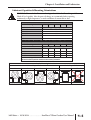
Lubricant Capacities & Mounting Orientations
WARNING: Too much oil will cause overheating, and too little oil will result in gear failure.
Check oil level regularly. More frequent oil changes are recommended when operating
continuously, at high temperatures, or under conditions of extreme dirt or dust.
IronHorse Aluminum Worm Gearbox Lubricant Capacities
Gearbox Mounting Orientation
A
Gearbox Part Number
WGA-30M-xxx-xx
WGA-40M-xxx-xx
WGA-50M-xxx-xx
WGA-63M-xxx-xx
WGA-75M-xxx-xx
B
C
D
E
Approx Capacity (fl oz)
1.69
3.38
5.07
10.14
16.91
IronHorse Cast-Iron Worm Gearbox Lubricant Capacities
Gearbox Mounting Orientation
Gearbox Part Number
WG-175-xxx-x
WG-206-xxx-x
WG-237-xxx-x
WG-262-xxx-x
A*
11.64
19.41
24.07
34.55
B
C
D
Approx Capacity* (fl oz)
18.74
18.74
17.24
28.41
28.41
26.71
35.17
35.17
33.77
48.25
48.25
45.85
E
15.14
21.81
29.67
41.05
*Gearboxes are shipped filled with oil sufficient for mounting orientation “A”.
Oil must be added to gearboxes installed in other mounting orientations.
Gearbox Mounting Orientations
A
Horizontal Input Shaft
B
C
D
Vertical Input Shaft
E
not allowed
3rd Edition – 10/24/2014 . . . . . . . . . . . . . .IronHorse® Worm Gearbox User Manual
4–5
Chapter 4: Installation and Lubrication
BLANK
PAGE
4–6
IronHorse® Worm Gearbox User Manual . . . . . . . . . . . . . .3rd Edition – 10/24/2014
GLOSSARY OF TERMS
In This Appendix...
APPENDIX
A
Glossary of Gearbox Terms . . . . . . . . . . . . . . . . . . . . . . . . . . . . . . . . .A–2
Appendix A: Glossary of Terms
Glossary of Gearbox Terms
Axial Movement
Often called “endplay.” The endwise movement of motor or gear shafts. Usually expressed in
thousandths of an inch.
Back Driving
Driving the output shaft of a gearbox to increase speed rather than reduce speed. Worm
gearboxes are not suitable for service to increase speed.
Backlash
Rotational movement of the output shaft clockwise and counter clockwise, while holding the input
shaft stationary. Usually expressed in thousandths of an inch and measured at a specific radius at
the output shaft.
Center Distance
A basic measurement or size reference for worm gearboxes. The distance between the centerlines
of the input and output shafts.
Efficiency
A ratio of the input power compared to the output power, usually expressed as a percentage.
Flanged Reducer
Usually used to refer to a gearbox having provisions for close coupling of a motor either via a
hollow (quill) shaft or flexible coupling. Most often a NEMA C-face motor is used.
Gearbox
Also called a Speed Reducer. An enclosed set of gears used in mechanical power transmission to
reduce speed and increase torque.
Input Power
The power applied to the input shaft of a gearbox. There are separate ratings for Mechanical Input
Power, Thermal Input Power, and Nominal Motor Horsepower.
K Factor
Also called an Overhung Load Factor. A constant used to modify the overhung load rating of a
gearbox based on the type of load applied on the shaft. Use the K factor either to increase the
calculated overhung load, or to reduce the gearbox overhung load rating.
Mechanical Ratings
The maximum power or torque a gearbox can transmit based on the strength and durability of its
components. Some applications require the gearbox Mechanical Ratings to be reduced by a
Service Factor.
Mounting Position
The relationship of the input and output shafts of a gearbox relative to horizontal.
A–2
IronHorse® Worm Gearbox User Manual . . . . . . . . . . . . . .3rd Edition – 10/24/2014
Appendix A: Glossary of Terms
Nominal Motor Horsepower
The highest horsepower 1800 rpm motor that can be used with the gearbox under 1.0 service
factor conditions. This rating decreases as the motor speed decreases, and as the service factor
increases.
Output Horsepower
The amount of horsepower available at the output shaft of a gearbox. Output horsepower is
always less than the input horsepower due to the efficiency of the gearbox.
Overhung Load
A force applied at right angles to a shaft beyond its outermost bearing. This shaft-bending load
must be supported by the bearing. Overhung load ratings are listed for each gearbox size, and
should not be exceeded. Some applications require the gearbox Overhung Load rating to be
reduced by a K Factor and/or a Service Factor.
Overhung Load Factor
K Factor.
Prime Mover
In industry, the prime mover is most often an electric motor. Occasionally engines, hydraulic or
air motors are used. Special considerations are called for when other than an electric motor is the
prime mover.
Self-Locking
The inability of a reducer to be driven backwards by its load. No IronHorse worm gearbox should
be considered self-locking.
Service Factor (for gearbox)
A constant used to modify the Mechanical Rating of a gearbox based on the duration of service
and characteristics of the driven load. Use the Service Factor either as a multiplier to increase the
calculated loads, or as a divisor to reduce the gearbox Mechanical and Overhung Load ratings.
Service Factor (for motors)
Refers to a motor’s ability to handle a load greater than the motor’s rated horsepower on a
continuous basis.
Speed Reducer
Gearbox.
Thermal Ratings
The power or torque a gearbox can transmit continuously. These ratings are based upon the castiron gearbox’s ability to dissipate the heat caused by friction. (Not applicable for aluminum-frame
gearboxes, due to their inherently better ability to dissipate heat.)
Thrust Load
Forces along the axis of the output shaft, usually encountered in vertical-drive applications.
Worm Gear
A set of threads, similar to a thread screw, that advance as they rotate around their axis. The
advancing threads cause the mating gear to turn, and also slide against the gear teeth.
3rd Edition – 10/24/2014 . . . . . . . . . . . . . .IronHorse® Worm Gearbox User Manual
A–3
1
2
A
4
5
6
7
8
9
10
11
12
13
14
A
B
C
D
Appendix A: Glossary of Terms
BLANK
PAGE
A–4
IronHorse® Worm Gearbox User Manual . . . . . . . . . . . . . .3rd Edition – 10/24/2014
GEARBOX SELECTION
In This Appendix...
APPENDIX
B
Gearbox Selection Procedure . . . . . . . . . . . . . . . . . . . . . . . . . . . . . . .B–2
Gearbox Selection Steps . . . . . . . . . . . . . . . . . . . . . . . . . . . . . . . . . . . . . . . . . . . . . .B–2
Gearbox Selection Example . . . . . . . . . . . . . . . . . . . . . . . . . . . . . . . . . . . . . . . . . . .B–2
Appendix B: Gearbox Selection
Gearbox Selection Procedure
Gearbox Selection Steps
1) Determine the torque and speed required for the load.
2) Determine the overall speed ratio of motor speed to load speed.
3) Determine the gearbox ratio as well as any reduction outside the gearbox (pulleys, gears, etc.).
4) Determine the applicable service factor and overhung load K factor.
5) Determine the gearbox real output torque required, and select a gearbox with a higher Maximum Thermal
output Torque rating (for WG cast-iron gearboxes; not applicable for WGA aluminum gearboxes).
6) Determine the gearbox design output torque required (torque with service factor applied), and select a
gearbox with a higher Maximum Mechanical Output Torque rating. (Gearbox must also meet requirement
#5.)
7) Determine the required sizes of pulleys, gears, etc., and determine the overhung load force. Select a gearbox
with a higher Overhung Load rating. (Gearbox must also meet requirements #5 & #6.)
8) Confirm that the selected gearbox meets the applicable system requirements.
9) Select a compatible motor.
Gearbox Selection Example
(Refer to the specifications tables for gearbox specifications, service factors, and K factors.)
A conveyor will run 10 hours/day with moderate shock loading. The conveyor will be driven by a V-belt and
needs to be driven at approximately 20 rpm. The motor to be used will have a nominal speed of 1800 rpm
(1725 rpm actual speed). The conveyor will require 2700 in·lb of torque.
1) Required torque = 2700 in·lb; required speed = 20 rpm.
2) Determine the overall speed ratio of motor speed to load speed:
Overall speed ratio = motor speed / load speed = 1725 / 20 = 86.25 [about 86:1]
3) Determine pulley ratios at available gearbox ratios:
Gearbox ratio = (overall speed ratio) / (pulley ratio)
Pulley ratio = (overall speed ratio) / (gearbox ratio)
For 5:1 gearbox:
For 10:1 gearbox:
For 15:1 gearbox:
For 20:1 gearbox:
For 30:1 gearbox:
For 40:1 gearbox:
For 60:1 gearbox:
For 80:1 gearbox:
pulley ratio = 86.25 / 5 = 17.25 [17.25” pulley size is prohibitively large]
pulley ratio = 86.25 / 10 = 8.63
pulley ratio = 86.25 / 15 = 5.75
pulley ratio = 86.25 / 20 = 4.31
pulley ratio = 86.25 / 30 = 2.88
pulley ratio = 86.25 / 40 = 2.16
pulley ratio = 86.25 / 60 = 1.44
pulley ratio = 86.25 / 80 = 1.08
Pulley ratio = (conveyor pulley diameter) / (gearbox pulley diameter)
B–2
IronHorse® Worm Gearbox User Manual . . . . . . . . . . . . . .3rd Edition – 10/24/2014
Appendix B: Gearbox Selection
4) Determine service factor (SF) and overhung load factor (K) from applicable tables:
SF = 1.25
due to moderate shock loading and 3-10 hours/day operation
K = 1.5
due to V-belt
5) Use specifications table to select gearbox with Max Thermal* Torque rating > required real torque:
Gearbox required real torque = (final torque) / (pulley ratio)
For 10:1 gearbox:
(2700 in·lb) / 8.63 = 312.86 in·lb;
use WG-175-x or larger
For 15:1 gearbox:
(2700 in·lb) / 5.75 = 469.57 in·lb;
use WG-175-x or larger
For 20:1 gearbox:
(2700 in·lb) / 4.31 = 626.45 in·lb;
use WG-206-x or larger
For 30:1 gearbox:
(2700 in·lb) / 2.88 = 937.50 in·lb;
use WGA-63M* or larger
(2700 in·lb) / 2.16 = 1250.0 in·lb;
none applicable
For 40:1 gearbox:
(2700 in·lb) / 1.44 = 1875.0 in·lb;
none applicable
For 60:1 gearbox:
(2700 in·lb) / 1.08 = 2500.0 in·lb;
none applicable
For 80:1 gearbox:
* Aluminum gearboxes do not have thermal ratings; use mechanical ratings.
6) Use specifications table to select gearbox with Max Mechanical Torque rating > required design torque:
Gearbox required design torque = (real gearbox torque)(service factor)
For 10:1 gearbox:
(312.86 in·lb)(1.25) = 391.08 in·lb;
use WG-175-x or larger
For 15:1 gearbox:
(469.57 in·lb)(1.25) = 586.96 in·lb;
use WG-206-x or larger
For 20:1 gearbox:
(646.45 in·lb)(1.25) = 808.06 in·lb;
use WG-206-x or larger
For 30:1 gearbox:
(937.50 in·lb)(1.25) = 1178.88 in·lb;
use WGA-63M or larger
7) Use the gearbox overhung load ratings from the specifications table to determine the minimum allowable
pulley diameters. Select gearbox with Overhung Load rating > overhung load force:
Gearbox required OHL rating = (gearbox real torque)(K)(SF)/(gearbox pulley diameter / 2)
Minimum gearbox pulley diameter = (T)(K)(SF)(2)/(OHL rating)
Conveyor pulley diameter = (gearbox pulley diameter)(pulley ratio)
For 10:1, WG-175-010-x gearbox:
Minimum gearbox pulley diameter = (312.86 in·lb)(1.5)(1.25)(2)/(650 lb) = 1.8” [use 2”]
Conveyor pulley diameter = (2”)(8.63) = 17.26” [17.26” pulley size is prohibitively large]
Determine pulley sizes and OHL for next larger gearbox ratio.
For 15:1, WG-206-015-x gearbox:
Minimum gearbox pulley diameter = (469.57 in·lb)(1.5)(1.25)(2)/(700 lb) = 2.5” [use 2.5”]
Conveyor pulley diameter = (2.5”)(5.75) = 14.38” [use 14.4”]
Select WG-206-015-x gearbox, 2.5” gearbox pulley, and 14.4” conveyor pulley.
For 20:1, WG-206-020-x gearbox:
N/A – All gearboxes of the same frame size are the same price, yet the smaller ratio gearboxes offer higher
efficiency and power characteristics than higher ratio gearboxes. Therefore, the WG-206-015-x gearbox is
preferable over the WG-206-020-x gearbox for this application.
For 30:1, WGA-63M-030-H1 gearbox:
Minimum gearbox pulley diameter = (937.50 in·lb)(1.5)(1.25)(2)/(736 lb) = 4.78” [use 5”]
Conveyor pulley diameter = (5”)(2.88) = 14.40” [use 14.4”]
N/A – WGA-63M gearbox costs more than WG-206
3rd Edition – 10/24/2014 . . . . . . . . . . . . . . .IronHorse® Worm Gearbox User Manual
B–3
Appendix B: Gearbox Selection
8) Check results against original speed and torque requirements:
a) Conveyor speed = (motor speed) / (gearbox ratio)(pulley ratio)
= (1725 rpm) / (15)(14.4”/2.5”) = 20 rpm
b) Maximum real torque available at conveyor = (gearbox thermal torque)(pulley ratio)
= (673 in·lb)(14.4”/2.5”) = 3876 in·lb
c) Maximum design torque available at conveyor
= (gearbox mechanical torque)(pulley ratio) / (service factor)
= (1002 in·lb)(14.4”/2.5”) / 1.25 = 4617 in·lb
The speed is correct as required, and both maximum torque values are greater than the 2700 in·lb required
by the load.
9) Select a motor and check torque transmitted to the load:
From the gearbox spec tables, WG-206-015-x efficiency = 85%.
maximum thermal input power = 1.40 hp
maximum mechanical input power @ 1.0 SF = 2.09 hp
maximum mechanical input power @ 1.25 SF
= (rated max mechanical input power) / (SF) = 2.09 hp / 1.25 = 1.67 hp
maximum allowable motor power = 1.40 hp; select nominal 1hp motor
Select 1hp motor, and check for adequate torque at the load:
Torque = Power / Speed
[conversion factor: (1hp) = (63,025 in·lb·rpm)]
Torque load =
(63,025 in·lb·rpm/hp)(gearbox input hp)(gearbox efficiency) / (motor rpm / (gearbox ratio)(pulley ratio))
= (63,025)(1)(0.85) / (1725 / (15/1)(14.4/2.5)) = 2683 in·lb [insufficient torque at load]
This torque value is less than the 2700 in·lb required by the load.
So, select and check the next larger nominal motor size, which is 1-1/2 hp.
Since the 206 frame size, 15-ratio gearbox does not meet the required 1-1/2 hp thermal rating,
choose the WG-237-015-x gearbox.
Select 1-1/2 hp motor and WG-237-015-x gearbox, and check for adequate torque:
WG-237-015-x gearbox efficiency = 84%
maximum thermal input power = 1.55 hp
maximum mechanical input power @ 1.25 SF = 2.64 hp / 1.25 = 2.11 hp
maximum allowable motor power = 1.55 hp; nominal 1-1/2 hp motor
gearbox ratio is still 15:1, and OHL rating is increased to 900 lb,
so the previous pulley calculations [step 7] remain sufficient
[smaller pulleys can be calculated and selected for this gearbox, if desired]
Torque = Power / Speed
[conversion factor: (1hp) = (63,025 in·lb·rpm)]
Tload = (63,025 in·lb·rpm/hp)(1.5hp)(84%) / (1725 rpm / (15/1)(14.4/2.5))
= 3977 in·lb > 2700 in·lb; sufficient torque at load
Final gearbox and motor selection:
B–4
1-1/2 hp motor
WG-237-015-x gearbox
IronHorse® Worm Gearbox User Manual . . . . . . . . . . . . . .3rd Edition – 10/24/2014
BLANK
PAGE
3rd Edition – 10/24/2014 . . . . . . . . . . . . . . .IronHorse® Worm Gearbox User Manual
IronHorse® Worm Gearbox User Manual
IH-WG-USER-M-WO
3rd Edition