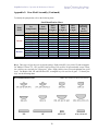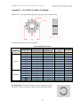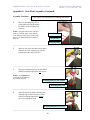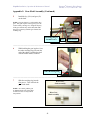
1
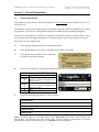
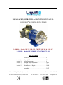
TM
INSTALLATION, OPERATION and MAINTENANCE MANUAL
ROTOGEAR® MAGNETIC-DRIVE PUMPS
3-SERIES:
Models 31F, 33F, 35R, 35F, 37R, 37F, 39R, 39F & 311F - MC
H-SERIES:
Models H3F, H5R, H5F, H7N, H7R & H7F - MC
Table of Contents
Section 1:
Section 2:
Section 3:
Section 4:
Section 5:
Forward . . . . . . . . . . . . . . . . . . . . . . . . . . . . . 2
General Information . . . . . . . . . . . . . . . . . . . 3-8
Safety Precautions . . . . . . . . . . . . . . . . . . . . 9
Pump & Motor Installation . . . . . . . . . . . . . . 10-12
Start-Up & Operation . . . . . . . . . . . . . . . . . . 13
Maintenance & Repair . . . . . . . . . . . . . . . . . 14-30
Appendix . . . . . . . . . . . . . . . . . . . . . . . . . . . . 31-47
© June 2005 Liquiflo, All rights reserved
443 North Avenue, Garwood, NJ 07027 USA
Document No.: 3.20.074
Tel: 908-518-0777
Fax: 908-518-1847
www.liquiflo.com
Rotogear® Magnetic-Drive Pumps
Models 31-39, 311 & H3-H7 - MC
Liquiflo Installation, Operation & Maintenance Manual
Forward
This manual provides instructions for the installation, operation and maintenance of the Rotogear® 3 & H
Series gear pumps, Mag-Drive Models 31F, 33F, 35R, 35F, 37R, 37F, 39R, 39F, 311F, H3F, H5R, H5F,
H7N, H7R & H7F. It is critical for any user to read and understand the information in this manual along
with any documents this manual refers to prior to installation and start-up.
Liquiflo shall not be liable for damage or delays caused by a failure to follow the instructions for
installation, operation and maintenance as outlined in this manual.
These pumps are not warranted for service other than those specified on the order by Liquiflo applications
engineering. If it is desirable to use this product for alternative services, please call Liquiflo applications
engineering or your local Liquiflo distributor.
Thank you for purchasing a Liquiflo product.
LIQUIFLO STANDARD TERMS AND CONDITIONS APPLY UNLESS SPECIFIED IN
WRITING BY LIQUIFLO.
Detailed Table of Contents
1. General Information
1.1
1.2
1.3
1.4
1.5
1.6
1.7
1.8
1.9
5. Maintenance & Repair
General Instructions . . . . . . . . . . . . . . . . . . . 3
Pump Specifications . . . . . . . . . . . . . . . . . . . 4-6
Model Coding . . . . . . . . . . . . . . . . . . . . . . . . 6
Pump Installation. . . . . . . . . . . . . . . . . . . . . . 7
Start-Up . . . . . . . . . . . . . . . . . . . . . . . . . . . . . 7
Operation & Troubleshooting . . . . . . . . . . . . 7
Maintenance & Repair. . . . . . . . . . . . . . . . . . 7
Repair Kits & Replacement Parts . . . . . . . . . 7
Returned Goods Authorization (RGA) . . . . . 8
2. Safety Precautions
2.1 General Precautions . . . . . . . . . . . . . . . . . . . 9
2.2 Precautions for Magnetic-Drive Pumps . . . . 9
3. Pump & Motor Installation
3.1
3.2
3.3
3.4
Installation of Pump, Motor and Base. . . . . . 10
General Piping Requirements . . . . . . . . . . . . 10
Gear Pump Requirements . . . . . . . . . . . . . . . 11
General Motor Requirements . . . . . . . . . . . . 11-12
3.4.1 Motor Selection. . . . . . . . . . . . . . . . . . 11
3.4.2 Motor Hook-Up. . . . . . . . . . . . . . . . . . 12
3.4.3 Motor Direction. . . . . . . . . . . . . . . . . . 12
4. Start-Up & Operation
4.1 Precautions Prior to Starting Pump . . . . . . . . 13
4.2 Operating Requirements . . . . . . . . . . . . . . . . 13
4.3 Troubleshooting. . . . . . . . . . . . . . . . . . . . . . . 13
2
5.1 Work Safety . . . . . . . . . . . . . . . . . . 14
5.2 Removal from System . . . . . . . . . . 14
5.3 Pump Disassembly . . . . . . . . . . . . . 15-19
Cartridge Removal . . . . . . . . . . . . . 15
Gear-Shaft Disassembly . . . . . . . . . 17-18
Removal of Bearing Lock Pins. . . . 18
Removal of Bearings . . . . . . . . . . . 18
Removal of Outer Magnet . . . . . . . 19
5.4 Pump Assembly . . . . . . . . . . . . . . . 20-30
A: Pump Cartridge Assembly . . . . . . 20-27
Internal Bearing Flush Option . . . . 20
Installation of Bearings. . . . . . . . . . 21
Installation of Wear Plates . . . . . . . 22-23
Installation of Inner Magnet . . . . . . 24-27
B: Outer Magnet-Motor Assembly . . 28-29
Outer Magnet Installation. . . . . . . . 29
C: Motor-Pedestal Assembly. . . . . . . 30
D: Cartridge Installation. . . . . . . . . . . 30
Appendix:
A-1:
A-2:
A-3:
A-4:
A-5:
A-6:
A-7:
Fastener Torque Specifications . . . . . . 31
Retaining Ring Tool Specifications. . . 32
Wear Allowances. . . . . . . . . . . . . . . . . 33-35
Pump Parts List . . . . . . . . . . . . . . . . . . 36
Gear-Shaft Assembly. . . . . . . . . . . . . . 37-41
Reference Drawings . . . . . . . . . . . . . . 42-45
Troubleshooting Guide . . . . . . . . . . . . 46-47
Liquiflo Installation, Operation & Maintenance Manual
Rotogear® Magnetic-Drive Pumps
Models 31-39, 311 & H3-H7 - MC
Section 1: General Information
1.1
General Instructions
This manual covers the 3-Series and H-Series Mag-Drive Close-Coupled pumps, Models 31 thru 39, 311,
and H3 thru H7.
The materials of construction of the pump are selected based upon the chemical compatibility of the fluid
being pumped. The user must verify that the materials are suitable for the surrounding atmosphere.
If the fluid is non-conductive, methods are available to mechanically ground the isolated shaft. This is
only necessary if the surrounding atmosphere is extremely explosive or stray static charges are present.
Upon receipt of your Liquiflo pump:
A)
Verify that the equipment has not been damaged in transit.
B)
Verify that the pump Serial Number is stamped on the pump's rear housing.
C)
Verify that the Liquiflo Stainless Steel Nameplate
is secured to the pump’s housing:
D)
For ATEX certification, verify that the following Stainless Steel Tag is attached to the pump:
Explanation of ATEX Tag
Group II
Category
2
Category
3
D
G
E)
Explosive atmospheres
Equipment provides a high level of
protection. Explosive atmospheres are
likely to occur.
Equipment provides a normal level of
protection. Explosive atmospheres are
unlikely to occur.
Dust
Gas
Record the following information for future reference:
Model Number:
Serial Number:
Date Received:
Pump Location:
Pump Service:
NOTE: By adding a K prior to the pump's Model Code, a Repair Kit can be obtained which consists of the
following parts: drive and idler gears, drive and idler shafts, wear plates, bearings, retaining rings, keys, housing
alignment pins, bearing lock pins and O-rings. (See Appendix 4 for more information.)
3
Rotogear® Magnetic-Drive Pumps
Models 31-39, 311 & H3-H7 - MC
Liquiflo Installation, Operation & Maintenance Manual
1.2
Pump Specifications
Table 1A: Performance Specifications (English System Units)
Pump
Series
3-Series
H-Series
Pump
Model
Max
Flow
Max
Speed
Max
∆P
Max
Viscosity (2)
NPSHR (3)
Dry Lift (3)
TD (4)
UNITS:
31F
33F
35R
35F
37R
37F
39R
39F
311F
H3F
H5R
H5F
H7N
H7R
H7F
GPM
0.48
1.45
2.41
3.38
8.59
10.7
15.1
21.5
21.5
1.45
2.41
3.38
5.37
8.59
10.7
RPM
1750
1750
1750
1750
1750
1750
1750
1750
1750
1750
1750
1750
1750
1750
1750
PSI
100
100
100
100
100
100
100
100
80
225 (1)
225 (1)
225 (1)
225 (1)
225 (1)
225 (1)
cP
100,000
100,000
100,000
100,000
100,000
100,000
100,000
100,000
100,000
100,000
100,000
100,000
100,000
100,000
100,000
ft
3
2
2
2
5.2
5.2
4
3
3
2
2
2
5.2
5.2
5.2
ft
0.5
1.5
2
4
6
7
6
14
14
1.5
2
4
6
6
7
GPR
.000276
.000828
.001379
.001930
.004910
.006140
.008610
.01228
.01228
.000828
.001379
.001930
.003070
.004910
.006140
Table 1B: Performance Specifications (SI System Units)
Pump
Series
3-Series
H-Series
Pump
Model
Max
Flow
Max
Speed
Max
∆P
Max
Viscosity (2)
NPSHR (3)
Dry Lift (3)
TD (4)
UNITS:
31F
33F
35R
35F
37R
37F
39R
39F
311F
H3F
H5R
H5F
H7N
H7R
H7F
LPM
1.83
5.48
9.13
12.8
32.5
40.7
57.0
81.3
81.3
5.48
9.13
12.8
20.3
32.5
40.7
RPM
1750
1750
1750
1750
1750
1750
1750
1750
1750
1750
1750
1750
1750
1750
1750
bar
6.9
6.9
6.9
6.9
6.9
6.9
6.9
6.9
5.5
15.5 (1)
15.5 (1)
15.5 (1)
15.5 (1)
15.5 (1)
15.5 (1)
mPas
100,000
100,000
100,000
100,000
100,000
100,000
100,000
100,000
100,000
100,000
100,000
100,000
100,000
100,000
100,000
m
0.9
0.6
0.6
0.6
1.6
1.6
1.2
0.9
0.9
0.6
0.6
0.6
1.6
1.6
1.6
m
0.15
0.46
0.6
1.2
1.8
2.1
1.8
4.3
4.3
0.46
0.6
1.2
1.8
1.8
2.1
LPR
.001045
.003134
.005220
.007306
.018586
.023242
.032592
.04648
.04648
.003134
.005220
.007306
.011621
.018586
.023242
NOTES:
1
2
3
4
Max ∆P (Differential Pressure) is derated to 125 PSI (8.6 bar) for viscosities < 10 cP (mPas).
Fluid viscosities > 150 cP (mPas) should use pumps with trimmed gears to reduce power consumption and
increase pump efficiency. High-viscosity fluids may require larger pumps with trimmed gears operating at
lower speeds. Consult factory.
NPSHR and Dry Lift are Specified @ Max Speed and 1 cP (mPas).
TD (Theoretical Displacement) is based on new pump operating @ Max Speed and ∆P = 0.
4
Rotogear® Magnetic-Drive Pumps
Models 31-39, 311 & H3-H7 - MC
Liquiflo Installation, Operation & Maintenance Manual
Table 2: Absolute Temperature & Pressure Ratings
Minimum
Operating
Temperature
Pump
Models
Pump
Series
UNITS:
3-Series
H-Series
Maximum
Operating
Temperature (1)
Maximum
Operating
Pressure (3)
°F
°C
°F
°C
PSIG
bar (g)
31F, 33F, 35R & 35F
-40
-40
500
260
300
20.7
37R, 37F, 39R, 39F & 311F
-40
-40
500
260
225
15.5
H3F, H5R & H5F
-40
-40
500
260
300
20.7
H7N, H7R & H7F
-40
-40
500
260
225
15.5
NOTES:
1
The actual maximum surface temperature depends not on the pump but primarily on the temperature of the
fluid being pumped. Temperature class can be controlled with the use of thermal sensors. Pump surfaces will
be approximately 20 °F (7 °C) above the temperature of the fluid being pumped.
2
Pump is designed to operate within the ambient temperature range of -4 °F (-20 °C) and 104 °F (40 °C).
3
For pumps with ANSI 150# RF Flanges, the Maximum Operating Pressure Rating of the flange is 285 PSIG
within the temperature range of -20 to 100 °F. Above 100 °F, derate by 0.29 PSIG/°F.
Table 3: Maximum Torque Specifications (in-lbs)
Parameter
3-Series
31F
33F
35R
35F
─
3
4
4
4
23
H3F
4
9
11
12
12
23
H5R
7
15
19
20
20
74
H5F
10
21
26
28
28
74
H-Series
Idler Gear Teflon
Idler Gear Carbon
Idler Gear Celcon/Delrin
Idler Gear PEEK
Idler Gear Ryton
Double Metal Gears
MCS
MCU
Magnetic Coupling MCA
Size
MCB
MCC
MCV
H7N
14
28
36
38
38
134
─
33
37R
37F
39R
39F
311F
H7R
22
45
57
61
61
189
─
H7F
27
56
71
76
76
189
─
38
79
99
107
107
189
─
54
113
142
153
153
189
─
─
─
54
113
142
153
153
189
─
─
─
75
66
120
─
─
─
─
240
200
Table 4: Weight Data
Parameter
Pump Weight *
3-Series
31F
33F
35R
35F
31
14
H3F
31
14
H5R
32
15
H5F
32
15
H-Series
* Weight of pump with threaded ports, excluding motor.
5
H7N
36
16
37R
37F
39R
39F
311F
H7R
36
16
H7F
36
16
38
17
40
18
40
18
Unit
lbs
kg
Rotogear® Magnetic-Drive Pumps
Models 31-39, 311 & H3-H7 - MC
Liquiflo Installation, Operation & Maintenance Manual
Table 5: Material Data
Component
Material(s)
Pump Housing
Mounting Hardware
Mounting Bracket (Pedestal)
Motor Frames (C-Face)
Bearings
Wear Plates
Gears
Shafts
Coating on Shafts
Housing Pins
Bearing Pins
Retaining Rings
Keys
O-rings
Magnetic Coupling
316 Stainless Steel, Alloy-20 or Alloy-C
18-8 Stainless Steel
Epoxy Painted Cast Iron
NEMA 56C/56HC, 143/145TC & 182/184TC; IEC 71/80/90 (B5 Flange)
Carbon, Carbon-60, Teflon, PEEK or Silicon Carbide (Note 1)
Carbon, Carbon-60, Teflon, PEEK or Ceramic (Note 1)
316 SS, Alloy-C, PEEK, Ryton, Celcon, Delrin, Teflon or Carbon (Note 1)
316 Stainless Steel or Alloy-C (Note 2)
None, Ceramic Chrome Oxide or Tungsten Carbide
316 Stainless Steel or Alloy-C (Note 2)
Teflon, 316 Stainless Steel or Alloy-C (Note 2)
316 Stainless Steel or Alloy-C (Note 2)
316 Stainless Steel or Alloy-C (Note 2)
Teflon, Viton, EPDM, Buna-N, Kalrez or 316 SS/PFA Encapsulated
MCS and MCA Magnets: Ceramic
MCU, MCB, MCC and MCV Magnets: Samarium Cobalt (SmCo)
Inner Magnet Casing: 316 Stainless Steel or Alloy-C (Note 2)
Outer Magnet Casing: Carbon Steel/Epoxy
NOTES:
1
2
3
Teflon is 25% glass-filled PTFE.
Metallic material will match pump housing material. (Exception: Note 3)
Alloy-20 pumps will have all metallic internal parts made from Alloy-C.
1.3
Model Coding
A fifteen-position Model Code is used to completely describe a specific mag-drive pump. This code is
required when ordering a new pump or a cartridge, repair kit or replacement parts for an existing pump.
The table below describes the Model Code and gives a specific example:
Table 6: Mag-Drive Pump Model Code Description & Example
Position
#
Description
1
2
3
4
5
6
7
8
9
10
11
12
13
14
15
Pump Model (Size)
Pump Model (Capacity)
Basic Material & Port Type
Drive Gear
Idler Gear
Wear Plates
Bearings
Outer Magnet Bore (Motor Frame)
Bearing Flush
Shaft Coating
O-rings
Retaining Rings
Bearing Pins
Magnetic Coupling
Options
Pump Model Code Example: 35FS6P22000000US
Code
Selection
35
F
S
6
P
2
2
0
0
0
0
0
0
U
S
Model 35F (35 = Pump Size; F = Full Capacity)
316 SS Housing and Shafts & NPT Ports
316 SS Drive Gear
PEEK Idler Gear
Carbon Wear Plates
Carbon Bearings
5/8” (NEMA 56C or 56HC Motor Frame)
No Bearing Flush
No Shaft Coating (Bare 316 SS Shafts)
Teflon O-rings
316 SS Retaining Rings
Teflon Bearing Pins
MCU (75 in-lbs) Magnetic Coupling
Single-Wall Containment Can
NOTE: See the Liquiflo Product Catalog or the Liquiflo Website (www.liquiflo.com) for complete Model Coding
information.
6
Liquiflo Installation, Operation & Maintenance Manual
1.4
Rotogear® Magnetic-Drive Pumps
Models 31-39, 311 & H3-H7 - MC
Pump Installation
During installation of the pump and supporting equipment, follow the guidelines given in Section 3. Pay
special attention to all cautionary notes in this section.
1.5
Start-Up
Before operating the pump, inspect the system as outlined in Section 4. Do not start the pump until the
inspection is satisfactory and all safety precautions have been taken.
1.6
Operation & Troubleshooting
The successful and safe operation of a pump is not only dependent on the pump but also on each of the
system components. It is therefore important to monitor the entire pumping system during operation and
to perform the necessary maintenance to keep the system running smoothly.
A normally operating magnetic-drive gear pump will deliver a steady, pulse-less flow with no leakage, be
relatively quiet and have a predictable flow rate based on the pump speed, fluid viscosity and differential
pressure across the pump. Refer to the performance curves of the specific pump model being operated
(see Liquiflo Product Catalog or website: www.liquiflo.com).
If a significant problem is observed during operation, the pump should be stopped so that corrective
action can be taken. The observed problem could have several possible causes, and multiple remedies for
each cause. For help with problem solving, refer to the Troubleshooting Guide given in Appendix 7.
1.7
Maintenance & Repair
The pump has internal bearings, wear plates, gears and shafts which require replacement over time due to
physical wear. The center housing of the pump may also incur physical wear and require replacement
(see Appendix 3). O-rings and retaining rings should always be replaced when rebuilding the pump.
Standard repair kits are available to facilitate repair of the pump (see Appendix 4). A repair kit includes
all internal wear parts as well as O-rings, retaining rings, bearing lock pins, housing alignment pins and
keys. The parts not included in a mag-drive pump repair kit are the housings (front, center and rear),
magnets (inner and outer), containment can, pedestal and hardware (bolts, nuts and washers).
Before performing maintenance on the pump, review the safety precautions given in Section 2. Removal
of the pump from the piping system is covered in Section 5.2. To disassemble the pump, follow the
procedure in Section 5.3. To replace parts and reassemble the pump, follow the assembly procedure in
Section 5.4. When performing maintenance, pay special attention to all cautionary notes given in these
sections.
1.8
Repair Kits & Replacement Parts
Repair kits and replacement parts for the pumps can be purchased from your local Liquiflo distributor.
Refer to Appendices 4 thru 6 for individual parts information.
7
Liquiflo Installation, Operation & Maintenance Manual
1.9
Rotogear® Magnetic-Drive Pumps
Models 31-39, 311 & H3-H7 - MC
Returned Goods Authorization (RGA)
If it is necessary to return the pump to the factory for service,
1) Contact your local Liquiflo distributor to discuss the return, obtain a Returned Goods
Authorization Number (RGA #) and provide the distributor with the required information
(see RGA Record below).
2) Clean and neutralize pump.
3) Package the pump carefully and include the RGA # in a visible location on the outside surface of
the box.
4) Ship pump to factory, freight prepaid.
Returned Goods Authorization (RGA) Record
1
RGA #
2
Distributor Name
3
Order Date
4
Customer PO#
5
Return Date
6
Item(s) Returned
7
Serial Number(s)
8
Reason for Return
9
Fluid(s) Pumped
10
Notes
(Supplied by Distributor)
NOTE: Pump must be cleaned and neutralized prior to shipment to the factory.
8
Liquiflo Installation, Operation & Maintenance Manual
Rotogear® Magnetic-Drive Pumps
Models 31-39, 311 & H3-H7 - MC
Section 2: Safety Precautions
2.1
General Precautions
•
Always lock out the power to the pump driver when performing maintenance on the pump
•
Always lock out the suction and discharge valves when performing maintenance on the pump
•
Never operate the pump without safety devices installed
•
Never operate the pump with suction and/or discharge valves closed
•
Never operate the pump out of its design specifications
•
Never start the pump without making sure that the pump is primed
•
Never use heat to disassemble pump
•
Inspect the entire system before start-up
•
Monitor the system during operation and perform maintenance periodically or as required by
the application
•
Decontaminate pump using procedures in accordance with federal, state, local and company
environmental regulations
•
Before performing maintenance on the pump, check with appropriate personnel to determine
if skin, eye or lung protection is required and how best to flush the pump
•
Pay special attention to all cautionary statements given in this manual. Failure to observe
safety precautions can result in personal injury, equipment damage or malfunction.
Cautionary statements will have the following format:
CAUTION! (Statement)
2.2
Precautions for Magnetic-Drive Pumps
Magnetic-drive pumps contain strong magnets, which pose health risks. Based on this the following must
be observed:
•
Individuals with cardiac pacemakers should avoid repairs on these units
•
Individuals with internal wound clips, metallic wiring, or other metallic prosthetic devices
should avoid repairs on these units
•
Strong magnetic fields can cause tools and parts to slam together, injuring hands and fingers
Strong magnets will attract iron, cast iron, carbon steel and some types of stainless steel. Keep magnets
away from credit cards, computers, computer discs and watches.
9
Liquiflo Installation, Operation & Maintenance Manual
Rotogear® Magnetic-Drive Pumps
Models 31-39, 311 & H3-H7 - MC
Section 3: Pump & Motor Installation
3.1
Installation of Pump, Motor and Base
Refer to the Hydraulic Institute Standards for proper installation procedures of the base, pump and motor.
Observe the following guidelines:
1)
The foundation area must be rigid and level for maintaining pump alignment.
2)
The pump and motor assembly must be securely fastened to the base, and the base must be
securely attached to the ground.
3)
The pump inlet should be as close to the liquid source as practical and preferably below it.
4)
The pump and motor should be accessible for servicing and inspection.
5)
The pump and motor should be cleaned periodically to prevent the build-up of dust.
NOTE: The pump models covered in this manual are close-coupled and no alignment procedure between
the pump and motor is required.
3.2
General Piping Requirements
Guidelines for piping are given in the Hydraulic Institute Standards and should be reviewed prior to pump
installation.
1)
All piping must be supported independently and must line up naturally with pump ports.
CAUTION! Do not use the pump to support the piping or allow the piping
to apply stress to the pump ports. This can distort the alignment of the
pump housing with internal parts and lead to rapid wear or malfunction.
2)
DO NOT make final connection of piping to pump until the grout has hardened and the pump and
motor hold-down bolts have been tightened.
3)
Piping that handles both hot and cold liquids require proper installation of expansion loops and
joints so that thermal expansion of the piping will not cause misalignment.
4)
Gasket installation and materials must be suitable for the service.
5)
Piping runs should be designed to minimize friction losses.
6)
Suction and discharge piping should be the same size or larger than the inlet and outlet ports.
7)
The piping should be arranged to allow the pump to be flushed and drained prior to the removal
of the pump for servicing. Valves and unions should be installed to allow the pump to be isolated
during maintenance.
8)
The piping system should be thoroughly cleaned prior to installation of the pump.
10
Liquiflo Installation, Operation & Maintenance Manual
Rotogear® Magnetic-Drive Pumps
Models 31-39, 311 & H3-H7 - MC
3.3
Gear Pump Requirements
1)
A positive displacement pump should have a pressure relief valve installed in the discharge line.
The relief valve should be the closest valve to the discharge port of the pump and should bypass
the discharge line back to the supply tank.
2)
The maximum particle size capable of being passed by the pumps is 37 microns. When pumping
fluids containing solids, a filter of at least 400 U.S. Mesh should be installed in the suction line.
3)
Concentration of solids should be limited to a maximum of 1%. Exceeding 1% can cause the
wear rate to increase to an unacceptable level, resulting in a rapid decrease in pump performance.
In addition to solids concentration, the specific wear rate also depends on the size, shape and
hardness of the particles, the operating speed and the materials used to construct the pump.
3.4
General Motor Requirements
1)
The motor must be compatible with the pump and conditions of the application.
2)
The motor supply voltage must match the nameplate voltage of the motor.
3)
The motor should never be operated outside of its design specifications.
4)
The motor should be inspected periodically and serviced or replaced as required.
CAUTION! Lock out power to the motor before servicing or replacing.
3.4.1
Motor Selection
1)
The motor frame must be compatible with the pump mounting bracket. Choices are NEMA 56C,
56HC, 143TC, 145TC, 182TC & 184TC, and IEC 71, 80 & 90 (B5 flange). NEMA 182/184TC
motor frames will require an adapter plate (P/N SP0046) and four adapter mounting bolts (P/N
641105) to mount the motor to the bracket (see Page 29). (Note: Complete pumps ordered for
use with NEMA 182/184TC motor frames will be supplied with the adapter plate and adapter
mounting bolts.)
2)
The motor must have an enclosure that is compatible with the application conditions. If an
explosion-proof motor is required, the temperature code of the motor must be acceptable for the
fluid that will be pumped.
3)
The speed and power output rating of the motor must be sufficient for the conditions of service.
The power output rating of the motor should exceed the maximum power that will be required by
the pump over its operating range.
11
Rotogear® Magnetic-Drive Pumps
Models 31-39, 311 & H3-H7 - MC
Liquiflo Installation, Operation & Maintenance Manual
3.4.2
Motor Hook-Up
1)
Electrical wiring of the motor should be performed by a certified electrician.
2)
Follow the recommendations of the motor manufacturer and observe all electrical wiring safety
standards.
3)
The motor supply voltage must match the motor nameplate voltage or serious motor damage or
fire can result.
CAUTION! Lock out power to the motor before connecting to power line.
3.4.3
Motor Direction
The motor shaft is magnetically coupled to the drive shaft of the pump. Both shafts will turn in the same
direction. Because the gear pump is bi-directional, the pump shaft can turn in either direction to produce
flow in either direction. The direction of rotation of the motor shaft (same as that of the pump drive shaft)
will determine which side of the pump is the inlet (suction side) and which side is the outlet (discharge
side). For the pump models covered in this manual, the flow direction will be as shown below:
Idler Gear
Idler Shaft
Flow
INLET
OUTLET
Flow
Drive Shaft
Flow
Flow
INLET
Drive Gear
Counterclockwise Rotation of Motor Shaft:
Clockwise Rotation of Motor Shaft:
Fluid will enter the pump at the left side (inlet)
and be discharged at the right side (outlet).
Fluid will enter the pump at the right side (inlet)
and be discharged at the left side (outlet).
12
Liquiflo Installation, Operation & Maintenance Manual
Rotogear® Magnetic-Drive Pumps
Models 31-39, 311 & H3-H7 - MC
Section 4: Start-Up & Operation
4.1
Precautions Prior to Starting Pump
1)
Verify that the pump and motor are suitable for the conditions of service.
2)
Verify that all suction and discharge valves are open before starting the pump.
3)
Prime the pump and jog the motor to check the rotation. As viewed from the pump end, a
clockwise rotation of the motor will result in fluid discharge to the left; counterclockwise rotation
will result in fluid discharge to the right (see Page 12).
4)
The pump is capable of pulling a dry lift, but it is still recommended that the pump be primed
prior to starting.
5)
A pressure relief valve should be installed in the discharge line to protect the pump from any
kind of line blockage including the inadvertent closing of an isolation valve.
6)
If the fluid contains suspended solids, a filter of at least 400 U.S. Mesh should be installed in the
suction line. Concentration of solids should be limited to a maximum of 1%.
7)
Ensure that all safety devices are installed before operating pump.
4.2
Operating Requirements
1)
Do not operate the pump without fluid inside it.
CAUTION! Do not run pump dry for more than
30 seconds or damage to internal parts can result.
2)
The pump should be operated with at least 20 PSI (1.4 bar) differential pressure to ensure that
internal components are properly lubricated by the pumped fluid.
3)
Adequate suction pressure must be available for the pump to function properly (see NPSHR data
on Page 4).
4)
Do not operate the pump outside of its design specifications (See Pages 4 and 5).
4.3
Troubleshooting
During pump operation, inspect for:
(1) Unusual noise
(2) Product leakage
(3) Expected suction and discharge pressures
(4) Product flow
If any problems are encountered with the above items, stop the pump and take corrective action. For help
with troubleshooting, refer to Appendix 7.
13
Liquiflo Installation, Operation & Maintenance Manual
Rotogear® Magnetic-Drive Pumps
Models 31-39, 311 & H3-H7 - MC
Section 5: Maintenance & Repair
The pump has internal bearings, wear plates, gears and shafts which require replacement over time due to
physical wear. The center housing of the pump may also incur physical wear and require replacement
(see Appendix 3). O-rings and retaining rings should always be replaced when rebuilding the pump.
5.1
Work Safety
Before performing maintenance, review the safety precautions given in Section 2 (see Page 9).
CAUTION! The Magnetic Couplings used in these pumps are extremely powerful.
Observe the precautions given in Section 2.2.
5.2
Removal from System
Before servicing, prepare the pump as follows:
CAUTION! If the pump was used to move hazardous or toxic fluids, it must be
flushed and decontaminated prior to removal from the system piping. Refer to
the Material Safety Data Sheet (MSDS) for the liquid and follow all prescribed
safety precautions and disposal procedures.
1
Flush the pump.
2
Stop the motor and lock out the electrical panel.
CAUTION! Be certain the pump’s motor switch is in the OFF position and the
power to the motor is locked out.
3
Close the suction and discharge isolation valves.
4
Disconnect the pump from the system piping.
5
Drain the containment can by removing the 1/8” NPT plug on the pump’s front housing (see
photo below).
Location & Removal of Drain Plug
To drain the containment can, remove the
1/8” NPT plug that is located near the
bottom of the pump’s front housing
(see photo).
1/8” NPT Plug
14
Liquiflo Installation, Operation & Maintenance Manual
5.3
Rotogear® Magnetic-Drive Pumps
Models 31-39, 311 & H3-H7 - MC
PUMP DISASSEMBLY
Follow the procedure below and refer to the drawings in Appendix 6.
_____________________________________________________________________________________
Cartridge Removal:
1
Remove the four front housing bolts (27)
from the pedestal (16).
Pedestal
_____________________________________________________________________________________
2
Pinch Point
Carefully pull the Cartridge straight out.
CAUTION! Do not place hands
or fingers between Pedestal and
Pump Cartridge.
NOTE: Force must be applied to overcome the magnetic
attraction between the outer and inner magnets. (See Page
20 for information on the Pump Cartridge.)
Cartridge
_____________________________________________________________________________________
3
Remove six screws (18) and separate the containment can (12) from the front housing (8).
Discard the containment can O-ring (19).
Front
Housing
Containment Can
O-ring
_____________________________________________________________________________________
15
Rotogear® Magnetic-Drive Pumps
Models 31-39, 311 & H3-H7 - MC
Liquiflo Installation, Operation & Maintenance Manual
4
Detach the inner magnet (11) from the drive
shaft (20) by removing the outer retaining
ring (28). Remove the retaining ring by
inserting a pointed tool in the split and
prying off.
Retaining Ring
in Outer Groove
CAUTION! Be careful not to damage the shaft.
NOTE: After removal of the retaining ring, any high spots on
the end of the shaft must be polished smooth so that free removal
of the inner magnet is not inhibited.
_____________________________________________________________________________________
5
Remove the inner magnet and key (13)
from the drive shaft.
Key
Inner Magnet
_____________________________________________________________________________________
6
Dislodge the retaining ring (28) from the
inner groove on the drive shaft.
CAUTION! Be careful
not to damage the shaft.
NOTE: The retaining ring can be dislodged from
the inner groove by using a large flat screwdriver
and a rigid bar, as shown.
Dislodging Retaining
Ring from Inner Groove
_____________________________________________________________________________________
7
Slide the retaining ring up the shaft and into
outer groove. Then pry the retaining ring
out of the groove and remove.
CAUTION! Be careful
not to damage the shaft.
NOTE: The retaining ring can be dislodged from
the outer groove by using a large flat screwdriver
and a rigid block, as shown.
Dislodging Retaining
Ring from Outer Groove
_____________________________________________________________________________________
16
Rotogear® Magnetic-Drive Pumps
Models 31-39, 311 & H3-H7 - MC
Liquiflo Installation, Operation & Maintenance Manual
8
Remove the four housing bolts (4) and then
separate the rear, center and front housings.
Rear Housing
Center Housing
Front Housing
_____________________________________________________________________________________
9
Remove the wear plates (7) and the
gear-shaft assemblies. Remove the
O-rings (5) from the center housing (21)
and discard.
Gear-Shaft
Assemblies
Wear
Plates
NOTE: Liquiflo Repair Kits come with the gears
and shafts preassembled, as shown in Appendix 4.
If you are using a repair kit to rebuild the pump, it
is not necessary to separate the gears from the shafts.
If this is the case, skip Step 10 and proceed directly
to Step 11.
Center Housing
_____________________________________________________________________________________
Gear-Shaft Disassembly:
10
CAUTION! Be careful not to damage
the drive and idler shafts.
Retaining
Ring
a. Remove one retaining ring (28)
from the shaft (1 or 20).
NOTE: Use special vice jaws made of aluminum,
bronze, brass or other soft material so as not to
dent or damage the shaft (see photo at right).
Soft Jaws
b. Separate the gear (6 or 22) and
Key
key (23B or 23A) from the shaft.
Shaft
Other Retaining Ring
Gear
17
Rotogear® Magnetic-Drive Pumps
Models 31-39, 311 & H3-H7 - MC
Liquiflo Installation, Operation & Maintenance Manual
c.
Remove the other
retaining ring (28)
from the shaft.
Drive
GearShaft
Parts
NOTE: One method for removing
the retaining ring is shown at right.
First bridge the shaft with a close
fitting open-end wrench and then
strike the wrench handle with a
mallet to dislodge the retaining
ring from the groove (see photo).
Idler GearShaft Parts
_____________________________________________________________________________________
Removal of Bearing Lock Pins:
11
Remove the bearing lock pins (25) from
the front and rear housings.
NOTE: If the pins are made of Teflon, a pointed
tool can be used to extract them, as shown. If the
pins are metallic, the bearings should be removed
first (see Step 12).
Rear
Housing
_____________________________________________________________________________________
Removal of Bearings:
Most bearings for these pumps were designed to have a light press fit into the front and rear housings.
Removal is generally accomplished by destroying the bearings. The bearings can be pulled out using a
hooked tool (see Photos 12a and 12b). Plastic bearings, such as Teflon, can also be extracted by using a
tap that is slightly larger than the bearing inner diameter (see Photo 12c).
12
Remove the bearings (3A and 3B) from the front and rear housings.
CAUTION! Be careful not to damage the housing bores when removing the bearings.
12a
12b
12c
_____________________________________________________________________________________
18
Rotogear® Magnetic-Drive Pumps
Models 31-39, 311 & H3-H7 - MC
Liquiflo Installation, Operation & Maintenance Manual
Removal of Outer Magnet:
13
a. Detach the motor (with outer magnet)
Pedestal
from the pedestal (16) by removing
four bolts (15).
NOTE: The pedestal is shown connected directly
to a motor, but the pedestal could also be connected
directly to the Liquiflo S-Adapter (P/N SADAPT) or
the Liquiflo Power Frame (P/N A-620804). Each of
these devices can be used to long-couple the magdrive pump to the motor. If either of these devices
are being used, the outer magnet will be installed not
on the motor shaft, but on the shaft of the device.
(See the Liquiflo Product Catalog or the Liquiflo
Website for more information on the S-Adapter or
Power Frame.)
b. Loosen the two setscrews (17) on the
Outer Magnet
hub (33) of the outer magnet (10).
Setscrew
Hub
c. Remove the outer magnet from the
motor shaft.
END OF DISASSEMBLY PROCEDURE
19
Rotogear® Magnetic-Drive Pumps
Models 31-39, 311 & H3-H7 - MC
Liquiflo Installation, Operation & Maintenance Manual
5.4
PUMP ASSEMBLY
Follow the procedure below and refer to the drawings in Appendix 6.
Part A: Pump Cartridge Assembly
A Pump Cartridge is a complete mag-drive pump less the
outer magnet and pedestal (see photo at right). A cartridge
replacement is a convenient way to quickly replace a pump
that requires maintenance. Pump cartridges are available
from the factory and are designated by placing a C in front
of the pump model code.
Example:
Pump Model Code: 35FS6P22100000US
Cartridge Model Code: C35FS6P22100000US
1
Place the front housing (8) and rear housing (2)
on a flat surface with the bearing bores facing
up. Install the 1/8” NPT plug (9) into the front
housing.
NOTE: Standard housings (i.e., not containing bearing
flush grooves) are shown at right. Teflon tape should
be applied to the threads of the drain plug to prevent
leakage.
Drain Plug
Internal Bearing Flush Option
Pumps ordered with the Internal
Bearing Flush (IBF) option will
have modified front and rear
housings, as shown at right. The
purpose of the IBF option is to
more effectively lubricate and
cool the bearings when pumping
extremely thin or extremely thick
liquids. When assembling the
pump, the IBF grooves must be
oriented on the higher pressure
discharge side of the pump.
Internal Bearing Flush (IBF) Grooves
Lower
Pressure
Suction
Side
Rear Housing
Front Housing
20
Higher
Pressure
Discharge
Side
Liquiflo Installation, Operation & Maintenance Manual
Rotogear® Magnetic-Drive Pumps
Models 31-39, 311 & H3-H7 - MC
Installation of Bearings into Front and Rear Housings:
2
Insert bearings (3A & 3B) into the housing bores, while aligning the grooves for the bearing lock
pins.
NOTE: If the bearings have not yet been removed from the
front and rear housings, refer to Step 12 of the disassembly
procedure (see Page 18). The bearings normally require a
light press fit to insert them into the housings. A mechanical
press can be used to facilitate this process (see photos).
Bearing
_____________________________________________________________________________________
3
Insert the bearing lock pins (25) into
the front and rear housings.
NOTE: The pins serve to prevent the bearings
from rotating. They are normally made of Teflon.
Metallic pins are available for high temperature
applications.
Bearing Lock Pins
_____________________________________________________________________________________
4
Insert two housing alignment
pins (24) into the front housing,
as shown.
Housing Alignment Pins
NOTE: The pins should have a slip fit into the
housing. The housing pins serve to accurately
align the front, center and rear housings.
_____________________________________________________________________________________
21
Liquiflo Installation, Operation & Maintenance Manual
5
Rotogear® Magnetic-Drive Pumps
Models 31-39, 311 & H3-H7 - MC
Install housing O-rings (5) into
the racetrack shaped grooves of
the center housing (21).
O-rings
CAUTION! Do not
reuse O-rings.
_____________________________________________________________________________________
6
Place the center housing (21)
onto the front housing (8) with
orientation as shown.
NOTE: Make certain the center
housing seats properly over the
housing alignment pins in the
front housing.
Center Housing
Front Housing
Installation of Wear Plates
Most Liquiflo wear plates are manufactured
with cut-outs or grooves to provide liquid
relief paths to reduce hydraulically induced
gear separation forces that exist during pump
operation. These forces decrease pump life
by placing significant loads on the shafts and
bearings. To be effective, the relief grooves
must face toward the gears.
Relief Grooves
NOTE: Failure to orient the wear plates
properly will reduce the operating life of
the pump.
22
Liquiflo Installation, Operation & Maintenance Manual
7
Rotogear® Magnetic-Drive Pumps
Models 31-39, 311 & H3-H7 - MC
Place two wear plates (7)
into position, as shown.
NOTE: If the wear plates are relieved,
the relief grooves must face up (see photo).
This will orient the grooves toward the
gears.
Wear Plates
Relief Grooves
facing up
_____________________________________________________________________________________
8
Insert the gear-shaft assemblies
into the housing, as shown.
NOTE: Liquiflo Repair Kits contain the gears and shafts
preassembled, as shown below. If the gears and shafts are
not assembled, see Appendix 5 for the assembly procedure.
Drive GearShaft Assembly
Idler GearShaft Assembly
_____________________________________________________________________________________
9
Wear Plates with Relief
Grooves facing down
Place two wear plates (7) on top of
the gears, as shown.
NOTE: If the wear plates are relieved, the
relief grooves must face down, toward the
gears.
10
Insert two housing alignment pins (24)
into the center housing (21).
Housing Alignment Pins
_____________________________________________________________________________________
23
Rotogear® Magnetic-Drive Pumps
Models 31-39, 311 & H3-H7 - MC
Liquiflo Installation, Operation & Maintenance Manual
11
Place the rear housing (2) on the center
housing (21).
Rear
Housing
NOTE: Make sure the rear housing seats properly over
the alignment pins. If the rear housing has an Internal
Bearing Flush (IBF) groove, the groove must be on the
discharge side of the pump (see bottom of Page 20).
12
Install four sets of bolts (4), nuts (29)
and lockwashers (30) into the housing;
then tighten the bolts.
NOTE: Apply anti-seize compound to the bolts. Refer to Appendix 1 for the torque specifications of the fasteners.
When tightening the housing bolts, use a star pattern torque sequence on the fasteners to ensure even compression
on the O-ring’s surface. With Teflon O-rings, repeat this process several times, waiting between retightening. This
is necessary because the Teflon will cold flow and require a certain amount of time to properly seat. Continue the
process until the bolts no longer require retightening.
_____________________________________________________________________________________
13
Turn the assembly over and install the
containment can O-ring (19) into the
circular groove on the front housing.
O-ring
CAUTION! Do not reuse O-rings.
Retaining Rings & Key
_____________________________________________________________________________________
Installation of Inner Magnet:
14
Install retaining ring (28) onto the drive shaft (20),
in the groove that is closest to the front housing
(inner groove). This can be done as follows:
CAUTION! Be careful not to damage
the drive shaft during this process.
a. Tap the retaining ring onto the end of the shaft
using a rubber mallet.
Retaining Ring on end of Drive
Shaft, above Outer Groove
______________________________________________________________________________
24
Rotogear® Magnetic-Drive Pumps
Models 31-39, 311 & H3-H7 - MC
Liquiflo Installation, Operation & Maintenance Manual
b. Push the retaining ring into the outer groove.
c. Tap the retaining ring down and out of the outer groove by using either:
[A] a rubber mallet and specially made tool (see Appendix 2), or
[B] a rubber mallet and open-end wrench that is slightly larger than the shaft diameter.
Step 14c:
Either Method
can be used
A
B
Retaining Ring Tool
Open-end Wrench
______________________________________________________________________________
d. Push the retaining ring down the shaft and into the inner groove.
CAUTION!
Be careful not
to scrape or
gouge the
drive shaft.
NOTE: Polish out any
rough marks on shaft
using very fine sandpaper or polishing cloth.
Retaining Ring
in Inner Groove
_____________________________________________________________________________________
15
Insert key (13) into the drive shaft (20).
Key
NOTE: The straight edge of the key should
be parallel to the drive shaft when installing
the inner magnet on the shaft.
Outer
Groove
_____________________________________________________________________________________
25
Liquiflo Installation, Operation & Maintenance Manual
Rotogear® Magnetic-Drive Pumps
Models 31-39, 311 & H3-H7 - MC
Inner Magnet Installation
Three kinds of inner magnets can be used in the pumps, as shown below. The axial positioning of the
inner magnet is automatically set by snap (retaining) rings installed on the drive shaft. The snap rings and
key serve to lock the inner magnet on the shaft.
_____________________________________________________________________________________
I.
MCS, MCB & MCV Inner Magnets:
The rounded edge of the inner magnet
must face the front housing.
(See diagram at right.)
_____________________________________________________________________________________
II.
MCU Inner Magnet:
The hub of the inner magnet must
face away from the front housing.
(See diagram at right.)
_____________________________________________________________________________________
III.
MCA & MCC Inner Magnets:
The counter-bore of the inner magnet
must face the front housing.
(See diagram at right.)
NOTE: These inner magnets require
longer drive shafts than those of the
other magnets shown above.
26
Rotogear® Magnetic-Drive Pumps
Models 31-39, 311 & H3-H7 - MC
Liquiflo Installation, Operation & Maintenance Manual
16
Slide the inner magnet (11) onto the
drive shaft (20) until it contacts the
retaining ring in the inner groove.
Inner
Magnet
NOTE: Install inner magnet with orientation as
described on Page 26.
17
Install the second retaining ring (28)
into the outer groove, as shown.
Retaining
Ring
NOTE: Use a rubber mallet, as shown, to tap the
retaining ring into the outer groove. This will lock
the inner magnet assembly on the drive shaft.
_____________________________________________________________________________________
18
Turn the inner magnet (11) by hand to
ensure free rotation of the gears.
NOTE: During this check, the gears can be
viewed thru the ports of the pump (see photo).
Gears visible thru Port
_____________________________________________________________________________________
19
Verify that the containment can O-ring is installed (see Step 13, Page 24); then attach the
containment can (12) to the pump housing using six sets of bolts (18) and lockwashers (32).
This completes the Pump Cartridge assembly.
Containment
Can
Pump Cartridge
NOTE: Apply anti-seize compound to the bolts. Refer to Appendix 1 for the torque specifications of the fasteners.
When tightening the containment can bolts, use a star pattern torque sequence on the fasteners to ensure even
compression on the O-ring’s surface. With Teflon O-rings, repeat this process several times, waiting between
retightening. This is necessary because the Teflon will cold flow and require a certain amount of time to properly
seat. Continue the process until the bolts no longer require retightening.
_____________________________________________________________________________________
27
Liquiflo Installation, Operation & Maintenance Manual
Rotogear® Magnetic-Drive Pumps
Models 31-39, 311 & H3-H7 - MC
Part B: Outer Magnet-Motor Assembly
The axial positioning of the outer magnet on the motor shaft is critical to pump performance. Improper
positioning can cause the outer magnet to rub against the front housing or produce an axial load on the
inner magnet, causing premature pump wear. Improper positioning can also cause the outer and inner
magnets to decouple. Refer to the diagrams on Page 29 when positioning the outer magnet.
20
Install the outer magnet as follows:
a. Insert motor key into the keyway on
the motor shaft.
b. Apply a small amount of anti-seize
compound to the motor shaft.
c. Align keyway of the outer magnet’s
hub (33) with the key on the motor
shaft.
d. Slide the outer magnet (10) onto the
motor shaft and position the hub as
shown on Page 29.
e. Tighten the two setscrews (17) on
the hub.
_____________________________________________________________________________________
Outer Magnet & Pedestal Part Numbers:
The specific outer magnet and pedestal supplied with the pump is dependent on the motor frame selected;
the outer magnet also depends on the magnetic coupling size (see table below). The pump Model Code
defines both the Outer Magnet Bore (Motor Frame) and the Magnetic Coupling (see Table 6, Page 6).
Motor Shaft Diameter or
Outer Magnet Bore Size
Outer Magnet
Part Number
Pedestal
Part Number
NEMA 56C or 56HC
5/8 in.
SOMCX-5
SP000
NEMA 143TC or 145TC
7/8 in.
SOMCX-7
SP000
NEMA 182TC or 184TC
1-1/8 in.
SOMCX-9
SP000 *
IEC 71 (B5 Flange)
14 mm
SOMCX-71
SP001
IEC 80 (B5 Flange)
19 mm
SOMCX-80
SP002
IEC 90 (B5 Flange)
24 mm
SOMCX-90
SP002
Standard Motor Frame
X = S, U, A, B, C or V (Magnetic coupling size; see Table 3, Page 5.)
* Adapter plate required (see Page 29).
_____________________________________________________________________________________
28
Liquiflo Installation, Operation & Maintenance Manual
Rotogear® Magnetic-Drive Pumps
Models 31-39, 311 & H3-H7 - MC
Outer Magnet Installation
The procedure for installing the outer magnet on the motor shaft is dependent on which motor frame is
used with the pump. The four standard cases are described below:
_____________________________________________________________________________________
I.
NEMA 56C & 56HC Frames: The end
of the motor shaft must be flush with the
inner surface of the outer magnet’s hub.
(See diagram at right.)
_____________________________________________________________________________________
II.
NEMA 143TC & 145TC Frames: The
motor shaft must protrude past the inner
surface of the outer magnet’s hub by
1/16 in. (1.6 mm).
(See diagram at right.)
_____________________________________________________________________________________
III.
IEC 71, 80 & 90 Frames: The outer
magnet's hub is positioned by a snap ring
installed in the hub. The end of the motor
shaft must contact the snap ring.
(See diagram at right.)
NOTE: The IEC motor must have a B5 Flange, as
shown, to be compatible with the pump mounting
bracket.
_____________________________________________________________________________________
IV.
NEMA 182TC & 184TC Frames: An
adapter plate is required to mount the
motor to the pedestal. The outer magnet’s
hub is positioned by a snap ring installed
in the hub. The end of the motor shaft
must contact the snap ring.
(See diagram at right.)
NOTE: Complete pumps ordered for use with
NEMA 182/184TC motor frames will be supplied
with the adapter plate (P/N SP0046) and adapter
mounting bolts (P/N 641105).
29
Liquiflo Installation, Operation & Maintenance Manual
Rotogear® Magnetic-Drive Pumps
Models 31-39, 311 & H3-H7 - MC
Part C: Motor-Pedestal Assembly
21
Install the motor (with outer magnet) to
the pedestal (16) using four sets of bolts
(15) and lockwashers (34).
NOTE: The C-faces of the motor and pedestal
should mate freely and mount flush. Refer to
Appendix 1 for the torque specifications of
the fasteners.
_____________________________________________________________________________________
Part D: Cartridge Installation
22
Pinch Point
CAUTION! Do not place
hands or fingers between
Pedestal and Cartridge. The
Outer and Inner Magnets will
suddenly pull together with
significant force.
Carefully install the pump cartridge
to the pedestal (16) using four sets
of bolts (27), nuts (26) and lockwashers (31).
SLOWLY
NOTE: Hold the pump cartridge firmly as shown above and then slowly move the containment can inside the outer
magnet. The faces of the pedestal and cartridge will mount flush. Refer to Appendix 1 for the torque specifications
of the fasteners.
END OF ASSEMBLY PROCEDURE
30
Liquiflo Installation, Operation & Maintenance Manual
Rotogear® Magnetic-Drive Pumps
Models 31-39, 311 & H3-H7 - MC
Appendix 1: Fastener Torque Specifications
Maximum Torque Specifications for 18-8 Stainless Steel Bolts
Function
Housing
Assembly
Containment
Can
Assembly
PumpPedestal
Assembly
Motor1Pedestal
Assembly
Motor2Adapter
Assembly
Adapter2Pedestal
Assembly
1
2
Pump Models
Bolt Size
Bolt
Type
Qty.
Max Torque
Specifications
(per
Pump)
(in-lbs)
(N-m)
31F, 33F, H3F
10-32 UNF x 1 ½
HHCS
4
31
3.5
35R, 35F, H5R,
H5F
10-32 UNF x 1.80
HHCS
4
31
3.5
37R, H7N, H7R
1/4-20 UNC x 2 ¼
HHCS
4
75
8.5
37F, H7F
1/4-20 UNC x 2 ½
HHCS
4
75
8.5
39R
1/4-20 UNC x 3
HHCS
4
75
8.5
39F, 311F
1/4-20 UNC x 3 ¾
HHCS
4
75
8.5
1/4-28 UNF x 5/8
HHCS
6
94
10.6
3/8-16 UNC x 1 ¼
HHCS
4
236
26.7
3/8-16 UNC x 1
HHCS
4
236
26.7
1/2-13 UNC x 1
SHCS
4
517
58.4
3/8-16 UNC x 1
HHCS
4
236
26.7
31F thru 39F,
311F,
H3F thru H7F
31F thru 39F,
311F,
H3F thru H7F
31F thru 39F,
311F,
H3F thru H7F
31F thru 39F,
311F,
H3F thru H7F
31F thru 39F,
311F,
H3F thru H7F
NEMA 56C, 56HC, 143TC & 145TC motor frames
NEMA 182TC & 184TC motor frames
HHCS = Hex Head Cap Screw
SHCS = Socket Head Cap Screw
31
Rotogear® Magnetic-Drive Pumps
Models 31-39, 311 & H3-H7 - MC
Liquiflo Installation, Operation & Maintenance Manual
Appendix 2: Retaining Ring Tool Specifications
The following tool is recommended for the efficient and safe installation or removal of the retaining rings
used in the pump. It should be manufactured from a hard material, such as steel.
Tool Dimensional Specifications (inches)
Tool #
1
2
3
For Pump Models
31F, 33F, 35R, 35F & H3F
37R, 37F, 311F, H5R & H5F
39R, 39F, H7N, H7R & H7F
ID
ID Tolerance
.378
.503
.628
+/- .001
+/- .001
+/- .001
Do Not
Chamfer
Inside
Edges
NOTE: The retaining ring tool is especially useful when assembling the gears on the drive and idler
shafts (see Appendix 5). It can also be used to facilitate installation of the inner magnet on the
drive shaft (see Section 5.4, Page 25).
32
Liquiflo Installation, Operation & Maintenance Manual
Rotogear® Magnetic-Drive Pumps
Models 31-39, 311 & H3-H7 - MC
Appendix 3: Wear Allowances
When a pump requires maintenance, a convenient way to restore the pump to like-new condition is to use
a repair kit. The repair kit contains all internal wear parts as well as O-rings, retaining rings, bearing lock
pins, housing alignment pins and keys.
In some cases, only certain parts may need to be replaced. The primary wear parts of the pump are the
gears, shafts, wear plates and bearings. The center housing (secondary wear part) may also incur physical
wear by contact with the gears caused by excessively worn bearings. (Note: the center housing is not
included in a standard repair kit.) These wear parts can be reused if they are in acceptable condition.
O-rings and retaining rings should not be reused. The following used parts should be inspected and
evaluated for reuse based on the specifications given in the Wear Allowances Chart (see Page 35):
Gears: Spur gears should have a uniform tooth profile on both the leading and trailing edges. If the
outer diameter of the gear is worn, pumping performance will degrade. Gears with minor wear should be
evaluated for reuse by measuring the outer diameter and comparing it to the minimum diameter
specification given in the Wear Allowances Chart. Gears with obvious major wear, such as flattened
teeth or other significant wear on the profile, should be replaced (see photo below).
New Gear
Extremely Worn Gear
Shafts: The area of the shaft that is engaged in the bearings will wear over time depending on the service
conditions and materials of construction (see photos below). Hard-coated shafts are available to minimize
or eliminate wear of the shaft surfaces. Worn shafts may allow the gears to contact the center housing
and accelerate both gear and center housing wear. The shaft journal area should be round and have a
minimum diameter as specified in the Wear Allowances Chart.
Idler Shaft
Drive Shaft
Areas of Bearing Engagement
33
Rotogear® Magnetic-Drive Pumps
Models 31-39, 311 & H3-H7 - MC
Liquiflo Installation, Operation & Maintenance Manual
Appendix 3: Wear Allowances (Continued)
Wear Plates: This is a sacrificial part of the pump designed to protect the front and rear housings from
wear by continual contact with the sides of the gears. Erosion of the wear plates increase clearances
causing slip to increase. This results in a reduction in pump performance. Wear plates should have
smooth surfaces and meet the minimum thickness requirements given in the Wear Allowances Chart.
(Note: Most Liquiflo wear plates are manufactured with cut-outs or relief grooves to minimize
hydraulically induced gear separation forces during pumping. These relieved wear plates increase pump
life by reducing loads on bearings and shafts. A typical relieved wear plate is shown below.)
Flat &
smooth
surface
Relief
Grooves
Typical Relieved Wear Plate
Measuring Wear Plate Thickness
Bearings: The 3-Series and H-Series pumps use sleeve-type bearings that are also known as journal
bearings. These bearings are designed to support the shafts and precisely position the gears inside the
housing. Worn bearings will eventually allow the rotating gears to contact the center housing, causing
wear and eventual failure of both of these components. (See photo at below left for the typical wear
pattern of the bearings.) If any wear of the bearings is observed, they should be replaced. The Wear
Allowances Chart gives the maximum inner diameter that is acceptable for worn bearings.
Lower
Pressure
Suction
Side
Lower
Pressure
Suction
Side
Higher
Pressure
Discharge
Side
Wear on
inner
surfaces
caused by
contact
with the
gears
Typical Wear Pattern of Bearings
Higher
Pressure
Discharge
Side
Typical Wear Pattern of Center Housing
Center Housing: The typical failure mode for the center housing is from contact with the rotating gears,
caused by extreme wear of the bearings and shafts. Evidence of contact or slight wear on the inside
surfaces can be expected. However, if deep grooves or excessive wear is observed, the center housing
should be replaced. (See photo at above right for the typical wear pattern of the center housing.) Reusing
a worn center housing will cause pump performance to be lower than expected because of increased slip.
34
Liquiflo Installation, Operation & Maintenance Manual
Rotogear® Magnetic-Drive Pumps
Models 31-39, 311 & H3-H7 - MC
Appendix 3: Wear Allowances (Continued)
Wear Allowances Chart (Units: inches)
Pump
Series
3Series
HSeries
Pump
Model
31F
33F
35R
35F
37R
37F
39R
39F
311F
H3F
H5R
H5F
H7N
H7R
H7F
O.D. = Outer Diameter
Gears
Nom.
O.D.
1.163
1.163
1.163
1.163
1.711
1.711
1.711
1.711
1.711
1.163
1.163
1.163
1.711
1.711
1.711
Min
O.D.
1.158
1.158
1.158
1.158
1.705
1.705
1.705
1.705
1.705
1.158
1.158
1.158
1.705
1.705
1.705
Shafts
Nom.
O.D.
0.375
0.375
0.375
0.375
0.500
0.500
0.625
0.625
0.500
0.375
0.500
0.500
0.625
0.625
0.625
Min
O.D.
0.373
0.373
0.373
0.373
0.498
0.498
0.623
0.623
0.498
0.373
0.498
0.498
0.623
0.623
0.623
Nom.
Thick.
0.250
0.125
0.250
0.125
0.125
0.125
0.125
0.125
0.125
0.125
0.250
0.125
0.312
0.125
0.125
Bearings
Min
Thick.
0.247
0.122
0.247
0.122
0.122
0.122
0.122
0.122
0.122
0.122
0.247
0.122
0.309
0.122
0.122
Nom.
I.D.
0.375
0.375
0.375
0.375
0.500
0.500
0.625
0.625
0.500
0.375
0.500
0.500
0.625
0.625
0.625
I.D. = Inner Diameter
NOTES:
Photo 1
1
Pump models that are not highlighted in the above table
have gears with an even number of teeth. The diameter
for these gears is measured from the tip of one tooth to
the tip of the opposite tooth (see Photo 1). This measurement method gives the true diameter of the gears.
2
Pump models that are highlighted in the above table have
gears with an odd number of teeth. Because no two teeth
have tips that coincide with the actual gear diameter, this
makes the true gear diameter difficult to measure. A practical field method for determining gear wear is to measure
the “three-point diameter” of the gear. That is, place one
jaw of the caliper on the tip of one tooth and the other jaw
on the tips of both opposite teeth and record the distance
(see Photo 2). The highlighted diameter values are based
on this measurement method and are less than the true
gear diameters. (For the true nominal gear diameters,
see the chart on Page 39.)
3
Wear Plates
All diameter values listed in the above table are based on
standard (untrimmed) parts. Parts requiring viscosity or
temperature trims will have dimensions based on the
application. Consult factory.
35
Photo 2
Max
I.D.
0.378
0.378
0.378
0.378
0.503
0.503
0.628
0.628
0.503
0.378
0.503
0.503
0.628
0.628
0.628
Rotogear® Magnetic-Drive Pumps
Models 31-39, 311 & H3-H7 - MC
Liquiflo Installation, Operation & Maintenance Manual
Appendix 4: Pump Parts List
Repair Kit parts (and quantities):
2
1
1
2
3
4
5
6
7
8
9
10
Drive gear-shaft assembly (1)
Idler gear-shaft assembly (1)
Bearings (4)
Wear plates (4)
Housing alignment pins (4)
Bearing lock pins (4)
Retaining rings for inner magnet (2)
Key for inner magnet (1)
O-rings for housing (2)
O-ring for containment can (1)
3
10
4
9
5
7
6
8
NOTE: The gears and shafts come preassembled
in a standard repair kit, as shown above. These
parts can also be purchased separately. For the
procedure for assembling the gears and shafts,
see Appendix 5.
Other assembly parts (and quantities):
11
12
13
14
15
16
17
18
19
20
21
22
22
Front housing (1)
Center housing (1)
Rear housing (1)
Inner magnet (1)
Outer magnet (1)
Containment can (1)
Screws, nuts and lockwashers for
housing assembly (4 sets)
Screws & lockwashers for
containment can assembly (6 sets)
Screws, nuts & lockwashers for
cartridge-pedestal assembly (4 sets)
Screws & lockwashers for
motor-pedestal assembly (4 sets)
1/8” NPT plug (1)
Pedestal (1)
15
20
16
18
11
19
14
12
13
17
21
36
Rotogear® Magnetic-Drive Pumps
Models 31-39, 311 & H3-H7 - MC
Liquiflo Installation, Operation & Maintenance Manual
Appendix 5: Gear-Shaft Assembly
Parts List for Gear-Shaft Assemblies
Drive Gear-Shaft Parts
Part
Quantity
Drive Gear
1
Drive Shaft
1
Key
1
Retaining Ring
2
Idler Gear-Shaft Parts
Part
Quantity
Idler Gear
1
Idler Shaft
1
Key
1
Retaining Ring
2
Idler Gear
Idler Shaft
Drive Shaft
Drive Gear
Key (LY)
Retaining
Rings
Key (HY)
Description of Parts:
Shafts: As shown above, the pump contains two kinds of shafts: the drive shaft and the idler shaft. Both
shafts have retaining ring grooves and a keyway for positioning the gears. The drive shaft also has a set of
retaining ring grooves and keyway on one end for the inner magnet. The gears are positioned on the
shafts using two retaining rings per gear. Depending on the pump model, some shafts may contain an
inner and outer set of grooves to fit both full (F) and reduced (R) size gears. (See diagram below.)
37
Rotogear® Magnetic-Drive Pumps
Models 31-39, 311 & H3-H7 - MC
Liquiflo Installation, Operation & Maintenance Manual
Appendix 5: Gear-Shaft Assembly (Continued)
To identify the pump shafts, refer to the following chart:
Shaft Identification Chart
Pump
Series
3-Series
H-Series
For
Pump Models
Shaft
Diameter
Drive
Shaft
Length (1)
Drive
Shaft
Length (2)
Idler
Shaft
Length
UNITS:
31F & 33F
35R & 35F
37R & 37F
39R
39F
311F
H3F
H5R & H5F
H7N
H7R & H7F
in
3/8
3/8
1/2
5/8
5/8
1/2
3/8
1/2
5/8
5/8
in
4.71
5.20
6.47
6.96
7.71
7.71
4.71
5.20
6.46
6.46
in
6.24
6.73
8.00
8.49
9.24
9.24
6.24
6.68
─
7.86
in
1.91
2.40
3.81
4.31
5.06
5.06
1.91
2.40
3.81
3.81
1 - For MCS, MCU, MCB & MCV inner magnets.
# of Gear
Retaining
Ring
Grooves
─
2
4
4
2
2
2
2
4
2
4
2 - For MCA & MCC inner magnets
Keys: Three types of gear keys are used in the pumps: High-yield (HY), low-yield (LY) and rectangular.
For Models 31F thru 37F, 311F and H3F, high-yield keys are used for all gear materials except Teflon;
low-yield keys are used only for Teflon gears. (Note: High-yield keys have a lower height than low-yield
keys.) For Models 39R, 39F and H5R thru H7F, rectangular keys are used for all gears. To identify the
keys, use the following chart:
Key Identification Chart
Note: Key profiles are shown in actual size.
38
Rotogear® Magnetic-Drive Pumps
Models 31-39, 311 & H3-H7 - MC
Liquiflo Installation, Operation & Maintenance Manual
Appendix 5: Gear-Shaft Assembly (Continued)
Gears: The 3-Series and H-Series pumps use spur style gears, as shown below:
To identify the gears, use the following chart:
Gear Identification Chart
Pump Series
3-Series
H-Series
Pump Model
UNITS:
31F
33F
35R
35F
37R
37F
39R
39F
311F
H3F
H5R
H5F
H7N
H7R
H7F
Gear Outer
Diameter (OD)
in
1.163
1.163
1.163
1.163
1.750
1.750
1.750
1.750
1.750
1.163
1.163
1.163
1.750
1.750
1.750
Gear Inner
Diameter (ID)
in
3/8
3/8
3/8
3/8
1/2
1/2
5/8
5/8
1/2
3/8
1/2
1/2
5/8
5/8
5/8
Retaining Rings: The retaining rings are used to position the gears on
the shafts. They should always be replaced when repairing the pump.
39
Gear Length
(L)
in
1/8 (3/8 Hub)
3/8
5/8
7/8
1
1¼
1¾
2½
2½
3/8
5/8
7/8
5/8
1
1¼
# of Teeth
─
12
12
12
12
11
11
11
11
11
12
12
12
11
11
11
Rotogear® Magnetic-Drive Pumps
Models 31-39, 311 & H3-H7 - MC
Liquiflo Installation, Operation & Maintenance Manual
Appendix 5: Gear-Shaft Assembly (Continued)
Assembly Procedure:
1
CAUTION! Be careful not to damage the shafts.
Place one retaining ring (28) on
a firm rubber mat and then place
the shaft over the retaining ring,
as shown.
NOTE: The pump shaft shown is the drive
shaft for a 33F-MC pump. This shaft has
a 3/8” diameter and two gear retaining ring
grooves (see Shaft Identification Chart on
Page 38).
Second Groove
First Groove
Retaining Ring
_____________________________________________________________________________________
2
Strike the top end of the shaft with a rubber
mallet to force the retaining ring onto the
bottom end of the shaft, as shown.
_____________________________________________________________________________________
3
Using the retaining ring tool, tap the shaft to
slide the retaining ring into the first groove.
NOTE: See Appendix 2 for
specifications on producing
the retaining ring tool.
Retaining Ring on end of Shaft
Retaining Ring Tool
_____________________________________________________________________________________
4
Strike the end of the shaft to dislodge the
retaining ring from the first groove; then
slide the retaining ring into the second
groove by tapping the shaft.
Retaining Ring in First Groove
_____________________________________________________________________________________
40
Rotogear® Magnetic-Drive Pumps
Models 31-39, 311 & H3-H7 - MC
Liquiflo Installation, Operation & Maintenance Manual
Appendix 5: Gear-Shaft Assembly (Continued)
5
Install the key (23A) and gear (22)
on the shaft.
NOTE: The gear shown is a 33F metallic drive
gear. This gear requires a HY-type key (see the
section on Keys on Page 38.) Align the keyway
of the gear with the key on the shaft; then slide
the gear over the key until the gear contacts the
retaining ring.
Gear
Retaining Ring in
Second Groove
Key
First Groove
_____________________________________________________________________________________
6
While holding the gear in place, force
the other retaining ring (28) onto the
end of the shaft by striking the shaft
with the rubber mallet, as shown.
Other Retaining Ring
_____________________________________________________________________________________
7
Slide the retaining ring into the
first groove. This will lock the
gear on the shaft.
NOTE: As a check, pull the gear
by hand along the axis of the shaft
to make sure it is securely locked
into position.
Drive GearShaft Assembly
Idler GearShaft Assembly
END OF PROCEDURE
41
Liquiflo Installation, Operation & Maintenance Manual
Rotogear® Magnetic-Drive Pumps
Models 31-39, 311 & H3-H7 - MC
Appendix 6: Reference Drawings
Pump Cross-Sectional Drawing
Item #
1
2
3A
3B
4
5
6
7
8
9
10
11
12
13
14
15
16
17
18
19
Description
Idler Shaft
Rear Housing
Bearing, Short *
Bearing, Long *
Bolt, Housing (HHCS) **
O-ring, Housing
Idler Gear
Wear Plate
Front Housing
Plug, 1/8 NPT
Outer Magnet (Assembly)
Inner Magnet (Assembly)
Containment Can
Key, Inner Magnet
Screw, Hub (8-32 x 5/8 SHCS)
Bolt, Motor (3/8-16 x 1 HHCS)
Pedestal (Mounting Bracket)
Setscrew, Hub (1/4-28 x 3/8 SHSS-CP)
Bolt, C. Can (1/4-28 x 5/8 HHCS)
O-ring, Containment Can
Qty.
1
1
3
1
4
2
1
4
1
1
1
1
1
1
6
4
1
2
6
1
Item #
20
21
22
23A
23B
24
25
26
27
28
29
30
31
32
33
34
35
36
* Pump Models 37, 39, 311 & H7 each have four bearings of equal size.
42
Description
Drive Shaft
Center Housing
Drive Gear
Key, Drive Gear
Key, Idler Gear
Pin, Housing Alignment (Not Shown)
Pin, Bearing Lock (Not Shown)
Nut, Front Housing (3/8-16)
Bolt, Front Housing (3/8-16 x 1 ¼ HHCS)
Retaining Ring
Nut, Housing **
Lockwasher, Housing **
Lockwasher, Front Housing (3/8)
Lockwasher, C. Can (1/4)
Hub, Outer Magnet
Lockwasher, Motor (3/8)
Adapter Plate - NEMA 182/184TC Motor
(Not Shown)
Bolt, Adapter (1/2-13 x 1 SHCS)
(Not Shown)
** See Page 31 for bolt size.
Qty.
1
1
1
1
1
4
4
4
4
6
4
4
4
6
1
4
1
4
Liquiflo Installation, Operation & Maintenance Manual
Rotogear® Magnetic-Drive Pumps
Models 31-39, 311 & H3-H7 - MC
Appendix 6: Reference Drawings (Continued)
Pump Exploded View Drawing
43
Rotogear® Magnetic-Drive Pumps
Models 31-39, 311 & H3-H7 - MC
Liquiflo Installation, Operation & Maintenance Manual
Appendix 6: Reference Drawings (Continued)
Pump Cutaway View Drawing
Item #
1
2
3A
3B
4
5
6
7
8
9
10
11
12
13
14
15
16
17
18
19
Description
Idler Shaft
Rear Housing
Bearing, Short *
Bearing, Long *
Bolt, Housing (HHCS) **
O-ring, Housing
Idler Gear
Wear Plate
Front Housing
Plug, 1/8 NPT
Outer Magnet (Assembly)
Inner Magnet (Assembly)
Containment Can
Key, Inner Magnet
Screw, Hub (8-32 x 5/8 SHCS)
Bolt, Motor (3/8-16 x 1 HHCS)
Pedestal (Mounting Bracket)
Setscrew, Hub (1/4-28 x 3/8 SHSS-CP)
Bolt, C. Can (1/4-28 x 5/8 HHCS)
O-ring, Containment Can
Qty.
1
1
3
1
4
2
1
4
1
1
1
1
1
1
6
4
1
2
6
1
Item #
20
21
22
23A
23B
24
25
26
27
28
29
30
31
32
33
34
35
36
* Pump Models 37, 39, 311 & H7 each have four bearings of equal size.
44
Description
Drive Shaft
Center Housing
Drive Gear
Key, Drive Gear (Not Shown)
Key, Idler Gear
Pin, Housing Alignment
Pin, Bearing Lock
Nut, Front Housing (3/8-16)
Bolt, Front Housing (3/8-16 x 1 ¼ HHCS)
Retaining Ring
Nut, Housing **
Lockwasher, Housing **
Lockwasher, Front Housing (3/8)
Lockwasher, C. Can (1/4)
Hub, Outer Magnet
Lockwasher, Motor (3/8)
Adapter Plate - NEMA 182/184TC Motor
(Not Shown)
Bolt, Adapter (1/2-13 x 1 SHCS)
(Not Shown)
** See Page 31 for bolt size.
Qty.
1
1
1
1
1
4
4
4
4
6
4
4
4
6
1
4
1
4
Rotogear® Magnetic-Drive Pumps
Models 31-39, 311 & H3-H7 - MC
Liquiflo Installation, Operation & Maintenance Manual
Appendix 6: Reference Drawings (Continued)
Pump Dimensional Drawing – Threaded Ports
Bracket
Motor
Pump Dimensional Drawing – Flanged Ports
Motor
Bracket
* See dimensional data from motor manufacturer for “C” Dimension.
Dimensional Data – Mag-Drive Pump
Pump
Models
3-Series
31/33
35
37R
37F
39R
39F/311
1
2
3
H-Series
H3
H5
H7N/H7R
H7F
─
─
Port Size,
Threaded (1)
(P)
in
1/4
1/2
3/4
3/4
1
1¼
Port Size, Flanged (2)
(P)
ANSI
in
1/2
1/2
3/4
3/4
1
1¼
DIN
mm
10
15
20
20
25
32
Port-to-Port,
Threaded
(PP)
in
2.68
2.44
3.32
3.32
3.50
4.00
Length (3)
Base-toPort CL
Hole-toPort CL
(L)
in
9.31
9.81
10.72
10.98
11.47
12.22
(BP)
(HP)
in
4.50
4.50
4.75
4.75
4.75
4.75
in
3.06
3.31
3.75
3.88
4.12
4.50
Threaded ports are NPT or BSPT.
Flanges are ANSI 150# RF or DIN PN16.
Length (L) is measured from C-face of bracket to end of pump’s rear housing. Add 0.31 inches if pump has Bearing Flush
Plugs installed.
45
Liquiflo Installation, Operation & Maintenance Manual
Rotogear® Magnetic-Drive Pumps
Models 31-39, 311 & H3-H7 - MC
Appendix 7: Troubleshooting Guide
Troubleshooting Guide – Part 1
Problem
Possible Cause
Corrective Action
Verify suction pipe is submerged.
Increase suction pressure.
Open suction valve.
Reverse motor leads or reverse suction
Wrong direction of rotation
and discharge piping.
Valves closed
Open all suction and discharge valves.
Bypass valve open
Close bypass valve.
Tighten connections.
Air leak in suction line
Apply sealant to all threads.
Verify suction pipe is submerged.
Clogged strainer
Clean strainer.
Pump worn or damaged
Rebuild pump.
Stop driver and check temperature and
viscosity of fluid.
Magnetic coupling has decoupled
Verify position of outer magnet.
Stronger magnetic coupling may be
needed.
Increase suction pressure.
Suction pressure too low
Verify suction piping is not too long.
Fully open any suction valves.
Bypass valve open
Close bypass valve.
Partly clogged strainer
Clean strainer.
Increase driver speed, if possible.
Speed too low
Use larger size pump, if required.
Pump worn or damaged
Rebuild pump.
Pump not properly primed
Reprime pump.
Tighten connections.
Apply sealant to all threads.
Air leaks in suction line
Inspect gaskets, if applicable.
Verify suction pipe is submerged.
Air or vapor pockets in suction line Rearrange piping as necessary.
Heat fluid to reduce viscosity.
Increase in fluid viscosity
Reduce pump speed.
Heat fluid to reduce viscosity.
Fluid viscosity higher than specified Reduce pump speed.
Increase driver horsepower.
Differential pressure greater than
Increase pipe diameter.
specified
Decrease pipe run.
Gear clearances insufficient for
Purchase gears trimmed for the correct
fluid viscosity
viscosity.
Plastic gear clearance insufficient
Purchase plastic gear trimmed for the
for fluid temperature
correct temperature.
Rotating parts binding or severely
Disassemble pump and replace worn
worn
parts.
Pump not primed
No discharge
Insufficient
discharge
Loss of suction
after satisfactory
operation
Excessive power
consumption
46
Rotogear® Magnetic-Drive Pumps
Models 31-39, 311 & H3-H7 - MC
Liquiflo Installation, Operation & Maintenance Manual
Appendix 7: Troubleshooting Guide (Continued)
Troubleshooting Guide – Part 2
Problem
Possible Cause
Corrective Action
Abrasives in fluid
Rapid pump wear
Corrosion wear
Extended dry running
Discharge pressure too high
Housing stress from piping
Suction and/or discharge piping not
anchored or properly supported
Excessive noise
and vibration
Base not rigid enough
Worn pump bearings
Worn motor bearings
Pump cavitation
Static seal failure caused by
chemical incompatibility or thermal
breakdown
Static seal failure caused by
improper installation
Excessive product
leakage
Pump port connections not properly
sealed
Crevice corrosion of pump housing
material
47
Install suction strainer.
Limit solids concentration.
Reduce pump speed or use larger pump
running at lower speed.
Use materials of construction that are
acceptable for fluid being pumped.
Install power sensor to stop pump.
Increase pipe diameter.
Decrease pipe run.
Align piping with pump ports.
Support piping independently of pump.
Anchor per Hydraulic Institute Standards.
Tighten hold-down bolts on pump and
motor or adjust stilts.
Inspect grout and regrout if necessary.
Replace bearings.
Replace bearings or motor.
Increase NPSH available.
Use O-rings or gaskets made of material
compatible with fluid and temperature of
the application.
Install O-rings or gaskets without twisting
or bending.
Use star-pattern torque sequence on
housing bolts during assembly.
Allow Teflon O-rings to cold flow and
seat during tightening.
Torque bolts to specification.
Use Teflon tape or other suitable sealant.
Use gaskets compatible with fluid and
temperature of the application.
Only pump chemical fluids that are
compatible with the pump housing
material.
Decrease temperature to reduce corrosion
rate to acceptable value.
Flush idle pumps that are used to pump
corrosive chemicals.
Eliminate contaminants in the fluid that
can accelerate corrosion wear.