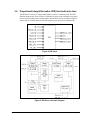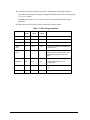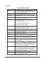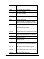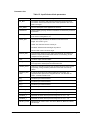
1
FOUNDATION Fieldbus ST 700 Pressure Transmitter User's Guide 34-ST-25-48 Revision 2.0 July 2014 Honeywell Process Solutions Copyrights, Notices and Trademarks © Copyright 2014 by Honeywell, Inc. Revision 2, July 2014 While this information is presented in good faith and believed to be accurate, Honeywell disclaims the implied warranties of merchantability and fitness for a particular purpose and makes no express warranties except as may be stated in its written agreement with and for its customers. In no event is Honeywell liable to anyone for any indirect, special or consequential damages. The information and specifications in this document are subject to change without notice. Honeywell, PlantScape, Experion PKS, and TotalPlant are registered trademarks of Honeywell International Inc. Other brand or product names are trademarks of their respective owners. Honeywell Process Solutions 1860 W. Rose Garden Lane Phoenix, AZ 85027 USA Page ii FOUNDATION Fieldbus ST 700 Pressure Transmitter User's Guide Revision 2.0 About This Document This guide provides the details of programming Honeywell ST 700 SmartLine Pressure Transmitters for applications involving FOUNDATION Fieldbus protocol. For installation, wiring, and maintenance information, refer to the ST 700 SmartLine Pressure Transmitter User Manual. The configuration of your transmitter depends on the mode of operation and the options selected for it with respect to operating controls, displays and mechanical installation. An ST 700 FF pressure transmitter can be digitally integrated with one of two systems: • Experion PKS, you need to supplement the information in this document with the data and procedures in the Experion PDF Collection. Release Information Document Name/ID ST 700 Pressure Transmitter User's Guide - 34-ST-25-48 First Release Release Number Publication Date 1.0 February 2013 2.0 July 2014 References The following list identifies all documents that may be sources of reference for material discussed in this publication. ST 700 SmartLine Pressure Transmitter User Manual, # 34-ST-25-44 SmartLine Pressure Transmitter Quick Start Installation Guide, # 34-ST-25-36 ST 800 & ST 700 SmartLine Pressure Transmitter w/ HART Comms Safety Manual, # 34-ST-25-37 ST 700 Series HART/DE Option User Manual, Document # 34-ST-25-47 Revision 2.0 FOUNDATION Fieldbus ST 700 Pressure Transmitter User's Guide Page iii Patent Notice The Honeywell ST 700 SmartLine Pressure Transmitter family is covered by one or more of the following U. S. Patents: 5,485,753; 5,811,690; 6,041,659; 6,055,633; 7,786,878; 8,073,098; and other patents pending. Support and Contact Information For Europe, Asia Pacific, North and South America contact details, see back page or refer to the appropriate Honeywell Solution Support web site: Honeywell Corporate www.honeywellprocess.com Honeywell Process Solutions www.honeywellprocess.com/pressue-transmitters/ Training Classes http://www.automationccollege.com Telephone and Email Contacts Area Organization United States and Canada Honeywell Inc. Global Email Support Honeywell Process Solutions Page iv Phone Number 1-800-343-0228 Customer Service 1-800-423-9883 Global Technical Support [email protected] FOUNDATION Fieldbus ST 700 Pressure Transmitter User's Guide Revision 2.0 Symbol Definitions The following table lists those symbols used in this document to denote certain conditions. Symbol Definition ATTENTION: Identifies information that requires special consideration. TIP: Identifies advice or hints for the user, often in terms of performing a task. REFERENCE -EXTERNAL: Identifies an additional source of information outside of the bookset. REFERENCE - INTERNAL: Identifies an additional source of information within the bookset. CAUTION Indicates a situation which, if not avoided, may result in equipment or work (data) on the system being damaged or lost, or may result in the inability to properly operate the process. CAUTION: Indicates a potentially hazardous situation which, if not avoided, may result in minor or moderate injury. It may also be used to alert against unsafe practices. CAUTION symbol on the equipment refers the user to the product manual for additional information. The symbol appears next to required information in the manual. WARNING: Indicates a potentially hazardous situation, which, if not avoided, could result in serious injury or death. WARNING symbol on the equipment refers the user to the product manual for additional information. The symbol appears next to required information in the manual. WARNING, Risk of electrical shock: Potential shock hazard where HAZARDOUS LIVE voltages greater than 30 Vrms, 42.4 Vpeak, or 60 VDC may be accessible. ESD HAZARD: Danger of an electro-static discharge to which equipment may be sensitive. Observe precautions for handling electrostatic sensitive devices. Protective Earth (PE) terminal: Provided for connection of the protective earth (green or green/yellow) supply system conductor. Functional earth terminal: Used for non-safety purposes such as noise immunity improvement. NOTE: This connection shall be bonded to Protective Earth at the source of supply in accordance with national local electrical code requirements. Revision 2.0 FOUNDATION Fieldbus ST 700 Pressure Transmitter User's Guide Page v Symbol Definition Earth Ground: Functional earth connection. NOTE: This connection shall be bonded to Protective Earth at the source of supply in accordance with national and local electrical code requirements. Chassis Ground: Identifies a connection to the chassis or frame of the equipment shall be bonded to Protective Earth at the source of supply in accordance with national and local electrical code requirements. Page vi FOUNDATION Fieldbus ST 700 Pressure Transmitter User's Guide Revision 2.0 Terms and Acronyms Term Definition Alarm The detection of a block leaving a particular state and when it returns back to that state. Analog Input (function block) One of the standard function blocks define by the Foundation Fieldbus AP Absolute Pressure Application A software program that interacts with blocks, events and objects. One application may interface with other applications or contain more than one application. AWG American Wire Gauge Block A logical software unit that makes up one named copy of a block and the associated parameters its block type specifies. It can be a resource block, transducer block or a function block. Configuration (of a system or device) A step in system design: selecting functional units, assigning their locations and identifiers, and defining their interconnections. Device A physical entity capable of performing one or more specific functions. Examples include transmitters, actuators, controllers, operator interfaces. Device Description Description of FBAPs within a device. Files that describe the software objects in a device, such as function blocks and parameters. The DD binary are created by passing DD source files through a standard tool called a tokenizer. Device Description Language A standardized programming language (similar to C) used to write device description source files. Device Tag The Physical Device Tag of the device as specified in the Foundation Fieldbus specifications. DP Differential Pressure EEPROM Electrically Erasable Programmable Read Only Memory EMI Electromagnetic Interference Event An instantaneous occurrence that is significant to scheduling block execution and to the operational (event) view of the application. Field Device A fieldbus-compatible device that contains and executes function blocks. Foundation Fieldbus Communications protocol for a digital, serial, two-way system which interconnects industrial field equipment such as sensors, actuators and controllers. FTA Field Termination Assembly Function Block An executable software object that performs a specific task, such as measurement or control, with inputs and outputs that connect to other function blocks in a standard way. Function Block Application Process The part of the device software that executes the blocks (function, transducer, or resource blocks). GP Gauge Pressure HP High Pressure (also, High Pressure side of a Differential Pressure Transmitter) Revision 2.0 FOUNDATION Fieldbus ST 700 Pressure Transmitter User's Guide Page vii Term Definition Hz Hertz inH2O Inches of Water LGP In-Line Gauge Pressure Link Active Scheduler A device which is responsible for keeping a link operational. The LAS executes the link schedule, circulates tokens, distributes time messages and probes for new devices. LP Low Pressure (also, Low Pressure side of a Differential Pressure Transmitter) LRL Lower Range Limit LRV Lower Range Value Macrocycle The least common multiple of all the loop times on a given link. mAdc Milliamperes Direct Current Manufacturer's Signal Processing A term used to describe signal processing in a device that is not defined by FF specifications. mmHg Millimeters of Mercury mV Millivolts Network Management A part of the software and configuration data in a Foundation Fieldbus device that handles the management of the network. Network Management Agent Part of the device software that operates on network management objects. Network Management Information Base A collection of objects and parameters comprising configuration, performance and fault-related information for the communication system of a device. Nm Newton. Meters NPT National Pipe Thread NVM Non-Volatile Memory Object Dictionary Definitions and descriptions of network visible objects of a device. There are various object dictionaries within a device. The dictionaries contain objects and their associated parameters which support the application in which they are contained. Objects Entities within the FBAP, such as blocks, alert objects, trend objects, parameters, display lists, etc. P Pressure Pa Measured static pressure in PV4 algorithm Parameters A value or variable which resides in block objects Pc Absolute critical pressure of the gas Pd Static pressure at downstream point Pdp Measured differential pressure in Pascals in PV4 algorithm Pf Absolute pressure of flowing gas PM Process Manger Page viii FOUNDATION Fieldbus ST 700 Pressure Transmitter User's Guide Revision 2.0 Term Definition Pr Reduced pressure Proportional Integral Derivative control A standard control algorithm. Also refers to a PID function block. PSI Pounds per Square Inch PSIA Pounds per Square Inch Absolute Pu Static pressure at upstream point PV Process Variable PWA Printed Wiring Assembly RFI Radio Frequency Interference RTD Resistance Temperature Detector Stack The software component that implement the Foundation Fieldbus communications protocol specifications, including FMS, FAS, DLL, SM and NM. Status A coded value that qualifies dynamic variables (parameters) in function blocks. This value is usually passed along with the value from block to block. Status is fully defined in the FF FBAP specifications. STIM Pressure Transmitter Interface Module STIMV IOP Pressure Transmitter Interface Multivariable Input / Output Processor System Management Provides services that coordinate the operation of various devices in a distributed fieldbus system. System Management Agent Part of the device software that operates on system management objects. System Management Information Base A collection of objects and parameters comprising configuration and operational information used for control of system management operations. TAC Technical Assistance Center Trim Point A selected reference point at which a measurement is calibrated. URL Upper Range Limit URV Upper Range Value US Universal Station Vac Volts Alternating Current Vdc Volts Direct Current Virtual Communication Reference A defined communication endpoint. Fieldbus communications can primarily only take place along an active communications "path" that consists of two VCR endpoints. Virtual Field Device A logical grouping of "user layer" functions. Function blocks are grouped into a VFD, and system and network management are grouped into a VFD. For example, to establish communications between a transducer block and a function block, a VCR must be defined at the transducer block and a VCR must be defined at the function block. Revision 2.0 FOUNDATION Fieldbus ST 700 Pressure Transmitter User's Guide Page ix Contents COPYRIGHTS, NOTICES AND TRADEMARKS.................................... II 1. INTRODUCTION ............................................................................ 1 1.1 About the ST 700 FF Pressure Transmitter...................................................1 1.2 ST 700 major assembly and electronic housing components ....................2 1.3 Features of the transmitter .............................................................................3 2. GETTING STARTED...................................................................... 5 2.1 Verifying the installation .................................................................................5 Verifying transmitter installation tasks ................................................................................... 5 2.2 Verifying communication with the transmitter .............................................6 Identify the transmitter ........................................................................................................... 6 2.3 Establishing communication with host systems .........................................7 Device Description (DD) ........................................................................................................ 7 Enhanced Device Description (EDD) .................................................................................... 7 Device Type Manager (DTM) ................................................................................................ 7 3. ST 700 FF PRESSURE TRANSMITTER CONFIGURATION ........ 8 3.1 Importing the ST 700 FF Device Description (DD) files ...............................8 Importing the DD to Experion PKS ........................................................................................ 8 3.2 Configuring the function block application process .................................12 About the Function Block Application Process (FBAP) ....................................................... 12 Block Alarms ....................................................................................................................... 12 Process Alarms ................................................................................................................... 14 3.3 Resource block ..............................................................................................15 Configuring the Resource block .......................................................................................... 15 RESTART ........................................................................................................................... 15 Execution ............................................................................................................................ 16 CYCLE TYPE ...................................................................................................................... 16 MEMORY ............................................................................................................................ 16 MAX NOTIFY ...................................................................................................................... 16 FEATURES ......................................................................................................................... 16 Reports ................................................................................................................................ 16 SOFT W LOCK and HARD W LOCK .................................................................................. 17 Field Diagnostics ................................................................................................................. 18 Parameter List ..................................................................................................................... 21 3.4 Pressure Transducer block ..........................................................................25 Execution ............................................................................................................................ 25 Level Calculation ................................................................................................................. 27 Calibration ........................................................................................................................... 28 Sensors ............................................................................................................................... 29 Parameter List ..................................................................................................................... 30 Page x FOUNDATION Fieldbus ST 700 Pressure Transmitter User's Guide Revision 2.0 3.5 Diagnostic Transducer block .......................................................................33 Execution ............................................................................................................................ 33 Sensor ................................................................................................................................. 33 Sensor General Diagnostics ................................................................................................ 34 Device Diagnostics .............................................................................................................. 34 Time in Service.................................................................................................................... 35 Power Cycle Track .............................................................................................................. 35 Parameter List ..................................................................................................................... 36 3.6 LCD Transducer block ..................................................................................38 Execution ............................................................................................................................ 38 Parameters List ................................................................................................................... 41 3.7 Flow Transducer block..................................................................................43 Execution ............................................................................................................................ 43 Configuration ....................................................................................................................... 44 Parameter List ..................................................................................................................... 44 Attributes ............................................................................................................................. 45 3.8 Analog Input block ........................................................................................46 Execution ............................................................................................................................ 46 Parameters List ................................................................................................................... 49 Attributes ............................................................................................................................. 52 3.9 Proportional Integral Derivative (PID) block with auto tune......................53 Execution ............................................................................................................................ 54 Auto tuning .......................................................................................................................... 57 Auto tuning procedure ......................................................................................................... 57 Parameter list ...................................................................................................................... 58 Attributes ............................................................................................................................. 62 3.10 Input Selector block ...................................................................................63 Execution ............................................................................................................................ 63 Parameters List ................................................................................................................... 65 Attributes ............................................................................................................................. 67 3.11 Integrator block ..........................................................................................68 Execution ............................................................................................................................ 68 Parameters List ................................................................................................................... 74 Attributes ............................................................................................................................. 76 3.12 Arithmetic block .........................................................................................77 Execution ............................................................................................................................ 77 Attributes ............................................................................................................................. 82 3.13 Signal Characterizer block ........................................................................83 Execution ............................................................................................................................ 83 Parameter list ...................................................................................................................... 85 Attributes ............................................................................................................................. 86 3.14 4. Configuring the transmitter using Field Device Manager (FDM) system86 ST 700 FF PRESSURE TRANSMITTER OPERATION ............... 87 4.1 Operational considerations ..........................................................................87 LAS Capability ..................................................................................................................... 87 Special Non-volatile parameters and NVM Wear-out .......................................................... 87 Mode Restricted Writes to Parameters ................................................................................ 87 4.2 Configuration of the transmitter using Handheld (HH) ..............................88 4.3 Performing block instantiation .....................................................................89 About block instantiation ..................................................................................................... 89 Block instantiation using Experion PKS ............................................................................... 89 Revision 2.0 FOUNDATION Fieldbus ST 700 Pressure Transmitter User's Guide Page xi 5. ST 700 FF PRESSURE TRANSMITTER MAINTENANCE .......... 91 5.1 Replacing the Local Display and Electronic Assembly .............................91 5.2 Downloading the firmware ............................................................................91 About firmware download feature ........................................................................................ 91 Class 3 ................................................................................................................................ 91 Recommendations .............................................................................................................. 92 Downloading the File ........................................................................................................... 92 6. ST 700 FF PRESSURE TRANSMITTER TROUBLESHOOTING 94 6.1 Troubleshooting overview ............................................................................94 Device status and faults ...................................................................................................... 94 6.2 Troubleshooting the transmitter ..................................................................95 Device not visible on the network ........................................................................................ 95 Incorrect or non-compatible tools ........................................................................................ 96 6.3 Troubleshooting blocks ................................................................................97 Non-functioning blocks ........................................................................................................ 97 Troubleshooting block configuration errors ......................................................................... 97 Troubleshooting the Resource block ................................................................................... 97 Troubleshooting the Pressure Transducer block ................................................................. 98 Troubleshooting the Diagnostics Transducer block ............................................................. 99 Troubleshooting the Flow Transducer block ...................................................................... 100 Troubleshooting the LCD Transducer block ...................................................................... 101 Troubleshooting the Analog Input (AI) block ..................................................................... 102 Troubleshooting the Proportional Integral Derivative (PID) block ...................................... 103 Troubleshooting the Input Selector block .......................................................................... 104 Troubleshooting the Integrator block ................................................................................. 105 Troubleshooting the Arithmetic block ................................................................................ 106 Troubleshooting the Signal Characterizer block ................................................................ 107 Resolving the block configuration errors ........................................................................... 108 6.4 Device Diagnostics ......................................................................................110 ST 700 FF pressure transmitter memory........................................................................... 110 Performing diagnostics in the background ........................................................................ 110 BLOCK_ERR parameter ................................................................................................... 110 Background Diagnostics Execution, BLOCK_TEST parameter ........................................ 111 Transmitter Diagnostics ..................................................................................................... 111 Function Block Faults ........................................................................................................ 112 6.5 Understanding simulation mode ................................................................116 About simulation mode jumper .......................................................................................... 116 Setting simulation jumper .................................................................................................. 116 Enabling simulation mode ................................................................................................. 117 Simulation mode truth table ............................................................................................... 117 Setting Al block mode........................................................................................................ 117 6.6 Understanding write protection .................................................................118 SALES AND SERVICE ...................................................................... 119 Page xii FOUNDATION Fieldbus ST 700 Pressure Transmitter User's Guide Revision 2.0 Tables Table 1: Transmitter installation verification tasks .............................................5 Table 2: Transmitter parameters .......................................................................6 Table 3: Bit mapping of the BLOCK_ERR .......................................................12 Table 4: Priority for Alarms ..............................................................................14 Table 5: Diagnostic Definitions ........................................................................18 Table 6: Resource block parameters...............................................................21 Table 7: Pressure Transducer block parameters .............................................30 Table 8: Diagnostic Transducer block parameters ..........................................36 Table 9 LCD parameters .................................................................................39 Table 10: LCD Transducer block parameters ..................................................41 Table 11: Flow Transducer block parameters .................................................44 Table 12: Analog Input block parameters ........................................................49 Table 13: PID Tuning parameters ...................................................................56 Table 14: PID block parameters ......................................................................58 Table 15: Input Selector block parameters ......................................................65 Table 16: Integrator block parameters.............................................................74 Table 17: Arithmetic block parameters ............................................................80 Table 18: Signal Characterizer block parameters ............................................85 Table 19: Resource block ...............................................................................97 Table 20: Pressure Transducer block ..............................................................98 Table 21: Diagnostics Transducer block .........................................................99 Table 22: Flow Transducer block ..................................................................100 Table 23: LCD Transducer block ...................................................................101 Table 24: Analog Input block .........................................................................102 Table 25: PID block .......................................................................................103 Table 26: Input Selector block .......................................................................104 Table 27: Integrator block .............................................................................105 Table 28: Arithmetic block .............................................................................106 Table 29: Signal Characterizer block.............................................................107 Table 30: Resolving block configuration errors ..............................................108 Table 31: Diagnostics....................................................................................110 Table 32: Identifying Critical and Non-critical Function block faults ............... 112 Table 33: Summary of Function blocks Non-critical Faults ............................114 Table 34: Summary of Function blocks Critical Faults ...................................115 Table 35: Setting the Simulation Jumper .......................................................117 Table 36: Simulation Mode Truth Table ........................................................117 Table 37: Write lock ......................................................................................118 Revision 2.0 FOUNDATION Fieldbus ST 700 Pressure Transmitter User's Guide Page xiii Figures Figure 1: ST 700 Major assemblies .................................................................. 2 Figure 2: Electronic Housing components ........................................................ 2 Figure 3: Pressure Transducer Block ............................................................. 25 Figure 4: LCD Transducer Block .................................................................... 38 Figure 5: Flow Transducer Block .................................................................... 43 Figure 6: Analog Input Block .......................................................................... 46 Figure 7: Analog Input Block Schematic Diagram ........................................... 47 Figure 8: PID block ......................................................................................... 53 Figure 9: PID block schematic diagram .......................................................... 53 Figure 10: Input Selector block ....................................................................... 63 Figure 11: Input Selector schematic diagram.................................................. 64 Figure 12: Integrator Block ............................................................................. 68 Figure 13: Two Rate Inputs ............................................................................ 69 Figure 14: Arithmetic block ............................................................................. 77 Figure 15: Arithmetic schematic diagram ........................................................ 78 Figure 16: Signal Characterizer Block ............................................................ 83 Figure 17: Signal characterizer curve ............................................................. 84 Figure 18: Connecting the transmitter to the handheld ................................... 88 Figure 19: Simulation Jumper Location on Transducer Board ...................... 116 Page xiv FOUNDATION Fieldbus ST 700 Pressure Transmitter User's Guide Revision 2.0 1. Introduction 1.1 About the ST 700 FF Pressure Transmitter The newly designed Honeywell ST 700 is a smart pressure transmitter that has a wide range of additional features along with supporting the FOUNDATIONTM Fieldbus (FF) communication protocol. The ST 700 pressure transmitter with FF protocol provides a FOUNDATIONTM Fieldbus interface to operate in a compatible distributed Fieldbus system. The transmitter includes FOUNDATIONTM Fieldbus electronics for operating in a 31.25 Kbit/s Fieldbus network and can interoperate with any FOUNDATIONTM Fieldbus registered device. The STD700 is a high performance pressure transmitter featuring Piezo-resistive sensor technology. By combining differential pressure sensing with on-chip static and temperature compensation, the STD700 offers high accuracy and stability over a wide range of application pressures and temperatures. The STG700 and STA700 are high performance pressure transmitters featuring Piezo-resistive sensor technology combining pressure sensing with on-chip temperature compensation capabilities providing high accuracy, stability and performance over a wide range of application pressures and temperatures. The SmartLine family is also fully tested and compliant with Experion ® PKS providing the highest level of compatibility assurance and integration capabilities. The ST 700 easily meets the most demanding application needs for pressure measurement applications. This transmitter is used in the process automation industry for sensing and transmitting pressure over intelligent communication networks. The transmitter comes in a variety of models for measurement applications involving one of these basic types of pressure: Revision 2.0 • Differential Pressure (DP) • Gauge Pressure (GP) • Absolute Pressure (AP) FOUNDATION Fieldbus ST 700 Pressure Transmitter User's Guide Page 1 1.2 ST 700 major assembly and electronic housing components The following illustrations depict the major assembly and electronic housing components. Figure 1: ST 700 Major assemblies Figure 2: Electronic Housing components Page 2 FOUNDATION Fieldbus ST 700 Pressure Transmitter User's Guide Revision 2.0 1.3 Features of the transmitter The transmitter is a configurable intelligent field device that acts as a pressure sensor, and is capable of performing control algorithms on process variables. The core functionalities of the field device include: • Process Variable (PV) measurement • Function Block Application Process (FBAP) • Device diagnostics The ST 700 features standard fieldbus function blocks with manufacturer-specific additions for enhanced operation. The transmitter can function as a Link Active Scheduler (LAS) in a Fieldbus network. It supports the following features: • • • • • Link-master capability Supports the following standard function blocks apart from the Resource and Transducer blocks. − Analog Input block − Input Selector block − Integrator block − Signal Characterizer block − PID with auto tune block − Arithmetic block Function block instantiation is supported by the following blocks − Analog Input block − Input Selector block − Signal Characterizer block Supports the following Transducer blocks − Pressure Transducer block − LCD Transducer block − Diagnostic Transducer block − Flow Transducer block Supports class 3 type firmware download through commercial hosts. DD and EDDL Features The ST 700 supports DD and EDD file formats, and the data is displayed using the EDDL features in the form of menus, graphs, charts, and pictures. Revision 2.0 FOUNDATION Fieldbus ST 700 Pressure Transmitter User's Guide Page 3 Page 4 FOUNDATION Fieldbus ST 700 Pressure Transmitter User's Guide Revision 2.0 2. Getting started 2.1 Verifying the installation Verifying transmitter installation tasks After the transmitter is installed and powered up, you can verify communication between the transmitter and the field devices on the network. Table 1 outlines the steps for identifying and checking the transmitter on a Fieldbus network. Table 1: Transmitter installation verification tasks Task Description Verify device location Check that the device is installed in the correct physical location. Verify device ID Match the device ID with the physical location. Comment The device serial number is the PROM ID which is stamped on the transmitter housing nameplate. Verify connection with host computer to device On the operator interface, check and make sure communications are established with the device on the Fieldbus network. Verify or assign Device Tag and address Check that the Device Tag and node address are set. If not, assign the Device Tag and the correct node address. The Device Tag and address can be set and viewed using the Fieldbus device configurator application. Use a Device Tag name (up to 16 characters) that does not contain spaces. Revision 2.0 Configure device Using a Fieldbus configuration program, create a function block application as part of the device configuration and process control strategy. Verify device operation Bring the network online, verify operation, tune loops, and so on. FOUNDATION Fieldbus ST 700 Pressure Transmitter User's Guide Page 5 2.2 Verifying communication with the transmitter On the operator interface, establish communication with the device on the Fieldbus network. If the device is not visible on the network, verify that the device has been installed properly. Identify the transmitter Verify the Device ID of the transmitter by checking the device parameters. The parameters contain the following information: • Transmitter type (pressure transmitter, temperature transmitter, and flow transmitter) • Device Tag (tag description of the transmitter) • Sensor serial number • Firmware revision level (revision level of the firmware elements) Check the transmitter parameters listed in Table 2 and note down the values to identify the transmitter. ATTENTION It is recommended to verify the correct version of the Device Description file is present on the host computer. (Refer to the document on the diskette shipped with the transmitter.) This helps in getting the correct parameter names and its corresponding descriptions, while viewing the device parameters. Table 2: Transmitter parameters Parameter Resource block To verify DEV_TYPE That the transmitter is of the proper device type. For all the ST 700 type pressure transmitters, the value is 0003. Device Tag The Device Tag is correct. (Physical device tag name of the transmitter) Device Tag name __________________ ATTENTION The Device Tag name can be set and viewed using the Fieldbus device configurator application. Use a device tag name (up to sixteent characters) that does not contain spaces. Transducer Block Sensor serial # ________________ SENSOR_SN The SENSOR_SN value, when viewed as a hexadecimal number, is the same number as the first sixteen digits of the PROM ID stamped on the transmitter housing nameplate. ATTENTION Note that the eight digit serial number in the SENSOR_SN parameter does not display the last two digits of the PROM ID stamped on the nameplate of the transmitter housing. The Device ID contains the full 10-digit PROM ID. Page 6 FOUNDATION Fieldbus ST 700 Pressure Transmitter User's Guide Revision 2.0 2.3 Establishing communication with host systems The transmitter establishes communication with the host systems using DD or DTM. Device Description (DD) DD is a binary file that provides the definition for parameters in the FBAP of the transmitter. For example, DD refers to the function blocks that a transmitter contains, and the corresponding parameters in the blocks that are critical to the interoperability of Fieldbus devices. They define the data required to establish communications between different Fieldbus devices from multiple vendors with control system hosts. The DD provides an extended description of each object in the Virtual Field Device (VFD). The Fieldbus Foundation provides the DD for all standard function blocks and transducer blocks on a CD-ROM. The Fieldbus Foundation also provides this information on its website, www.fieldbus.org. Enhanced Device Description (EDD) There are two types of EDDs are available, namely .ff5/.sy5 and .ffo/sym. The.ffo/.sym binary files are generated for the legacy hosts to load the device DD that is generated using latest tokenizer. Few constructs like Images that are supported in .ff5/.sy5 binaries, are not supported in .ffo/.sym binary files. Device Type Manager (DTM) DTM is similar to a device driver that enables usage of devices in all the asset management and device configuration software like FDM, with the help of the FDT-DTM technology. The DTM has the following primary functions: • • Provides a graphic user interface for device configuration. Provides device configuration, calibration, and management features for the particular device. DTM provides functions for accessing device parameters, configuring and operating the devices, calibrating, and diagnosing problems. Revision 2.0 FOUNDATION Fieldbus ST 700 Pressure Transmitter User's Guide Page 7 3. ST 700 FF Pressure Transmitter Configuration 3.1 Importing the ST 700 FF Device Description (DD) files Importing the DD to Experion PKS ATTENTION Experion release compatibility Experion Release DD Compatibility 410 Yes 400.2 + CP3 Yes 311.3 Yes The steps in the following procedure are specific to Experion only. Step 1 Action From the Control builder main screen, click Fieldbus Device Description Import . OR Select File > New > Type >Fieldbus Device 2 2 You can Import the DD using one of the following steps: • Choose Browse • Select the required folder, and click OK. • Select the DD from the Device List, and click OK. to locate the folder where you have stored the DD file. The following dialog box appears, Click OK 3 Page 8 Type the Device Type Name, and then click Save As. FOUNDATION Fieldbus ST 700 Pressure Transmitter User's Guide Revision 2.0 Step 4 Action The following dialog box appears, Click OK. 5 The following dialog box appears, Click OK. ATTENTION The device type – ST700FF_R1_0102 is used as an example. 6 The device is created in the Library-Containment window under the folder named Honeywell. 7 From the Library-Containment window, drag and drop the device into the corresponding FF link on the Project-Assignment window. 8 You are prompted to name the new function block. If you want to change the name in the destination column, type the new name or if you want to use the default name, click Finish. The device is added on the FF link on the Project-Assignment window. 9 Revision 2.0 Right-click the new device and then click Load. FOUNDATION Fieldbus ST 700 Pressure Transmitter User's Guide Page 9 Step 10 Action The following WARNING appears. Click Continue. 11 The following dialog box appears, Select the Automatically change ALL control elements to the state selected in “Post Load State” after load is completed checkbox and click OK. 11 On the Monitoring-Assignment window, you can notice that device on the Project-Assignment window has been loaded to the corresponding FF link. 12 Right-click the device, and then click Activate >> Selected Item(s) and Content(s). The device is commissioned. ATTENTION Note that after importing the DD, you have to create control strategies. Page 10 FOUNDATION Fieldbus ST 700 Pressure Transmitter User's Guide Revision 2.0 Control strategy A control strategy is an organized approach to define a specific process using detailed information to: • create control modules in an associated controlled environment • configure function blocks to enable control applications, and • runs in a control software infrastructure To build a control strategy, a Control Module (CM) must be created where function blocks are inserted and connected with other function blocks. Creating control strategy For information on creating control strategy, refer to the corresponding DCS document. ATTENTION When control strategy is loaded by deselecting the partial download option in the Experion, parameter check errors will appear. Ignore the errors and continue the loading of control strategy. Revision 2.0 FOUNDATION Fieldbus ST 700 Pressure Transmitter User's Guide Page 11 3.2 Configuring the function block application process About the Function Block Application Process (FBAP) The transmitter has one resource block, four transducer blocks, and six function blocks respectively. The DD-View feature supports all the 11 permanent blocks. The FBAP provides the block related information in a much more organized way. The FBAP defines blocks to represent different types of application functions. In addition, the blocks have a static revision parameter. The revision level of the static data is associated with the function block. To support tracking changes in static parameter attributes, the associated block’s static revision parameter is incremented each time a static parameter attribute value is changed. In addition, the associated block’s static revision parameter is incremented, if a static parameter attribute is written but the value is not changed. The FBAP supports two types of alarms: block alarms and process alarms. A block alarm is generated whenever the BLOCK_ERR has an error bit set. The types of block error for the AI block are shown in Table 3. The following alarms are supported by each function block: Block Alarms Table 3: Bit mapping of the BLOCK_ERR Block_ERR Bit 0 Block Alarms Other Description Least significant bit (LSB). NOTE: It is not applicable to the transmitter. 1 Block Configuration error A feature in FEATURES_SEL is set that is not supported by features or an execution cycle in CYCLE_SEL is set that is not supported by CYCLE_TYPE. 2 Link Configuration error If the link is not configured properly. 3 Simulation Active The jumper or switch that enables simulation within the resource is ON. The individual I/O function blocks disable the simulation. 4 Local Override The block output is being set to track the value of the track input parameter. NOTE: It is not applicable to the transmitter. 5 Device Fault State Set If the Device Fault State condition is True. NOTE: It is not applicable to the transmitter. Page 12 FOUNDATION Fieldbus ST 700 Pressure Transmitter User's Guide Revision 2.0 Block_ERR Bit 6 Block Alarms Device Needs Maintenance Soon Description A diagnostic algorithm has found a warning condition. The NV memory is approaching the maximum number of reliable writes. NOTE: It is not applicable to the transmitter. 7 Input Failure When a sensor failure (open thermocouple) or sensor conversion not accurate. 8 Output Failure Output Failure detected by this block/back calculation input has a status of Bad or Device Failure. NOTE: It is not applicable to the transmitter. 9 Memory Failure A diagnostic algorithm has found a failure in memory (includes all types) and the device is still able to communicate that condition. 10 Lost Static data If the object’s static data is Bad, then the object’s database is set to its default values. 11 Lost NV data The NV and static parameters are saved periodically. This alarm occurs, if new data was supposed to be saved to NV at the next NV write cycle, but prevented the write due to power failure. 12 Readback Check failed This indicates the readback of the actual continuous valve or other actuator position in transducer units has failed. 13 Device needs maintenance now A diagnostic algorithm has found an invalid condition, but the device is still able to operate and communicate. The NV memory has reached the maximum number of reliable writes. NOTE: It is not applicable to the transmitter. 14 Power-up The resource is performing its first normal execution, after power was applied to the device. It is not an error but generates an alarm that says that normal operation was interrupted and is now being restored. NOTE: It is not applicable to the transmitter. 15 Revision 2.0 Out-of-Service The actual mode is OOS. No control function blocks are being processed. FOUNDATION Fieldbus ST 700 Pressure Transmitter User's Guide Page 13 Process Alarms A set of alarms that indicates a process value has exceeded a certain threshold. Process Alarm detection is based on the OUT value. The alarm limits can be configured for the following standard alarms: • High (HI_LIM) • High High (HI_HI_LIM) • Deviation High Limit (DEV_HI_LIM) • Deviation Low Limit (DEV_LO_LIM) • Low (LO_LIM) • Low Low (LO_LO_LIM) When the value OUT oscillates, ALARM_HYS is used to avoid alarm triggering. The priority of each alarm is set by the following parameters: • HI_PRI • HI_HI_PRI • DV_HI_PRI • DV_LO_PRI • LO_PRI • LO_LO_PRI The following is the order of priority for alarms. Table 4: Priority for Alarms Priority Description 0 To disable the triggered alarm, the priority of an alarm condition is changed to 0. 1 Alarm condition with a priority 1 is reported to the system, but not reported as an event and alarm 2 Alarm condition with priority of 2 is reported to the system and event, but not reported as an alarm. 3-7 Alarm conditions of priority 3 to 7 are reported as advisory alarms. 8-15 Alarm conditions of priority 8 to 15 are reported as critical alarms. ATTENTION Process alarms are not supported by all blocks. Page 14 FOUNDATION Fieldbus ST 700 Pressure Transmitter User's Guide Revision 2.0 3.3 Resource block The Resource block is used to describe characteristics of the Fieldbus device such as the device name, manufacturer, and serial number. The block does not contain any input or output parameters. The block contains data that is specific to the hardware associated with the resource. The resource block monitors and controls the general operation of the device hardware. For example, if the resource block is in out of service mode, it affects all the other blocks. The ITK_VER parameter is used to identify the version of the Interoperability Tester. The transmitter’s Revision and Versions, Model Number, and Material of Construction of the meterbody can be obtained by executing the methods available in the resource block. The block modes are used to control major states of the resource: • The OOS mode stops all function block execution. • The Actual mode of the function blocks changes to OOS but the target mode does not change. • The AUTO mode allows normal operation of the resource. Configuring the Resource block The Resource block supports scalar input only as HARD_TYPES. This parameter is a read-only bit string that indicates the types of hardware that are available for this resource. The RS_STATE parameter contains the operational state of the Function Block Application for the data containing that resource block. RESTART The RESTART parameter allows degrees of initialization of the resource. Restart Revision 2.0 Operation Run (1) The passive state of the parameter. Restart resource (2) Discards unnecessary alarms, and also discards the resource dynamic values. Restart with defaults (3) Resets all configurable function block application objects to their initial value, which is their value before any configuration is done. Restart processor (4) Provides a way to press the reset button on the processor associated with the resource. FOUNDATION Fieldbus ST 700 Pressure Transmitter User's Guide Page 15 Execution CYCLE TYPE The parameter CYCLE_TYPE is a bit string that defines the types of cycles that are available for the resource and supports scheduled and block execution. CYCLE_SEL allows the person doing the configuration to indicate that one or more of these execution types can be used by the device. MIN_CYCLE_T is the minimum time to execute a cycle; the minimum cycle time supported is 100 ms. MEMORY MEMORY_SIZE is the size of the resource for configuration of function blocks; it is represented in kilobytes. SHED_RCAS and SHED_ROUT set the time limit for loss of communication from a remote device. These constants are used by each function block and are configurable values. MAX NOTIFY The MAX_NOTIFY parameter value is the maximum number of alert reports that this resource can send without getting a confirmation, and to control alert flooding, adjust the LIM_NOTIFY parameter to a lower value. If LIM_NOTIFY is set to zero, no alerts are reported. The CONFIRM_TIME parameter is the time for the resource to wait for confirmation of receipt of a report before trying again. FEATURES The bit strings FEATURES and FEATURE_SEL determine optional behaviour of the resource. FEATURES bit string defines the available features; it is read-only. FEATURE_SEL is used to turn on an available feature by configuration. Reports If the Reports option is set in the Features bit strings, the transmitter actively sends alerts to host/master. If it is not set, the host/master must poll for alerts. Page 16 FOUNDATION Fieldbus ST 700 Pressure Transmitter User's Guide Revision 2.0 SOFT W LOCK and HARD W LOCK There are two types of write locks: Hardware write lock and Software write lock. The software write lock is used to lock the device. The software write lock does not need a jumper. A hardware write lock is provided with a jumper in the device to perform the write lock operation. If the WRITE_LOCK parameter is set, it prevents any external change to the static or nonvolatile database in the Function Block Application of the resource. Block connections and calculation results proceeds normally but the configuration is locked. A hard write lock is provided by a jumper in the device as indicated in the FEATURES bit string. Clearing WRITE_LOCK generates the discrete alert WRITE_ALM at the WRITE_PRI priority. If the soft write lock bit is not set as True in the features bit strings, the writing to the parameter WRITE_LOCK is rejected by the device. For devices that support hard write lock and have the associated FEATURE_SEL attribute enabled, the parameter WRITE_LOCK is only an indicator of the state of write-lock. The writing to WRITE_LOCK is rejected by the device. Software write lock To activate write lock, the soft write lock supported bit in FEATURE_SEL must be set, and then set the WRITE_LOCK to locked. To deactivate write lock, set the WRITE_LOCK to unlocked. Hardware write lock To activate write lock, the hard write lock supported bit in FEATURE_SEL must be set, and additionally the write lock jumper must be in the correct position as determined by the manufacturer. When this is detected by the device, WRITE_LOCK is set to locked. If hard write lock is enabled in FEATURE_SEL, the configured value of soft write lock has no impact on device operation. To deactivate write lock, the jumper must be changed as FEATURE_SEL is not writeable during write lock. Once the device detects the change in jumper position, the write-lock is disabled and WRITE_LOCK is set to 1. Install Date When the device is connected to the master/host, the time at which the device is powered up is taken as the install date. It is a read-only parameter. Revision 2.0 FOUNDATION Fieldbus ST 700 Pressure Transmitter User's Guide Page 17 Field Diagnostics The Resource block acts as a coordinator for alarms. There are four alarm parameters: Fail alarm, Offspec alarm, Maintenance alarm, and Check alarm. It contains information of device errors that are detected by the transmitter. Based on the error detected, the device provides the recommended actions; it is a read only parameter. It displays the recommended action text for the reported alarms. Table 5: Diagnostic Definitions Name Description Maintenance Although the output signal is valid, the wear reserve is nearly exhausted or a function is soon restricted due to operational conditions. For example, buildup of deposits. Off Specification Indicates if the device is operating outside its specified range or internal diagnostics indicate deviations from measured or set values due to internal problems in the device or process characteristics. Check Function Output signal temporarily invalid due to on-going work on the device. Failed Output signal invalid due to malfunction in the field device or its peripherals. FAILED_ALARMS Failed alarms indicate a failure within a device that makes the device or some part of the device non-operational. This implies that the device needs repair and must be fixed immediately. • FAILED_MAPPED parameter contains a list of failures in the device which makes the device non-operational that causes an alarm. There are four parameters mapped by default with FAILED_MAPPED: Meterbody fault, Communication board fault, and No communication with meterbody. • FAILED_MASK parameter masks any of the failed conditions listed in FAILED_MAPPED. A bit on means that the condition is masked out from alarming and is not reported. • FAILED_PRI parameter designates the alarming priority of FAILED_ALM. The default is 0. • • Page 18 FAILED_ACTIVE parameter displays the alarms that are active. FAILED_ALM parameter indicates a failure within a device which makes the device non-operational. FOUNDATION Fieldbus ST 700 Pressure Transmitter User's Guide Revision 2.0 MAINT_ALARMS A maintenance alarm indicates either the device or some part of the device needs maintenance. If the condition is ignored, the device eventually fails. • MAINT_MAPPED parameter contains a list of conditions indicating either the device or some part of the device needs maintenance soon. If the condition is ignored, the device eventually fails. There are six parameters mapped by default with MAINT_MAPPED: meterbody overload or fault, Communication board over temperature, no factory calibration, low supply voltage, high supply voltage, and unreliable sensor communication. • MAINT_MASK parameter masks any of the failed conditions listed in MAINT_MAPPED. A bit on means that the condition is masked out from alarming and is not reported. • MAINT_PRI designates the alarming priority of the MAINT_ALM. The default is 0. • MAINT_ACTIVE parameter displays the alarms that are active. • MAINT_ALM parameter indicates that the device needs maintenance. If the condition is ignored, the device fails. CHECK_ALARMS It indicates that the output signal is temporarily invalid due to on-going work on the device. • CHECK_MAPPED parameter contains a list of informative conditions that do not have a direct impact on the device's primary functions. • CHECK_MASK parameter masks any of the failed conditions listed in CHECK_MAPPED. A bit on means the condition is masked out from alarming and is not reported. • CHECK_PRI parameter designates the alarming priority of the CHECK_ALM. The default is 0. • • Revision 2.0 CHECK_ACTIVE parameter displays the check alarms that are active. CHECK_ALM parameter indicates check alarms. These conditions do not have a direct impact on the process or device integrity. FOUNDATION Fieldbus ST 700 Pressure Transmitter User's Guide Page 19 OFFSPEC_ALARMS Indicates if the device is operating outside its specified range or internal diagnostics indicates deviations from measured or set values due to internal problems in the device or process characteristics. • OFFSPEC_MAPPED parameter contains a list of informative conditions that do not have a direct impact on the device's primary functions. • OFFSPEC_MASK parameter masks any of the failed conditions listed in OFFSPEC_MAPPED. A bit on means the condition is masked out from alarming and is not reported. • OFFSPEC_PRI parameter designates the alarming priority of the OFFSPEC_ALM. The default is 0. • • OFFSPEC_ACTIVE parameter displays the offspec alarms that are active. OFFSPEC_ALM parameter indicates offspec alarms. These conditions do not have a direct impact on the process or device integrity. RECOMMENDED_ACTION The RECOMMENDED_ACTION parameter displays a text string that give a recommended course of action to take based on which type and which specific event of the alarms is active. FD_SIMULATE When simulation is enabled the Field Diagnostics conditions are taken from the Diagnostic Simulate Value, or else the conditions are taken from Diagnostic Value, and the RECOMMENDED_ACTION parameter displays the text as ‘Simulation Active’. ATTENTION Note that FD_SIMULATE can be enabled only if the simulation jumper is enabled in the device. For more information refer section 6.5 Page 20 FOUNDATION Fieldbus ST 700 Pressure Transmitter User's Guide Revision 2.0 MAINTENANCE_MODE It indicates if the device is available for maintenance. When the resource block is in AUTO mode, MAINTENANCE_MODE parameter displays the text as 'Chk with Oper', that is the device is in process and is not available for maintenance. When the resource block is in OOS mode, MAINTENANCE_MODE parameter displays the text as ‘Avail for Maint' that is the device is out of process and is available for maintenance. 'Chk with Oper'- Check with operator to determine availability. ‘Avail for Maint'- The device is available for maintenance. Parameter List Table 6: Resource block parameters Parameter Description ST_REV The revision level of the static data associated with the function block. TAG_DESC The user description of the application of the block. STRATEGY Used to identify grouping of blocks. ALERT_KEY The identification number of the plant unit. MODE_BLK The actual, target, permitted, and normal modes of the block. BLOCK_ERR Reflects the error status associated with the hardware or software components associated with a block. It is a bit string, so that multiple errors may be shown. RS_STATE Indicates the State of the function block application state machine. TEST_RW Read/write test parameter is used only for conformance testing. DD_RESOURCE String identifying the tag of the resource, which contains the Device Description for the resource. MANUFAC_ID Manufacturer identification number is used by an interface device to locate the DD file for the resource. DEV_TYPE Manufacturer model number associated with the resource. It is used by interface devices to locate the DD file for the resource. DEV_REV Manufacturer revision number associated with the resource. It is used by an interface device to locate the DD file for the resource. DD_REV Revision of the DD associated with the resource. It is used by the interface device to locate the DD file for the resource. GRANT_DENY Options for controlling access of host computer and local control panels to operating, tuning and alarm parameters of the block. HARD_TYPES The types of hardware available as channel numbers. The supported hardware type is SCALAR_INPUT. RESTART Allows a manual restart to be initiated. FEATURES Used to show supported resource block options. The supported features are: REPORT, SOFT_WRITE_LOCK, HARD_WRITE_LOCK, and MULTI_BIT_ALARM. Revision 2.0 FOUNDATION Fieldbus ST 700 Pressure Transmitter User's Guide Page 21 Parameter Description FEATURE_SEL Used to select resource block FEATURE_SEL options CYCLE_TYPE Identifies the block execution methods available for this resource. The supported cycle types are: SCHEDULED, and COMPLETION_OF_BLOCK_EXECUTION. CYCLE_SEL Used to select the block execution method for this resource. MIN_CYCLE_T Time duration of the shortest cycle interval of which the resource is capable. MEMORY_SIZE Available configuration memory in the empty resource. It must be checked before starting a download. NV_CYCLE_T Minimum time interval specified by the manufacturer for writing copies of NV parameters to non-volatile memory. Zero implies it is never automatically copied. At the end of NV_CYCLE_T, only those parameters that have changed need to be updated in NVRAM. FREE_SPACE Percent of memory available for further configuration. Zero in preconfigured resource. FREE_TIME Percent of the block processing time that is free to process additional blocks. SHED_RCAS Time duration at which to give up on computer writes to function block RCas locations. Shed from RCas does not happen, if SHED_RCAS = 0. SHED_ROUT Time duration at which to give up on computer writes to function block ROut locations. Shed from Rout does not happen, if SHED_ROUT = 0. FAULT_STATE Condition set by loss of communication to an output block, fault promoted to an output block or a physical contact. When Fault State condition is set, output function blocks perform their FSTATE actions. SET_FSTATE Allows the Fault State condition to be manually initiated by selecting Set. CLR_FSTATE Writing a Clear to this parameter removes the device fault state if the field condition, if any has cleared. MAX_NOTIFY Maximum numbers of unconfirmed notify messages possible. LIM_NOTIFY Maximum numbers of unconfirmed alert notify messages allowed. CONFIRM_ TIME The time the resource waits for confirmation of receipt of a report before trying again. Retry does not happen when CONFIRM_TIME=0. WRITE_LOCK If set, no writes from anywhere are allowed, except to clear WRITE_LOCK. Block inputs continues to be updated. UPDATE_EVT This alert is generated by any change to the static data. BLOCK_ALM The BLOCK_ALM is used for configuration, hardware, and connection failure or system problems in the block. The cause of the alert is entered in the subcode field. The first alert to become active sets the Active status in the Status attribute. When the Unreported status is cleared by the alert reporting task, another block alert is reported without clearing the Active status, if the subcode has changed. ALARM_SUM The current alert status, unacknowledged states, unreported states, and disabled states of the alarms associated with the function block. ACK_OPTION Selection of whether alarms associated with the block is automatically acknowledged. Page 22 FOUNDATION Fieldbus ST 700 Pressure Transmitter User's Guide Revision 2.0 Parameter Description WRITE_PRI Priority of the alarm generated by clearing the write lock. WRITE_ALM This alert is generated if the write lock parameter is cleared. ITK_VER Major revision number of the interoperability test case used in certifying this device as interoperable. The format and range are controlled by the Fieldbus Foundation. The current ITK version is 6.0.1. FD_VER A parameter equal to the value of the major version of the Field Diagnostics specification that the device is designed for. FD_RECOMMEN_AC T Enumerated list of recommended actions displayed with a device alert. FD_FAIL_PRI Designates the alarming priority of the FAIL_ALM. The valid range is 0-15. FD_FAIL_MAP Mapped FAIL_ALM alarm conditions, and corresponds bit for bit to the FAIL_ACTIVE. A bit on means that the corresponding alarm condition is Mapped and it is detected. A bit off means the corresponding alarm condition is disabled and is not detected. FD_FAIL_MASK Mask of FAIL_ALM. It corresponds to the bit of bit to FAIL_ACTIVE. A bit on means that the condition is masked out from alarming. FD_FAIL_ACTIVE Enumerated list of failure conditions within a device. FD_FAIL_ALM Alarm indicating a failure within a device which makes the device nonoperational. FD_MAINT_PRI Designates the alarming priority of the MAINT_ALM. The valid range is 015. FD_MAINT_MAP Mapped MAINT_ALM alarm conditions and corresponds bit for bit to the MAINT_ACTIVE. A bit on means that the corresponding alarm condition is Mapped and is not detected. A bit off means the corresponding alarm condition is disabled and is not detected. FD_MAINT_MASK Mask of MAINT_ALM. It corresponds to the bit of bit to MAINT_ACTIVE. A bit on means that the condition is masked out from alarming. FD_MAINT_ACTIVE Enumerated list of maintenance conditions within a device. FD_MAINT_ALM Alarm indicating the device needs maintenance soon. If the condition is ignored, the device eventually fails. FD_OFFSPEC_PRI Designates the alarming priority of the OFFSPEC_ALM. The valid range is 0-15. FD_OFFSPEC_MAP Mapped OFFSPEC_ALM alarm conditions. Corresponds bit for bit to the OFFSPEC_ACTIVE. A bit on implies that the corresponding alarm condition is Mapped and detected. A bit off means the corresponding alarm condition is disabled and is not detected. FD_OFFSPEC_MAS K Mask of OFFSPEC_ALM. It corresponds to the bit of bit to OFFSPEC_ACTIVE. A bit on implies that the condition is masked out from alarming. FD_OFFSPEC_ACTI VE Enumerated list of offspec conditions within a device. FD_OFFSPEC_ALM Alarm indicating offspec alarms. These conditions do not have a direct impact on the process or device integrity. Revision 2.0 FOUNDATION Fieldbus ST 700 Pressure Transmitter User's Guide Page 23 Parameter Description FD_CHECK_PRI Designates the alarming priority of the CHECK_ALM. The valid range is 015. FD_CHECK_MAP Mapped CHECK_ALM alarm conditions. Corresponds bit for bit to the CHECK_ACTIVE. A bit on means that the corresponding alarm condition is Mapped and is detected. A bit off means the corresponding alarm condition is disabled and is not detected. FD_CHECK_MASK Mask of CHECK_ALM. It corresponds to the bit of bit to CHECK_ACTIVE. A bit on means that the condition is masked out from alarming. FD_CHECK_ACTIVE Enumerated list of check conditions within a device. FD_CHECK_ALM Alarm indicating check alarms. These conditions do not have a direct impact on the process or device integrity. FD_SIMULATE When simulation is enabled, the Field Diagnostics conditions are taken from Diagnostic Simulate Value, or else the conditions are taken from Diagnostic Value. HARDWARE_REV The hardware revision number of the communications module. SOFTWARE_REV The software revision number of the communications module. MODEL_KEY The key number of ST 700 pressure transmitter (Example: STD 810). MOD_PART_1 First part of the Material of Construction Information. MOD_PART_2 Second part of the Material of Construction Information. MOD_PART_3 Third part of the Material of Construction Information. MOD_PART_4 Fourth part of the Material of Construction Information. HW_SIMULATE_JUM PER_STATE State of Hardware Simulation Jumper (Enabled / Disabled). INSTALL_DATE The date and time when the device is installed in the field. The date and time is directly acquired from the FF Host. MAINTENANCE_MO DE It indicates whether device is ready for maintenance.'Chk with Oper'- Check with operator to determine availability. ‘Avail for Maint'- The device is available for maintenance. Attributes Supported Modes Alarm Types Page 24 The block supports the following modes: • AUTO (Automatic) • IMAN (Manual) • OOS (Out of Service). The block supports standard block alarms (see section 3.2), and added to it, a discrete alarm for write lock. FOUNDATION Fieldbus ST 700 Pressure Transmitter User's Guide Revision 2.0 3.4 Pressure Transducer block The Pressure Transducer block is used to sense and display pressure. It contains details of the primary process variable, secondary process variables, tertiary variables, and quaternary variables. The primary measurement is differential, absolute or gauge pressure. For example, in a Differential Pressure transmitter, meter body temperature is the secondary variable and static pressure the tertiary variable. In addition, it can measure onboard electronics temperature. Figure 3: Pressure Transducer Block Execution The block has firmware revision parameter that indicates the revision of the sensor module that is the firmware revision details. The primary measurement is represented by PRIMARY_VALUE_TYPE parameter. The sensor provides more than one pressure measurement type, such as Differential pressure/Gauge pressure/Absolute pressure and Static pressure. The block computes its output using primary sensor data and parameters. The calculation is modeled as shown in Figure 3. The Transducer block supports the following process variables: Revision 2.0 • Primary Value – DP/GP/ AP • Secondary Value – Meterbody temperature • Tertiary Value – Static pressure is applicable only for DP • Quaternary Value – Fluid level • Electronic Housing temperature FOUNDATION Fieldbus ST 700 Pressure Transmitter User's Guide Page 25 PRIMARY_VALUE is the value and status of Differential pressure/Gauge pressure/Absolute pressure. PRIMARY_VALUE_RANGE is the limits of the PRIMARY_VALUE, the units of the PRIMARY_VALUE (changing the units of the value automatically changes the limits), and the decimal point position (number of significant digits to the right of the point). The engineering units must match the units selected in the parameter XD_SCALE of the Analog Input block that reads the channel with this value. SECONDARY_VALUE is the value and status of the meterbody temperature. SECONDARY_VALUE_RANGE is the limits of the SECONDARY_VALUE, and it is a read only parameter, while the units of the SECONDARY_VALUE can be changed as desired (changing the units of the value automatically changes the limits). The engineering units must match the units selected in the parameter XD_SCALE of the Analog Input block that reads the channel with this value. TERTIARY_VALUE is the value and status of the static pressure. TERTIARY_VALUE_RANGE is the limits of the TERTIARY_VALUE, and it is a read only parameter, while the units of the TERTIARY_VALUE can be changed as desired (changing the units of the value automatically changes the limits). The engineering units must match the units selected in the parameter XD_SCALE of the Analog Input Block that reads the channel with this value. Electronics housing temperature Electronics housing temperature is the value and status of the temperature of the electronic housing. The units can be changed as desired. The engineering units must match the units selected in the parameter XD_SCALE of the Analog Input block that reads the channel with this value. Page 26 FOUNDATION Fieldbus ST 700 Pressure Transmitter User's Guide Revision 2.0 Level Calculation The transmitter has the ability to put the measured pressure value through a fifth-order polynomial equation. This calculation allows the transmitter to closely approximate the level of an irregularly shaped tank or vessel. Enabling the Level Calculation When the channel is fluid level, calculation is enabled in AI block. Parameters used in the Level Calculation The following parameters are used do the level calculation and these values are derived from the particular application: • LEVEL_COEFF contains an array of floating point values (coefficients) to be used in the equation. • TANK_RANGE contains the upper and lower ranges of the tank measurements (that is for a full and empty tank) and the engineering units. LEVEL_COEFF Parameter The LEVEL_COEFF parameter contains the coefficients used in the polynomial level equation. These coefficients must be generated for the application. In addition, the result of the calculation is expressed in percent. If the AI block's XD_SCALE is not configured with the engineering units in percent value (and CHANNEL = Fluid level), then a block configuration error is generated in the AI block and it remains in Out of Service (OOS) mode. The polynomial can also be used for measuring flow, Where flow = f (∆p). TANK_RANGE Parameter The TANK_RANGE parameter is configured with the upper and lower range values of the pressure coming from the tank measurement. This must also take into account the head pressure of any fill fluid in remote seal tubing (wet legs). Revision 2.0 FOUNDATION Fieldbus ST 700 Pressure Transmitter User's Guide Page 27 Level Calculation Formula The level is calculated in the following way: V = 100 • [C0 + (C1 • H1) + (C2 • H2) + (C3 • H3) + (C4 • H4) + (C5 • H5)] Where: • V = Volume (%) • H = height of process tank fluid, in fraction (0.0 - 1.0) of TANK_RANGE • Ci = LEVEL_COEFF[i] ATTENTION Note that the coefficients must be provided for this equation, as the transmitter has no knowledge of the shape of the tank. The result of the calculation, V is placed in CALC_VAL and passed to the AI block. The engineering units are always expressed as a percent (%). Calibration Calibration is performed in order to get the precise value. If there is any offset in value it can be eliminated by performing calibration. For example, if zero pressure is applied, but the sensor indicates a value of 0.1, then it can be made zero by performing calibration. Hence, when zero pressure is applied next time, it indicates exactly zero. ATTENTION Note that calibration is performed only for the primary variable. Calibration methods There are 4 types of sensor calibrations: LRV Correct, URV Correct, Zero correct, and Corrects Reset. LRV Correct LRV Correct is used to correct the Lower range value. For LRV correct, use CAL_POINT_LO. Page 28 FOUNDATION Fieldbus ST 700 Pressure Transmitter User's Guide Revision 2.0 URV Correct URV Correct is used to correct the Upper range value. For URV Correct, use CAL_POINT_HI. Zero Correct Zero correct is used to perform zero correction to the value. CAL_POINT_HI is the upper calibrated value. The value must be at least CAL_MIN_SPAN away from CAL_POINT_LO, and at or below the high range value of SENSOR_RANGE. CAL_POINT_LO is the lower calibrated value. The value must be at least CAL_MIN_SPAN away from CAL_POINT_HI, and at or above the low range value of SENSOR_RANGE. CAL_MIN_SPAN is the absolute minimum span between CAL_POINT_HI and CAL_POINT_LO. CAL_VALUE shows the PRIMARY_VALUE in the units defined by CAL_UNIT. CAL_UNIT is the engineering unit to be used when calibrating the device. Calibration diagnostics The block contains the date and time when the: • LRV calibration method was last run • LRV calibration method was run prior to last time • URV calibration method was last run • URV calibration method was run prior to last time • Restore calibration method was last run, and • Calibration Zero method was last run. Sensors SENSOR_RANGE is the absolute maximum end of the sensor range, the units of those limits, and the decimal point position (number of significant digits to the right of the point). SENSOR_SN shows the sensor serial number. SENSOR_CAL_METHOD is the last calibration method. SENSOR_CAL_LOC is the last calibration location. SENSOR_CAL_DATE is the last calibration date. SENSOR_CAL_WHO identifies the person that last calibrated the sensor. SENSOR_ISOLATOR_MTL is the material used in the sensor isolation diaphragms. SENSOR_FILL_FLUID shows the type of fill fluid used in the sensor. Revision 2.0 FOUNDATION Fieldbus ST 700 Pressure Transmitter User's Guide Page 29 Parameter List Table 7: Pressure Transducer block parameters Parameter Description ST_REV The revision level of the static data associated with the function block. TAG_DESC The user description of the application of the block. STRATEGY Used to identify grouping of blocks. ALERT_KEY The identification number of the plant unit. MODE_BLK The actual, target, permitted, and normal modes of the block. BLOCK_ERR Reflects the error status associated with the hardware or software components associated with a block. It is a bit string, so that multiple errors may be shown. UPDATE_EVT This alert is generated by any change to the static data. BLOCK_ALM The BLOCK_ALM is used for all configuration, hardware, and connection failure or system problems in the block. The cause of the alert is entered in the subcode field. The first alert to become active sets the Active status in the Status attribute. After the Unreported status is cleared by the alert reporting task, another block alert may be reported without clearing the Active status, if the subcode has changed. TRANSDUCER_DIRCTORY A directory that specifies the number and starting indices of the transducers in the transducer block. TRANSDUCER_TYPE Identifies the transducer that follows. COLLECTION_ DIRECTORY A directory that specifies the number, starting indices, and DD Item IDs of the data collections in each transducer block. PRIMARY_VALUE The measured value and status available to the function block. PRIMARY_VALUE_TYPE The type of measurement represented by the primary value. PRIMARY_VALUE_RANGE The high and low range limit values, the engineering units code, and the number of digits to the right of the decimal point to be used to display the final value. CAL_POINT_HI The highest calibrated value. CAL_POINT_LO The lowest calibrated value. CAL_MIN_SPAN The minimum calibration span value allowed. This minimum span information is necessary to ensure that when calibration is done, the two calibrated points are not too close together. CAL_UNIT The Device Description engineering units code index for the calibration values. CAL ACTION Used by the calibration methods to initiate a calibration on a device. XD_ERROR Provides additional error codes related to transducer blocks. Page 30 FOUNDATION Fieldbus ST 700 Pressure Transmitter User's Guide Revision 2.0 Parameter Description SENSOR_ISOLATOR_MTL Defines the construction material for the isolating diaphragms. SENSOR_TYPE The type of sensor connected with the transducer block. SENSOR_RANGE The high and low range limit values, the engineering units code, and the number of digits to the right of the decimal point for the sensor. SENSOR_SN The sensor serial number. SENSOR_CAL_METHOD The method of last sensor calibration. SENSOR_CAL_LOC The location of the last sensor calibration. This describes the physical location at which the calibration was performed. SENSOR_CAL_DATE The date of the last sensor calibration. It shows the calibration of that part of the sensor that is usually wetted by the process. SENSOR_CAL_WHO The name of the person who did the last sensor calibration. SENSOR_FILL_FLUID It defines the type of fill fluid used in the sensor. SECONDARY_VALUE The secondary value that is related to the sensor. SECONDARY_VALUE_UNIT The engineering unit to be used with the SECONDARY_VALUE. SECONDARY_VALUE_TYPE The type of measurement represented by the Secondary value. For example, Pressure, Temperature. SECONDARY_VALUE_UPPE R_RANGE The High range limit value of the Secondary value. SECONDARY_VALUE_LOW ER_RANGE The Low range limit value of the Secondary value. TERTIARY_VALUE The measured value and status available to the function block. TERTIARY_VALUE_UNIT The engineering units code of the Tertiary value. TERTIARY_VALUE_TYPE The type of measurement represented by the Tertiary value. For Example: Pressure, Temperature. TERTIARY_VALUE_UPPER_ RANGE The High ranges limit value of the Tertiary value. TERTIARY_VALUE_LOWER_ RANGE The Low range limits value of the Tertiary value. EL_TEMPERATURE The value and status of the measured temperature inside the electronics housing. EL_TEMP_UNIT The engineering units code used to display the Electronics Temperature. CAL_STATUS The current status of the last performed calibration. QUATENARY_VALUE The value and status of the fluid level calculated as a polynomial of differential pressure. TANK_RANGE Tank Range scaling: It contains the upper and lower range of pressure measurement of a tank. It is used primarily in level applications specifically for the polynomial calculation. Revision 2.0 FOUNDATION Fieldbus ST 700 Pressure Transmitter User's Guide Page 31 Parameter Description LEVEL_COEFF Indicates the Level Coefficient. MET_BOD_BCODE The bar code value of the installed meter body. SENSOR_MAX_OP The maximum over pressure that the device can resist. SENSOR_MAX_SP The maximum static pressure that the device can resist. CHAR_DATE Represents the date in which the meter body was characterized. HARD_REV The Hardware revision of the sensor electronics module. FIRM_REV The Firmware revision of the sensor electronics module. CURR_TIME_DATE Represents the date and time of the last performed calibration. This parameter is to be used in conjunction with the Upload Cal History. LAST_TIME_DATE Represents the date and time of calibration performed prior to the current calibration. PREV_TIME_DATE Represents the date and time of calibration performed prior to the last calibration. UPLOAD_CALIB_DATA Selection of appropriate calibration, updates the current, last and previous calibration dates performed on the device. Attributes Supported Modes Alarm Types Page 32 The block supports the following modes: • AUTO (Automatic) • OOS (Out of Service). The block supports standard block alarms (see section 3.2). FOUNDATION Fieldbus ST 700 Pressure Transmitter User's Guide Revision 2.0 3.5 Diagnostic Transducer block The Diagnostics Transducer block is used to monitor or track Process Variables (PV) of the device. The block can be linked to any function block. The block supports several types of diagnostics: Process Variable, Meter body, Static pressure, Calibration and Transmitter Electronics. ATTENTION The PV’s and core temperature diagnostics is tracked in 7 ways: • Maximum in lifetime • Minimum in lifetime • Accumulated time above a limit • Accumulated time below a limit • Time stamp of last transition above a limit • Time stamp of last transition below a limit Execution The block has Sensor and Device diagnostics. The block is executed as follows: Sensor Sensor Diagnostics Sensor Diagnostics has two components Sensor Diagnostics and Sensor Voltage diagnostics. These are updated based on the selection in the Upload Track Data. The device updates the PV tracking data of sensor module and processes the rest of the diagnostic data such as electronic temperature, Time-in-Servic, etc. PV diagnostics and Sensor Core temperature diagnostics are displayed in the Sensor Diagnostics record based on the selection in the Upload Track Data. Maximum Value and Minimum Value are the maximum and minimum values reached during the life time of the device. Process Variable Unit is the engineering unit of the process variable currently under use. The Over Range Counter is the accumulation of minutes that device’s PV (or Sensor Core temperature) has been above the value of maximum specification limit less 10% of range. (Example: for pressure for range of -800inH2O to 800inH2O, 800 inH2O – 160 inH2O = 640 inH2O). The Over Range Date is the date and time when the PV (or Sensor Core temperature) last passed above the value of maximum specification limit less 10% of range. (Example: for pressure for range of -800inH2O to 800inH2O, 800 inH2O – 160 inH2O = 640 inH2O). Under Range Counter is the accumulation of minutes that device’s PV (or Sensor Core temperature) has been below the value of minimum specification limit plus 10% of range. (Example: for pressure for range of -800inH2O to 800inH2O, 800 inH2O + 160 inH2O = -640 inH2O). Under Range Date is the date and time when the PV (or Sensor Core temperature) pressure last passed below the value of minimum specification limit plus 10% of range. (Example: for pressure for range of 800inH2O to 800inH2O, -800 inH2O + 160 inH2O = -640 inH2O). Revision 2.0 FOUNDATION Fieldbus ST 700 Pressure Transmitter User's Guide Page 33 The Sensor Voltage Diagnostics are also updated based on the selection in the Upload Track Data. Max AVDD and Min AVDD are the maximum and minimum values of the VDD recorded by the sensor module in its life time and Max AVDD Time stamp and Min AVDD Time stamp are the corresponding time stamps at maximum and minimum values. Sensor General Diagnostics ATTENTION Note that the sensor stress monitor is different from the device stress monitor. The stress monitor of the sensor depends on other parameters such as pressure, temperature, and meterbody temperature. Stress monitor It is the amount of time the device has been used under stressful conditions. For example, say temperature of the sensor. The stress monitor is based on the temperature of the sensor. The Stress monitor is calculated in percentage. Stress monitor of sensor = Temperature conditions + Pressure conditions ------------------------------------------------------------------------Timing service of the device Time in Service It is the amount of time the sensor is in operation and is shown in minutes. Service Life Service life indicates the amount of service life that has been consumed by the sensor. Service Life is dependent on the temperature of the sensor only. The Service life is calculated in percentage. Device Diagnostics Electronic Temperature Diagnostics Similar to the sensor diagnostics, the Electronic Temperature Diagnostics are also tracked in 7 ways: Max Electronic Temperature and Min Electronic Temperature are the maximum and minimum electronics temperatures recorded by the communication module electronics in its life time and Electronic Temperature Unit is the engineering unit currently under use which is set in the pressure basic block. ET Over Range CTR is the accumulation of minutes the device is above the maximum specification limit less 10% of range (for the range of -40 Deg C to 85 Deg C it is 85Deg C – 12.5Deg C = 72.5 Deg C) and ET Over Range Date is the date and time when the electronic temperature last passed above the maximum specification limit less 10% of the range. The ET Under Range CTR is the accumulation of minutes the device is below the minimum specification limit plus 10% of range (for the range of -40 Deg C to 85 Deg C it is -40Deg C + 12.5Deg C = -27.5 Deg C) and ET Under Range Date is the date and time when the electronic temperature last passed above the maximum specification limit less 10% of the range. Page 34 FOUNDATION Fieldbus ST 700 Pressure Transmitter User's Guide Revision 2.0 Time in Service This is the amount of time the device is in operation and is displayed in minutes. Service Life This is the average service life of the device under ideal conditions is 27.3 years. But, the service life varies depending on external factors such as temperature. Service life indicates the amount of service life that has been used by the device. Service Life is dependent on the temperature of the device only. The Service life is calculated in percentage. Stress monitor This is the amount of time the device has been used under stressful conditions. For example, say temperature of the device. The stress monitor is based on the temperature of the device. The Stress monitor is calculated in percentage. Stress monitor = Amount of time the device was under stressful conditions ------------------------------------------------------------------------Time in Service of the device Power Cycle Track The power cycle track gives diagnostics related to the power up information of the device. The Power Cycles is the number of power ups experienced by the device after leaving factory. The Last Power Up Cycle time is the date and time of the last power up. Operating Voltage Track The statistics data for the supply voltage are tracked in the Operating voltage track. Supply Voltage is the current value of the voltage at the device input terminals. The status of the supply voltage whether it is normal or below operating value is indicated in the Status of Current Voltage parameter. Minimum Voltage is the value of the least voltage experienced by the device at the input terminals in its life time. Last Minimum Voltage Time is the date and time of the last minimum voltage experienced by the device. The Minimum Voltage can be reset by using the Reset Minimum Voltage parameter. Revision 2.0 FOUNDATION Fieldbus ST 700 Pressure Transmitter User's Guide Page 35 Parameter List Table 8: Diagnostic Transducer block parameters Parameter Description ST_REV The revision level of the static data associated with the function block. TAG_DESC The user description of the application of the block. STRATEGY Used to identify grouping of blocks. ALERT_KEY The identification number of the plant unit. MODE The actual, target, permitted, and normal modes of the block. BLOCK_ERR Reflects the error status associated with the hardware or software components associated with a block. It is a bit string, so that multiple errors may be shown. UPDATE_EVT This alert is generated by any change to the static data. BLOCK_ALM The BLOCK_ALM is used for all configuration, hardware, and connection failure or system problems in the block. The cause of the alert is entered in the subcode field. The first alert to become active sets the Active status in the Status attribute. As soon as the Unreported status is cleared by the alert reporting task, another block alert may be reported without clearing the Active status, if the subcode has changed. EL_TEMP_DIAGNOSTIC Electronic Temperature Diagnostic parameters. SENSOR_DIAGNOSTICS Sensor Diagnostics parameters. POWER_TRAC Power Up Track Data. OP_VOLTAGE Operating Voltage. TIME_IN_SERVICE Summation of time in minutes that power has been applied to the device since leaving the factory. SENS_TIME_IN_SERVICE Summation of time in minutes that power has been applied to the sensor since leaving the factory. SERVICE_LIFE It is the elapsed Service life of device in percentage. SENS_SERVICE_LIFE_HELP The elapsed Service life of the sensor in percentage. STRESS_MONITOR It monitors various diagnostic parameters which are then input into an algorithm to calculate an estimated percent of time that the transmitter has spent in stressful conditions. SENS_VOLT_DIAGNOSTICS Sensor Voltage Diagnostics. SENS_GEN_DIAGNOSTICS Sensor General Diagnostics. UPLOAD_TRACK_DATA Process Variable selection for uploading the Track data from sensor device. HON_RES_1 Reserved for Honeywell use only. HON_RES_2 Reserved for Honeywell use only. Page 36 FOUNDATION Fieldbus ST 700 Pressure Transmitter User's Guide Revision 2.0 Attributes Supported Modes Alarm Types Revision 2.0 The block supports the following modes: • AUTO (Automatic) • OOS (Out of Service). The block supports standard block alarms (see section 3.2). FOUNDATION Fieldbus ST 700 Pressure Transmitter User's Guide Page 37 3.6 LCD Transducer block The LCD Transducer block supports Basic Display. The block is used to configure the basic display connected to the ST 700 transmitter. The block stores the LCD configurations, and sends these values to the Display while the transmitter is powered up or restarted. Figure 4: LCD Transducer Block ATTENTION The initial configuration of LCD transmitter is configured to show four screens with Primary Value, Secondary Value, Tertiary Value and Electronics temperature. The Display shows the available set of process variables, and all function block inputs/outputs. In addition, the block reports the current device status and errors. If a function block parameter which is not currently a part of the control strategy is selected, an error appears in the display. Execution Basic Display The PV value is user-configurable. This field has 7 characters. The maximum allowable numeric value is 9999999 or -999999. If fractional decimals are configured, the fractional positions are dropped, as desired. If the PV value exceeds the above limits, it is divided by 1000 and “K” is appended to the result, allowing a maximum value with multiplier of 999999K or -99999K. This field is user-configurable. This field has 8 characters. Page 38 FOUNDATION Fieldbus ST 700 Pressure Transmitter User's Guide Revision 2.0 Table 9 lists the allowed parameters that can be configured using the LCD block. Table 9 LCD parameters Block PRESSURE TRANSDUCER BLOCK FF Parameter PRIMARY_VALUE SECONDARY_VALUE TERTIARY_VALUE EL_TEMP RESOURCE BLOCK EL_TEMPERATURE ANALOG INPUT BLOCK (AIX - X stands for AI number can be blank or range from 1-2) PV OUT FIELD_VAL PID BLOCK (PID) SP PV OUT IN CAS_IN BKCAL_IN BKCAL_OUT RCAS_IN ROUT_IN RCAS_OUT ROUT_OUT FF_VAL TRK_VAL ARITHMETIC FUNCTION BLOCK OUT IN IN.LO IN1 IN2 IN3 INTEGRATOR BLOCK OUT IN1 Revision 2.0 FOUNDATION Fieldbus ST 700 Pressure Transmitter User's Guide Page 39 Block FF Parameter IN2 SIGNAL CHARACTERIZER BLOCK OUT_1 OUT_2 IN_1 IN_2 INPUT SELECTOR BLOCK OUT IN_1 IN_2 IN_3 IN_4 Page 40 FOUNDATION Fieldbus ST 700 Pressure Transmitter User's Guide Revision 2.0 Parameters List Table 10: LCD Transducer block parameters Parameter ST_REV The revision level of the static data associated with the function block. TAG_DESC The user description of the application of the block. STRATEGY Used to identify grouping of blocks. ALERT_KEY The identification number of the plant unit. MODE The actual, target, permitted, and normal modes of the block. BLOCK_ERR Revision 2.0 Description This parameter reflects the error status associated with the hardware or software components associated with a block. It is a bit string, so that multiple errors may be shown. UPDATE_EVT This alert is generated by any change to the static data. BLOCK_ALM The BLOCK_ALM is used for all configuration, hardware, and connection failure or system problems in the block. The cause of the alert is entered in the subcode field. The first alert to become active sets the Active status in the Status attribute. As soon as the Unreported status is cleared by the alert reporting task, another block alert may be reported without clearing the Active status, if the subcode has changed. DISP_SEQ_TIME Periodic rotation time of the display screens in seconds. Range 4-30 sec. LANGUAGE Language selection for the Display. Supported Languages: English, French, German, and Spanish. DISPLAY_TYPE Type of Display Connected. Possible Values: No Display Connected, Basic Display. LCD_CONTRAST Contrast of the LCD screen can be controlled by this parameter. Its range is 1-9. DISP_FW_VER Version Number of Display Firmware. BLOCK_TYPE Block type selection for screen process value. The BLOCK_TYPE is present in all the eight screens: BLOCK_TYPE_1, BLOCK_TYPE_2, BLOCK_TYPE_3, BLOCK_TYPE_4, BLOCK_TYPE_5, BLOCK_TYPE_6, BLOCK_TYPE_7 and BLOCK_TYPE_8. PARAM_INDEX Parameter selection for screen process value. Parameters need to be chosen based on Block type. The PARAM_INDEX is present in all the eight screens: PARAM_INDEX_1, PARAM_INDEX_2, PARAM_INDEX_3, PARAM_INDEX_4, PARAM_INDEX_5, PARAM_INDEX_6, PARAM_INDEX_7 and PARAM_INDEX_8 FOUNDATION Fieldbus ST 700 Pressure Transmitter User's Guide Page 41 Parameter Description UNIT_TYPES Unit selection for screen process value. Appropriate units need to be selected based on the configured parameter. If desired units are not present, 'custom' may be selected. The UNIT_TYPES is present in all the eight screens: UNIT_TYPES_1, UNIT_TYPES_2, UNIT_TYPES_3, UNIT_TYPES_4, UNIT_TYPES_5, UNIT_TYPES_6, UNIT_TYPES_7 and UNIT_TYPES_8 CUSTOM_UNIT Character string to represent custom units. This value is used when Unit type of 'custom' is selected. Size: 8 Characters. The CUSTOM_UNIT is present in all the eight screens: CUSTOM_UNIT_1, CUSTOM_UNIT_2, CUSTOM_UNIT_3, CUSTOM_UNIT_4, CUSTOM_UNIT_5, CUSTOM_UNIT_6, CUSTOM_UNIT_7 and CUSTOM_UNIT_8 CUSTOM_TAG Tag to be displayed for the screen. Length: 14 Characters. The CUSTOM_TAG is present in all the eight screens: CUSTOM_TAG_1, CUSTOM_TAG_2, CUSTOM_TAG_3, CUSTOM_TAG_4, CUSTOM_TAG_5, CUSTOM_TAG_6, CUSTOM_TAG_7 and CUSTOM_TAG_8. DISPLAY_TEMPLATE Represents the display screen template. Possible Values: a) PV : Regular PV value is displayed b) None: Screen will not be seen. The DISPLAY_TEMPLATE is present in all the eight screens: DISPLAY_TEMPLATE_1, DISPLAY_TEMPLATE_2, DISPLAY_TEMPLATE_3, DISPLAY_TEMPLATE_4, DISPLAY_TEMPLATE_5, DISPLAY_TEMPLATE_6, DISPLAY_TEMPLATE_7 and DISPLAY_TEMPLATE_8. DECIMALS Number of digits to display after the decimal point. Range: 0 - 3. DECIMALS is present in all the eight screens: DECIMALS_1, DECIMALS_2, DECIMALS_3, DECIMALS_4, DECIMALS_5, DECIMALS_6, DECIMALS_7 and DECIMALS_8 PV_LOLIM Not applicable for ST 700. PV_HILIM Not applicable for ST 700. TREND_DURATION Not applicable for ST 700. PREF_UNITS Preferred Units. Attributes Supported Modes Alarm Types Page 42 The block supports the following modes: • AUTO (Automatic) • OOS (Out of Service). The block supports standard block alarms (see section 3.2). FOUNDATION Fieldbus ST 700 Pressure Transmitter User's Guide Revision 2.0 3.7 Flow Transducer block The Flow Transducer block (FTB) measures the flow rate of the fluid in the process. The block supports both volumetric and mass flow. The block is supported only by the Differential Pressure (DP) transmitter. Figure 5: Flow Transducer Block ATTENTION If XD (Transducer) primary value type is not Differential Pressure, the block raises a block configuration error and must not be used. Absolute and Gauge Pressure units are not supported by the block. Execution The flow transducer block calculates the flow rate based on the rated flow input provided, with the specified standard FF units. The rated flow refers to the fluid flow rate at the rated pressure, which is the URV of the transmitter. The output of the flow is channelized through the AI block so that the other function blocks like integrator block can use it to totalize the flow. The equation used for Flow transducer block is: Where, Revision 2.0 • F = Flow F in specified units. • FURV = Rated flow or design flow at Rated Pressure (URV) in same units. • ∆P = Orifice delta P. This is available from Pressure Basic Block PV. • ∆PURV = Design orifice delta P. This is the URV ∆P of the transmitter. FOUNDATION Fieldbus ST 700 Pressure Transmitter User's Guide Page 43 The assumptions for using this equation are: 1. The density of the fluid is close to design, or error in the flow measurement due to density changes are within acceptable limits. 2. The orifice is designed for service, and transmitter calibration is done for the design rated flow. 3. The orifice is operated close to the rated flow or in the region where discharge coefficient is fairly constant, and does not vary with the changes in velocity. ATTENTION Note that FTB goes out of service when PRESS_BASIC is OOS, as flow rate is calculated from Differential Pressure. Configuration Configuration of the FTB involves entering values for Flow type, Rated Flow at URV, and flow units. When flow type is changed, the flow units are set internally to default units for the corresponding flow type, and rated flow set to NaN (Not a Number). When units are changed, they are validated against the flow type and ‘Parameter check error’ is raised on failure. The block supports only unidirectional flow. LRV of Differential Pressure must be 0 and URV a finite positive value for correct operation. Parameter List Table 11: Flow Transducer block parameters Parameter Page 44 Description ST_REV The revision level of the static data associated with the function block. TAG_DESC The user description of the application of the block. STRATEGY Used to identify grouping of blocks. ALERT_KEY The identification number of the plant unit. MODE The actual, target, permitted, and normal modes of the block. BLOCK_ERR This parameter reflects the error status associated with the hardware or software components associated with a block. It is a bit string, so that multiple errors may be shown. UPDATE_EVT This alert is generated by any change to the static data. BLOCK_ALM The BLOCK_ALM is used for all configuration, hardware, and connection failure or system problems in the block. The cause of the alert is entered in the subcode field. The first alert to become active sets the Active status in the Status attribute. As soon as the Unreported status is cleared by the alert reporting task, another block alert may be reported without clearing the Active status, if the subcode has changed. FOUNDATION Fieldbus ST 700 Pressure Transmitter User's Guide Revision 2.0 Parameter Description PRESSURE_UNITS Pressure Units. DIFFERENTIAL_PRE SSURE Differential Pressure. FLOW_TYPE Flow Type-Volumetric or Mass Flow. FLOW_UNITS Flow Rate Units. RATED_FLOW Flow rate at upper range value of Differential Pressure. FLOW_RATE Present value of Flow rate. Attributes Supported Modes The block supports the following modes: • AUTO (Automatic) • OOS (Out of Service). In AUTO mode, the FTB constantly calculates the volumetric flow rate based on the equation described and updates the values based on change in ΔP of the flow units. In OOS mode, no calculation is done; and the rated flow value can be changed. The block goes out of service: • When target mode is changed to OOS (or) • RB is OOS (or) • Alarm Types Revision 2.0 PRESS_BASIC is OOS (This is done because flow rate is calculated from DP and is meaningless when PRESS_BASIC is OOS). The block supports standard block alarms (see section 3.2). FOUNDATION Fieldbus ST 700 Pressure Transmitter User's Guide Page 45 3.8 Analog Input block The Analog Input (AI) block takes the transducer’s input data, selected by channel number, and makes it available to other function blocks at its output. The variables to be used by the block are defined through the available channels: DP/AP/GP, Electronic Housing Temperature, Fluid Flow, Fluid Level, Meterbody Temperature, and Static Pressure. Figure 6: Analog Input Block Execution Transmitter Output Signal and Status Viewing certain parameters and their values and status in the transmitter and understanding their relationship to each other is helpful in understanding transmitter output signal and status. The following paragraphs and tables describe transducer and AI block parameters which directly determine the way the transmitter output is presented. Pressure Sensor Signal In Transducer block, the pressure signal is represented as PRIMARY_VALUE. This pressure signal uses the elements in PRIMARY_VALUE_RANGE to determine the engineering units, the decimal places for the display and also the high and low scale of the value. This pressure signal becomes the PV value in the AI block, and uses the elements of OUT_SCALE in determining the units, decimal places and also the high and low scale values of PV. The pressure signal leaves the AI block as OUT value, which also uses the elements of OUT_SCALE. The Transducer scaling (XD_SCALE) is applied to the value from the channel to produce the FIELD_VAL in percent. The XD_SCALE unit’s code must match the channel unit’s code or be supported by the device, if this is not the case the block remains in OOS mode, after being configured. Page 46 FOUNDATION Fieldbus ST 700 Pressure Transmitter User's Guide Revision 2.0 Figure 7: Analog Input Block Schematic Diagram The OUT_SCALE is normally the same as the transducer, but if L_TYPE is set to Indirect or Ind Sqr Root, OUT_SCALE determines the conversion from FIELD_VAL to the output. PV and OUT always have identical scaling. OUT_SCALE provides scaling for PV. The block places the value in OUT if the mode is AUTO. If MAN mode is allowed, write a value to the output. The status prevents any attempt at closed loop control using the MAN value, by setting the Limit value to Constant. The LOW_CUT parameter has a corresponding “Low cut-off” option in the IO_OPTS bit string. If the option bit is set as True, any calculated output below the low cut-off value changes to zero. This is only useful for zero based measurement devices, such as flow. The PV filter, whose time constant is PV_FTIME, is applied to the PV, and not the FIELD_VAL. Equations FIELD_VAL = 100*(channel value - EU@0%) / (EU@100% - EU@0%) [XD_SCALE] Direct: PV = channel value Indirect: PV = (FIELD_VAL/100) * (EU@100% - EU@0%) + EU@0% [OUT_SCALE] Ind Sqr Root: PV = sqrt (FIELD_VAL/100) * (EU@100% - EU@0%) + EU@0% [OUT_SCALE] Revision 2.0 FOUNDATION Fieldbus ST 700 Pressure Transmitter User's Guide Page 47 XD_SCALE Range In the AI block, XD_SCALE values are used when L_TYPE is set to Indirect which converts the signal to other units. The high and low scale values of XD_SCALE (EU_100 and EU_0) define the range over which the AI OUT shows the status as Good. • When L_TYPE is set to either Indirect or Direct, XD_SCALE units must match the transducer units. • When L_TYPE is set to Direct, it is recommended that XD_SCALE and OUT_SCALE must contain the same values. PV Value The AI block PV value is determined based on the selected transducer channel’s PRIMARY_VALUE. AI OUT AI in Manual Mode When the AI block is in manual mode, OUT can be written as a fixed value between -10% and +110% of the OUT_SCALE range. OUT values between 0 and 100% shows a status of Good. OUT values outside the range shows a status of Uncertain. The “limit” field is marked as Constant for all values. PV shows the live pressure signal in manual mode. AI in AUTO Mode L_TYPE determines whether the signal is taken directly from the transducer block and passed to the AI block output (L_TYPE = Direct) or converted into different units before it is passed to the AI block output (L_TYPE = Indirect or Ind Sqr Root). OUT_SCALE determines the units’ conversion of the signal presented to the output. Page 48 • When L_TYPE is Direct, OUT is the same as the value passed from the transducer block. • When L_TYPE is Indirect, the PRIMARY_VALUE is converted to XD_SCALE and that value is set equal to OUT (FIELD_VAL = %). The OUT in % is re-ranged to a value using the OUT_SCALE. FOUNDATION Fieldbus ST 700 Pressure Transmitter User's Guide Revision 2.0 OUT status The following table provides the resulting status of AI block OUT for a given status of PRIMARY_VALUE in the transducer block. If . . . Then . . . PRIMARY_VALUE status = Good::[alarm status]:Not Limited OUT value is tested against OUT_SCALE range values: If OUT value is within the OUT_SCALE range, then OUT status = Good Non Cascade::[alarm status]:Not Limited If OUT exceeds OUT_SCALE range, then OUT status = Uncertain:: Engineering Units Range Violation:& High or Low Limited PRIMARY_VALUE status = Uncertain nd OUT status = Uncertain 2 field in the PRIMARY_VALUE status = Non Specific OUT status = Non Specific PRIMARY_VALUE status = High or Low OUT status = High or Low Parameters List Table 12: Analog Input block parameters Parameter Description ST_REV The revision level of the static data associated with the function block. The revision value is incremented each time a static parameter value in the block is changed. TAG_DESC The user description of the application of the block. STRATEGY It is used to identify grouping of blocks. This data is not checked or processed by the block. ALERT_KEY The identification number of the plant unit. This information may be used in the host for sorting alarms, and so on. MODE_BLK The actual, target, permitted, and normal modes of the block. Target: The mode to “go to” Actual: The mode the “block is currently in” Permitted: Allowed modes that target may take on Normal: Most common mode for target BLOCK_ERR This parameter reflects the error status associated with the hardware or software components associated with a block. It is a bit string, so that multiple errors may be shown. PV The process variable used in block execution. OUT The block output value and status. SIMULATE A group of data that contains the current transducer value and status, the simulated transducer value and status, and the enable/disable bit. Revision 2.0 FOUNDATION Fieldbus ST 700 Pressure Transmitter User's Guide Page 49 Parameter XD_SCALE Description Elements used to display the value obtained from the transducer block. The elements are: • High and low scale values (EU_100 and EU_0). • Engineering units to display the value (UNITS_INDEX). • Decimal places to display the value (DECIMAL). OUT_SCALE The high and low scale values, engineering units code, and number of digits to the right of the decimal point associated with OUT. GRANT_DENY Normally, the operator has permission to write to parameter values, but Program or Local remove that permission and give it to the host controller or a local control panel. IO_OPTS Allows the selection of input/output options used to alter the PV. Low cutoff enabled is the only selectable option. STATUS_OPTS Helps select options for status handling and processing. The supported status options for the AI block are Propagate Fault Forward Uncertain, if Limited Bad, if Limited and Uncertain if MAN mode. CHANNEL The CHANNEL value is used to select the measurement value. Configure the CHANNEL parameter before configuring the XD_SCALE parameter. L_TYPE The state (Direct or Indirect) values that are passed from the transducer block to the AI block. When L_TYPE = Direct, the values are passed directly from the transducer block to the AI block. (No units conversion.) When L_TYPE = Indirect, values from the transducer block are in different units, and must be converted either linearly (Indirect) or in square root (Ind Sqr Root) using the range defined by the transducer and the OUT_SCALE range. LOW_CUT If percentage value of transducer input fails below this, PV = 0. PV_FTIME The time constant of the first-order PV filter. It is the time required for a 63% change in the IN value. FIELD_VAL The value and status from the transducer block or from the simulated input when simulation is enabled. UPDATE_EVT This alert is generated by any change to the static data. BLOCK_ALM The block alarm is used for all configuration, hardware, and connection failure or system problems in the block. The cause of the alert is entered in the subcode field. The first alert to become active sets the Active status in the Status parameter. As soon as the Unreported status is cleared by the alert reporting task, another block alert may be reported without clearing the Active status, if the subcode has changed. ALARM_SUM The summary alarm is used for all process alarms in the block. The cause of the alert is entered in the subcode field. The first alert to become active sets the Active status in the Status parameter. As soon as the Unreported status is cleared by the alert reporting task, another block alert may be reported without clearing the Active status, if the subcode has changed. ACK_OPTION Used to set AUTO acknowledgment of alarms. Page 50 FOUNDATION Fieldbus ST 700 Pressure Transmitter User's Guide Revision 2.0 Parameter Description ALARM_HYS The amount the alarm value must return within the alarm limit before the associated active alarm condition clears. HI_HI_PRI The priority of the HI HI alarm. HI_HI_LIM The setting for the alarm limit used to detect the HI HI alarm condition. HI_PRI The priority of the HI alarm. HI_LIM The setting for the alarm limit used to detect the HI alarm condition. LO_PRI The priority of the LO alarm. LO_LIM The setting for the alarm limit used to detect the LO alarm condition. LO_LO_PRI The priority of the LO LO alarm. LO_LO_LIM The setting for the alarm limit used to detect the LO LO alarm condition. HI_HI_ALM The HI HI alarm data, which includes a value of the alarm, a timestamp of occurrence and the state of the alarm. HI_ALM The HI alarm data, which includes a value of the alarm, a timestamp of occurrence and the state of the alarm. LO_ALM The LO alarm data, which includes a value of the alarm, a timestamp of occurrence and the state of the alarm. LO_LO_ALM The LO LO alarm data, which includes a value of the alarm, a timestamp of occurrence and the state of the alarm. Revision 2.0 FOUNDATION Fieldbus ST 700 Pressure Transmitter User's Guide Page 51 Attributes Supported Modes Alarm Types Status Handling The block supports the following modes: • AUTO (Automatic) • MAN (Manual) • OOS (Out of Service). The block supports standard block alarms (see section 3.2). Additionally it supports, standard HI_HI, HI, LO, and LO_LO alarms applied to OUT. Uncertain - EU Range Violation status is always set if the OUT value exceeds the OUT_SCALE range and no worse condition exists. The following options from STATUS_OPTS apply, where Limited refers to the sensor limits: • Propagate Fault Forward If the status from the sensor is Bad, Device failure or Bad, Sensor failure, propagate it to OUT without generating an alarm. The use of these sub-status in OUT is determined by this option. Through this option, the user may determine whether alarming (sending of an alert) is done by the block or propagated downstream for alarming. • Uncertain, if Limited Set the output status of the Analog Input block to uncertain if the measured or calculated value is limited. • Bad if Limited Set the output status to Bad if the sensor is violating a high or low limit. • Uncertain if MAN Mode Set the output status of the Analog Input block to uncertain if the actual mode of the block is MAN. Page 52 FOUNDATION Fieldbus ST 700 Pressure Transmitter User's Guide Revision 2.0 3.9 Proportional Integral Derivative (PID) block with auto tune The PID block is the key to many control schemes, and it is commonly used. The PID function integrates the errors. If there is difference in process time constants of a primary process and secondary process measurement, then the block can be cascaded if required. Auto tuning is a feature that tunes the PID constants as per the process automatically. Figure 8: PID block Figure 9: PID block schematic diagram Revision 2.0 FOUNDATION Fieldbus ST 700 Pressure Transmitter User's Guide Page 53 Execution The Process Value to be controlled is connected to the IN input. The value is passed through a filter, and its time constant is PV_FTIME. The value is then shown as the PV, which is used in conjunction with the SP in the PID algorithm. A PID does not integrate if the limit status of IN input is constant, or if further control action based on the PID error proceeds IN input further towards its active status limit. A full PV and DV alarm subfunction is provided. The PV has a status, although it is a contained parameter. This status is a copy of IN’s status, unless IN is Good and there is a PV or block alarm. The full cascade SP sub-function is used with rate and absolute limits. The block has additional control options which cause the SP value to track the PV value. The SP value tracks the PV value while the block is in Actual mode of IMan, LO, or ROut, or when the target mode of the block is MAN. The block provides a switch for BYPASS, which is available to the operator if the Bypass Enable control option is set as True. BYPASS can be used in secondary cascade controllers that have a Bad PV. The BYPASS Enable option is required, so if BYPASS is set as True, not all cascade control schemes are stable. BYPASS can only be changed when the block mode is in MAN or OOS mode. When BYPASS is set, the value of SP, in percent of range, is passed directly to the target output, and the value of OUT is used for BKCAL_OUT. When the mode is changed to Cas, the upstream block is requested to initialize to the value of OUT. When a block is in Cas mode, on the transition out of BYPASS, the upstream block is requested to initialize to the PV value, irrespective of the “Use PV for BKCAL_OUT” option. GAIN, RESET, and RATE are the tuning constants for the P, I, and D terms, respectively. The block provides existing controllers that are tuned by the inverse value of some or all of them, such as proportional band and repeats per minute. The human interface to these parameters must be able to display the user's preference. BAL_TIME parameter can be used to set the rate at which the I term moves towards balancing the difference between the previous integral term and the limited output. The Direct Acting control option, if set as True, causes the output to increase when the PV exceeds the SP. If set as False, the output decreases when the PV exceeds the SP. The Direct Acting control option must be set carefully, as it can cause a difference between positive and negative feedback. ATTENTION The Direct Acting control option can never be changed while in AUTO mode. The setting of the option must also be used in calculating the limit state for BKCAL_OUT. Page 54 FOUNDATION Fieldbus ST 700 Pressure Transmitter User's Guide Revision 2.0 The output supports the feed forward algorithm. The FF_VAL input brings in an external value which is proportional to some disturbance in the control loop. The value is converted to percent of output span using the values of parameter FF_SCALE. This value is multiplied by the FF_GAIN and added to the target output of the PID algorithm. If the status of FF_VAL is Bad, the last usable value is used as this prevents bumping the output. When the status returns to Good, the block adjusts its integral term to maintain the previous output. The output supports the track algorithm. The block provides an option to use either the SP value after limiting or the PV value for the BKCAL_OUT value. PID Control block is an algorithm that produces an output signal in response to the measured variable and the setpoint. The PID block allows you to choose either a standard PID control equation (Ideal) or a robust PID equation defined by Honeywell. This selection is defined in the PID_FORM parameter. The output has three terms, namely Proportional, Integral, and Derivative. The output is adjusted by tuning constants. There are three tuning constants in the ideal PID equation. The robust PID uses four tuning constants: 1. GAIN is the tuning constant of the Proportional term. 2. RESET is the tuning constant of the Integral. 3. RATE is the tuning constant of the Derivative. RATE is usually modified by a lag, which is set at some fixed ratio higher than the rate time, to create a rate gain. There is no lag with the rate in this implementation. 4. OUT_LAG is the fourth tuning constant used in the robust PID; it adds roll off to the output response. The action is similar to PID with rate gain. PID Ideal and PID Robust The ideal equation is a parallel or non-interacting implementation of PID control using three tuning constants. It automatically fixes OUT_LAG to 16 times the RATE time constant. This produces response characteristics equivalent to the algorithms used in TPS products. The robust equation is the same parallel implementation of ideal PID control but allows the engineer to set the OUT_LAG and effectively change the rate gain. ALGO_TYPE is a configuration parameter that contains one of three selected algorithm types, A, B, or C. Where: • A - RATE, GAIN and RESET all act on the error between set point and measured variable. • B - RATE acts on the measured variable only, GAIN and RESET use the error. • C - RATE and GAIN act on the measured variable only, and RESET uses the error. PID Tuning Parameters Table 13 lists the valid ranges for the tuning parameters for the PID block. Note that OUT_LAG parameter is not configurable when Ideal PID is selected (PID_FORM = 1) and can be configured when Robust PID is selected (PID_FORM = 2). Revision 2.0 FOUNDATION Fieldbus ST 700 Pressure Transmitter User's Guide Page 55 The values given for these tuning parameters are valid under the following conditions: • The values assume that the minimum configurable PID function block execution period (Ts) is 0.125 seconds. • Algorithm typesetting (A, B, or C) has no effect on the validation of these tuning parameters. The PID function block rejects all values outside the following ranges: Table 13: PID Tuning parameters Parameter Initial Value Minimum Value Maximum Value Comment PV_FTIME 0 0 200 GAIN 0 .004 250 GAIN_NLIN 0 .004 250 RATE (sec.) 0 32 • Ts 7500 The value of ZERO is permitted to turn off rate action. RESET (sec.) +INF 2 • Ts 7500 The value of +INF is permitted to turn off reset action. (Some versions of NI configurator program cannot set +/INF). Ideal PID N/A N/A N/A Fixed for Ideal PID form - not configurable. Robust PID 0 2 • Ts 7500 Zero permitted which implies no output lag. BAL_TIME 0 N/A N/A Not used in Honeywell Implementation. Units: seconds. OUT_LAG Page 56 FOUNDATION Fieldbus ST 700 Pressure Transmitter User's Guide Revision 2.0 Auto tuning Cycle tuning The PID block supports the Cycle tuning algorithm. In Cycle tuning, the tuning parameter values are derived from the process response to the resultant action of causing the PV to oscillate about a SP value. The tuning method uses the measured ultimate gain and period to produce tuning parameter values, by using the relationship developed by Ziegles Nichols equations. Cycle tuning does not distinguish between process lags and always results in gain based on PV amplitude, and calculates the values of Reset and Rate based on time of the SP crossings using a fixed ratio of 4 to 1. Initially, this method does not require a stable process. Cycle tuning is applicable to Three Position Step control, and is used for integrating process. Auto tuning procedure There are nine parameters applicable for auto tuning: AT_TYPE, TUNING_CRITERIA, TUNE_REQ, ATI, AT_MODE, AT_ERR, AT_GAIN, AT_RESET, and AT_RATE. AT_Type There are two types of selections, namely Disable and Cycle Tune. When Disable is selected, AT_MODE becomes inactive. When Cycle Tune is selected, AT_MODE becomes AT Ready. TUNING_CRITERIA There are two types of tuning criteria available for selection: Normal and Fast. • NORMAL - Conservative tuning designed to reduce overshoot as compared to FAST. • FAST - Aggressive tuning designed to provide quarter-dampened response. TUNE_REQ TUNE_REQ can be turned ON only in the following modes, namely AUTO, CAS, RCAS, and ROUT. The ATI value becomes 1, and AT_ERROR shows the status as Run, this shows that auto tuning is in progress. If AT_ERROR shows OK, auto tuning is successful. AT_GAIN, AT_REST, AT_RATE gets updated automatically and same values are copied to GAIN, RESET and RATE respectively. Revision 2.0 FOUNDATION Fieldbus ST 700 Pressure Transmitter User's Guide Page 57 Parameter list Table 14: PID block parameters Parameter Description ST_REV The revision level of the static data associated with the function block. The revision value is incremented each time a static parameter value in the block is changed. TAG_DESC The user description of the application of the block. STRATEGY Used to identify grouping of blocks. This data is not checked or processed by the block. ALERT_KEY The identification number of the plant unit. This information may be used in the host for sorting alarms, etc. MODE_BLK The actual, target, permitted, and normal modes of the block. Target: The mode to “go to” Actual: The mode the “block is currently in” Permitted: Allowed modes that target may take on Normal: Most common mode for target Page 58 BLOCK_ERR This parameter reflects the error status associated with the hardware or software components associated with a block. It is a bit string so that multiple errors may be shown. PV The process variable used in block execution. SP It is the target block setpoint value. It is the result of setpoint limiting and setpoint rate of change limiting. OUT The block input value and status. PV_SCALE The high and low scale values, engineering units code, and number of digits to the right of the decimal point associated with PV. OUT_SCALE The high and low scale values, engineering units code, and number of digits to the right of the decimal point associated with OUT. GRANT_DENY Options for controlling access of host computers and local control panels to operating, tuning, and alarm parameters of the block. Not used by the device. CONTROL_OPTS Specify control strategy options. The supported control options for the PID block are Track enable, Track in Manual, SP-PV Track in MAN, SP-PV Track in LO or IMAN, Use PV for BKCAL_OUT, Direct Acting, SP Track retain, SP-PV Track Out, Restrict SP to limits in CAS and RCAS, No output limits in MAN. STATUS_OPTS It helps to select options for status handling and processing. The supported status option for the PID block is Target to Manual if Bad IN. IFS if Bad IN, IFS if Bad CAS_IN, Use Uncertain as Good, Target to next permitted mode if Bad CAS_IN, Target to MAN if Bad TRK_IN_D and IFS if Bad TRK_IN_D. IN The connection for the PV input from another block. PV_FTIME The time constant of the first-order PV filter. It is the time required for a 63 percent change in the IN value. FOUNDATION Fieldbus ST 700 Pressure Transmitter User's Guide Revision 2.0 Parameter Revision 2.0 Description BYPASS Used to override the calculation of the block. When enabled, the SP is sent directly to the output. CAS_IN The remote setpoint value from another block. SP_RATE_DN Ramp rate for downward SP changes. When the ramp rate is set to zero, the SP is used immediately. SP-RATE_UP Ramp rate for upward SP changes. When the ramp rate is set to zero, the SP is used immediately. SP_HI_LIM The highest SP value allowed. SP_LO_LIM The lowest SP value allowed. GAIN The proportional gain value. This value cannot = 0. RESET The integral action time constant. BAL_TIME The specified time for the internal working value of bias to return to the operator set bias. Also used to specify the time constant at which the integral term moves to obtain balance when the output is limited and the mode is AUTO, CAS, or RCAS. RATE The derivative action time constant. BKCAL_IN The analog input value and status from another block’s BKCAL_OUT output that is used for backward output tracking for bump less transfer and to pass limit status. OUT_HI_LIM The maximum output value allowed. OUT-LO_LIM The minimum output value allowed BKCAL_HYS The amount the output value must change away from its output limit before limit status is turned off. BKCAL_OUT The value and status required by the BKCAL_IN input of another block to prevent reset windup and to provide bump less transfer of closed loop control. RCAS_IN Target setpoint and status that is provided by a supervisory host. Used when mode is RCAS. ROUT_IN Target output and status that is provided by a supervisory host. Used when mode is ROUT. SHED_OPT Defines action to be taken on remote control device timeout. RCAS_OUT Block setpoint and status after ramping, filtering, and limiting that are provided to a supervisory host for back calculation to allow action to be taken under limiting conditions or mode change. Used when mode is RCAS. ROUT_OUT Block output that is provided to a supervisory host for a back calculation to allow action to be taken under limiting conditions or mode change. Used when mode is RCAS. TRK_SCALE The high and low scale values, engineering units code, and number of digits to the right of the decimal point associated with the external tracking value (TRK_VAL). TRK_IN_D Discrete input that initiates external tracking. FOUNDATION Fieldbus ST 700 Pressure Transmitter User's Guide Page 59 Parameter Page 60 Description TRK_VAL The value (after scaling from TRK_SCALE to OUT_SCALE) APPLIED to OUT in LO mode. FF_VAL The feedforward control input value and status. FF_SCALE The high and low scale values, engineering units code, and number of digits to the right of the decimal point associated with the feedforward value (FF_VAL). FF_GAIN The feedforward gain value. FF_VAL is multiplied by FF_GAIN before it is added to the calculated control output. UPDATE_EVT This alert is generated by any changes to the static data. BLOCK_ALM The block alarm is used for all configuration, hardware, connection failure, or system problems in the block. The cause of the alert is entered in the subcode field. The first alert to become active sets the active status in the status parameter. As soon as the Unreported status is cleared by the alert reporting task and other block alert may be reported without clearing the Active status, if the subcode has changed. ALARM_SUM The summary alarm is used for all process alarms in the block. The cause of the alert is entered in the subcode field. The first alert to become active sets the Active status in the Status parameter. As soon as the Unreported status is cleared by the alert reporting task, another block alert may be reported without clearing the Active status, if the subcode has changed. ACK_OPTION Used to set auto acknowledgment of alarms. ALARM_HYS The amount the alarm value must return to within the alarm limit before the associated active alarm condition clears. HI_HI_PRI The priority of the HI HI Alarm. HI_HI-LIM The setting for the alarm limit used to detect the HI HI alarm condition. HI_PRI The priority of the HI alarm. HI_LIM The setting for the alarm limit used to detect the HI alarm condition. LO_PRI The priority of the LO alarm. LO_LIM The setting for the alarm limit used to detect the LO alarm condition. LO_LO_PRI The priority of the LO LO alarm. LO_LO_LIM The setting for the alarm limit used to detect the LO LO alarm condition. DV_HI_PRI The priority of the deviation high alarm. DV_HI_LIM The setting for the alarm limit used to detect the deviation high alarm condition. DV_LO_PRI The priority of the deviation low alarm. DV_LO_LIM The setting for the alarm limit use to detect the deviation low alarm condition. FOUNDATION Fieldbus ST 700 Pressure Transmitter User's Guide Revision 2.0 Parameter Description HI_HI_ALM The HI HI alarm data, which includes a value of the alarm, a timestamp of occurrence, and the state of the alarm. HI_ALM The HI alarm data, which includes a value of the alarm, a timestamp of occurrence, and the state of the alarm. LO_ALM The LO alarm data, which includes a value of the alarm, a timestamp of occurrence, and the state of the alarm. LO_LO_ALM The LO LO alarm data, which includes a value of the alarm, a timestamp of occurrence, and the state of the alarm. DV_HI_ALM The DV HI alarm data, which includes a value of the alarm, a timestamp of occurrence, and the state of the alarm. DV_LO_ALM The DV LO alarm data, which includes a value of the alarm, a timestamp of occurrence, and the state of the alarm. PID_FORM Configuration parameter specifies the IDEAL or ROBUST PID equation to be used: ALGO_TYPE OUT_LAG • IDEAL PID (default): Non-interactive form of a three mode control equation that provides Proportional, Integral and Derivative control action. Linear and non-linear gain parameters are available. • ROBUST PID: The same as Ideal PID. Additionally, the equation supports a user-configurable lag filter applied to calculated output value. (See OUT_LAG parameter.) Linear and non-linear gain parameters are available. Configuration parameter specifies algorithm type which can be A, B, or C: • Type “A” equation where Proportional, Integral and Derivative act on ERROR. • Type “B” equation where Proportional and Integral act on ERROR and Derivative acts on PV. • Type “C” equation where Integral acts on ERROR and Proportional and Derivative act on PV. Time constant of single exponential LAG filter applied to the OUT parameter (primary output). Units (in seconds). For Ideal PID equation the lag filter is fixed at 1/16 and is not configurable. Revision 2.0 GAIN_NLIN Dimensionless gain factor. When the gain factor is multiplied by absolute value of the error and added to the linear GAIN, the result is a gain response which is proportional to the deviation. The default value is zero resulting in no response due to non-linear gain action. GAIN_COMP The composite gain quantity including both linear and non-linear gain parameters. It is a read only parameter. ERROR_ABS Absolute value of the difference between PV and working setpoint. Read only parameter. WSP Working setpoint. This is the setpoint value after absolute and rate limits have been applied. Deviation alarms are computed on this value. It is a read only parameter. FOUNDATION Fieldbus ST 700 Pressure Transmitter User's Guide Page 61 Parameter Description AT_TYPE Auto Tune Selection supports two types: Disable, Cycle Tune. TUNING_CRITERIA Tuning Criteria supports two types: Normal, Fast. TUNE_REQ Tuning Request performs auto tuning process. ATI Auto Tune Indicator indicates Auto tune ON/OFF. AT_MODE Auto Tune Mode supports two options: AT Ready, Inactive AT_ERROR • AT Ready indicates block is ready for auto tune • Inactive indicates auto tuning is disabled. Auto Tune Error supports the following errors: Abort, Not ready, OK, and Run. AT_GAIN Auto tuned Gain. AT_RESET Auto tuned Reset. AT_RATE Auto tuned Rate. Attributes Supported Modes Page 62 The block supports the following modes: • AUTO (Automatic) • MAN (Manual) • OOS (Out of Service) • IMan • Cas • RCas • ROut • LO Alarm Types The block supports standard block alarms (see section 3.2), in addition to it standard HI_HI, HI, DV_HI, DV_LO, LO, and LO_LO alarms applied to PV. Status Handling Standard, in addition to the following things for the control selector. If Not selected is received at BKCAL_IN, the PID algorithm must make necessary adjustments to prevent windup. FOUNDATION Fieldbus ST 700 Pressure Transmitter User's Guide Revision 2.0 3.10 Input Selector block The Input Selector block performs maximum, minimum, middle, average and ‘first good’ input selection. The Input Selector block provides selection of up to four inputs and generates an output based on the selected type of input. The block normally receives its inputs from AI blocks, and provides a combination of parameter configuration options. The block functions as a rotary position switch, or a validated priority selection based on the use of the first good parameter and the disable_n parameter. As a switch, the block receives switching information from either the connected inputs or from an operator input. The block supports signal status propagation. The block is used to provide control input selection in the forward path only, and hence no back calculation support is provided. SELECTED indicates which input has been selected or the number of inputs selected by the algorithm. The block does not support process alarms. Figure 10: Input Selector block Execution Input processing If DISABLE_n is True, the corresponding input IN_n is discarded. If there are no inputs left, or if there are inputs fewer than MIN_GOOD inputs, then the value of SELECTED becomes zero. Revision 2.0 FOUNDATION Fieldbus ST 700 Pressure Transmitter User's Guide Page 63 Selection Processing • If OP_SELECT is non-zero, the OP_SELECT value determines the selected input, irrespective of the SELECT_TYPE selection. The value of SELECTED is the number of the input used. • If SELECT_TYPE is ‘First Good’, transfers the value of the first remaining input to the output of the block. The value of SELECTED is the number of the input used. Figure 11: Input Selector schematic diagram Page 64 • If SELECT_TYPE is Minimum, it transfers the lowest value to the output of the block. The value of SELECTED is the number of the input with the lowest value. • If SELECT_TYPE is Maximum, it transfers the highest value to the output of the block. The value of SELECTED is the number of the input with the highest value. • If SELECT_TYPE is Middle, if there are 3 or 4 values, the highest and lowest value is discarded. The average of the remaining two values is computed, and the value is transferred to the output of the block. The value of SELECTED becomes zero if an average is used, else the value of SELECTED is the number of the input with the middle value. • If SELECT_TYPE is Average, computes the average of the remaining inputs and transfers the value to the output of the block. The value of SELECTED is the number of inputs used in the average. FOUNDATION Fieldbus ST 700 Pressure Transmitter User's Guide Revision 2.0 Parameters List Table 15: Input Selector block parameters Parameter Description ST_REV The revision level of the static data associated with the function block. The revision value increments each time a static parameter value in the block is changed. TAG_DESC The user description of the application of the block. STRATEGY Used to identify grouping of blocks. This data is not checked or processed by the block. ALERT_KEY The identification number of the plant unit. This information may be used in the host for sorting alarms, etc. MODE_BLK The Actual, Target, Permitted, and Normal modes of the block. Target: The mode to “go to” Actual: The mode the “block is currently in” Permitted: Allowed modes that target may take on Normal: Most common mode for target Revision 2.0 BLOCK_ERR This parameter reflects the error status associated with the hardware or software components associated with a block. It is a bit string, so that multiple errors may be shown. OUT The block output value and status. OUT_RANGE High and low scale values, engineering units code, and number of digits to the right of the decimal point associated with OUT GRANT_DENY Options for controlling access of host computers and local control panels to operating, tuning, and alarm parameters of the block. Not used by device. STATUS_OPTI ONS It helps to select options for status handling and processing. The supported status option for the integrator block is: “Use Uncertain as Good”, “Uncertain if MAN mode.” IN_1 The block input value and status. IN_2 The block input value and status. IN_3 The block input value and status. IN_4 The block input value and status. DISABLE_1 Parameter to switch off the input from being used. 0 - On, 1 - Off DISABLE_2 Parameter to switch off the input from being used. 0 - On, 1 - Off DISABLE_3 Parameter to switch off the input from being used. 0 - On, 1 - Off DISABLE_4 Parameter to switch off the input from being used. 0 - On, 1 - Off SELECT_TYPE Determines the selector action: First Good, Minimum, Maximum, Middle, and Average. FOUNDATION Fieldbus ST 700 Pressure Transmitter User's Guide Page 65 Parameter Page 66 Description MIN_GOOD The minimum number of inputs which are “Good” is less than the value of MIN_GOOD then set the OUT status to “Bad”. SELECTED The integer indicating the selected input number. OP_SELECT An operator settable parameter to force a given input to be used. UPDATE_EVT This alert is generated by any change to the static data. BLOCK_ALM The block alarm is used for all configuration, hardware, connection failure, or system problems in the block. The cause of the alert is entered in the subcode field. The first alert to become active sets the Active status in the Status parameter. As soon as the Unreported status is cleared by the alert reporting task, another block alert may be reported without clearing the Active status, if the subcode has changed. FOUNDATION Fieldbus ST 700 Pressure Transmitter User's Guide Revision 2.0 Attributes Supported Modes Alarm Types Status Handling The block supports the following modes: • AUTO (Automatic) • MAN (Manual) • OOS (Out of Service). The block supports standard block alarms, (see section 3.2). During normal operations, the value and status of the selected input is shown by OUT. If the number of inputs with Good status is fewer than MIN_GOOD, then the output status is Bad. The SELECTED output status is Good (NC), until the block is out of service. The block supports two status option: Revision 2.0 • Uncertain as Good: If the selected input status is Uncertain, set the OUT status as Good. • Uncertain, if in Manual mode: If the block is set to Manual mode, the status of the Output is set to Uncertain. FOUNDATION Fieldbus ST 700 Pressure Transmitter User's Guide Page 67 3.11 Integrator block The Integrator block integrates a variable as a function of time, and also accumulates the counts from a Pulse Input block. The block is used as a totalizer that counts up until reset or as a batch totalizer that has a setpoint, and the integrated or accumulated value is compared to pre-trip and trip settings. When the pre-trip and trip settings are reached, the block generates discrete signals. The integrated value can go up, starting from zero, or go down, starting from the trip value depending on the settings. The block has two flow inputs to calculate and integrate net flow, which can be used to calculate volume or mass variation in vessels or as an optimizing tool for flow ratio control. The block does not support process alarms. ATTENTION Alternatively IN_1 and IN_2 can be used as pulse inputs coming from other blocks. The same general rules for integration applies for the accumulation of pulses. Figure 12: Integrator Block Execution The basic function of the Integrator block is to integrate an analog value over time. It can also accumulate the pulses coming from the Pulse Input block or from other Integrator blocks. The block is normally used to totalize flow, giving total mass or volume over a certain time, or totalize power, giving the total energy. Inputs The block has two inputs: IN_1 and IN_2. If IN_2 is not connected (does not have a corresponding link object), calculations for IN_2 can be avoided. Each input can be configured to receive a measurement per unit of time (rate). Page 68 FOUNDATION Fieldbus ST 700 Pressure Transmitter User's Guide Revision 2.0 The usage is as follows: Rate It is used when the variable connected to the input is a rate, that is Kg/s, w, Gal/hour, and so on. This input can come from the rate output OUT of an Analog Input block. Accum It is used when the input comes from the OUT_ACCUM output of a Pulse Input block, which represents a continuous accumulation of pulse counts from a transducer, or from the output of another Integrator block. The bits corresponding to IN_1 and IN_2 can be set to False for Rate, or can be set to True for Accum. If the input option is Rate Each input needs a parameter to define the rate time unit: IN_1, IN_2. The time unit can be selected in seconds/minutes/hours/days. The second analog input must be converted into the same unit as that of the first input. IN_2 must be converted into the same units of IN_1. This can be done by using the parameter UNIT_CONV. For example, if IN_1 is in seconds and if IN_2 is in minutes, IN_2 must be converted to seconds before starting the integration. In this case, the value of UNIT_CONV is .0166 (1/60). To find the mass, volume, or energy increment per block execution, each rate must be multiplied by the block execution time. This increment must be added or subtracted in a register. The following diagram is an example of the use of two Rate inputs: Figure 13: Two Rate Inputs Revision 2.0 FOUNDATION Fieldbus ST 700 Pressure Transmitter User's Guide Page 69 If the input option is Accum The Integrator block determines the number of additional counts from the counter input readings from the last execution. The difference in count is determined as follows: • If the difference between the reading in one cycle and the reading in the preceding cycle is less than 500,000 or greater than (- 500,000), the difference must be taken as the variation. • If the difference between the reading in one cycle and the reading in the preceding cycle is greater than or equal to (+500,000), add (-1,000,000), use the result as the variation. • If the difference between the reading in one cycle and the reading in the preceding cycle is more negative than or equal to (-500,000), add (+1,000,000), use the result as the variation. The variation of each input must be multiplied by the value, in engineering units, of each pulse given by PULSE_VAL1 or PULSE_VAL2, as appropriate. The result is the increment in engineering units of, for example, mass, volume or energy per block execution. Net Flow The Net Flow is calculated by considering the direction of flow. The direction of the flow is calculated by selecting the parameters REV_FLOW and REV_FLOW2. When the status is set to True for any of these two parameters, the direction of the flow for that input is considered (Increment is negative) to be negative and the net flow is calculated by adding the increments for that cycle of execution. In order to integrate the difference between the inflow and outflow of a tank, for example, the second one can be assigned to be negative. The Net Flow direction to be considered in the totalization is defined in INTEG_OPTS. The following options are available: Page 70 • FORWARD = Only positive flows (after application of REV_FLOWi) are totalized. The negative values must be treated as zero. FORWARD is selected when the bit corresponding to Forward is set to True. • REVERSE = Only negative flows are totalized. The positive values must be treated as zero. The option bit Reverse must be set to True. FOUNDATION Fieldbus ST 700 Pressure Transmitter User's Guide Revision 2.0 Integration of Inputs There are three internal registers used for the totalization: • Total = The net increment is added every cycle, irrespective of the status. • Atotal = The absolute value of the net increment is added every cycle, irrespective of status. • Rtotal = The absolute value of the net increments with status as Bad (rejects) are added to this register. The most significant part of Total can be read in the output OUT. OUT_RANGE is used only for display of the totals by a host. The high and low range values of OUT_RANGE have no effect on the block. Types of Integration The value of OUT can start from zero and go up or it can start from a Setpoint value (TOTAL_SP) and go down. The Reset option can be automatic, periodic, or on demand. This is defined by the enumerated parameter INTEG_TYPE: • UP_AUTO – It counts up with automatic reset when TOTAL_SP is reached • UP_DEM – It counts up with demand reset, and the block resets only when the operator resets the block. • DN_AUTO – The block is reset when the output becomes zero. The integration starts as SP and increments are subtracted from the SP. • DN_DEM – The output is calculated even beyond zero till the block is reset. The integration starts from SP. • PERIODIC – The integration is done for the assigned period (specified in seconds in CLOCK_PER). After that period, the block is reset automatically. • DEMAND – The integration is done (positive or negative depending on the direction of the flow) until the block is reset. • PER&DEM – It is a combination of periodic and demand types. The integration is carried till the end of the specified period and after that period is automatically reset. The block can be reset at any time, before the end of periodic data set. The first four types indicate use as a batch totalizer with a setpoint TOTAL_SP. The count does not stop at TOTAL_SP going up or zero going down, as it is important to get the True total of flow. Two outputs, OUT_TRIP and OUT_PTRIP, are associated with the four types. The next three types indicate that TOTAL_SP and the trip outputs are not used. The Periodic type (5) disables reset action based on RESET_IN, but has no impact on OP_CMD_INT. The internal registers always add the net increments. Counting down is done by setting OUT to the value of TOTAL_SP minus the most significant part of Total. Revision 2.0 FOUNDATION Fieldbus ST 700 Pressure Transmitter User's Guide Page 71 Resetting the totals The block uses a discrete input RESET_IN to reset the internal integration registers. The operator can send a command to reset the same registers by making OP_CMD_INT = RESET. This is a momentary switch that turns-off when the block is evaluated. The option “Confirm Reset” in INTEG_OPTS, if set, prevents another reset from occurring until the value 1 has been written to RESET_CONFIRM. This is an input that behaves like a momentary dynamic parameter if it is not connected. The number of resets is counted in the register N_RESET. This counter cannot be written or reset. It provides verification that the total has not been reset since N_RESET was last checked. The counter must roll over from 999999 to 0. The reset always clears the internal registers Total, Atotal, and Rtotal, except that when the option UP_AUTO or DN_AUTO is selected, a residual value beyond the trip value may be carried to the next integration if the option Carry is set in INTEG_OPTS. In this case, TOTAL_SP is subtracted from Total, leaving the residual value. Batch totalizer outputs When the integration is counting up (type 1 or 2) and the value of OUT equals or exceeds a value given by TOTAL_SP minus PRE_TRIP, the discrete output OUT_PTRIP is set. When it equals or exceeds a value given by the parameter TOTAL_SP, the discrete output OUT_TRIP is set. OUT_PTRIP remains set. When the integration is counting down (type 3 or 4), it starts from a value given by TOTAL_SP. When the value of OUT is equal to or less than PRE_TRIP, the discrete output OUT_PTRIP is set. When the count reaches zero, the discrete output OUT_TRIP is set. OUT_PTRIP remains set. When a reset occurs, the comparisons that set OUT_PTRIP and OUT_TRIP are no longer True; so they are cleared. OUT_TRIP shall remain set for five seconds after an automatic reset (type 1 or 3), if RESET_CONFIRM is not connected or the option to Confirm Reset in INTEG_OPTS is not set. ATTENTION To determine the amount of Uncertain or Bad readings, the block integrates the variables with Bad, or Bad and Uncertain status separately. The values used in this second integration are the values with Good status, just before the status changed from Good to Bad or Good to Uncertain. The ratio of Good to total counts determines the output status. Absolute values are used to avoid problems with changing signs. Integration options Any or all of the following integration options can be selected: INTEG_OPTS: 0 (Input1 Accumulate) When this option is selected, the accumulation of pulses is done instead of the rate input, integration. INTEG_OPTS: 0 (Input2 Accumulate) When this option is selected, the accumulation of pulses is done instead of the rate input, integration. Page 72 FOUNDATION Fieldbus ST 700 Pressure Transmitter User's Guide Revision 2.0 Note: One input for rate and input for Accumulation can be selected. INTEG_OPTS: 0 (Flow forward) When this option is selected, only positive flows is considered for integration. If there is no forward flow inputs (whose value is positive value), and if one inputs is negative (whose value is positive value) the integration continues. Note: If both the inputs are negative, then the integration stops. INTEG_OPTS: 0 (Flow reverse) When this option is selected, only reverse flows is considered for integration. If there is no reverse flow inputs (whose value is negative), and if one inputs is forward (whose value is positive) the integration continues. Note: If both the inputs are forward, then the integration stops. INTEG_OPTS: 0 (Use uncertain) When this option is selected, the input (IN_1/IN_2) whose status is Uncertain is considered for integration. INTEG_OPTS: 0 (Use Bad) When this option is selected, the input (IN_1/IN_2) whose status is Bad is considered for integration. INTEG_OPTS: 0 (Carry) This option is used only for UP_AUTO and DN_AUTO kind of integrations only. When this option is selected, the residual value after the integration is added / subtracted from the integral value in the next cycle of integration. INTEG_OPTS: 0 (Add Zero if Bad) When this option is selected, if IN_1/IN_2 is bad, the input value is zero for that input and integration does not happen. Integration stops at the last value. INTEG_OPTS: 0 (Confirm reset) This option is to be selected in conjunction with RESET_CONFIRM.VALUE. When the value of RESET_CONFIRM.VALUE is 1, and “Confirm Reset” is selected, the block gets reset. This is not applicable to UP_AUTO and DN_AUTO types. Revision 2.0 FOUNDATION Fieldbus ST 700 Pressure Transmitter User's Guide Page 73 Parameters List Table 16: Integrator block parameters Parameter Description ST_REV The revision level of the static data associated with the function block. TAG_DESC The user description of the application of the block. STRATEGY Used to identify grouping of blocks. This data is not checked of processed by the block. ALERT_KEY The identification number of the plant unit. This information may be used in the host for sorting alarms. MODE_BLK The actual, target, permitted, ad normal modes of the block. Target: The mode to “go to” Actual: The mode the “block is currently in” Permitted: Allowed modes that target may take Normal: Most common mode for target. BLOCK_ERR The summary of active error conditions associated with the block. The block error for the Integrator function block is Out of service. TOTAL_SP The set point for a batch totalization. OUT The block output value and status. OUT_RANGE The high and low scale values, engineering units code, and number of digits to the right of the decimal point associated with OUT. GRAND_DENY Options for controlling access of host computers and local control panels to operating, tuning, and alarm parameters of the block (not used by the device). STATUS_OPTS It helps to select option for status handling and processing. The supported status options for the Integrator block are: “Uncertain if Manual mode.” IN_1 The block input value and status. IN_2 The block input value and status. OUT_TRIP The first discrete output. OUT_PTRIP The second discrete output. TIME_UNIT1 Converts the rate time, units in seconds. TIME_UNIT2 Converts the rate time, units in seconds. UNIT_CONV Factor to convert the engineering units of IN_2 into the engineering units of IN_1. PULSE_VAL1 Determines the mass, volume or energy per pulse. PULSE_VAL2 Determines the mass, volume or energy per pulse. REV_FLOW1 Indicates reverse flow when “True”; 0-Forward, 1-Reverse Page 74 FOUNDATION Fieldbus ST 700 Pressure Transmitter User's Guide Revision 2.0 Parameter Revision 2.0 Description REV_FLOW2 Indicates reverse flow when “True”; 0-Forward, 1-Reverse RESET_IN Resets the totalizers STOTAL Indicates the snapshot of OUT just before a reset RTOTAL Indicates the totalization of “Bad” or “Bad” and “Uncertain” inputs, according to INTEG_OPTIONS. SRTOTAL The snapshot of RTOTAL just before a reset SSP The snapshot of TOTAL_SP. INTEG_TYPE Defines the type of counting (up or down) and the type of resetting (demand or periodic) INTEG_OPTIONS A bit string to configure the type of input (rate or accumulative) used in each input, the flow direction to be considered in the totalization, the status to be considered in TOTAL and if the totalization residue must be used in the next batch (only when INTEG_TYPE=UP_AUTO or DN_AUTO). CLOCK_PER Establishes the period for periodic reset, in hours. PRE_TRIP Adjusts the amount of mass, volume or energy that should set OUT_PTRIP when the integration reaches (TOTAL_SP-PRE_TRIP) when counting up of PRE_TRIP when counting down. N_RESET Counts the number of resets. It cannot be written or reset. PCT_INC Indicates the percentage of inputs with Good status compared to the ones with Bad or Uncertain and Bad status. GOOD_LIMIT Sets the limit for PCT_INC. Below this limit OUT receives the status Good UNCERTAIN_LIMI T Sets the limit for PCT_INC. Below this limit OUT receives the status Uncertain OP_CMD_INT Operator command RESET Resets the totalizer OUTAGE_LIMIT The maximum tolerated duration for power failure RESET_CONFIR M Momentary discrete value with can be written by a host to enable further resets, if the option “Confirm reset” in INTEG_OPTIONS is chosen. UPDATE_EVT This alert is generated by any changes to the static data. BLOCK_ALM Used for all configuration, hardware, connection failure, or system problems in the block. The cause of the alert is entered in the subcode field. The first alert to become active sets the active status in the status parameter. As soon as the unreported status is cleared by the alert reporting task other block alerts may be reported without clearing the Active status, if the subcode has changed. FOUNDATION Fieldbus ST 700 Pressure Transmitter User's Guide Page 75 Attributes Supported Modes Alarm Types Status Handling The block supports the following modes: • AUTO (Automatic) • MAN (Manual) • OOS (Out of Service). The block supports standard block alarms, (see section 3.2). If an input has status as Uncertain or Bad, then the limit status of the inputs is ignored, as is the sub status. Either Good(C) or Good (NC) is accepted as Good. The increment calculated from an input has an internal status that is either Good or Bad. If the input status is Good(C) or Good (NC), the increment status is Good. If the input status is Uncertain, the increment status is Bad, and the last Good value is used unless the option Use Uncertain is set in INTEG_OPTS, and then the increment status is Good and the new value is used. If the input status is Bad, the increment status is Bad, and the last Good value is used unless the option Use Bad is set in INTEG_OPTS, and then the increment status is Good and the last Good value is used. The two increments are added together, and the resulting status is the worst of the two. The option Add zero if Bad in INTEG_OPTS causes the net increment to be zero if its status is Bad. The percentage of Bad or Uncertain and Bad counts can be determined by calculating the value of PCT_INCL from Rtotal and Atotal. As Atotal is the sum of increments with Good and Bad status, and Rtotal is the sum of increments with Bad status, Atotal minus Rtotal is exactly equal to the total of increments with Good status. If most significant part (msp) and Atotal is not zero then the percent of Good values may be calculated as: PCT_INCL = 100 * ( 1 - (msp of Rtotal) / (msp of Atotal) ) If Atotal is zero, then PCT_INCL shall be 100 if Rtotal is also zero or 0 if Rtotal is not zero. If the block mode is AUTO, if PCT_INCL ≥ GOOD_LIM, the status of OUT is Good, or else if PCT_INCL ≥ UNCERT_LIM, the status of OUT is Uncertain, or else the status of OUT is Bad. If the block mode is Manual, then the status of OUT, OUT_PTRIP, and OUT_TRIP is Good (NC) constant when then status option Uncertain, if MAN is not selected. If this status option is selected and the block mode is manual, then the status of these three outputs is for Uncertain constant, and no limits are applied to the output. Page 76 FOUNDATION Fieldbus ST 700 Pressure Transmitter User's Guide Revision 2.0 3.12 Arithmetic block The Arithmetic block is designed for using popular measurement math functions easily. The math algorithm is selected by name and the type of function to be performed. The block is used for calculating measurements from a combination of signals from the sensors. The block must not be used in a control path. The block does not support process alarms. The Arithmetic block supports the following functions: • Flow compensation, linear • Flow compensation, square root • Flow compensation, approximate • BTU flow • Traditional Multiply Divide • Average • Traditional Summer • Fourth order polynomial • Simple HTG compensated level • Fourth order Polynomial Based on PV Figure 14: Arithmetic block Execution The block has five inputs, namely IN, IN_LO, IN_1, IN_2, and IN_3. The first two inputs (IN, IN_LO) are designed for a range extension function that results in a Process Variable (PV), with the status indicating the input in use. Revision 2.0 FOUNDATION Fieldbus ST 700 Pressure Transmitter User's Guide Page 77 Figure 15: Arithmetic schematic diagram The remaining three inputs (IN_1, IN_2, and IN_3) are combined with the PV in a selection of four term math functions. To ensure that the PV enters the equation with the right units, the inputs used to form the PV must come from devices with the desired engineering units. Each additional input has a bias constant and gain constant. To correct Absolute Pressure, use the bias constant, and to normalize terms within a square root function, use the gain constant. Calculation of PV The range extension function has a graduated transfer controlled by two constants referenced to IN. An internal value, g, is zero for IN less than RANGE_LO. It is one when IN is greater than RANGE_HI. It is interpolated from zero to one over the range of RANGE_LO to RANGE_HI. The equation for PV follows: If the status of IN_LO is not usable and IN is usable and greater than RANGE_LO, then g is set to one. If the status of IN is unusable, and IN_LO is usable and less than RANGE_HI, then g is set to zero. For three auxiliary inputs, six constants are used, and each input has a BIAS_IN_i and a GAIN_IN_i. The output has a BIAS and a GAIN static constant. For the inputs, the bias is added, and the gain is applied to the sum. The result is an internal value called t_i in the function equations. The equation for each auxiliary input is the following: If an auxiliary input is unstable, to assure smooth degradation, the flow compensation functions have limits on the amount of compensation applied to the PV. The internal limited value is f. Page 78 FOUNDATION Fieldbus ST 700 Pressure Transmitter User's Guide Revision 2.0 The following function types are supported: 1. Flow compensation, linear. Used for density compensation of volume flow. 2. Flow compensation, square root. Usually, IN_1 is pressure, IN_2 temperature, and IN_3 is the compressibility factor Z. 3. Flow compensation, approximate. Both IN_2 and IN_3 would be connected to the same temperature. 4. BTU flow, where IN_1 is inlet temperature, and IN_2 the outlet temperature. 5. Traditional Multiply Divide 6. Average f = number of inputs used in computation (unusable inputs are not used). 7. Traditional Summer 8. Fourth order polynomial. All inputs except IN_LO (not used) are linked together. 9. Simple HTG compensated level, where PV is the tank base pressure, IN_1 is the top pressure, IN_2 is the density correction pressure, and GAIN is the height of the density tap. Revision 2.0 FOUNDATION Fieldbus ST 700 Pressure Transmitter User's Guide Page 79 10. Fourth order polynomial based on PV After the value of func is calculated, it is multiplied by GAIN, and then BIAS is added to the result. Then, the high and low output limits are applied as per configured range scaling, and PRE_OUT is updated with the calculated value. If the mode is AUTO, PRE_OUT is copied to OUT. Parameter List Table 17: Arithmetic block parameters Parameter Description ST_REV The revision level of the static data associated with the function block. The revision value increments each time a static parameter value in the block is changed. TAG_DESC The user description of the application of the block. STRATEGY Used to identify grouping of blocks. This data is not checked of processed by the block. ALERT_KEY The identification number of the plant unit. This information may be used in the host for sorting alarms, etc. MODE_BLK The actual, target, permitted, ad normal modes of the block. Target: The mode to “go to” Actual: The mode the “block is currently in” Permitted: Allowed modes that target may take Normal: Most common mode for target. BLOCK_ERR This parameter reflects the error status associated with the hardware or software components associated with a block. It is a bit string so that multiple errors may be shown. PV It calculates the proportions of IN and IN_LO to for PV. OUT The analog output value and status. PRE_OUT Displays what would be the OUT value if the mode is AUTO or lower. PV_SCALE The high and low scale values, the engineering units’ code, and the number of digits to the right of the decimal point associated with the PV. OUT_RANGE The high and low scale values, engineering units code, and number of digits to the tight of the decimal point associated with OUT. GRANT_DENY Options for controlling access of host computers and local control panels to operating, tuning, and alarm parameters of the block. (Not used by the device) Page 80 FOUNDATION Fieldbus ST 700 Pressure Transmitter User's Guide Revision 2.0 Parameter Revision 2.0 Description INPUT_OPTIONS Option bit string for handling the status of the auxiliary inputs. IN The block input value and status. IN_LO Input of the low range transmitter, in a range extension application. IN_1 The first block input value and status. IN_2 The second block input value and status. IN_3 The third block input value and status. RANGE_HI Constant value above which the range extension has switch to the high range transmitter. RANGE_LO Constant value below which the range extension has switch to the high range transmitter. BIAS_IN_1 The bias value for IN_1. GAIN_IN_1 The proportional gain (multiplier) value for IN_1. BIAS_IN_2 The bias value for IN_2. GAIN_IN_2 The proportional gain (multiplier) value for IN_2. BIAS_IN_3 The bias value for IN_3. GAIN_IN_3 The proportional gain (multiplier) value for IN_3. COMP_HI_LIM Determines the high limit of the compensation input. COMP_LO_LIM Determines the low limit of the compensation input. ARITH_TYPE The set of 9 arithmetic functions applied as compensation to or augmentation of the range extended input. BAL_TIME Specifies the time for a block value to match an input, output, or calculated value or the time for dissipation of the internal balancing bias. BIAS The bias value is used to calculate the output. GAIN The gain value is used to calculate the output. OUT_HI_LIM The maximum output value allowed. OUT_LO_LIM The minimum output value allowed. UPDATE_EVT This alert is generated by any changes to the static data. BLOCK_ALM Used for all configuration, hardware, connection failure, or system problem in the block. The cause of the alert is entered in the subcode field. The first active alarm sets the active status in the status parameter. When the Unreported status is cleared by the alert reporting test, other block alert may be reported without clearing the Active status, if the subcode has changed. FOUNDATION Fieldbus ST 700 Pressure Transmitter User's Guide Page 81 Attributes Supported Modes Alarm Types Status Handling The block supports the following modes: • AUTO (Automatic) • MAN (Manual) • OOS (Out of Service). The block supports standard block alarms, (see section 3.2). The INPUT_OPTS bit string controls the use of auxiliary inputs with less than Good status. The status of unused inputs is ignored. The status of the output is the worst of the inputs used in the calculation after applying INPUT_OPTS. Page 82 FOUNDATION Fieldbus ST 700 Pressure Transmitter User's Guide Revision 2.0 3.13 Signal Characterizer block The Signal Characterizer block describes the input/output relationship for any type of function. The block has two paths, each with an output that is a non-linear function of the corresponding input. The non-linear function is configured based on a single look-up table with 21 arbitrary x-y pairs. To use the block in a control or process signal path, the status of an input is provided to the corresponding output. To use the backward control path, the block provides an option to swap the axes of the function. Figure 16: Signal Characterizer Block The block calculates OUT_1 from IN_1 and OUT_2 from IN_2 using a curve given by the co-ordinates: [x1; y1], [x2; y2] ... [x21; y21] Where, • x is the Input, and • y is the Output. The x-coordinates are given in engineering units of X_RANGE. The y-coordinates are given in engineering units of Y_RANGE. Execution Figure 16 describes the components of the block. The output value is calculated by linear interpolation between two points enclosing the input value. OUT_1 is associated to IN_1 and OUT_2 to IN_2 by the same curve, but there is no association between IN_1 and IN_2 or between OUT_1 and OUT_2. Revision 2.0 FOUNDATION Fieldbus ST 700 Pressure Transmitter User's Guide Page 83 To derive the output value that corresponds to the input, use the following formula, y = mx + c Where, • • m is the slope of the line. c is the y-intercept of the line Figure 17: Signal characterizer curve The values of x must increase sequentially for interpolation to be applicable. If not, a configuration error is set in BLOCK_ERR, and the Actual mode of the block goes to Out of Service mode. If the curve has m points, m<21, the non-configured points, [xm+1; ym+1], [xm+2; ym+2], ... [x21; y21] is set to +INFINITY to mark them as unused. Since x1 is the smallest specified value for the input and xm is the largest, the output is at y1 when the input is smaller than x1, and the output is at ym when the input is larger than xm. Since the ends of the y curve act as limits, the OUT status is shown when either limit is active. Backward Control path A reverse function swaps the interpretation of IN_2 and OUT_2 that provides a way to do reverse calculation using the same curve. If the parameter SWAP_2 is set to True, the block provides: IN_1 = x and OUT_1 = y while IN_2 = y and OUT_2 = x If the function is not sequential in y and SWAP_2 is True, BLOCK_ERR indicates a configuration error, and the Actual mode goes to Out of Service mode for x. A function is said to be sequential when y values always increase or decrease when x values increase. If SWAP_2 = False, IN_1 and IN_2 have the same engineering units defined in X_RANGE and OUT_1 and OUT_2 use the units defined in Y_RANGE. If SWAP_2 = True, OUT _1 and IN_2 have Y_RANGE and OUT_2 and IN_1 have X_RANGE. Page 84 FOUNDATION Fieldbus ST 700 Pressure Transmitter User's Guide Revision 2.0 Parameter list Table 18: Signal Characterizer block parameters Parameter Revision 2.0 Description ST_REV The revision level of the static data associated with the function block. The revision value is incremented each time a static parameter value in the block is changed. TAG_DESC The use description of the intended application of the block. STRATEGY The strategy field can be used to identify grouping of blocks. This data is not checked or processed by the block. ALERT_KEY The identification number of the plant unit. This information may be used in the host for sorting alarms, etc. MODE_BLK The actual, target, permitted, ad normal modes of the block. Target: The mode to “go to” Actual: The mode the “block is currently in” Permitted: Allowed modes that target may take on Normal: Most common mode for target BLOCK_ERR This parameter reflects the error status associated with the hardware or software components associated with a block. It is a bit string so that multiple errors may be shown. OUT_1 The block output value and status. OUT_2 The block output value and status. X_RANGE The display scaling of the variable corresponding to the x-axis for display. It has no effect on the block. Y_RANGE The display scaling of the variable corresponding to the y-axis for display. It has no effect on the block. GRANT_DENY Options for controlling access of host computers and local control panels to operating, tuning, and alarm parameters of the block. (Not used by the device) IN_1 The block input value and status. IN_2 The block input value and status. SWAP_2 Changes the algorithm in such a way that IN_2 corresponds to “y” and OUT_2 to “x”. CURVE_X Curve input points. The “x” points of the curve are defined by an array of 21 points. CURVE_Y Curve input points. The “y” points of the curve are defined by an array of 21 points. UPDATE_EVT This alert is generated by any changes to the static data. BLOCK _ALM The block alarm is used for all configuration, hardware, connection failure, or system problems in the block. The cause of the alert is entered in the subcode field. The first alert to become active sets the active status in the status parameter. As soon as the Unreported status is cleared by the alert reporting task other block alerts may be reported without clearing the active status, if the subcode has changed. FOUNDATION Fieldbus ST 700 Pressure Transmitter User's Guide Page 85 Attributes Supported Modes Alarm Types Status Handling The block supports the following modes: • AUTO (Automatic) • MAN (Manual) • OOS (Out of Service). The block supports standard block alarms, (see section 3.2). OUT_1 shows the status of IN_1 and OUT_2 shows the status of IN_2. The sub-status is also passed to the outputs. If one of the curve limits is reached or the input is limited, the appropriate limit must be indicated in the output sub-status. Limits shall be reversed if the curve slope is negative. If SWAP_2 is set, cascade initialization is controlled by the lower block. When this block is in OOS mode, the cascade to both the lower and upper blocks is broken by Bad status at the outputs. When the block goes to AUTO mode, the lower block can begin cascade initialization with status values that pass through this block to the upper block. The output status signals from the upper block pass through this block to the lower block. The block does not use STATUS_OPTS. 3.14 Configuring the transmitter using Field Device Manager (FDM) system The transmitter can be configured through Field Device Manager, by using DTM. For more information, refer the FDM manual #EP-FDM-11430, #EP-FDM-11410. Page 86 FOUNDATION Fieldbus ST 700 Pressure Transmitter User's Guide Revision 2.0 4. ST 700 FF Pressure Transmitter Operation 4.1 Operational considerations There are a number of considerations that must be noted when configuring a transmitter to operate in a fieldbus network. LAS Capability The transmitter is capable of operating as the Link Active Scheduler (LAS). The LAS is a fieldbus feature which controls traffic on the network, such as controlling token-rotation and coordinating data publishing. This fieldbus function is active in only one device at any given time on a network. Devices which can be designated as the LAS may be an operator station or a field device. The transmitter can be designated as LAS, in the event of a failure of the primary LAS, control in the field could continue. ATTENTION Note that the transmitter can be used only as “backup” LAS. Special Non-volatile parameters and NVM Wear-out All function block parameters designated as Non-Volatile (N) in the FF specifications are updated to non-volatile memory (NVM) on a periodic basis. NV_CYCLE_T parameter in the resource block specifies this update interval. To provide predictable restart behavior in the transmitter, the following Non-Volatile parameters are updated to NVM each time they are written over the fieldbus. • MODE.TARGET for all blocks • SP.VALUE for the PID block Since these are user-written parameters, these additional updates to NVM contribute negligibly to NVM wear out. However, users are cautioned to not construct control configurations where the above parameters are written continuously (via a computer application for example) or at rates greater than the NV_CYCLE_T interval. This consideration helps to minimize the possibility of NVM wear-out. In the case of MODE this must not be a problem. When users wish to provide set-points to the PID block via a computer application, users should use RCAS mode with its corresponding set point value RCAS_IN. RCAS_IN is updated only at the NV_CYCLE_T update rate and this mode supports full shedding functionality and PID initialization necessary for a robust application. Mode Restricted Writes to Parameters Some block parameters have restrictions on having write access to them. These are specified in the FF specifications. Writing to certain function block parameters are restricted based on the block’s Target and/ or Actual mode. Revision 2.0 FOUNDATION Fieldbus ST 700 Pressure Transmitter User's Guide Page 87 4.2 Configuration of the transmitter using Handheld (HH) Figure 18 graphically represents the connection of the transmitter to the handheld. Each transmitter includes a configuration database that stores its operating characteristics in a non-volatile memory. The handheld is used to establish and/or change selected operating parameters in a Transmitter database. The process of viewing and/or changing database parameters is called configuration. Configuration can be accomplished both online and offline with the Transmitter powered up and connected to the handheld. The online configuration immediately changes the Transmitter operating parameters. For offline configuration, Transmitter operating characteristics are entered into the handheld memory for subsequent downloading to a Transmitter. Figure 18: Connecting the transmitter to the handheld Page 88 FOUNDATION Fieldbus ST 700 Pressure Transmitter User's Guide Revision 2.0 4.3 Performing block instantiation About block instantiation A block instance is a copy of an available block in the device, say for example AI block. There are totally 11 permanent blocks, and only three blocks support instantiation in a device. The three blocks that support instantiation are Input Selector block, Signal Characterizer block and Analog Input block. Two instances of the Analog Input block can be instantiated, while the Input Selector block and Signal Characterizer block can be instantiated only once respectively. A block can be instantiated or deleted. Before block instantiation, the device checks whether the particular block is supported, and if there is sufficient memory to store the parameters. After Instantiation, the instantiated block must be loaded into the device, and then the strategies can be created. ATTENTION Note that only two blocks can be instantiated at a time. For example, you can instantiate two AI blocks, or one Input Selector and one Signal Characterizer block. Block instantiation using Experion PKS The following are the steps for performing block instantiation using Experion PKS. Step Action 1 From the DD at the Library-Containment window, select an instantiation block from the supported blocks, that is Analog Input block, or Input Selector block, or Signal Characterizer block. 2 Drag and drop the required instantiation block into the device on the ProjectAssignment window. 3 After adding the instantiation block into the device in the ProjectAssignment window, select the device. 4 Right-click the device, and click Load. The instantiated block is loaded into the device. Revision 2.0 FOUNDATION Fieldbus ST 700 Pressure Transmitter User's Guide Page 89 Page 90 FOUNDATION Fieldbus ST 700 Pressure Transmitter User's Guide Revision 2.0 5. ST 700 FF pressure transmitter maintenance 5.1 Replacing the Local Display and Electronic Assembly For more information about Local Display and Electronic Assembly, refer the ST 700 SmartLine Pressure Transmitter User Manual, #34-ST-25-35. 5.2 Downloading the firmware About firmware download feature The download class indicates how the device operation is affected by the download process. There are three types of download classes (1, 2 &3). The transmitter supports only one type of download class as per FOUNDATION Fieldbus specifications. ST 700 device FF variant supports download type Class 3 only. A class-3 firmware download is performed, irrespective of whether the device is ON /OFF process. Class 3 When class 3 download is performed the device prepares for the download and goes out of the link as the memory of the device is re-written with the new firmware. After the restart of the device, the device comes back to the link automatically. However, the device retains the following credentials, • Retains its original Device ID • Retains only its System Management VFD in its VFD_LIST • Retains its Node Address and PD Tag • Retains its management VCR to provide access to the SMIB. ATTENTION Note that the Node Address and PD Tag does not retain, when the firmware is upgraded from one version to the other. ATTENTION When the device is upgraded using Class-3 Procedure, download may fail for the first time. This can be detected when device comes up on the link with a device ID ending in 'ERR!' and a temporary node address. In this situation, the user is advised to set a permanent node address and retry the download ignoring the warning message from host. Revision 2.0 FOUNDATION Fieldbus ST 700 Pressure Transmitter User's Guide Page 91 Recommendations If firmware upgrade is required for a large number of ST 700 devices, the following are the guidelines, 1. Only one device firmware download is allowed in a given H1 Link process: Firmware download to multiple devices must happen one after another in the same link. However, parallel downloads can be performed to devices on different H1 links. 2. Download firmware to one device type at a time in a H1 link: This reduces the chance for unknown interactions between devices to cause link issues or download failures. 3. Reduce usage of DTM through tools like FDM in the H1 link: This reduces the traffic on the link and therefore reduces the time required for the download to complete. 4. Parallel Firmware downloads from single Control Builder Firmware downloads to a single FIM should be done from single Control Builder instance. This reduces the chance of initiating multiple downloads to the same H1 link from different users. 5. FF segment design (the choice of devices to connect to a FF segment) must consider the maximum current draw of those devices, as well as the potential for inrush current during power-up. For reference, the ST 700 provides the following: • Max current draw (observed during firmware download): 28 mA • Normal quiescent current: 18 mA • Inrush when powered on: 28 mA Downloading the File The firmware file to be downloaded is called as Gendomain file and have the file extension .ffd. File Name The file name is constructed as follows: “Manufacturer ID” + “_” + “Device Type” + “_” + “Domain Name” ” + “_” +“Software Name” + “_” +“Software Revision” + “.” + “ffd”, where: Page 92 FOUNDATION Fieldbus ST 700 Pressure Transmitter User's Guide Revision 2.0 • Manufacturer ID is represented as six hexadecimal digits (leading and trailing zeroes are included). • Device Family is represented as four hexadecimal digits (leading and trailing zeroes are included). For Multidomain devices, Device Family is replaced by Multidomain Family. • Device Type is represented as four hexadecimal digits (leading and trailing zeroes are included). • Leading “0”s are not suppressed for Manufacturer ID and Device Type. • Trailing blanks are stripped from Device Family, Domain Name, Software Name, and Software Revision. • If Software Name or Software Revision is composed of all blanks, then the underscore that would have preceded is omitted to prevent names with two adjacent underscores, or from having the underscore character appear directly before the “.ffd”. For example, if the file contains the following header values, Manufacturer ID = “48574C” Device Type = “0003” Domain Name = “DOM01” Software Name = “FD-DOM” Software Revision = “2-41” Then the file name would be: “48574C0003_0003_FD-DOM_FD-SW_2-41.ffd”. ATTENTION In the ST 700 FF pressure transmitter, only communication board firmware can be upgraded using the class 3 download. Display and sensor board firmware upgrade is not possible through FF link in the current release Revision 2.0 FOUNDATION Fieldbus ST 700 Pressure Transmitter User's Guide Page 93 6. ST 700 FF Pressure Transmitter troubleshooting 6.1 Troubleshooting overview This section contains information to help you identify the faults in devices and the recommended actions to correct them. Troubleshooting is performed to determine the cause of the fault by analyzing the device indications (such as device not visible on network or not able to write values to parameters.) Device status and faults The transmitter constantly runs internal background diagnostics to monitor the functions and status of the device operations. When errors and/or faults are detected, they are reported in the status bits of certain block parameters, (for example, BLOCK_ERR). The other parameters can be seen by viewing the status descriptions and/or a value, which may help to identify a fault. Device status and operational faults are identified by viewing key parameter values or status and then interpreting their meaning using the following tables. ATTENTION Additional diagnostics are available through supervisory and control applications that monitor and control fieldbus networks. These diagnostics and messages are dependent upon the capabilities of the application and the control system that is used. Page 94 FOUNDATION Fieldbus ST 700 Pressure Transmitter User's Guide Revision 2.0 6.2 Troubleshooting the transmitter Device not visible on the network If a device cannot be seen on the fieldbus network, the device may not be powered up or possibly the supervisory or control program is not able to find (or polling) the node address of that device. See the following table for possible causes and recommended actions. Symptoms Device not visible on the network Possible cause Device may have a node address that is within the “unpolled range” of addresses. Things to check Verify the following settings: • First Unpolled Node • Number of Unpolled Nodes Recommended action Set Number of Unpolled Nodes to “0”. No power to the device. Measure the DC voltage at the device’s SIGNAL terminals. Voltage must be within the limits. If no voltage or voltage is out of operating limits, determine the cause and correct it. Insufficient current to the device. Measure the DC current to the device. The DC current must be within the limits. If the current is insufficient, determine the cause and correct it. More than two or less than two terminators are wired to fieldbus link. Check to see that only two terminators are present on a link. Correct, if necessary. Insufficient signal to the device. Measure the peak-to-peak signal amplitude. The output must be 0.75 to 1.0 Vp-p. If the signal amplitude is insufficient, determine the cause and correct it. Measure the signal on the + and SIGNAL terminals and at a frequency of 31.25k Hz. Names of parameters are not visible. Revision 2.0 Missing or incorrect version of Device Description file on host computer. Check the path to the Device Description. Load correct version of DD. FOUNDATION Fieldbus ST 700 Pressure Transmitter User's Guide Page 95 Incorrect or non-compatible tools If non-compatible versions of fieldbus software tools are used, such as Standard Dictionary or Device Description (DD) files, or if you are using the incorrect revision level of device firmware, then device objects or some block objects may not be visible or identified by name. See the following table for the possible causes and recommended actions. Symptoms Device and/or block objects not identified (Unknown). Or Parameters are not visible or identified by name. Or Honeywell-defined parameters are not visible. Possible cause Things to check Recommended action Incorrect Standard Dictionary, Device Description (DD) or Symbols on host computer. Verify that the Standard Dictionary, the DD or symbols files are correct for the device. Install the compatible version of Standard Dictionary and DD for the device on the host computer. Incorrect pathnames to descriptions on host computer. Check that the pathnames to locations of the Standard Dictionary, and DD files on the host computer are correct. Make sure that the pathnames of the Standard Dictionary and DD are in the correct location for the fieldbus software application. Incorrect version of device firmware Read the following Resource block parameters: Perform a code download of the correct device firmware. See section 5.2. Page 96 • DEV_REV (contains the revision level of the resource block). • DD_REV (contains the revision level of the resource block). FOUNDATION Fieldbus ST 700 Pressure Transmitter User's Guide Revision 2.0 6.3 Troubleshooting blocks Non-functioning blocks Device block objects may not be running (executing their function block schedules) or the blocks may be in Out of Service (OOS) mode due to block configuration error. For example, if the AI function block is in OOS mode, the block does not provide updated output values, although the AI block may be running. While troubleshooting a nonfunctioning block objects, it is recommended to start with the resource block. For example, if the resource block is in OOS mode, all other blocks in the device are also in the OOS mode. Troubleshooting block configuration errors The block configuration errors prevent a device block from leaving the OOS mode. The BLOCK_ERR parameter (bit 1) shows whether a block configuration error is present. The following section explains the troubleshooting for all the function blocks: Troubleshooting the Resource block Table 19: Resource block Problem cause Resource block mode is OOS mode and is not going to AUTO mode. Things to check Recommended action Read MODE_BLOCK.PERMITTED Add AUTO mode to MODE_BLOCK.PERMITTED. Read MODE_BLOCK. ACTUAL of Resource block. If necessary, Set MODE_BLOCK.TARGET to AUTO. NOTE: If the mode is set to OOS for maintenance, then do not change the mode to AUTO. Resource block is not running. Check BLOCK_ERR for errors. See Table 3 for details on BLOCK_ERR. Incorrect revision level of the device firmware. Read REVISION_ARRAY See section 6.2. Block alarms are not reported. Read FEATURE_SEL Reports are not selected in FEATURE_SEL. If features do not include Reports then the host must poll for alarms. Read LIM_NOTIFY Set LIM_NOTIFY to a value higher than zero, but not higher than MAX_NOTIFY. Check Field Diagnostics MASK. If the alarms are MASKED, then the alarms do not report. Unmask the alarms. Check Field Diagnostics Priority. If the priority is zero alarms do not report. For information on how set the priority, see Table 4. Check Field Diagnostics MAP. If alarms are not mapped, then Map alarms to any of the Field Diagnostics alarm parameters. Field diagnostics alarms are not reporting. Revision 2.0 FOUNDATION Fieldbus ST 700 Pressure Transmitter User's Guide Page 97 Troubleshooting the Pressure Transducer block Table 20: Pressure Transducer block Problem cause Things to check Transducer block mode is in OOS and does not change to AUTO mode. Recommended action Read MODE_BLOCK.PERMITTED Add AUTO mode to MODE_BLOCK.PERMITTED. Read MODE_BLOCK. ACTUAL of Resource block. If necessary, Set MODE_BLOCK.TARGET to AUTO. NOTE: If the mode is set to OOS for maintenance, then do not change the mode to AUTO. Transducer block does not produce valid primary Value. Check the Primary value Range. Ensure that primary Value Range has valid ranges and units assigned. Read BLOCK_ERR. See Table 3 for details on BLOCK_ERR. Verify parameter: Isolate transmitter from process. PRIMARY_VALUE is not valid STATUS = Good or Uncertain VALUE = active Perform Correct Reset calibration. Read SENSOR_TEMP. Must contain the sensor temperature. Report information to Honeywell. Transducer block does not produce valid Secondary value. Check the Secondary value Range. Ensure that Secondary Value Range has valid ranges and units assigned. Transducer block does not produce valid Tertiary value. Check the Tertiary value Range. Ensure that Tertiary Value Range has valid ranges and units assigned. Transducer block does not produce valid Fluid Level value. Check the Level co-efficient and Tank range. Ensure that the Level co-efficient is calculated properly. See Error! Reference source not found.. Transducer block shows incorrect Electronic Housing temperature value. Check the Electronic Housing temperature units. Ensure that proper unit is assigned to Electronic Housing temperature. Zero calibration failed. Check the Air Pressure applied. Ensure that the differential pressure input is zero while using a tube to connect the High Pressure (HP) and Low Pressure (LP) heads. LRV calibration failed. Check the Air Pressure applied. Ensure that Air pressure is applied as per the CAL_POINT_LO value entered. URV calibration failed. Check the Air Pressure input. Ensure that Air pressure is applied as per the CAL_POINT_HI value entered. Block alarms are not reported. Read FEATURE_SEL. Reports are not selected in FEATURE_SEL. If features do not include Reports then the host must poll for alarms. Read LIM_NOTIFY. Set LIM_NOTIFY to a value higher than zero, but not higher than MAX_NOTIFY. Page 98 Recalibrate the transmitter. FOUNDATION Fieldbus ST 700 Pressure Transmitter User's Guide Revision 2.0 Troubleshooting the Diagnostics Transducer block Table 21: Diagnostics Transducer block Problem cause Things to check Recommended action Diagnostic Transducer block mode is in OOS and does not change to AUTO mode. Read MODE_BLOCK.PERMITTED Add AUTO mode to MODE_BLOCK.PERMITTED. Read MODE_BLOCK. ACTUAL of Resource block. If necessary, Set MODE_BLOCK.TARGET to AUTO. NOTE: If the mode is set to OOS for maintenance then do not change the mode to AUTO. Sensor Diagnostics, Sensor voltage diagnostics, Electronic temperature diagnostics values are not updating. Read TRACK_UPLOAD_DATA Block alarms are not reported. Read FEATURE_SEL Reports are not selected in FEATURE_SEL. If features do not include reports then the host must poll for alarms. Read LIM_NOTIFY Set LIM_NOTIFY to a value higher than zero, but not higher than MAX_NOTIFY. Revision 2.0 Select value other than NONE, and then wait for 10 seconds. If no values are updated (for example, if Max and Min still shows 999) in Sensor Diagnostics and Sensor voltage diagnostics, Contact Honeywell TAC. FOUNDATION Fieldbus ST 700 Pressure Transmitter User's Guide Page 99 Troubleshooting the Flow Transducer block Table 22: Flow Transducer block Problem Cause Things to check Flow Transducer block mode is in OOS and does not change to AUTO mode. Recommended Action Read MODE_BLOCK.PERMITTED Add AUTO mode to MODE_BLOCK.PERMITTED. Read MODE_BLOCK. ACTUAL of Resource block. If necessary, Set MODE_BLOCK.TARGET to AUTO. NOTE: If the mode is set to OOS for maintenance, then do not change the mode to AUTO. Flow Transducer block mode is in OOS mode with block configuration error. Read PRESS_BASIC block’s MODE_BLOCK.ACTUAL. If it is in OOS mode, then set MODE_BLOCK.TARGET to AUTO. NOTE: If the mode is set to OOS for maintenance then do not change the mode to AUTO. Read Primary value Range parameters. PRIMARY_VALUE_RANGE.EU_0 must be greater than or equal to zero. Flow transducer block does not produce valid FLOW_RATE value. Check FLOW_TYPE, FLOW_UNIT and RATED_FLOW. Ensure that FLOW_TYPE, FLOW_UNIT and RATED_FLOW have valid ranges and units assigned. Block alarms are not reported. Read FEATURE_SEL Reports are not selected in FEATURE_SEL. If features do not include Reports, then the host must poll for alarms. Read LIM_NOTIFY Set LIM_NOTIFY to a value higher than zero, but not higher than MAX_NOTIFY. Page 100 FOUNDATION Fieldbus ST 700 Pressure Transmitter User's Guide Revision 2.0 Troubleshooting the LCD Transducer block Table 23: LCD Transducer block Problem Cause LCD Transducer block mode is in OOS and does not change to AUTO mode. Things to check Recommended Action Read MODE_BLOCK.PERMITTED Add AUTO mode to MODE_BLOCK.PERMITTED. Read MODE_BLOCK. ACTUAL of Resource block. If necessary, Set MODE_BLOCK.TARGET to AUTO. NOTE If the mode is set to OOS for maintenance, then do not change the mode to AUTO. Writing to display parameters fails. Check for local display. Basic Display is required for LCD_TB to work. If display is available, remove and reconnect the local display, and check if display powers up. If display is not powering up contact Honeywell TAC. Local display shows Attention as title with some text. Block alarms are not reported. Revision 2.0 Check the DISPLAY_MESSAGE parameters. Transmitter messaging is activated; to clear the message executed the Clear Message method. For more information see section 3.6 Read FEATURE_SEL. Reports are not selected in FEATURE_SEL. If features do not include Reports then the host must poll for alarms. Read LIM_NOTIFY Set LIM_NOTIFY to a value higher than zero, but not higher than MAX_NOTIFY. FOUNDATION Fieldbus ST 700 Pressure Transmitter User's Guide Page 101 Troubleshooting the Analog Input (AI) block Table 24: Analog Input block Problem cause Things to check Recommended action Analog Input block mode is in OOS and does not change to AUTO mode. Read MODE_BLOCK.PERMITTED Add AUTO mode to MODE_BLOCK.PERMITTED. Read MODE_BLOCK. ACTUAL of Resource block. If necessary, Set MODE_BLOCK.TARGET to AUTO. NOTE: If the mode is set to OOS for maintenance, then do not change the mode to AUTO. Read WRITE_LOCK parameter in resource block. Check if device is in Write Protect mode. If WRITE_LOCK = Locked (2) Analog Input block mode is in OOS mode with Block Configuration Error. Change Write Protect jumper to “W” position. (See section 6.6) Reset the device. (Cycle power to transmitter or write “Processor” to RESTART parameter in Resource block.) Schedule Block is not scheduled and therefore cannot execute to go to Target Mode. Schedule the block to execute. Read CHANNEL parameter and range. CHANNEL must be set to a valid value and cannot be left at the initial value of zero. XD_SCALE.UNITS_INDX must be compatible with the units in the transducer block for the channel. Value of output seems wrong. Process and block alarms do not work. Cannot set alarm limits. Page 102 Read L_TYPE parameter. L_TYPE must be set to Direct, Indirect, or Indirect Square Root and cannot be left at the initial value of zero. Check if L_TYPE= Direct When L_TYPE = Direct, XD_SCALE and OUT_SCALE must contain the same range values (EU_0 and EU_100). Read Linearization Type. Check the L_TYPE setting. Read Scaling. Check XD_SCALE and OUT_SCALE Read FEATURE_SEL. Reports are not selected in FEATURE_SEL. If features do not include Reports then the host must poll for alarms. Read LIM_NOTIFY Set LIM_NOTIFY to a value higher than zero, but not higher than MAX_NOTIFY. Read Alarm Summary Disable. Check that process and block alarms are not disabled. Read Scaling. Limit values are outside the OUT_SCALE.EU_0 and OUT_SCALE.EU_100 values. Set values within range. FOUNDATION Fieldbus ST 700 Pressure Transmitter User's Guide Revision 2.0 Troubleshooting the Proportional Integral Derivative (PID) block Table 25: PID block Problem Cause PID block mode is in OOS mode, and does not change to AUTO, CAS, RCAS and ROUT mode. Things to check Recommended action Read MODE_BLOCK.PERMITTED. Add AUTO, CAS, RCAS and ROUT modes to MODE_BLOCK.PERMITTED. Read MODE_BLOCK. ACTUAL of Resource block. If necessary, Set MODE_BLOCK.TARGET to AUTO. NOTE: If the mode is set to OOS for maintenance then do not change the mode to AUTO. PID block mode is in OOS mode with Block configuration Error. Schedule Block is not scheduled and therefore cannot execute to go to Target Mode. Schedule the block to execute. Read parameters: The default values of these parameters are configuration errors and they must be set to a valid range. See Table 30. BYPASS SHED_OP Read SP_HI_LIM, SP_LO_LIM OUT_HI_LIM, OUT_LO_LIM Check that SP_HI_LIM < SP_LO_LIM, OUT_HI_LIM < OUT_LO_LIM. PID block is not running. Read the first element of BLOCK_TEST. Number must be increasing indicating that block is running. If the second element of BLOCK_TEST is nonzero, write all zeroes to element. Mode does not change from IM, target mode is MAN, AUTO, or Cas. No path to process. Assure that the downstream blocks to at least one AO are all in Cas mode and that the path ends in an AO block. All BKCAL connections must be linked. Mode does not change from MAN; target mode is MAN, AUTO, or Cas. Check Input blocks. The status of IN is Bad, not connected. Mode does not go to Cas, target mode is Cas. Check Upstream block. The upstream block cannot not able to complete cascade initialization for some reason. Assure that BKCAL_OUT is connected to BKCAL_IN of the upstream block. Value of output does not make sense Check Cascade Initialization Assure that the output can move an actuator. Block alarms are not reported Read FEATURE_SEL Reports are not selected in FEATURE_SEL. If features do not include Reports then the host must poll for alarms. Read LIM_NOTIFY Set LIM_NOTIFY to a value higher than zero, but not higher than MAX_NOTIFY. Revision 2.0 FOUNDATION Fieldbus ST 700 Pressure Transmitter User's Guide Page 103 Troubleshooting the Input Selector block Table 26: Input Selector block Problem Cause Things to check Input Selector block mode is in OOS and does not change to AUTO mode. Recommended Action Read MODE_BLOCK.PERMITTED. Add AUTO mode to MODE_BLOCK.PERMITTED. Read MODE_BLOCK. ACTUAL of Resource block. If necessary, Set MODE_BLOCK.TARGET to AUTO. NOTE: If the mode is set to OOS for maintenance then do not change the mode to AUTO. Schedule Block is not scheduled and therefore cannot execute to go to Target Mode. Schedule the block to execute. Input Selector block mode is in OOS mode with Block configuration Error. Check SELECT_TYPE SELECT_TYPE must be set to a valid value and cannot be left at 0. Status of output is Bad. Check Inputs Make sure at least one input has status as good. Check OP_SELECT OP_SELECT is not set to 0 (or it is linked to an input that is not used), and it points to an input that is Bad. Check MIN_GOOD Make sure that value entered in MIN_GOOD is greater or equal to actual number of Good inputs. Read FEATURE_SEL. Reports are not selected in FEATURE_SEL. If features do not include Reports then the host must poll for alarms. Read LIM_NOTIFY. Set LIM_NOTIFY to a value higher than zero, but not higher than MAX_NOTIFY. Block alarms are not reported. Page 104 FOUNDATION Fieldbus ST 700 Pressure Transmitter User's Guide Revision 2.0 Troubleshooting the Integrator block Table 27: Integrator block Problem Cause Integrator block mode is in OOS and does not change to AUTO mode. Things to check Recommended Action Read MODE_BLOCK.PERMITTED. Add AUTO mode to MODE_BLOCK.PERMITTED. Read MODE_BLOCK.ACTUAL of Resource block. If necessary, set MODE_BLOCK.TARGET to AUTO. NOTE: If the mode is to OOS for maintenance, then do not change the mode to AUTO. Schedule Block is not scheduled and therefore cannot execute to go to Target Mode. Schedule the block to execute. Integrator block mode is in OOS mode with Block Configuration Error. Check INTEG_TYPE INTEG_TYPE must not be zero/blank. Check TIME_UNIT 1 and TIME_UNIT 2. TIME_UNIT1 & TIME_UNIT 2 must not be zero/blank. Value of output does not make sense. Check TOTAL_SP. TOTAL_SP must be set to a valid value and cannot be left at 0, if INTEG_TYPE is UP_AUTO, DN_AUTO. Value of output is going in negative value. Check REV_FLOW1 and REV_FLOW 2. For forward flow REV_FLOW1 and REV_FLOW 2 must be set as Forward, and for reverse flow REV_FLOW1 & REV_FLOW 2 must be set as Reverse. Check INTEG_OPTS For forward flow in INTEG_OPTS flow, forward must be selected and for reverse flow in INTEG_OPTS flow, reverse must be selected. Flow forward and flow reverse Block alarms are not reported. Revision 2.0 Read FEATURE_SEL. Reports are not selected in FEATURE_SEL. If features do not include Reports, then the host must poll for alarms. Read LIM_NOTIFY. Set LIM_NOTIFY to a value higher than zero, but not higher than MAX_NOTIFY. FOUNDATION Fieldbus ST 700 Pressure Transmitter User's Guide Page 105 Troubleshooting the Arithmetic block Table 28: Arithmetic block Problem Cause Things to check Arithmetic block mode is in OOS and does not change to AUTO mode. Recommended Action Read MODE_BLOCK.PERMITTED Add AUTO mode to MODE_BLOCK.PERMITTED. Read MODE_BLOCK. ACTUAL of Resource block. If necessary, set MODE_BLOCK.TARGET to AUTO. NOTE: If the mode is set to OOS for maintenance, then do not change the mode to AUTO. Mode does not change from OOS. Configuration error. BLOCK_ERR shows the Block Configuration Error condition, since ARITH_TYPE is not set. Value of output is incorrect Error in configuration. Ensure that engineering units are correct for the computation. If that fails, see section 3. Block alarms are not reported. Read FEATURE_SEL. Reports are not selected in FEATURE_SEL. If features do not include reports then the host must poll for alarms. Read LIM_NOTIFY. Set LIM_NOTIFY to a value higher than zero, but not higher than MAX_NOTIFY. Page 106 FOUNDATION Fieldbus ST 700 Pressure Transmitter User's Guide Revision 2.0 Troubleshooting the Signal Characterizer block Table 29: Signal Characterizer block Problem cause Signal characterizer block mode is in OOS and does not change to AUTO mode. Things to check Recommended action Read MODE_BLOCK.PERMITTED. Add AUTO mode to MODE_BLOCK.PERMITTED. Read MODE_BLOCK. ACTUAL of Resource block. If necessary, Set MODE_BLOCK.TARGET to AUTO. NOTE: If the mode is set to OOS for maintenance, then do not change the mode to AUTO. Mode does not change from OOS Configuration error. BLOCK_ERR shows the Block Configuration Error condition, due to array configuration errors. Value of output is incorrect Error in X or Y array. See section 3. Block alarms are not reported. Read FEATURE_SEL Reports are not selected in FEATURE_SEL. If features do not include reports then the host must poll for alarms. Read LIM_NOTIFY Set LIM_NOTIFY to a value higher than zero, but not higher than MAX_NOTIFY. Revision 2.0 FOUNDATION Fieldbus ST 700 Pressure Transmitter User's Guide Page 107 Resolving the block configuration errors Table 30 lists the parameters of all the blocks that can cause the status bit of Block Configuration Error to be set in their respective BLOCK_ERR parameters. The following table provides the initial values and the valid range for the parameters. ATTENTION Block configuration errors can only be cleared if the function block is being executed (running). One way of determining block execution is by doing a series of two or three reads of the BLOCK_TEST parameter and confirming that the first byte of the parameter is incrementing. This works, if the execute rate is fast relative to the speed of reading BLOCK_TEST. A very slowly executing block may not appear to execute as the parameters are updated only when the block executes. Table 30: Resolving block configuration errors Parameter ALERT_KEY Initial Value 0 Valid Range non-zero Corrective Action Initial Value is a configuration error. Set value to non-zero number. SIMULATE 1 (disabled) 1-2 (disabled enabled) Set value in valid range. XD_SCALE 0 to 100 inches of water EU_100 > EU_0, UNITS_INDEX matches output of transducer block Set values to valid range(s). OUT_SCALE 0 to 100 inches of water EU_100 > EU_0 Set values to valid range. CHANNEL 0 1-2 Initial Value is a configuration error. Set value to valid range. L_TYPE 0 (Uninitialize) 1,2,3 (direct, indirect, sq. root) Initial Value is a configuration error. Set value to valid range. PV_FTIME 0 0-200 Set value to valid range. ALARM_HYS 0.5 (%) 0-50 (%) Set value to valid range. HI_HI_PRI, 0 0-15 Set value to valid range. +INF +INF or within OUT_SCALE range Set value to valid range. -INF -INF or within OUT_SCALE range Set value to valid range. HI_PRI, LO_LO_PRI, LO_PRI HI_HI_LIM, HI_LIM LO_LIM, LO_LO_LIM Page 108 FOUNDATION Fieldbus ST 700 Pressure Transmitter User's Guide Revision 2.0 Parameter BYPASS Initial Value 0 Valid Range 1:OFF, 2:ON Corrective Action Initial value is a configuration error. Set value in valid range. SHED_OPT 0 HI_HI_LIM +INF HI_LIM +INF LO_LIM -INF LO_LO_LIM -INF OUT_HI_LIM 100 OUT_LO_LIM 0 SP_HI_LIM 100 SP_LO_LIM 0 Revision 2.0 1-8 see Shed Options in the FF specs.) Initial value is a configuration error. Set value in valid range. PV_SCALE, +INF Values must be set in rank order. For example, LO_LIM > LO_LO_LIM but < HI_LIM etc. PV_SCALE, -INF Values must be set in rank order. OUT_SCALE +/- 10% Verify that OUT_HI_LIM > OUT_LO_LIM. PV_SCALE +/- 10% Verify that SP_HI_LIM > SP_LO_LIM. FOUNDATION Fieldbus ST 700 Pressure Transmitter User's Guide Page 109 6.4 Device Diagnostics ST 700 FF pressure transmitter memory The transmitter contains a number of areas of memory. An EEPROM provides a nonvolatile memory area for static and non-volatile parameter values. The transmitter also contains areas of RAM and ROM. Performing diagnostics in the background Block objects (Resource, Transducer and Function blocks), the communications stack and other device objects, each of them have an allotted area of memory for their corresponding database. Diagnostic routines are performed in the background during device operations that checks the integrity of these individual databases. When a failure is detected, a status bit is set in the BLOCK_ERR parameter in the appropriate block object. Diagnostic checks are performed continuously on the device functional databases of the transmitter application shown in Table 31. Table 31: Diagnostics Device Functional Area Location Block object database (DB) RAM and EEPROM Communication stack database (DB) EEPROM Boot ROM ROM Program ROM ROM Trend and link object databases (DB) ROM BLOCK_ERR parameter BLOCK_ERR parameter shows diagnostic faults of hardware and software components within the transmitter. Each block object in the transmitter device application contains a BLOCK_ERR parameter. BLOCK_ERR is actually a bit string, which provides a means to show multiple status or error conditions. A status message identifying the fault can be viewed by accessing the parameter. Table 3 shows the bit mapping of the BLOCK_ERR parameter. Page 110 FOUNDATION Fieldbus ST 700 Pressure Transmitter User's Guide Revision 2.0 Background Diagnostics Execution, BLOCK_TEST parameter To verify that block and background diagnostics are executing in a particular block: View the BLOCK_TEST parameter of the block. • • If the first element of the parameter BLOCK_TEST is incrementing, the block is executing and the diagnostics are active. If the first element value is not increasing, the block is not executing. Transmitter Diagnostics Transmitter faults are grouped into one of these three diagnostic categories and could cause the following results: 1. Non-Critical Fault Transmitter continues to calculate PV output. 2. Critical Fault Transmitter drives PV output to failsafe state. 3. Block Configuration Errors Incorrect parameter values causes the transmitter to generate a fault, for example, BLOCK_ERR or MODE_BLK = OOS. A description of each condition in each category is provided in Table 32, Table 33 and Table 34. The condition is described, a probable cause is stated and a recommended corrective action is given for each fault. Revision 2.0 FOUNDATION Fieldbus ST 700 Pressure Transmitter User's Guide Page 111 Function Block Faults Checking the status and values of key block parameters helps in identifying the type of function block fault whether it is critical or non-critical. Table 32 helps in identifying the type of function block fault and provides corrective action to restore normal operation. Table 32: Identifying Critical and Non-critical Function block faults Block. Parameter AI.OUT = Value Fault Type Bad/sensor failure Critical Action See AI.BLOCK_ERR for message. See Table 3 for details on BLOCK_ERR. See BLOCK_ERR of all blocks in device for message. See Table 34. STATUS = Bad/device failure Critical See AI.BLOCK_ERR for message. See Table 3. See BLOCK_ERR of all blocks in device for message. See Table 34 Good/constant Noncritical See Table 33 Block alarm Critical/ Noncritical See BLOCK_ERR of all blocks in the device in Table 3. Process alarm Noncritical See Table 33. Block Configuration Error (1) Noncritical Check the value of all configurable parameters in the block and correct if necessary. See Resolving the block configuration errors. Simulation Active (3) Noncritical Set "simulate jumper" to "N" on the electronics board, and set the ENABLE_DISABLE field to “1” of the SIMULATE parameter. See section 6.5. Input Failure/Process Variable has Bad Status (7) Critical Write Processor or (4) to RESTART parameter of resource block. If failure continues, replace the meter body. Memory Failure (9) Critical Set Resource block to OOS. Lost Static Data (10) Critical Write Processor or (4) to RESTART parameter. Lost NV Data (11) Critical Wait for 10 seconds. Uncertain AI.ALARM_SUM. CURRENT = All Blocks BLOCK_ERR= See Table 3 for description of BLOCK_ERR (messages) Page 112 FOUNDATION Fieldbus ST 700 Pressure Transmitter User's Guide Revision 2.0 Block. Parameter Value Fault Type Action Readback Check Failed (12) Critical See Critical Fault NOTE. Out-of-Service (15) Noncritical Write proper mode to MODE_BLK parameter. Configur ation Error See “Resolving the block configuration errors”. Unable to write values to valid device parameters. ATTENTION Depending on the fieldbus interface application, device operating status and parameter values may appear as text messages. The text in the table is typical of values or messages seen when using the NI-FBUS configurator. Critical Fault In the case of a critical fault due to Memory Failure, NV/Static data loss or the readback check failure, writes to the RESTART parameter twice, for the transmitter to fully recover from the fault condition. Therefore: 1. Write “4” or “restart processor” to RESTART parameter of resource block. 2. Wait until communication is established. 3. If the fault occurs again, repeat the write to the RESTART parameter. 4. If the fault occurs again, replace the transmitter electronics module. Note that if a ROM error (Memory Failure) occurs in the resource block, it may take up to 10 seconds for the fault to reappear. Revision 2.0 FOUNDATION Fieldbus ST 700 Pressure Transmitter User's Guide Page 113 Table 33 summarizes the conditions that could cause a non-critical fault in the transmitter along with recommended actions to correct the fault. Table 33: Summary of Function blocks Non-critical Faults Problem/Fault Probable Cause AI block is executing, but status of OUT parameter is: Good::[alarm status]:Constant AI block is in Manual mode. Write AUTO to MODE_BLK parameter of AI block. AI block is executing, but status of OUT parameter is: Uncertain::[alarm status]: inaccurate Transducer block parameter CAL_SOURCE = NONE, or a value of “1” (using default characterization values). Recalibrate transmitter AI block is executing, but status of OUT parameter is: One of the following AI alarms is active in ALARM_SUM.CUR RENT See Calibration Recalibrate transmitter. Excess span correction - correction at CAL_POINT_HI is greater than 5% of CAL_POINT_HI. See Calibration Excess zero correction - correction at CAL_POINT_LO is greater than 5% of the "URL" (characterized range of the sensor). See Calibration for Zero Correct Meter-body overload - pressure input is greater than two times the rated sensor pressure. Reduce pressure at sensor. Check range and, if required, replace the transmitter with one that has a wider range. PV value of transducer block is outside range of XD_SCALE. When AI block CHANNEL = 1(OR) Meter body may have been damaged. Check the transmitter for accuracy and linearity. OUT value of AI block is outside of OUT_SCALE range. HI_HI, HI, LO, LO_LO - OUT has crossed the corresponding limit HI_HI_LIM, HI_LIM, LO_LIM, LO_LO_LIM, and is either still past the limit or is in the hysteresis range. ALARM_HYS is the percentage of OUT_SCALE that is used for alarm hysteresis. Block alarm. Page 114 Recommended Action Recalibrate transmitter. Replace the meter body and recalibrate, if needed. Reduce the value or increase limits. Check BLOCK_ERR for status bit. See Table 3 FOUNDATION Fieldbus ST 700 Pressure Transmitter User's Guide Revision 2.0 Table 34 summarizes the conditions that could cause a critical fault in the transmitter along with recommended actions to correct the fault. Table 34: Summary of Function blocks Critical Faults Problem/Fault AI block is executing, but status of output is: Bad:[alarm status]: sensor failure Probable Cause Transducer board generates: a) Meter body fault. b) Characterization PROM fault. c) Electronics fault. d) Suspect input. e) Sensor over temperature sensor temperature is greater than 125 °C (257 °F). Recommended Action a) and b) Write "4" or “restart processor” to RESTART parameter of resource block. If failure still exists, replace the meter body. c) and d) Write "4" or “restart processor” to RESTART parameter of resource block. If failure still exists, replace the transmitter electronics module. e) Reduce temperature at sensor. Take steps to insulate meter body from temperature source. AI block is executing, but status of output is: Bad::[alarm status]: device failure Revision 2.0 Transducer board has stopped communicating with the stack board. Write "4" “or “restart processor” to RESTART parameter of resource block. If failure is still present, replace transmitter electronics module. FOUNDATION Fieldbus ST 700 Pressure Transmitter User's Guide Page 115 6.5 Understanding simulation mode About simulation mode jumper If the process is not running, a simulation mode is available in the transmitter which aids in system debug. When simulation mode is enabled, the SIMULATE parameter in the AI block provides a user-selected value as the input to the AI block. Setting simulation jumper A hardware jumper on the transducer board is set to enable or disable the SIMULATE parameter. See Figure 19 for jumper location. Table 35 shows how to set the simulation jumper on the transducer board. Figure 19: Simulation Jumper Location on Transducer Board Page 116 FOUNDATION Fieldbus ST 700 Pressure Transmitter User's Guide Revision 2.0 Table 35: Setting the Simulation Jumper To Set the Jumper to: Disable the SIMULATE parameter. “OFF” position on the Transducer board. (Set transmitter for normal operation.) Enable the SIMULATE parameter. “ON” position on the Transducer board. (For testing or debugging purposes.) Enabling simulation mode The SIMULATE parameter is enabled by setting the hardware simulation jumper to the “ON” position. In addition, the AI block SIMULATE parameter must be set to the following values: • • • SIMULATE.STATUS = Good::[alarm status]:constant (suggested setting) SIMULATE.SIMULATE_VALUE = (supplied by user) Used as the input to the AI block. SIMULATE.ENABLE_DISABLE = Active Enabled. Simulation mode truth table Table 36 shows the states of the simulation jumper and SIMULATE parameter shows how to activate the simulation mode. Table 36: Simulation Mode Truth Table When the Simulation Jumper on Transducer board is set to: and the SIMULATE Enable_Disable is set to: (Disabled) (Active) “OFF” Position Simulation Disabled Simulation Disabled “ON” Position Simulation Disabled Simulation Active Setting Al block mode To connect the AI block input to the output, the AI block must be in AUTO mode. Revision 2.0 FOUNDATION Fieldbus ST 700 Pressure Transmitter User's Guide Page 117 6.6 Understanding write protection The software write lock feature can be enabled, only if the hardware write lock feature is disabled. If the software write lock feature is enabled without disabling the hardware write lock feature, then the software write lock feature gets disabled automatically. If the hardware write lock feature is selected with the hardware jumper being enabled, the selection is rejected. See Figure 19 for jumper location. For more information on write protection, see Table 37. Table 37: Write lock To Disable the Read and Write lock. Set the Jumper to: “OFF” position on the Transducer board. (In this mode, perform Read and Write operation.) Enable the Write lock. (In this mode, read operation can be performed, but the write operation is disabled.) Page 118 “ON” position on the Transducer board. FOUNDATION Fieldbus ST 700 Pressure Transmitter User's Guide Revision 2.0 Sales and Service Sales and Service For application assistance, current specifications, pricing, or name of the nearest Authorized Distributor, contact one of the offices below. ASIA PACIFIC EMEA AMERICA’S Honeywell Process Solutions, Honeywell Process Solutions, Honeywell Process Solutions, (TAC) [email protected] Phone: + 80012026455 or +44 (0)1344 656000 Phone: (TAC) 1-800-423-9883 or 215/641-3610 Australia Honeywell Limited Phone: +(61) 7-3846 1255 FAX: +(61) 7-3840 6481 Toll Free 1300-36-39-36 Toll Free Fax: 1300-36-04-70 China – PRC - Shanghai Honeywell China Inc. Phone: (86-21) 5257-4568 Fax: (86-21) 6237-2826 Singapore Honeywell Pte Ltd. Phone: +(65) 6580 3278 Fax: +(65) 6445-3033 South Korea Honeywell Korea Co Ltd Phone: +(822) 799 6114 Fax: +(822) 792 9015 (Sales) 1-800-343-0228 Email: (Sales) [email protected] Email: (Sales) or [email protected] (TAC) or [email protected] (TAC) [email protected] For more information To learn more about SmartLine Transmitters, visit www.honeywellprocess.com Or contact your Honeywell Account Manager Process Solutions Honeywell 1250 W Sam Houston Pkwy S Houston, TX 77042 Honeywell Control Systems Ltd Honeywell House, Skimped Hill Lane Bracknell, England, RG12 1EB Shanghai City Centre, 100 Jungi Road Shanghai, China 20061 www.honeywellprocess.com 34-ST-25-48 Rev.2 July 2014 2014 Honeywell International Inc.