1
ST 3000 FF Transmitter
With FOUNDATION Fieldbus Option
Installation &
Device Reference Guide
34-ST-25-15
July 2011
Honeywell Process Solutions
Copyright, Notices, and Trademarks
© Copyright 2011 by Honeywell Inc.
Revision – July 2011
While this information is presented in good faith and believed to be accurate,
Honeywell disclaims the implied warranties of merchantability and fitness for a
particular purpose and makes no express warranties except as may be stated in
its written agreement with and for its customer.
In no event is Honeywell liable to anyone for any indirect, special or consequential
damages. The information and specifications in this document are subject to
change without notice.
This document was prepared using Information Mapping® methodologies and
formatting principles.
TDC 3000, SFC, Smartline and ST 3000 are U.S. registered trademarks of
Honeywell Inc.
FOUNDATION Fieldbus is a trademark of the Fieldbus Foundation.
Information Mapping is a trademark of Information Mapping Inc.
Windows® is a registered trademark of Microsoft Corporation.
Windows NT™ is a trademark of Microsoft Corporation.
Honeywell Process Solutions
512 Virginia Drive
Fort Washington, PA 19034
ii
ST 3000 FF - Installation and Device Reference Guide
July 2011
About This Publication
This manual is intended as a “how to” reference for installing, piping, wiring, configuring, starting
up, operating, maintaining, calibrating, and servicing Honeywell’s Smartline family of Series 100
and 900 ST 3000® Transmitters with FOUNDATION Fieldbus (FF) option.
This manual provides detailed procedures for transmitter installation to assist first time users.
This manual applies only to Honeywell's ST 3000 FF, Series 100 and 900 Transmitters. If you
have any of the following ST 3000 transmitter types, refer to the appropriate documents listed
below:
ST 3000 Transmitter Type
Series 100 and Series 900, Release 300
Corresponding Honeywell Documents
Installation Guide 34-ST-33-39
User’s Manual 34-ST-25-14
Patent Notice
This product is covered by one or more of the following U.S. Patents: 4,520,488; 4,567,466;
4,494,183; 4,502,335; 4,592,002; 4,553,104; 4,541,282; 4,806,905; 4,797,669; 4,735,090;
4,768,382; 4,787,250; 4,888,992; 5,811,690; 5,875,150; 5,765,436; 4,734,873; 6,041,659 and
other patents pending.
July 2011
ST 3000 FF - Installation and Device Reference Guide
iii
References
Publications from the
Fieldbus Foundation
We recommend that you obtain these publications which provide
additional information on Fieldbus technology:
Publication
Title
Publication Number
Technical Overview, FOUNDATION Fieldbus
FD-043
Wiring and Installation 31.25 kbit/s, Voltage
Mode, Wire Medium Application Guide
AG-140
31.25 kbit/s Intrinsically Safe Systems
Application Guide
AG-163
Fieldbus Specifications
To Contact the
Fieldbus Foundation
Publisher
Available from the
Fieldbus Foundation.
Various Documents
To order these publications and other information products produced by
the Fieldbus Foundation, contact them at :
Fieldbus Foundation
9390 Research Boulevard
Suite II-250
Austin, TX 78759
USA
or via the World Wide Web at:
http://www.fieldbus.org
Symbol Definitions
Symbol
Definition
This CAUTION symbol on the equipment refers the user to the Product
Manual for additional information. This symbol appears next to required
information in the manual.
This WARNING symbol on the equipment refers the user to the Product
Manual for additional information. This symbol appears next to required
information in the manual.
ATTENTION, Electrostatic Discharge (ESD) hazards. Observe precautions for
handling electrostatic sensitive devices
Protective Earth (PE) terminal. Provided for connection of the protective earth
(green or green/yellow) supply system conductor.
Earth Ground. Functional earth connection. NOTE: This connection shall be
bonded to Protective earth at the source of supply in accordance with national
and local electrical code requirements.
iv
ST 3000 FF - Installation and Device Reference Guide
July 2011
Contents
COPYRIGHT, NOTICES, AND TRADEMARKS
II
ABOUT THIS PUBLICATION
III
PATENT NOTICE
III
REFERENCES
IV
SYMBOL DEFINITIONS
IV
ABBREVIATIONS AND DEFINITIONS
XVI
ABBREVIATIONS AND DEFINITIONS
XVII
TECHNICAL ASSISTANCE
XVIII
TECHNICAL ASSISTANCE
XVIII
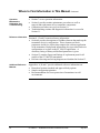
WHERE TO FIND INFORMATION IN THIS MANUAL
XIX
WHERE TO FIND INFORMATION IN THIS MANUAL CONTINUED
XX
ST 3000 FF FIELDBUS PRESSURE TRANSMITTER
XXI
OPERATIONAL NOTE
XXI
— IMPORTANT —
XXI
IMPORTANT
XXII
BEFORE YOU BEGIN, PLEASE NOTE
XXII
July 2011
ST 3000 FF - Installation and Device Reference Guide
v
Contents
SECTION 1 – ST 3000 FF DESCRIPTION
1
1.1
Introduction
1
1.2
CE Conformity
2
1.3
ST 3000 FF Transmitters
3
1.4
Fieldbus Overview
7
1.5
Transmitter Order
10
1.6
Local Meter Option
11
SECTION 2 — INSTALLATION OVERVIEW
13
2.1
Introduction
13
2.2
Advanced Diagnostics
14
2.3
Installation Components
16
2.4
Installation/Operation Tasks
18
SECTION 3 – OFF-LINE CONFIGURATION (OPTIONAL)
19
3.1
Introduction
19
3.2
Off-line Configuration
20
SECTION 4 – PRE-INSTALLATION CONSIDERATIONS
23
4.1
Introduction
23
4.2
Considerations for ST 3000 FF Transmitter
24
4.3
Considerations for Local Meter Option
28
SECTION 5 – TRANSMITTER INSTALLATION
29
5.1
Introduction
29
5.2
Mounting ST 3000 Transmitter
30
5.3
Piping ST 3000 Transmitter
42
5.4
Wiring ST 3000 FF Transmitter
47
5.5
Power Up Transmitter
57
vi
ST 3000 FF - Installation and Device Reference Guide
July 2011
Contents
SECTION 6 TRANSMITTER START-UP
58
6.1
Introduction
58
6.2
ST 3000 FF Communications
59
6.3
Checking Out the Transmitter
60
6.4
Verify Communications with Transmitter
62
6.5
Function Block Application Process
64
6.6
Setting Write Protect Feature
67
SECTION 7 OPERATION
70
7.1
Introduction
70
7.2
Operation Tasks
71
7.3
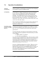
Operation Considerations
72
7.4
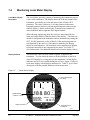
Monitoring Local Meter Display
74
7.4
Monitoring Local Meter Display Continued
75
7.5
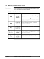
Changing Local Meter Display
78
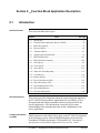
SECTION 8 FUNCTION BLOCK APPLICATION DESCRIPTION
80
8.1
Introduction
80
8.2
Function Block Application Process (FBAP)
81
8.3
Block Description
82
8.4
Resource Block
85
8.5
Transducer Block
90
8.6
Analog Input Function Block
100
8.7
PID Function Block
109
8.8
Block Parameter Summary
116
8.9
Link Objects
122
8.10
View Objects
123
July 2011
ST 3000 FF - Installation and Device Reference Guide
vii
Contents
8.11
Alert Objects
131
8.12
Alarm and Event Reporting
132
8.13
Trend Objects
133
8.14
Domain Objects
134
8.15
Device Description (DD)
135
8.16
Object Dictionary (OD)
137
8.17
Management Virtual Field Device (VFD)
141
8.18
System Management (SM)
142
8.19
Network Management
149
8.20
Resource Block Methods
151
8.21
Transducer Block Methods
157
8.22
Analog Input Block Methods
163
SECTION 9 MAINTENANCE
166
9.1
Introduction
166
9.2
Preventive Maintenance
167
9.3
Inspecting and Cleaning Barrier Diaphragms
168
9.4
Replacing Transmitter Electronics
172
9.5
Replacing Meter Body
177
9.6
Code Download
181
SECTION 10 CALIBRATION
183
10.1
Introduction
183
10.2
Overview
184
10.3
Calibration
185
viii
ST 3000 FF - Installation and Device Reference Guide
July 2011
Contents
SECTION 11 TROUBLESHOOTING
195
11.1
Introduction
195
11.2
Overview
196
11.3
Device Troubleshooting
197
11.4
Transmitter Faults
203
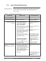
11.5
Non-Critical Fault Summary
206
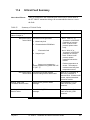
11.6
Critical Fault Summary
207
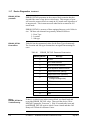
11.7
Device Diagnostics
208
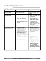
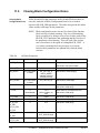
11.8
Block Configuration Errors
211
11.9
Clearing Block Configuration Errors
214
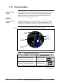
11.10
Simulation Mode
216
SECTION 12 PARTS LIST
12.1
Replacement Parts
218
218
SECTION 13 — REFERENCE DRAWINGS
238
13.1
Wiring Diagrams
238
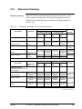
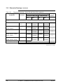
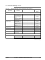
13.2
Dimension Drawings
239
APPENDIX A HAZARDOUS AREA CLASSIFICATIONS
244
A.1
North American Classification of Hazardous Locations
244
A.2
International Electrotechnical Commission (IEC) Classification of Hazardous Locations
253
A.3
Enclosure Ratings
258
A.4
Table III Options Reference
260
APPENDIX B —SAMPLE CONFIGURATION RECORD
263
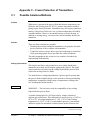
APPENDIX C – FREEZE PROTECTION OF TRANSMITTERS
277
C.1
Possible Solutions/Methods
July 2011
ST 3000 FF - Installation and Device Reference Guide
277
ix
Contents
x
ST 3000 FF - Installation and Device Reference Guide
July 2011
Tables
TABLE 1
TABLE 2
TABLE 3
TABLE 4
TABLE 5
TABLE 6
TABLE 7
TABLE 8
TABLE 9
TABLE 10
TABLE 11
TABLE 12
TABLE 13
TABLE 14
TABLE 15
TABLE 16
TABLE 17
TABLE 18
TABLE 19
TABLE 20
TABLE 21
TABLE 22
TABLE 23
TABLE 24
TABLE 25
TABLE 26
TABLE 27
TABLE 28
TABLE 29
TABLE 30
TABLE 31
TABLE 32
TABLE 33
TABLE 34
TABLE 35
TABLE 36
TABLE 37
TABLE 38
TABLE 39
TABLE 40
TABLE 41
TABLE 42
TABLE 43
TABLE 44
TABLE 45
TABLE 46
TABLE 47
TABLE 48
TABLE 49
July 2011
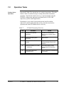
ADVANCED DIAGNOSTICS AVAILABILITY................................................................................. 14
COMPONENTS REQUIRED FOR ST 3000 FF INSTALLATION ..................................................... 16
INSTALLATION/OPERATION TASK SUMMARY........................................................................... 18
OFF-LINE CONFIGURATION WIRING PROCEDURE .................................................................... 20
OPERATING TEMPERATURE LIMITS (TRANSMITTERS WITH SILICONE FILL FLUIDS)..... 25
ST 3000 FF POWER REQUIREMENTS .............................................................................................. 26
TRANSMITTER MAXIMUM ALLOWABLE WORKING PRESSURE (MAWP) RATINGS.......... 27
LOCAL METER SPECIFICATIONS.................................................................................................... 28
MOUNTING ST 3000 FF TRANSMITTER TO A BRACKET............................................................ 31
ZERO CORRECTS PROCEDURE FOR STD110 ................................................................................ 36
MOUNTING REMOTE DIAPHRAGM SEAL TRANSMITTER ........................................................ 40
SUGGESTED TRANSMITTER LOCATION FOR GIVEN PROCESS .............................................. 43
PROCESS CONNECTIONS FOR TRANSMITTERS .......................................................................... 44
FLANGE DESCRIPTION...................................................................................................................... 45
INSTALLING FLANGE ADAPTER .................................................................................................... 46
FOUNDATION FIELDBUS PROFILE TYPES.................................................................................... 47
FIELDBUS CABLE TYPES .................................................................................................................. 50
ST 3000 FF WIRING TERMINALS ..................................................................................................... 53
WIRING THE TRANSMITTER............................................................................................................ 54
TRANSMITTER POWER UP PROCEDURE....................................................................................... 57
TRANSMITTER CHECKOUT TASKS ................................................................................................ 60
TRANSMITTER IDENTIFICATION. .................................................................................................. 62
CREATING AN FBAP FILE................................................................................................................. 65
HOW TO SET WRITE PROTECT JUMPER........................................................................................ 67
WRITE PROTECT JUMPER SETTINGS............................................................................................. 68
WRITE PROTECT FEATURE TRUTH TABLE.................................................................................. 69
ST 3000 FF OPERATING TASK LIST................................................................................................. 71
DESCRIPTION OF DISPLAY INDICATORS SHOWN IN FIGURE 25 ............................................ 75
SUMMARY OF TYPICAL LOCAL SMART METER INDICATIONS.............................................. 76
LOCAL METER FAULT INDICATIONS............................................................................................ 77
CHANGING LOCAL METER DISPLAY UNITS................................................................................ 78
FUNCTION BLOCK APPLICATION PROCESS ELEMENTS .......................................................... 82
BLOCK PARAMETER LIST COLUMN DESCRIPTION ................................................................... 84
RESOURCE BLOCK PARAMETERS.................................................................................................. 85
RESOURCE BLOCK PARAMETER DESCRIPTIONS....................................................................... 88
TRANSDUCER BLOCK PARAMETERS............................................................................................ 90
TRANSDUCER BLOCK PARAMETER DESCRIPTIONS ................................................................. 93
AI FUNCTION BLOCK PARAMETER LIST.................................................................................... 101
AI BLOCK PARAMETER DESCRIPTIONS ..................................................................................... 102
TRANSDUCER BLOCK PARAMETERS.......................................................................................... 103
AI BLOCK PARAMETERS ................................................................................................................ 105
AI BLOCK MODE RESTRICTED PARAMETERS .......................................................................... 108
PID CONTROL FUNCTION BLOCK PARAMETERS .................................................................... 109
HONEYWELL PID PARAMETERS .................................................................................................. 111
PID TUNING PARAMETER VALUES.............................................................................................. 114
PID BLOCK MODE RESTRICTED PARAMETERS ........................................................................ 115
TABLE DESCRIPTION FOR BLOCK PARAMETER SUMMARY................................................. 116
TRANSDUCER BLOCK PARAMETER SUMMARY....................................................................... 118
RESOURCE BLOCK PARAMETER SUMMARY ............................................................................ 120
ST 3000 FF - Installation and Device Reference Guide
xi
TABLE 50
ANALOG INPUT FUNCTION BLOCK PARAMETER SUMMARY ..............................................120
TABLE 51
PID FUNCTION BLOCK PARAMETER SUMMARY......................................................................120
TABLE 52
LINK OBJECTS DEFINED FOR ST 3000 FF ....................................................................................122
TABLE 53
VIEW LIST FOR RESOURCE BLOCK PARAMETERS ..................................................................124
TABLE 54
VIEW LIST FOR TRANSDUCER BLOCK PARAMETERS ............................................................126
TABLE 55
VIEW LIST FOR AI FUNCTION BLOCK PARAMETERS..............................................................128
TABLE 56
VIEW LIST FOR PID CONTROL FUNCTION BLOCK PARAMETERS.......................................129
TABLE 57
ST 3000 FF OBJECT DICTIONARY..................................................................................................138
TABLE 58
BLOCK PARAMETER INDEX TABLE.............................................................................................139
TABLE 59
ST 3000 FF SMIB OBJECT DICTIONARY .......................................................................................142
TABLE 60
SYSTEM MANAGEMENT SUPPORTED FEATURES ....................................................................143
TABLE 61
SM AGENT OBJECTS ........................................................................................................................144
TABLE 62
SM SYNC AND SCHEDULING OBJECTS .......................................................................................145
TABLE 63
SM ADDRESS ASSIGNMENT OBJECTS .........................................................................................146
TABLE 64
FUNCTION BLOCK SCHEDULING OBJECTS ...............................................................................148
TABLE 65
ST 3000 FF NMIB OBJECT DICTIONARY ......................................................................................150
TABLE 65
INSPECTING AND CLEANING BARRIER DIAPHRAGMS ..........................................................168
TABLE 66
PROCESS HEAD BOLT TORQUE RATINGS ..................................................................................171
TABLE 67
REPLACING SMART METER AND ELECTRONICS MODULE. ..................................................172
TABLE 68
REPLACING METER BODY ONLY .................................................................................................177
TABLE 69
CODE DOWNLOAD PROCEDURE ..................................................................................................181
TABLE 70
TRANSDUCER BLOCK CALIBRATION PARAMETERS ..............................................................186
TABLE 71
LOW AND HIGH TRIM POINT LIMITS FOR ST 3000 FF TRANSMITTERS..............................188
TABLE 72
TWO-POINT SENSOR CALIBRATION PROCEDURE ...................................................................189
TABLE 73
RESTORING FACTORY SENSOR CALIBRATION PROCEDURE ...............................................190
TABLE 74
CLEARING SENSOR CALIBRATION PROCEDURE .....................................................................192
TABLE 75
CORRECT ZERO SENSOR CALIBRATION PROCEDURE............................................................193
TABLE 76
LOCAL ZERO CORRECTION PROCEDURE...................................................................................194
TABLE 77
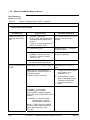
DEVICE TROUBLESHOOTING TABLE A ......................................................................................197
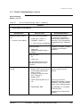
TABLE 78
DEVICE TROUBLESHOOTING TABLE B.......................................................................................198
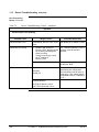
TABLE 79
DEVICE TROUBLESHOOTING TABLE C......................................................................................199
TABLE 80
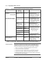
XD_DIAG_DETAIL PARAMETER BIT MAPPING.........................................................................203
TABLE 81
IDENTIFYING CRITICAL AND NON-CRITICAL DEVICE FAULTS...........................................204
TABLE 82
SUMMARY OF NON-CRITICAL FAULTS ......................................................................................206
TABLE 83
SUMMARY OF CRITICAL FAULTS ................................................................................................207
TABLE 84
AREAS OF DEVICE MEMORY WHERE DATA IS STORED. .......................................................208
TABLE 85
BLOCK_ERR PARAMETERBIT MAPPING.....................................................................................209
TABLE 86
ERROR_DETAIL PARAMETER ENUMERATION .........................................................................210
TABLE 87
SUMMARY OF CONFIGURATION ERRORS .................................................................................211
TABLE 88
AI BLOCK PARAMETERS ................................................................................................................214
TABLE 89
PID FUNCTION BLOCK PARAMETERS .........................................................................................215
TABLE 91
SIMULATION MODE TRUTH TABLE.............................................................................................217
TABLE 92
ST 3000 MOUNTING BRACKETS PARTS REFERENCE ...............................................................220
TABLE 93
PARTS IDENTIFICATION FOR CALLOUTS IN FIGURES 34 AND 35 ........................................222
TABLE 94
PARTS IDENTIFICATION FOR CALLOUTS IN FIGURE 36.........................................................224
TABLE 95
PARTS IDENTIFICATION FOR CALLOUTS IN FIGURE 37.........................................................227
TABLE 96
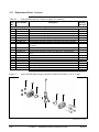
PARTS IDENTIFICATION FOR CALLOUTS IN FIGURE 38.........................................................228
TABLE 97
REPLACEMENT GP AND AP PROCESS HEAD PART NUMBERS FOR NARROW PROFILE
METER BODY................................................................................................................................................229
TABLE 98
PARTS IDENTIFICATION FOR CALLOUTS IN FIGURE 39.........................................................230
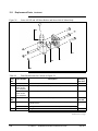
TABLE 99
PARTS IDENTIFICATION FOR CALLOUTS IN FIGURE 40.........................................................231
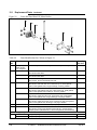
TABLE 100
PARTS IDENTIFICATION FOR CALLOUTS IN FIGURE 41 ....................................................232
xii
ST 3000 FF - Installation and Device Reference Guide
July 2011
TABLE 101
PARTS IDENTIFICATION FOR CALLOUTS IN FIGURE 42 .................................................... 234
TABLE 102
PARTS IDENTIFICATION FOR CALLOUTS IN FIGURE 43 .................................................... 235
TABLE 103
SUMMARY OF RECOMMENDED SPARE PARTS.................................................................... 237
TABLE 104
EXTERNAL WIRING DIAGRAMS .............................................................................................. 238
TABLE 105
DIMENSION DRAWINGS - SERIES 100 AND SERIES 900 ...................................................... 239
TABLE A-1
FACTORY MUTUAL (FM) ENTITY PARAMETERS................................................................. 248
TABLE A-2
CSA ENTITY PARAMETERS ....................................................................................................... 249
TABLE A-3
CENELEC / LCIE CERTIFICATION ........................... ERROR! BOOKMARK NOT DEFINED.
TABLE A-4
STANDARDS AUSTRALIA (LOSC) CERTIFICATIONERROR! BOOKMARK NOT DEFINED.
TABLE A-5
ZONE 2 (EUROPE) DECLARATION OF CONFORMITYERROR! BOOKMARK NOT DEFINED.
TABLE A-6
NEMA ENCLOSURE TYPE NUMBERS AND COMPARABLE IEC
ENCLOSURE
CLASSIFICATION ............................................................................................................................................ 259
TABLE C-1
TEMPERATURE RANGE OF FREEZE PROTECTION SYSTEMS ........................................... 286
TABLE C-2
STEAM PRESSURE VERSUS STEAM TEMPERATURE VALUES.......................................... 290
July 2011
ST 3000 FF - Installation and Device Reference Guide
xiii
Figures
FIGURE 1
TYPICAL ST 3000 FF DIFFERENTIAL PRESSURE TRANSMITTER...............................................3
FIGURE 2
FUNCTIONAL BLOCK DIAGRAM OF ST 3000 FF TRANSMITTER OPERATION........................4
FIGURE 3
ST 3000 FF PRESSURE TRANSMITTER FAMILY TREE...................................................................6
FIGURE 4
FIELDBUS CONNECTING CONTROL ROOM AND FIELD DEVICES ............................................7
FIGURE 5
FIELDBUS DEVICES CONTAIN DEVICE APPLICATIONS AND FUNCTION BLOCKS ..............9
FIGURE 6
TYPICAL ST 3000 FF TRANSMITTER ORDER COMPONENTS. ..................................................10
FIGURE 7
TYPICAL LOCAL METER FACEPLATE ...........................................................................................11
FIGURE 8
ST 3000 FF WITH LOCAL METER OPTION. ....................................................................................12
FIGURE 9
FIELDBUS NETWORK COMPONENTS ............................................................................................17
FIGURE 10
CONFIGURATION SETUP FIGURE. .............................................................................................20
FIGURE 11
TYPICAL MOUNTING AREA CONSIDERATIONS PRIOR TO INSTALLATION....................24
FIGURE 12
TYPICAL BRACKET MOUNTED INSTALLATIONS ..................................................................30
FIGURE 13
LEVELING AN ABSOLUTE PRESSURE TRANSMITTER..........................................................34
FIGURE 14
TYPICAL FLANGE MOUNTED TRANSMITTER INSTALLATION ..........................................37
FIGURE 15
TYPICAL FLUSH MOUNTED TRANSMITTER INSTALLATION .............................................38
FIGURE 16
TYPICAL PIPE AND FLANGE MOUNTED INSTALLATIONS ..................................................39
FIGURE 17
TYPICAL REMOTE DIAPHRAGM SEAL TRANSMITTER INSTALLATION. .........................41
FIGURE 18
TYPICAL 3-VALVE MANIFOLD AND BLOW-DOWN PIPING ARRANGEMENT. ................42
FIGURE 19
TYPICAL PIPING ARRANGEMENT FOR ½” NPT PROCESS CONNECTION .........................43
FIGURE 20
DAISY-CHAIN WIRING SCHEME ................................................................................................48
FIGURE 21
BUS WITH SPURS WIRING ...........................................................................................................49
FIGURE 22
FIELDBUS NETWORK USING TREE WIRING SCHEME ..........................................................49
FIGURE 23
ST 3000 TRANSMITTER TERMINAL BLOCKS...........................................................................52
FIGURE 24
WRITE PROTECT JUMPER LOCATION ON TRANSDUCER BOARD .....................................68
FIGURE 25
SMART METER DISPLAY..............................................................................................................74
FIGURE 26
FBAP BLOCK DIAGRAM ...............................................................................................................83
FIGURE 27
TRANSDUCER BLOCK DIAGRAM ..............................................................................................92
FIGURE 28
AI BLOCK DIAGRAM...................................................................................................................104
FIGURE 29
PID CONTROL BLOCK DIAGRAM.............................................................................................112
FIGURE 30
DISASSEMBLY OF DP TRANSMITTER PROCESS HEADS FROM METER BODY .............170
FIGURE 32
MAJOR ST 3000 FF SMART TRANSMITTER PARTS REFERENCE. ......................................219
FIGURE 33
ST 3000 MOUNTING BRACKET PARTS REFERENCE.............................................................220
FIGURE 34
SERIES 100 AND 900 ELECTRONICS HOUSING – ELECTRONICS/METER END. ..............221
FIGURE 35
SERIES 100 AND 900 ELECTRONICS HOUSING – TERMINAL BLOCK END .....................221
FIGURE 36
SERIES 100 AND SERIES 900 DP METER BODY FOR MODELS STD924 & STD930 C, D,
G, H, K, AND L AND STD974..........................................................................................................................223
FIGURE 37
SERIES 900 DP METER BODY FOR MODELS STD924 & STD930 A, B, E, F, AND J...........226
FIGURE 38
SERIES 100 GP AND AP METER BODIES AND SERIES 900 AP METER BODY..................228
FIGURE 39
SERIES 900 DUAL-HEAD GP METER BODIES.........................................................................230
FIGURE 40
SERIES 100 AND SERIES 900 LGP AND LAP METER BODY. ................................................231
FIGURE 41
SERIES 900 FLUSH MOUNT METER BODY. ............................................................................232
FIGURE 42
SERIES 100 AND SERIES 900 FLANGE MOUNTED METER BODY. .....................................233
FIGURE 43
HIGH TEMPERATURE METER BODY.......................................................................................235
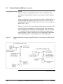
FIGURE C-1
PIPING INSTALLATION FOR SEALING LIQUID WITH SPECIFIC GRAVITY HEAVIER
THAN PROCESS FLUID.................................................................................................................................278
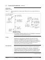
FIGURE C-2
PIPING INSTALLATION FOR SEALING LIQUID WITH SPECIFIC GRAVITY LIGHTER
THAN PROCESS FLUID................................................................................................................................279
FIGURE C-3
PIPING INSTALLATION FOR GAS FLOW.................................................................................280
xiv
ST 3000 FF - Installation and Device Reference Guide
July 2011
FIGURE C-4
PIPING INSTALLATION FOR DIFFERENTIAL PRESSURE TRANSMITTER WITH
METAL DIAPHRAGM SEALS. ....................................................................................................................... 281
FIGURE C-5
PIPING INSTALLATION FOR PROCESS PRESSURE TRANSMITTER WITH
METAL
DIAPHRAGM SEAL. ........................................................................................................................................ 282
FIGURE C-6
PIPING INSTALLATION FOR DIFFERENTIAL PRESSURE TRANSMITTER AND
IMPULSE PIPING WITH ELECTRIC HEATING AND CONTROL. ............................................................. 283
FIGURE C-7
PIPING INSTALLATION FOR PROCESS PRESSURE TRANSMITTER AND
IMPULSE
PIPING WITH ELECTRIC HEATING CONTROL.......................................................................................... 284
FIGURE C-8
PIPING INSTALLATION FOR DIFFERENTIAL PRESSURE TRANSMITTER AND IMPULSE
PIPING WITH STEAM HEATING. ............................................................................................................... 287
FIGURE C-9
PIPING INSTALLATION FOR PROCESS PRESSURE TRANSMITTER AND IMPULSE
PIPING WITH STEAM HEATING. ................................................................................................................ 288
July 2011
ST 3000 FF - Installation and Device Reference Guide
xv
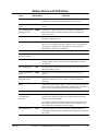
ABBREVIATIONS AND DEFINITIONS
Term
Abbreviation
Alarm
Definition
The detection of a block leaving a particular state and when it returns
back to that state.
Analog Input (function
block)
AI
One of the standard function blocks define by the Foundation
Fieldbus
Application
A software program that interacts with blocks, events and objects. One
application may interface with other applications or contain more than
one application.
Block
A logical software unit that makes up one named copy of a block and
the associated parameters its block type specifies. It can be a resource
block, transducer block or a function block.
Configuration (of a
system or device)
A step in system design: selecting functional units, assigning their
locations and identifiers, and defining their interconnections.
Device
A physical entity capable of performing one or more specific functions.
Examples include transmitters, actuators, controllers, operator
interfaces.
Device Description
DD
Description of FBAPs within a device. Files that describe the software
objects in a device, such as function blocks and parameters. The DD
binary are created by passing DD source files through a standard tool
called a tokenizer.
Device Description
Language
DDL
A standardized programming language (similar to C) used to write
device description source files.
Device Tag
The Physical Device Tag of the device as specified in the Foundation
Fieldbus specifications.
Event
An instantaneous occurrence that is significant to scheduling block
execution and to the operational (event) view of the application.
Field Device
A fieldbus-compatible device that contains and executes function
blocks.
FOUNDATION
Fieldbus
FF
Communications protocol for a digital, serial, two-way system which
interconnects industrial field equipment such as sensors, actuators and
controllers.
Function Block
FB
An executable software object that performs a specific task, such as
measurement or control, with inputs and outputs that connect to other
function blocks in a standard way.
Function Block
Application Process
FBAP
The part of the device software that executes the blocks (function,
transducer, or resource blocks).
Link Active Scheduler
LAS
A device which is responsible for keeping a link operational. The LAS
executes the link schedule, circulates tokens, distributes time messages
and probes for new devices.
Macrocycle
The least common multiple of all the loop times on a given link.
Manufacturer's Signal
Processing
MSP
A term used to describe signal processing in a device that is not defined
by FF specifications.
Continued on next page
xvi
ST 3000 FF - Installation and Device Reference Guide
July 2011
Abbreviations and Definitions
Term
Abbreviation
Definition
Network Management
NM
A part of the software and configuration data in a Foundation
Fieldbus device that handles the management of the network.
Network Management
Agent
NMA
Part of the device software that operates on network management
objects.
Network Management
Information Base
NMIB
A collection of objects and parameters comprising configuration,
performance and fault-related information for the communication
system of a device.
Objects
Entities within the FBAP, such as blocks, alert objects, trend objects,
parameters, display lists, etc.
Object Dictionary
OD
Parameters
Definitions and descriptions of network visible objects of a device.
There are various object dictionaries within a device. The dictionaries
contain objects and their associated parameters which support the
application in which they are contained.
A value or variable which resides in block objects
Proportional Integral
Derivative control
PID
Stack
A standard control algorithm. Also refers to a PID function block.
The software component that implement the Foundation Fieldbus
communications protocol specifications, including FMS, FAS, DLL,
SM and NM.
System Management
SM
Provides services that coordinate the operation of various devices in a
distributed fieldbus system.
System Management
Agent
SMA
Part of the device software that operates on system management
objects.
System Management
Information Base
SMIB
A collection of objects and parameters comprising configuration and
operational information used for control of system management
operations.
Status
A coded value that qualifies dynamic variables (parameters) in function
blocks. This value is usually passed along with the value from block to
block. Status is fully defined in the FF FBAP specifications.
Trim Point
A selected reference point at which a measurement is calibrated.
Virtual
Communication
Reference
VCR
A defined communication endpoint. Fieldbus communications can
primarily only take place along a active communications "path" that
consists of two VCR endpoints.
For example, to establish communications between a transducer block
and a function block, a VCR must be defined at the transducer block
and a VCR must be defined at the function block.
Virtual Field Device
July 2011
VFD
A logical grouping of "user layer" functions. Function blocks are
grouped into a VFD, and system and network management are grouped
into a VFD.
ST 3000 FF - Installation and Device Reference Guide
xvii
Technical Assistance
Contacts
World Wide Web
The following lists Honeywell’s World Wide Web sites that will be of interest to our customers.
Honeywell Organization
WWW Address (URL)
Corporate
http://www.honeywell.com
Honeywell Process Solutions
http://hpsweb.honeywell.com/ps
Technical tips
http://content.honeywell.com/ipc/faq
Telephone
Contact us by telephone at the numbers listed below.
Organization
United States and Canada
xviii
Honeywell
Phone Number
1-800-423-9883
1-800-525-7439
ST 3000 FF - Installation and Device Reference Guide
Tech. Support
Service
July 2011
Where to Find Information in This Manual
About this Manual
This manual provides installation, operation, maintenance for the
ST 3000 Series 100 Transmitter with Fieldbus FOUNDATION
communications option. Reference information is also provided.
The sections of information contained in the manual follow this order:
Background and Pre-installation
Transmitter mechanical and electrical installation
Transmitter configuration
Operation and maintenance
Reference Information
Background and
Pre-installation
Information
Sections 1 through 4 provide background and pre-installation information
if you are not familiar with the ST 3000 FF transmitter, or if this is a new
installation.
Section 1 covers the basic transmitter description.
Section 2 provides a listing of fieldbus network components and
installation tasks.
Section 3 provides a procedure for performing a bench check or
off-line configuration to the transmitter.
Section 4 gives installation and operating considerations before
you install the transmitter.
Transmitter
Installation
Procedures
Section 5 covers mechanical and electrical installation procedures for the
transmitter. These procedures instruct you on how to properly:
Mount the transmitter
Install piping to the transmitter
Make the electrical connections and
Apply power to the transmitter.
Transmitter
Configuration
Section 6 tells you how to configure the transmitter so it will operate
according to your process application. This information outlines the
configuration procedure which can be done through an operator station or
host computer. (An example showing a sample configuration of the
transmitter’s parameters is listed in Appendix B.)
Continued on next page
July 2011
ST 3000 FF - Installation and Device Reference Guide
xix
Where to Find Information in This Manual Continued
Operation,
Maintenance,
Calibration and
Troubleshooting
Reference Information
Sections 8, 12 and13 contain reference information:
Section 8 provides descriptions of fieldbus elements that make up the
transmitter (device) configuration. These elements are block
parameters and device objects that comprise the software application
of the transmitter. Background information also is provided on device
configuration as it relates to the ST 3000 FF application. A
dictionary listing of Honeywell-defined parameters is given.
Section 12 contains figures and listings of replacement parts for all
models of the ST 3000 FF transmitters.
Reference drawings and wiring diagrams are furnished in Section 13.
Additional Reference
Material
Appendixes A, B and C provide additional reference information on:
Hazardous location standards and approval body options
Sample configuration printouts.
Recommendations for freeze protection of transmitters in cold
environments.
xx
ST 3000 FF - Installation and Device Reference Guide
Section 7 covers operation information.
Section 9 provides routine maintenance procedures as well as
removal and replacement of key transmitter components.
Calibration procedures are given in Section 10.
Troubleshooting routines and diagnostic information is covered in
Section 11.
July 2011
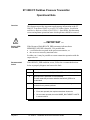
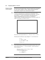
ST 3000 FF Fieldbus Pressure Transmitter
Operational Note
Overview
This document provides important supplementary information to the ST
3000 FF Transmitter With FOUNDATION™ Fieldbus Option, Installation
and Device Reference Guide, #34-ST-25-15. Specifically, this document
covers an important operational note which operators should be aware of.
— IMPORTANT —
BLOCK_ERR
Indication
If the Resource Block BLOCK_ERR parameter indicates that a
MEMORY FAILURE is detected. It is possible that:
a real failure has occurred in the processor memories, or
the error was caused by transient noise.
In either case, it may be possible to restore transmitter operation with the
suspect device.
Recommended
Action
If this BLOCK_ERR condition occurs, follow the recommended actions
below to properly diagnose and correct the fault.
Step
Action
1
Write Resource block MODE_BLK.TARGET to Out of Service (O/S).
2
Write RESTART parameter to PROCESSOR.
This will restart the processor and allow the BLOCK_ERR to be
recalculated.
July 2011
3
Allow the transmitter to run for 10 seconds so that the diagnostic
rechecks for any memory failures.
4
After 10 seconds, if:
Errors are reported, then replace transmitter electronics.
No errors are reported, then write MODE_BLK.TARGET to AUTO
in resource block.
ST 3000 FF - Installation and Device Reference Guide
xxi
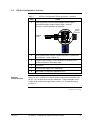
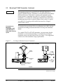
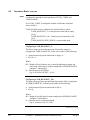
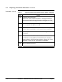
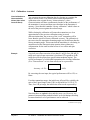
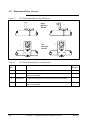
IMPORTANT
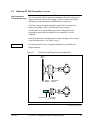
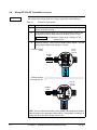
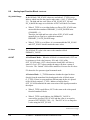
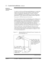
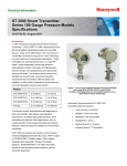
Before You Begin, Please Note
Depending on your transmitter options, the transmitter may be equipped
with either a 3-screw or 5-screw terminal block inside the electronics
housing. This may affect how to connect the fieldbus cable wiring to
the transmitter. See Section 5.4 for the terminal block connections for
each type terminal. Section 13 provides additional wiring diagrams
showing alternate wiring methods.
SIGNAL
- SIGNAL +
Electronics
Housing
Terminal
Block
+
-
METER
+
TEST
L+
-
SIGNAL
Electronics
Housing
Terminal
Block
+
-
+
-
TEST
Transmitter Terminal
Blocks
Internal
Ground
Terminal
Internal
Ground
Terminal
3-Screw Terminal Block
xxii
5-Screw Terminal Block
ST 3000 FF - Installation and Device Reference Guide
July 2011
Section 1 – ST 3000 FF Description
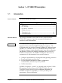
1.1
Introduction
Section Contents
This section includes these topics:
Section
Topic
See Page
1.1 Introduction .............................................................................................1
1.2 CE Conformity .........................................................................................2
1.3 ST 3000 FF Transmitters.........................................................................3
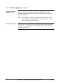
About this Section
ATTENTION
1.4
Fieldbus Overview...................................................................................7
1.5
Transmitter Order ..................................................................................10
1.6
Local Meter Option ...............................................................................11
This section is intended for users who have never worked with our
ST 3000 FF Transmitter. It provides some general information to
acquaint you with the transmitter.
For communication, configuration and monitoring of the ST 3000 FF
transmitter, Honeywell offers NI-FBUS Configurator software. The
Configurator runs on a variety of Personal Computer (PC) platforms using
Windows® 95 or Windows NT™. It is a bundled Windows software and
PC-interface hardware solution that allows quick, error-free configuration
and diagnosis of Honeywell Smartline instruments with FOUNDATION
Fieldbus communications. The NI-FBUS Configurator allows users to
communicate with the transmitter from a remote location to:
Configure the transmitter by selecting and setting operating parameters.
Request and display transmitter data.
Access diagnostic information to identify configuration,
communication, transmitter or process problems.
Calibrate transmitter.
NI-FBUS Configurator, version 2.3 is compatible with our latest ST 3000
FF transmitters. Refer to Honeywell ST 3000 FF Fieldbus Pressure
Transmitter Software Release Guide for additional information on
NI-FBUS Configurator compatibility, or contact your Honeywell
representative for more information.
July 2011
ST 3000 FF - Installation and Device Reference Guide
1
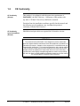
1.2
CE Conformity
CE Conformity
(Europe)
This product is in conformity with the protection requirements of
2004/108/EC, the EMC Directive. Conformity of this product with
any other “CE Mark” Directive(s) shall not be assumed.
Deviation from the installation conditions specified in this manual, and
the following special conditions, may invalidate this product’s
conformity with the EMC Directive.
CE Conformity
Special Conditions
(Europe)
Shielded twisted pair cables are required for I/O interface circuits.
ATTENTION
The emission limits of EN 50081-2 are designed to provide reasonable
protection against harmful interference when this equipment is operated in an
industrial environment. Operation of this equipment in a residential area may
cause harmful interference. This equipment generates, uses, and can radiate
radio frequency energy and may cause interference to radio and television
reception when the equipment is used closer than 30 m to the antenna(e). In
special cases, when highly susceptible apparatus is used in close proximity,
the user may have to employ additional mitigating measures to further reduce
the electromagnetic emissions of this equipment.
2
ST 3000 FF - Installation and Device Reference Guide
July 2011
1.3
ST 3000 FF Transmitters
About the Transmitter
The ST 3000 Transmitter with FF option is furnished with FOUNDATION
Fieldbus interface to operate in a compatible distributed fieldbus system.
The transmitter will interoperate with any FOUNDATION -registered
device. See Section 1.4 for an overview of fieldbus.
The transmitter includes FOUNDATION Fieldbus electronics for operating
in a 31.25 kbit/s fieldbus network. It features standard fieldbus function
blocks with manufacturer-specific additions for enhanced operation. This
transmitter can function as a Link Active Scheduler in a fieldbus network.
The ST 3000 FF comes in a variety of models for measurement
applications involving one of these basic types of pressure:
Differential Pressure
Gauge Pressure
Absolute Pressure
The transmitter measures the process pressure and transmits a digital
output signal proportional to the measured variable over a two-wire pair.
Its major components are an electronics housing and a meter body as
shown in Figure 1 for a typical differential pressure model transmitter.
Figure 1
Typical ST 3000 FF Differential Pressure Transmitter.
Electronics
Housing
Meter Body
Continued on next page
July 2011
ST 3000 FF - Installation and Device Reference Guide
3
1.3
ST 3000 FF Transmitters Continued
About the Transmitter, The ST 3000 transmits its output in a digital fieldbus protocol format for
continued
direct digital communications with control systems.
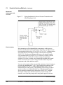
The Process Variable (PV) is available for monitoring and control
purposes (maximum update rate for PV is 8 times per second). The
meter body temperature is also available as a secondary variable for
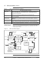
monitoring purposes only through the operator interface. Figure 2 shows
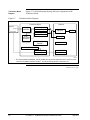
a block diagram of the ST 3000 FF operating functions.
Figure 2
Functional Block Diagram of ST 3000 FF Transmitter Operation
Factory
Characterization
Data
Configuration
Data
Electronics Housing
Meter Body
EEPROM
EEPROM
Temperature
Sensor
Static Pressure
Sensor
Multiplexer
DP or AP
Sensor
A/D
Microprocessor
Microprocessor
Digital I/O
(MAU)
Transducer Board
Broadcasts
digital signal for
31.25 kbit/s
Fieldbus
Stack Board
Pressure
Terminal Block
24095
Continued on next page
4
ST 3000 FF - Installation and Device Reference Guide
July 2011
1.3
ST 3000 FF Transmitters Continued
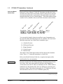
Series and Model
Number Data
Honeywell’s line of Smart ST 3000 FF Transmitters includes the Series
100 and Series 900 with several models to meet various process pressure
measurement and interface requirements. Each transmitter comes with a
nameplate that lists its given “model number”. The model number format
consists of a Key Number with several Table selections as shown below.
ic
p
Ty
e
o
rB
e
s
et
Ba
M
Key Number Table I
dy
ge
an
As
Fl
Table II
m
se
b
ly
ns
tio
p
O
Table III
r
to
y
I
n
de
i
tif
tio
ca
n
c
Fa
Table IV
STD120 - E1A- 00000 -SB,2J ,FF-XXXX
You can quickly identify what series and basic type of transmitter you
have from the third and fourth digits in the key number. The letter in the
third digit represents one of these basic transmitter types:
A = Absolute Pressure
D = Differential Pressure
F = Flange Mounted
G = Gauge Pressure
R = Remote Seals
The number in the fourth digit matches the first digit in the transmitter
Series. Thus, a “1” means the transmitter is a Series 100.
Refer to the Model Selection Guide for a complete description of the
model number for your transmitter.
ATTENTION
Previous versions of the ST 3000 transmitter with designations of Series
100, Series 100e, Series 600, and Series 900 have been supplied at
various times since the ST 3000 was introduced in 1983. While all these
transmitters are functionally alike, there are differences in housing and
electronics design. This manual only applies for ST 3000 Series 100 and
900 transmitters with FOUNDATION Fieldbus option (FF).
Continued on next page
July 2011
ST 3000 FF - Installation and Device Reference Guide
5
1.3
ST 3000 FF Transmitters Continued
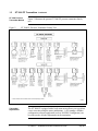
ST 3000 Pressure
Transmitter Models
Figure 3
Figure 3 illustrates the present ST 3000 FF pressure transmitter family
tree.
ST 3000 FF Pressure Transmitter Family Tree.
Transmitter
Adjustments
The ST 3000 FF equipped with a local smart meter allows you to perform
a zero correction using the meter pushbuttons. A PC running a fieldbus
configuration software application (such as NI-FBUS Configurator) can
be used to make all other adjustments in the transmitter.
6
ST 3000 FF - Installation and Device Reference Guide
July 2011
1.4
Fieldbus Overview
What is Fieldbus
Fieldbus is an all digital, serial, two-way communication system which
interconnects industrial "field" equipment such as sensors, actuators, and
controllers. Fieldbus is a Local Area Network (LAN) for field
instruments with built-in capability to distribute the control application
across the network. See Figure 4.
Figure 4
Fieldbus Connecting Control Room and Field Devices
Control Room
Device
(Operator
Interface)
Fieldbus LAN
ST 3000
FF
ST 3000
FF
Fieldbus
Device
Fieldbus
Device
24097
Open System Design
The Foundation Fieldbus has defined standards to which field devices
and operator/control stations communicate with one another. The
communications protocol is built as an "open system" to allow all field
devices and control equipment which are built to fieldbus standards to be
integrated into a control system, regardless of the device manufacturer.
This interoperability of devices using fieldbus technology is to become
the industry standard for automation and distributed control systems.
Continued on next page
July 2011
ST 3000 FF - Installation and Device Reference Guide
7
1.4
Fieldbus Overview Continued
Hardware
Architecture
The physical architecture of fieldbus allows installation of fieldbus
devices using a twisted-pair cable. Often, existing wiring from analog
devices can be used to wire up digital fieldbus devices. Multiple field
devices can be connected on one cable (a multi-drop link), rather than
conventional point-to-point wiring used for analog devices. For more
details on wiring fieldbus networks, see Section 5.4.
Software Architecture
Fieldbus software architecture provides for more control functions to be
available in the microprocessor-based field device. Since fieldbus is a
digital communication system, more data is available to operators for
process monitoring, trend analysis, report generation, and trouble
analysis. Device software changes can be downloaded to field devices
remotely from the operator station (or PC) in the control room.
Application
An application is software that contains function block data and
operating parameters (objects) which help define the operation of a
device such as, sensor data acquisition or control algorithm processing.
Some devices may contain more than one application.
Function Blocks
Usually, a device has a set of functions it can perform. These functions
are represented as function blocks within the device. See Figure 5.
Function blocks are software that provide a general structure for
specifying different device functions. Each function block is capable of
performing a control function or algorithm. Device functions may
include analog input, analog output, and Proportional Integral Derivative
(PID) control. These blocks can be connected together to build a process
loop. The action of these blocks can be changed by adjusting the block's
configuration and operating parameters.
Continued on next page
8
ST 3000 FF - Installation and Device Reference Guide
July 2011
1.4
Fieldbus Overview Continued
Figure 5
Fieldbus Devices Contain Device Applications and Function Blocks
Fieldbus Device
Device Application
Function Block
Function Block
Block Parameters
Block Parameters
Function Block
Function Block
Block Parameters
Block Parameters
Fieldbus LAN
24098
ST3000 FF
Transmitter
Application
The ST 3000 FF Fieldbus Transmitter contains the electronics interface
compatible for connecting to a fieldbus network. ST 3000 FF application
is configured using a fieldbus configuration software program. The
configurator software allows the user to configure blocks, change
operating parameters and create linkages between blocks that make up
the ST 3000 application. The changes to the ST 3000 application are
then written to the device and initialized.
July 2011
ST 3000 FF - Installation and Device Reference Guide
9
1.5
Transmitter Order
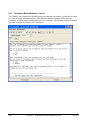
Order Components
Figure 6
Figure 6 shows the components that would be shipped and received for
a typical ST 3000 FF transmitter.
Typical ST 3000 FF Transmitter Order Components.
Ordered
* Series 100 ST 3000 FF Differential pressure transmitter with optional mounting bracket
Received
Shipped
ST 3000 FF
Installation and
Device Reference
Manual
Mounting Bracket (Optional)
Device
Description
Diskette
DD
24099
About Documentation
ST 3000 FF Transmitter Installation and Device Reference Manual, 34ST-25-15 provides information for checking, installing, wiring and
configuring the ST 3000 FF transmitter for operation. Also, a Software
Release Guide is included with the transmitter which contains additional
operational information for a specific software revision.
Device Description
Diskette
Also, a diskette is shipped with the transmitter containing the device
description and standard dictionary files for the transmitter. These files,
when used in conjunction with the PC-based fieldbus configuration
application, provide an on-line description and displays of the transmitter
operation. See Device Description in Section 8.
10
ST 3000 FF - Installation and Device Reference Guide
July 2011
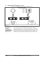
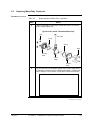
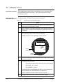
1.6
Local Meter Option
Option Availability
The ST 3000 FF can be equipped with a Local Meter option as shown in
Figure 7. The local meter provides read-only output value of the Analog
Input block OUT parameter in both % of span and in actual engineering
units. See Section 7.4 for additional details of the meter. (See Section
7.5 for the procedure to select engineering units for the local meter
display.
Figure 7
Typical Local Meter Faceplate
VAR
SEL.
SPAN
UPPER
VALUE
0
%
100
UNITS
SET
ZERO
Local Meter Panel
Pushbutons
LOWER
VALUE
The ZERO pushbutton on the meter panel can be used to perform a zerocorrection to the transmitter. See Section 10, Calibration for the
procedure.
Continued on next page
July 2011
ST 3000 FF - Installation and Device Reference Guide
11
1.6
Local Meter Option Continued
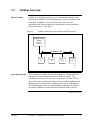
About the option
The Local Meter is a separate assembly that is designed to snap fit on the
transmitter’s electronics module. The option assembly includes a cable
and plug assembly for mating with a connector on the transmitter’s
transducer electronics board. A meter end-cap which includes a window
is supplied on the electronics side of the transmitter’s housing so you can
view the meter display with the end cap installed. See Figure 8.
Figure 8
ST 3000 FF with Local Meter Option.
Electronics
Housing
Local Smart
Meter Option
24122
12
ST 3000 FF - Installation and Device Reference Guide
July 2011
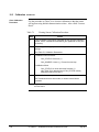
Section 2 — Installation Overview
2.1
Introduction
Section Contents
This section includes these topics:
Section
Topic
See Page
2.1 Introduction ...........................................................................................13
2.2 Advanced Diagnostics ..........................................................................14
2.3 Installation Components ........................................................................16
2.4 Installation/Operation Tasks ………………………………………….18
About this Section
This section provides a list of components needed to install and operate
the ST 3000 FF transmitter. Also provided is a list of typical start-up
tasks and places where you can find detailed information about
performing the tasks.
July 2011
ST 3000 FF - Installation and Device Reference Guide
13
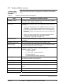
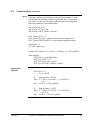
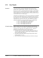
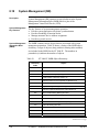
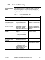
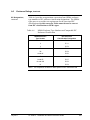
2.2
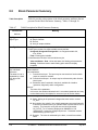
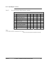
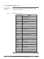
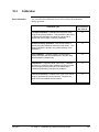
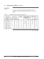
Advanced Diagnostics
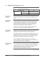
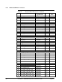
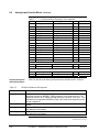
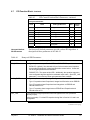
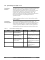
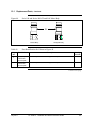
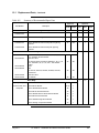
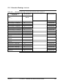
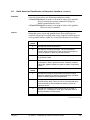
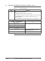
See table below for Advanced Diagnostic availability in your instrument. Use National Instruments or other configurator
to obtain revision information from the resource block’s REVISION_ARRAY, DEV_REV and DD_REV parameters and
use that information to pick appropriate revision combination column 1 thru 4 in table below.
Use designation and notes from the appropriate column to determine level of availability of each Advanced Diagnostic
feature. The notes at end of the table explain situations where a feature is only partially available.
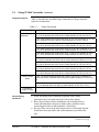
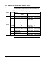
Table 1
Advanced Diagnostics Availability
Table 1 – Advanced Diagnostic Feature Availability by Firmware/Hardware Revision Combination
Revision Combination
1
2
3
4
RS Block: REVISION_ARRAY[0]
RS Block: REVISION_ARRAY[2]
RS Block: DEV_REV, DD_REV
#
1
2
3
4
5
6
7
8
9
10
11
12
13
14
15
16
17
18
19
20
21
22
23
24
Advanced Diagnostic Feature
INSTALL_DATE
TIME_IN_SERVICE
POWER_CYCLES
POWER_CYCLES_DATE
VOLTAGE
VOLTAGE_MIN
VOLTAGE_MIN_DATE
EL_TEMPERATURE
Electronics Temperature Tracking:
EL_TEMP_OVER_RNG_CTR
EL_TEMP_OVER_RNG_DATE
EL_TEMP_UNDER_RNG_CTR
EL_TEMP_UNDER_RNG_DATE
EL_TEMP_MAX
EL_TEMP_MIN
MSG_KEY_NUMBER
MSG_METER_BODY
MSG_FLANGE
MSG_OPTIONS_1
MSG_OPTIONS_2
Device SW Revisions
Device RS Block Information
Materials of Construction:
Model Number:
Device Key Number and Meter Body
Information
Device Flange Assembly Information
14
0402 + below
0103 + below
08,02 + below
0501 + above
0103 + below
09,01 + above
0501 + above
0104 + above
09,01 + above
0501 + above
0105 + above
09,01 + above
Type
N/A
N/A
N/A
N/A
N/A
N/A
N/A
N/A
F/F
F/F
F/F
F/F
0.0 Note 6
0.0 Note 6
1/1/72 Note 6
0.0 Note 6
F/F
F/F
F/F
F/F
0.0 Note 6
0.0 Note 6
1/1/72 Note 6
0.0 Note 6
F/F
F/F
F/F
F/F
F/F
F/F
F/F
F/F
Parameter
Parameter
Parameter
Parameter
Parameter
Parameter
Parameter
Parameter
N/A
N/A
N/A
N/A
N/A
N/A
N/A
N/A
N/A
N/A
N/A
N/A
N/A
0 Note 6
1/1/72 Note 6
0 Note 6
1/1/72 Note 6
0.0 Note 6
0.0 Note 6
Note 2
Note 2
Note 2
Note 2
Note 2
F/F
F/F
0 Note 6
1/1/72 Note 6
0 Note 6
1/1/72 Note 6
0.0 Note 6
0.0 Note 6
F/F
F/F
F/F
F/F
F/F
F/F
F/F
F/F
F/F
F/F
F/F
F/F
F/F
F/F
F/F
F/F
F/F
F/F
F/F
F/F
Parameter
Parameter
Parameter
Parameter
Parameter
Parameter
Parameter
Parameter
Parameter
Parameter
Parameter
Method
Method
N/A
N/A
Note 2
Note 2
F/F
F/F
F/F
F/F
Method
Method
N/A
Note 2
F/F
F/F
Method
ST 3000 FF - Installation and Device Reference Guide
July 2011
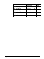
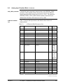
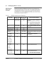
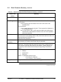
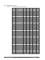
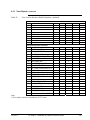
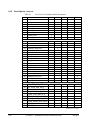
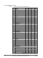
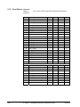
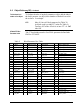
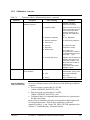
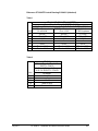
Table 1 – Advanced Diagnostic Feature Availability by Firmware/Hardware Revision Combination – Continued
Revision Combination
1
2
3
4
RS Block: REVISION_ARRAY[0]
RS Block: REVISION_ARRAY[2]
RS Block: DEV_REV, DD_REV
#
39
40
41
42
43
44
45
46
47
48
49
50
51
52
Advanced Diagnostic Feature
Process Variable Tracking:
PV_MAX
PV_MIN
AI Block Information
PV_OVER_RNG_CTR
PV_OVER_RNG_DATE
PV_UNDER_RNG_CTR
PV_UNDER_RNG_DATE
Meter Body Temperature Tracking:
TEMP_OVER_RNG_CTR
TEMP_OVER_RNG_DATE
TEMP_UNDER_RNG_CTR
TEMP_UNDER_RNG_DATE
TEMP_MAX
TEMP_MIN
ST_PR
Static Pressure Tracking:
ST_PR_MAX
ST_PR_OVER_RNG_CTR
ST_PR_OVER_RNG_DATE
STRESS_MONITOR
SERVICE_LIFE
CALIB_DATE_LAST_2PT
CALIB_DATE_PREV_2PT
CALIB_DATE_RESTORE
CALIB_DATE_CLEAR
CALIB_DATE_ZERO
XD Block Information
Two-point Calibration
Restore Calibration
Clear Calibration
53
Calibration Zero
25
26
27
28
29
30
31
32
33
34
35
36
37
38
N/A = Not Available.
0402 + below
0103 + below
08,02 + below
0501 + above
0103 + below
09,01 + above
0501 + above
0104 + above
09,01 + above
0501 + above
0105 + above
09,01 + above
N/A
N/A
N/A
N/A
N/A
N/A
N/A
F/F
F/F
F/F
F/F
F/F
F/F
F/F
F/F
F/F
F/F
F/F
F/F
F/F
F/F
F/F
F/F
F/F
F/F
F/F
F/F
F/F
Parameter
Parameter
Method
Parameter
Parameter
Parameter
Parameter
Type
N/A
N/A
N/A
N/A
N/A
N/A
N/A
F/F
F/F
F/F
F/F
F/F
F/F
0.0 Note 6
F/F
F/F
F/F
F/F
F/F
F/F
Note 5
F/F
F/F
F/F
F/F
F/F
F/F
Note 5
Parameter
Parameter
Parameter
Parameter
Parameter
Parameter
Parameter
N/A
N/A
N/A
N/A
N/A
N/A
N/A
N/A
N/A
N/A
N/A
N/A
N/A
N/A
0.0 Note 6
0 Note 6
1/1/72 Note 6
Note 3
Note 4
F/F
F/F
F/F
F/F
F/F
F/F
F/F
F/F
F/F
Note 5
Note 5
Note 5
Note 3
Note 4
F/F
F/F
F/F
F/F
F/F
F/F
F/F
F/F
F/F
Note 5
Note 5
Note 5
F/F
F/F
F/F
F/F
F/F
F/F
F/F
F/F
F/F
F/F
F/F
Parameter
Parameter
Parameter
Parameter
Parameter
Parameter
Parameter
Parameter
Parameter
Parameter
Method
Method
Method
Method
F/F
F/F
N/A
F/F
Method
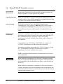
F/F = Feature has full functionality
Note 2: Model number not available data is blank.
Note 3: Feature is functional but missing effect of electronics temperature.
Note 4: Service life calculated as if electronics temperature was constant at 0C
Note 5: Future Feature to be added for DP meter body types; static pressure is 0.0 for AP and GP type meter bodies.
Note 6: Feature is not functional. The displayed value is fixed at value indicated in table.
July 2011
ST 3000 FF - Installation and Device Reference Guide
15
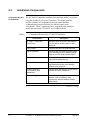
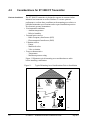
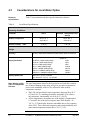
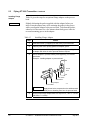
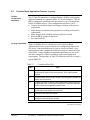
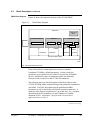
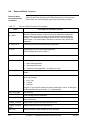
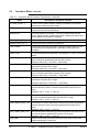
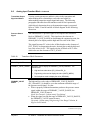
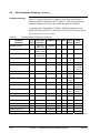
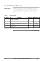
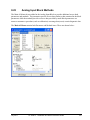
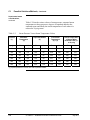
2.3
Installation Components
Components Needed
for Installation
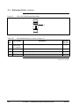
Table 2
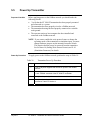
The ST 3000 FF transmitter contains electronics that enable it to operate
using the Fieldbus FOUNDATION protocol. This digital interface
requires a number of components to provide control and data
communications between field devices and the control room
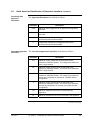
environment. Table 1 outlines the basic component parts needed to
install and operate the ST 3000 FF on a fieldbus network
Components Required for ST 3000 FF Installation
Components
Description
ST 3000 FF Transmitter
(Field Device)
Measures process pressure and transmits
process data to operator station or host
computer.
Power Supply
Furnishes DC power to fieldbus devices.
Power Conditioner
Acts as a filter to prevent the power supply
from interfering with the fieldbus signaling.
(May be part of a fieldbus power supply.)
Fieldbus Cable
Twisted pair shielded wire used to
interconnect fieldbus devices.
Fieldbus Terminators
A signal termination device used to prevent
reflected signals (noise) from distorting
fieldbus communications.
Fieldbus IS Barriers
(For hazardous area
installations)
Intrinsic safety wire barriers are required for
hazardous location installations.
Fieldbus Wiring Blocks
Wiring blocks allowing easy connection of
devices, cable, terminators, surge
suppressors and other fieldbus network
components.
Continued on next page
16
ST 3000 FF - Installation and Device Reference Guide
July 2011
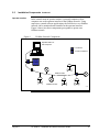
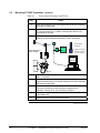
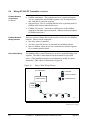
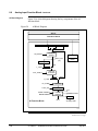
2.3
Installation Components Continued
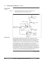
In the control room an operator station, a personal computer or host
computer acts as the operator interface to the fieldbus network. Using
supervisory control software applications, the field devices on a fieldbus
network can be monitored and controlled at the operator interface.
Figure 9 shows how these components go together to operate on a
fieldbus network.
Operator Interface
Figure 9
Fieldbus Network Components
Operator Station or
Host Computer
T
= Terminator
PC = Power Conditioner
Power
Supply
PC
T
Fieldbus Cable
T
Fieldbus Devices
24100
July 2011
ST 3000 FF - Installation and Device Reference Guide
17
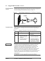
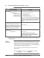
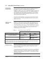
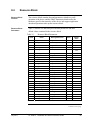
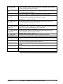
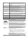
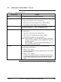
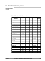
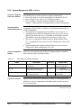
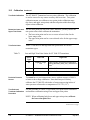
2.4
Installation/Operation Tasks
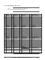
Installation Tasks
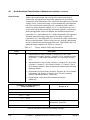
Installation of the ST 3000 FF is not difficult. The tasks for installing and
operating the transmitter are outlined in Table 2.
Table 3
Installation/Operation Task Summary
Task
Procedure
-
Bench Check (optional)
(Off-line configuration)
Section 3
1
Pre-installation Considerations
Section 4
2
Install ST 3000 FF Transmitter
Section 5
Mounting
Section 5.2
Piping
Section 5.3
Wiring
Section 5.4
3
Power Up Transmitter
Section 5.5
4
Establish Communications
Section 6.4
18
Refer to . . .
Initial checks
5
Configure ST 3000 FF
transmitter
Section 6.5 in this manual and
also the user manual supplied
with your fieldbus configuration
application.
6
Operation
Section 7. Also see supervisory
control application
documentation.
-
Periodic Maintenance
Section 9
Cleaning
Section 9.3
Calibration
Section 10
-
Troubleshooting (if problems
arise)
Section 11
-
Replacement (if needed)
Section 9
ST 3000 FF - Installation and Device Reference Guide
July 2011
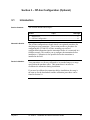
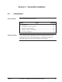
Section 3 – Off-line Configuration (Optional)
3.1
Introduction
Section Contents
This section includes these topics
Section
Topic
See Page
3.1 Introduction ...........................................................................................17
3.2 Off-line Configuration...........................................................................18
About this Section
The off-line configuration or bench check is an optional procedure for
checking out your transmitter. This section provides a procedure for
configuring the ST 3000 FF off-line, meaning you can load
configuration information into the transmitter before it is connected in a
fieldbus network. This enables you to configure the transmitter before
installation. Calibration is also possible before the transmitter is
installed in the field.
Device Calibration
Your transmitter was factory calibrated to its standard range or a range
specified on the purchase order. This means there is no need to
recalibrate the transmitter during installation.
If you need to calibrate the transmitter before installation, the setup is
the same as for the benchcheck and the calibration procedures can be
found in Section 10.
July 2011
ST 3000 FF - Installation and Device Reference Guide
19
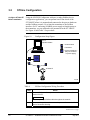
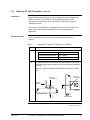
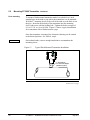
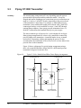
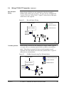
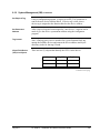
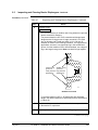
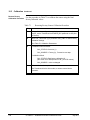
3.2
Off-line Configuration
Configure ST 3000 FF
Before Installation
Using the NI-FBUS Configurator software (or other fieldbus device
configuration application), you can perform an off-line check of the
ST 3000 FF before it is mounted and connected to the process hardware
and the fieldbus network. By wiring the transmitter to the fieldbus
interface of a PC and using a fieldbus power supply to furnish power to
the transmitter, you can read and write parameters in the ST 3000 FF.
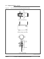
See Figure 10 and Table 3 for procedure.
Figure 10
Configuration Setup Figure.
PC or
Operator Station
J
= Junction Block
T
= Terminator
PC = Power Conditioner *
(May be contained
in power supply)
PC
*
Power
Supply
T
J
T
ST 3000 FF
24101B
Table 4
Step
1
Off-line Configuration Wiring Procedure
Action
Connect fieldbus cable to junction block and to fieldbus interface
card on the PC.
Observe polarity of fieldbus cable throughout the network.
2
Loosen end-cap lock and remove end-cap cover from terminal block
end of electronics housing.
Continued on next page
20
ST 3000 FF - Installation and Device Reference Guide
July 2011
3.2
Off-line Configuration Continued
Table 3
Off-line Configuration Wiring procedure, continued
Step
3
Action
Observing polarity, connect positive fieldbus lead to Signal +
terminal and negative fieldbus lead to Signal – terminal.
Establish
Communications
+
-
Internal
Ground
Terminal
+
TEST
Fieldbus
Cable
- SIGNAL +
Example: Connecting fieldbus to transmitter.
4
At the junction block, connect a fieldbus terminator in parallel with
the transmitter. Refer to Figure 10.
5
Connect a power supply , power conditioner (if needed), and a
fieldbus terminator to the fieldbus cable.
6
Turn on PC.
7
Turn on power supply on the fieldbus link.
8
Start fieldbus configuration application on PC.
Once you have established communications between the transmitter and
the PC, you can then check out the transmitter. If the transmitter is not
visible in the configurator application window, see Troubleshooting in
Section 11.
Continued on next page
July 2011
ST 3000 FF - Installation and Device Reference Guide
21
3.2
Off-line Configuration Continued
Assign Bus Address
and Device Tag
You can check the device ID, sensor ID and SENSOR_SN of the
transmitter, assign a network node address to the device and assign tag
names to the device.
NOTE: The transmitter is shipped with default node addresses and tag
names that appear at start-up. These can be changed to actual
network addresses and tag names.
Device Configuration
You can view the various block parameters that make up the transmitter
configuration, enter parameter values for your process application and
write them to the device.
22
ST 3000 FF - Installation and Device Reference Guide
July 2011
Section 4 – Pre-Installation Considerations
4.1
Introduction
Section Contents
This section includes these topics:
Section
Topic
See Page
4.1 Introduction ...........................................................................................21
4.2 Considerations for ST 3000 FF Transmitter..........................................22
4.3 Considerations for Local Meter Option................................................26
About this Section
This section reviews things you should take into consideration before
you install the transmitter. Of course, if you are replacing an existing
ST 3000 FF transmitter you can skip this section
July 2011
ST 3000 FF - Installation and Device Reference Guide
23
4.2
Considerations for ST 3000 FF Transmitter
Evaluate Conditions
•
•
•
•
The ST 3000 FF transmitter is designed to operate in common indoor
industrial environments as well as outdoors. To assure optimum
performance, evaluate these conditions at the mounting area relative to
published transmitter specifications and accepted installation practices
for electronic pressure transmitters.
Environmental conditions
– Ambient temperature
– Relative humidity
Potential noise sources
– Radio Frequency Interference (RFI)
– Electromagnetic Interference (EMI)
Vibration sources
– Pumps
– Motorized valves
– Valve cavitation
Process characteristics
– Temperature
– Maximum pressure rating
Figure 11 illustrates typical mounting area considerations to make
before installing a transmitter.
Figure 11
Typical Mounting Area Considerations Prior to Installation
Lightning
(EMI)
Ambient
Temperature
Relative
Humidity
Large Fan Motors
(EMI)
Transceivers
(RFI)
Pump
(vibration)
Meter Body
Temperature
21003
Continued on next page
24
ST 3000 FF - Installation and Device Reference Guide
July 2011
4.2
Considerations for ST 3000 FF Transmitter Continued
Table 4 lists the operating temperature limits for the various types of
transmitters with silicone fill fluids. See transmitter specifications for
the temperature limits of transmitters with alternative fill fluids.
Temperature limits
Table 5
Operating Temperature Limits (Transmitters with Silicone Fill Fluids)
Transmitter Type and Model
Ambient Temperature
Meter Body
°C
°F
°C
°F
STD110
-40 to 70
-40 to 158
-40 to 70
-40 to 158
Differential Pressure STD125
-40 to 85
-40 to 185
-40 to 85
-40 to 185
STD120, STD130, STD170
-40 to 93
-40 to 200
-40 to 125
-40 to 257
STD924, STD930, STD974
-40 to 85
-40 to 185
-40 to 125
-40 to 257
STG140, STG170, STG180,
STG14L, STG17L, STG18L
-40 to 93
-40 to 200
-40 to 125
-40 to 257
STG14T
-40 to 93
-40 to 200
-40 to 150 †
-40 to 302 †
STG93P
-15 to 65
5 to 149
-15 to 95 ††
STG944, STG974
-40 to 85
-40 to 185
-40 to 125
-40 to 257
STG94L, STG97L, STG98L
-40 to 85
-40 to 185
-40 to 110
-40 to 230
-40 to 93
-40 to 200
STA140/14L
-40 to 93
-40 to 200
STA922/92L
-40 to 85
-40 to 185
STA940/94L
-40 to 85
-40 to 185
-40 to 80
-40 to 176
STA17L/97L
-40 to 85
-40 to 185
-40 to 80
-40 to 176
Flange Mounted
STF128, STF132, STF924,
STF932
-40 to 93
-40 to 200
-40 to 175
-40 to 350
Pseudo-Flanged Head
STF12F, STF13F, STF92F,
STF93F
-40 to 93
-40 to 200
-40 to 93
-40 to 200
STF14F
-40 to 85
-40 to 185
-40 to 85
-40 to 185
Gauge Pressure Flange Mount
STF14T
-40 to 93
-40 to 200
-40 to 150 †
-40 to 302 †
Draft Range
Gauge Pressure
Absolute Pressure STA122/12L
5 to 203 ††
See Specification Sheet
-40 to 80
-40 to 176
See Specification Sheet
Remote Diaphragm Seals
STR12D, STR13D, STR14G,
STR17G, STR14A
STR93D, STR94G
See Specification Sheet
-40 to 85
-40 to 185
See Specification Sheet
See Specification Sheet
†
Process temperatures above 125 °C (257 °F) require a reduction in the maximum ambient temperature as follows:
Process Temperature
Ambient Temperature Limit
150 °C (302 °F)
50 °C (122 °F)
140 °C (284 °F)
60 °C (140 °F)
125 °C (257 °F)
85 °C (185 °F)
†† Process temperatures above 65 °C (149 °F) require a 1:1 reduction in maximum ambient temperature.
NOTE: For transmitters with local meter option see Table 7.
NOTE: Transmitters with other fill fluids (CTFE, Neobee, Etc.) have different Operating Temperature Limits. For more
specific information, refer to the appropriate Specification and Model Selection Guide or transmitter nameplate.
July 2011
ST 3000 FF - Installation and Device Reference Guide
25
4.2
Considerations for ST 3000 FF Transmitter Continued
Power Requirements
The ST 3000 FF is a bus-powered device, meaning that it receives its
power from the dc voltage on a fieldbus wiring segment. There are
certain guidelines and limitations regarding the wiring of fieldbus
devices. See Section 5.4 for more information on wiring the transmitter.
Table 5 lists the operating power requirements for the ST 3000 FF
transmitter.
Table 6
ST 3000 FF Power Requirements
Static Power
Minimum
Maximum
9 Vdc @ 20mA
32 Vdc @ 20mA
(at the transmitter
terminal block)
For additional information on power requirements see the Honeywell ST 3000 FF Fieldbus
Pressure Transmitter Software Release Guide.
Continued on next page
26
ST 3000 FF - Installation and Device Reference Guide
July 2011
4.2
Considerations for ST 3000 FF Transmitter Continued
Pressure Ratings
Table 7
Table 6 lists Maximum Allowable Working Pressure (MAWP) for a given
transmitter Upper Range Limit (URL).
The maximum allowable working pressure (MAWP) is the pressure
used for the approval body safety calculations.
Transmitter Maximum Allowable Working Pressure (MAWP) Ratings
Transmitter Type
Upper Range Limit
(URL)
MAWP
Draft Range
10 inches H2O (25
mbar)
50 psi (3.5 bar)
400 inches H2O (1 bar)
3,000 psi (210 bar)
100 psi (7 bar)
3,000 psi (210 bar)
3,000 psi (210 bar)
3,000 psi (210 bar)
100 psi (7 bar)
100 psi (7 bar)
300 psi (21 bar)
300 psi (21 bar)
500 psi (35 bar)
500 psi (35 bar)
3,000 psi (210 bar)
3,000 psi (210 bar)
Differential Pressure
Gauge Pressure
Flange Mount
6,000 psi (415 bar)
6,000 psi (415 bar)
10,000 psi (690 bar)
10,000 psi (690 bar)
400 inches H2O (1 bar)
Per selected flange and
material (ANSI/ASME
150#, 300#, DN PN40)
100 psi (7 bar)
Remote Seal
Absolute Pressure
400 inches H2O (1 bar)
100 psi (7 bar)
Lesser MAWP of either
Remote Seal selected or
transmitter pressure
rating
780 mmHg Absolute
(1 bar)
780 mmHg Absolute (1
bar)
500 psia (35 bar)
500 psia (35 bar)
3,000 psia (210 barA)
3,000 psia (210 barA)
NOTE: Maximum Allowable Working Pressure (MAWP) may vary with materials of construction and process
temperature. For more specific information, refer to the appropriate Specification and Model Selection
Guide or transmitter nameplate
NOTE: To convert bar values to kilopascals (kPa), multiply by 100.
For example, 3.5 bar equals 350 kPa
July 2011
ST 3000 FF - Installation and Device Reference Guide
27
4.3
Considerations for Local Meter Option
Table 7 lists pertinent local meter specifications for reference.
Reference
Specifications
Table 8
Local Meter Specifications.
Operating Conditions
Parameter
Ambient Temperature
Relative Humidity
%RH
Rated
Extreme, Transportation and
Storage
–40 to 176 F
–40 to 80 C
–58 to 194 F
–50 to 90 C
10 to 90
0 to 100
Design
Accuracy
No error. Reproduces transmitter signal exactly within its resolution.
Display Resolution
0.005 for 19.99 reading range,
0.05 for 199.9 reading range,
0.5 for 1999 reading range,
5 for 19990 reading range,
50 for 199900 reading range,
500 for 1999000 reading range,
50000 for 19990000 reading range.
Display Update Rate
Above 32 F (0 C): ½ second
@ or below 32 F (0 C): 1½ seconds.
Shown as:
19.99
199.9
1999
19.99 K
199.9 K
1999 K
19990 K
Meter Display at High
and Low Temperature
Extremes
The rated temperature limits for the local meter are listed above and are
true in that no damage to the meter will occur over these temperatures,
however the readability of the LCD is affected if taken to these
temperature extremes:
The LCD will turn black at some temperature between 80 to 90 C
(176 and 194 F), rendering the display unreadable. This effect is
only temporary, and normally occurs at 90 C (194 F).
At low temperatures, the update rate of the display is lengthened to
1.5 seconds` due to the slower response time of the display. At
-20 C (-4 F) the display becomes unreadable due to slow response
of the LCD. This is also only temporary and normal readability will
return when temperature returns above -20 C (-4 F).
28
ST 3000 FF - Installation and Device Reference Guide
July 2011
Section 5 – Transmitter Installation
5.1
Introduction
Section Contents
This section includes these topics:
Section
Topic
See Page
5.1 Introduction ...........................................................................................27
5.2 Mounting ST 3000 Transmitter.............................................................28
5.3 Piping ST 3000 Transmitter ..................................................................38
5.4 Wiring ST 3000 FF Transmitter............................................................43
5.5 Power up Transmitter ............................................................................53
About this Section
This section provides information about the mechanical and electrical
installation of the ST 3000 FF transmitter. It includes procedures for
mounting, piping and wiring the transmitter for operation.
July 2011
ST 3000 FF - Installation and Device Reference Guide
29
5.2
Summary
Mounting ST 3000 Transmitter
You can mount all transmitter models (except flush mount models and
those with integral flanges) to a 2-inch (50 millimeter) vertical or
horizontal pipe using our optional angle or flat mounting bracket or a
bracket of your own. Flush mount models are mounted directly to the
process pipe or tank by a 1-inch weld nipple. Those models with
integral flanges are supported by the flange connection.
Figure 12 shows typical bracket and flange mounted transmitter
installations for comparison.
Figure 12
Typical Bracket Mounted Installations
Angle
Mounting
Bracket
Flat
Mounting
Bracket
Horizontal Pipe
Tank
Wall
Flange
Connection
Transmitter
Flange
Continued on next page
30
ST 3000 FF - Installation and Device Reference Guide
July 2011
5.2
Mounting ST 3000 Transmitter Continued
Dimensions
Detailed dimension drawings for given transmitter series and types are
listed in Section 13 for reference. Note that abbreviated overall
dimensions are also shown in the Specification Sheets for the given
transmitter models.
This section assumes that the mounting dimensions have already been
taken into account and the mounting area can accommodate the
transmitter.
Bracket mounting
Table 8 summarizes typical steps for mounting a transmitter to a
bracket.
Table 9
Mounting ST 3000 FF Transmitter to a Bracket
Step
Action
1
2
If you are using an…
optional mounting bracket
Then…
go to Step 2.
existing mounting bracket
go to Step 3.
Position bracket on 2-inch (50.8 mm) or, and install “U” bolt around
pipe and through holes in bracket. Secure with nuts and lockwashers
provided.
Example - Angle mounting bracket secured to horizontal or vertical
pipe.
Nuts and
Lockwashers
Nuts and
Lockwashers
Mounting
Bracket
U-Bolt
Mounting
Bracket
Horizontal Pipe
U-Bolt
Vertical Pipe
Continued on next page
July 2011
ST 3000 FF - Installation and Device Reference Guide
31
5.2
Mounting ST 3000 Transmitter Continued
Bracket mounting,
continued
Table 8
Mounting ST 3000 FF Transmitter to a Bracket, continued
Step
3
Action
Align appropriate mounting holes in transmitter with holes in bracket
and secure with bolts and washers provided.
If transmitter is …
DP type with double-ended
process heads and/or
remote seals
Then …
use alternate mounting
holes in end of heads.
GP and AP with singleended head
use mounting holes in side
of meter body.
In-line GP and AP
use smaller “U” bolt
provided to attach meter
body to bracket.
See figure below.
Dual head GP and AP
use mounting holes in end
of process head.
Inline models
Meter Body
Smaller
“U” bolt
Use bracket for
hexagonal meter body
NOTE: If the meter body is hexagonal, you must use the additional
bracket supplied. If meter body is round, discard the
bracket.
Continued on next page
32
ST 3000 FF - Installation and Device Reference Guide
July 2011
5.2
Mounting ST 3000 Transmitter Continued
Bracket mounting,
continued
Table 8
Mounting ST 3000 FF Transmitter to a Bracket, continued
Step
4
Action
Loosen 4 mm set screw on outside neck of transmitter one full turn.
Rotate electronics housing a maximum of 180 degrees in the left or
right direction from center to the position you require and tighten set
screw (13 to 15 lb-in/1.46 to 1.68 N.m).
Example - Rotating electronics housing.
180 degrees
max.
Electronics
Housing
180 degrees
max.
Set Screw
Continued on next page
July 2011
ST 3000 FF - Installation and Device Reference Guide
33
5.2
Mounting ST 3000 Transmitter Continued
The mounting position of a model STA122, STA922, STA12L or
STA922 Absolute Pressure Transmitter or a model STD110 Draft Range
Differential Pressure Transmitter is critical as the transmitter spans
become smaller. A maximum zero shift of 2.5 mm Hg for an absolute
transmitter or 1.5 in H2O for a draft range transmitter can result from a
mounting position which is rotated 90 degrees from vertical. A typical
zero shift of 0.12 mm Hg or 0.20 in H2O can occur for a 5 degree
rotation from vertical.
Precautions for
Mounting
Transmitters with
Small Absolute or
Differential Pressure
Spans
Figure 13
To minimize these positional effects on calibration (zero shift), take the
appropriate mounting precautions that follow for the given transmitter
model.
For a model STA122 or STA922 transmitter, you must ensure that the
transmitter is vertical when mounting it. You do this by leveling the
transmitter side-to-side and front-to-back. See Figure 13 for suggestions
on how to level the transmitter using a spirit balance.
Leveling an Absolute Pressure Transmitter.
Leveling Absolute Pressure models
Center
Section
Process
Head
Position spirit balance on
center section of meter
body only.
Cont’d
Continued on next page
34
ST 3000 FF - Installation and Device Reference Guide
July 2011
5.2
Mounting ST 3000 Transmitter Continued
Figure 13 Leveling an Absolute Pressure Transmitter (cont’d)
Leveling Inline models
Mount transmitter vertically to assure best accuracy. Position spirit balance on pressure connection surface
of AP body.
Precautions for
Mounting
Transmitters with
Small Absolute or
Differential Pressure
Spans, continued
For a transmitter with a small differential pressure span, you must
ensure that the transmitter is vertical when mounting it. You do this by
leveling the transmitter side-to-side and front-to-back. See Figure 13 for
suggestions on how to level the transmitter using a spirit balance. You
must also zero the transmitter by following the steps in Table 9 below.
July 2011
ST 3000 FF - Installation and Device Reference Guide
35
5.2
Mounting ST 3000 Transmitter Continued
Table 10
Zero Corrects Procedure for STD110
Step
Action
1
Attach the transmitter to the mounting bracket but do not completely
tighten the mounting bolts
2
Connect a tube between the input connections in the high pressure
(HP) and low pressure (LP) heads to eliminate the affects of any
surrounding air currents.
3
Connect an operator interface and transmitter to a fieldbus link and
power up the link to read the transmitter’s output. See figure.
T
T
J
PC
Differential Pressure
Type Transmitter
*
Power
Supply
J
= Junction Block
T
= Terminator
PC
= Power Conditioner *
(May be contained
in power supply)
Fieldbus
Network
Interface
Tube
4
Establish communications with the transmitter. Follow the steps in
Table 3, if needed.
5
While reading the transmitter’s output (AI block OUT parameter)
position the transmitter so the output reading is zero and completely
tighten the mounting bolts
6
Perform an input zero correct function to correct for any minor error
that may occur after the mounting bolts are tightened. See
Calibration, Section 10 for zero correction procedure.
7
Remove the tube from between the input connections and the power
to the fieldbus link.
8
Continue with the remaining installation tasks.
Continued on next page
36
ST 3000 FF - Installation and Device Reference Guide
July 2011
5.2
Mounting ST 3000 Transmitter Continued
Flange mounting
To mount a flange mounted transmitter model, bolt the transmitter’s
flange to the flange pipe on the wall of the tank.
On insulated tanks, remove enough insulation to accommodate the
flange extension.
Figure 14 shows a typical installation for a transmitter with the flange
on the high pressure (HP) side so the HP diaphragm is in direct contact
with the process fluid. The low pressure (LP) side of the transmitter is
vented to atmosphere (no connection).
It is the End User’s responsibility to provide a flange gasket and mounting hardware that are suitable for the
transmitter’s service condition.
To prevent degradation of performance in Flush-Mounted Flanged Transmitters, exercise care to ensure
that the internal diameter of the flange gasket does not obstruct the sensing diaphragm.
To prevent degradation of performance in Extended Mount Flanged Transmitters, ensure that there
is sufficient clearance in front of the sensing diaphragm body.
Figure 14
Typical Flange Mounted Transmitter Installation
Attention: Dotted area indicates use
with closed tank with reference leg.
Maximum Level
Variable
Head H1
Reference
Leg
Minimum Level
HP Side
mounted
to tank
LP Side vented
to atmosphere
Continued on next page
July 2011
ST 3000 FF - Installation and Device Reference Guide
37
5.2
Mounting ST 3000 Transmitter Continued
Flush mounting
To mount a flush mounted transmitter model, cut a hole for a 1-inch
standard pipe in the tank or pipe where the transmitter is to be mounted.
Weld the 1” mounting sleeve to the wall of the tank or to the hole cut on
the pipe. Insert the meter body of the transmitter into the mounting
sleeve and secure with the locking bolt. Tighten the bolt to a torque of
8.1 to 13.5 N · m ( 6 to 10 ft-lb). Figure 15 shows a typical installation
for a transmitter with a flush mount on a pipe.
Once the transmitter is mounted, the electronics housing can be rotated
to the desired position. See Table 8, step 4.
On insulated tanks, remove enough insulation to accommodate the
mounting sleeve.
Figure 15
Typical Flush Mounted Transmitter Installation
1" Pipe Mount 316 SS Weld Nipple
(standard option)
Continued on next page
38
ST 3000 FF - Installation and Device Reference Guide
July 2011
5.2
Mounting ST 3000 Transmitter Continued
High Temperature
Transmitter Mounting
You can mount the High Temperature transmitter directly to the process
flange connection or the process piping. Figure 16 shows typical pipe
and flange mounted transmitter installations for comparison.
To mount a flange mounted transmitter model, bolt the transmitter’s
flange to the flange on the wall of the tank or process pipe.
It is the End User’s responsibility to provide a flange gasket and
mounting hardware that are suitable for the transmitter’s service
condition.
Once the transmitter is mounted, the electronics housing can be rotated
to the desired position. See Table 8, step 4.
On insulated tanks, remove enough insulation to accommodate the
flange extension.
Figure 16
Typical Pipe and Flange Mounted Installations
Tank
Wall
Flange
Connection
Process Pipe
Transmitter
Flange
1/2" NPT
Connection
Continued on next page
July 2011
ST 3000 FF - Installation and Device Reference Guide
39
5.2
Mounting ST 3000 Transmitter Continued
Remote seal
mounting
Use the procedure in Table 10 to mount a remote diaphragm seal
transmitter model. Figure 17 shows a typical installation for a remote
diaphragm seal transmitter for reference.
Mount the transmitter flanges within the limits stated here for the given
fill-fluid in the capillary tubes with a tank at one atmosphere.
IF the fill fluid is…
THEN mount the flange…
Silicone DC 200 Oil
no greater than 22 feet (6.7 meters)
below the transmitter.
Silicone DC 704 Oil
no greater than 19 feet (5.8 meters)
below the transmitter.
Chlorotrifluorethylene (CTFE)
no greater than 11 feet (3.4 meters)
below the transmitter.
NOTE: The combination of tank vacuum and high pressure capillary
head effect should not exceed 9 psi (300 mm Hg) absolute.
Table 11
Mounting Remote Diaphragm Seal Transmitter
Step
1
2
Action
Mount transmitter at a remote distance determined by length of
capillary tubing.
If Transmitter Model
Number is…
STR93D or STR12D
STR13D
Then Connect Remote
Seal on…
high pressure (HP) side of
transmitter to lower flange
mounting on tank wall for
variable head H1.
low pressure (LP) side of
transmitter to lower flange
mounting on tank wall for
variable head H1.
On insulated tanks, remove enough insulation to
accommodate the flange extension.
Continued on next page
40
ST 3000 FF - Installation and Device Reference Guide
July 2011
5.2
Mounting ST 3000 Transmitter Continued
Remote seal
mounting, continued
Table 10
Mounting Remote Diaphragm Seal Transmitter, Continued
Step
Action
3
If Transmitter Model
Number is…
STR93D or STR12D
Then Connect Remote
Seal on…
low pressure (LP) side of
transmitter to upper flange
mounting on tank wall for
fixed or constant head H2.
STR13D
high pressure (HP) side of
transmitter to upper flange
mounting on tank wall for
fixed or constant head H2.
On insulated tanks, remove enough insulation to
accommodate the flange extension.
4
Figure 17
It is the End User’s responsibility to provide a flange gasket and
mounting hardware that are suitable for the transmitter’s service
condition
Typical Remote Diaphragm Seal Transmitter Installation.
LP Side
- Model STR93D
- Model STR12D
HP Side
- Model STR13D
Maximum Level
H2
Fixed
Ref. Leg
Variable
Head H1
Minimum Level
HP Side
- Model STR93D
- Model STR12D
LP Side
- Model STR13D
July 2011
ST 3000 FF - Installation and Device Reference Guide
41
5.3
Summary
Piping ST 3000 Transmitter
The actual piping arrangement will vary depending upon the process
measurement requirements and the transmitter model. Except for
flanged and remote diaphragm seal connections, process connections are
made to ¼ inch or ½ inch NPT female connections in the process head
of the transmitter’s meter body. For example, a differential pressure
transmitter comes with double-ended process heads with ¼ inch NPT
connections but they can be modified to accept ½ inch NPT through
optional flange adapters. Some gauge pressure transmitters have a ½
inch NPT connection which mounts directly to a process pipe.
The most common type of pipe used is ½ inch schedule 80 steel pipe.
Many piping arrangements use a three-valve manifold to connect the
process piping to the transmitter. A manifold makes it easy to install
and remove a transmitter without interrupting the process. It also
accommodates the installation of blow-down valves to clear debris from
pressure lines to the transmitter.
Figure 18 shows a diagram of a typical piping arrangement using a
three-valve manifold and blow-down lines for a differential pressure
transmitter being used to measure flow.
Figure 18
Typical 3-Valve Manifold and Blow-Down Piping Arrangement.
To Downstream Tap
Blow-Down
Valve
To Upstream Tap
Blow-Down
Valve
3-Valve
Manifold
Blow-Down
Piping
Blow-Down
Piping
To Low Pressure
Side of Transmitter
To High Pressure
Side of Transmitter
To Waste
To Waste
Continued on next page
42
ST 3000 FF - Installation and Device Reference Guide
July 2011
5.3
Piping ST 3000 Transmitter Continued
Piping Arrangements,
continued
Another piping arrangement uses a block-off valve and a tee connector in
the process piping to the transmitter as shown in Figure 19.
Figure 19
Typical Piping Arrangement for ½” NPT Process Connection
Tank Wall
1/2" NPT
Connection
Block-off Valve
Transmitter location
Table 11 lists the mounting location for the transmitter depending on
the process.
Table 12
Process
Suggested Transmitter Location for Given Process
Suggested Location
Explanation
Gases
Above the gas line
The condensate drains away from
the transmitter.
Liquids
1. Below but close to the
elevation of the process
connection.
1. This minimizes the static head
effect of the condensate.
2. Level with or above the
process connection.
2. This requires a siphon to
protect the transmitter from
process steam. The siphon
retains water as a “fill fluid.”
For liquid or steam, the piping should slope a minimum of 25.4 mm
(1 inch) per 305 mm (1 foot). Slope the piping down towards the
transmitter if the transmitter is below the process connection so the
bubbles may rise back into the piping through the liquid. If the
transmitter is located above the process connection, the piping should
rise vertically above the transmitter; then slope down towards the
flowline with a vent valve at the high point. For gas measurement, use a
condensate leg and drain at the low point (freeze protection may be
required here).
See Appendix C for some suggested freeze protection solutions.
Continued on next page
July 2011
ST 3000 FF - Installation and Device Reference Guide
43
5.3
Piping ST 3000 Transmitter Continued
Care must be taken when installing transmitters on hot processes. The
operating temperature limits for the device (as outlined in Table 4) must
not be exceeded. Impulse piping may be used to reduce the temperature
of the process that comes into contact with the transmitter meter body.
As a general rule there is a 56 degree C drop (100 degree F) in the
temperature of the process for every foot of ½-inch uninsulated piping.
Process Connections
Table 12 describes typical process connections for a given type of
transmitter.
Table 13
Process Connections for Transmitters
Transmitter Type
Differential
Pressure
Process Connection
Gauge Pressure
Absolute Pressure
Flange Mounted
Liquid Level
Process heads with 1/4-inch NPT female connection.
Flange adapters and manifolds with 1/2-inch female
connection are optional.
Models with pseudo flange on one side include 2- or 3inch ANSI class 150 flange.
Process head with 1/2-inch NPT female connection
(Series 100 transmitters).
In-line 1/2-inch NPT female connection (STGxxL).
In-line ½-inch M-NPT, 9/16 AMINCO, DIN19213
Process heads with 1/4-inch NPT female connection
(STG9x4).
Flange adapters and manifolds with 1/2-inch female
connections are optional STG9x4).
2-inch Sanitary Tri-Clamp (STG1xT)
Flush mount in 1” weld sleeve, with O-ring and locking
bolt.
Process head with 1/2-inch NPT female connection.
(STAx22, x40).
In-line ½-inch M-NPT, 9/16 AMINCO, DIN19213
Small flange 1/2-inch, 1-, 1 ½ - and 2-inch (STFxxT)
2, 3- or 4-inch flange with flush or 2-, 4- or 6-inch
extended diaphragm (See Table 13) on high pressure
side.*
DN 50, 80, or 100 PN 40 flange with flush or 2, 4 or 6
inch extended diaphragm (See Table 13) on High
Pressure Side*.
Remote
Diaphragm Seals
See Model Selection Guide for description of available
Flanged, Threaded, Chemical Tee, Saddle, and Sanitary
process connections.
* Reference side has standard differential pressure process head.
Continued on next page
44
ST 3000 FF - Installation and Device Reference Guide
July 2011
5.3
Piping ST 3000 Transmitter Continued
Flange descriptions
Table 13 describes the available flange connections for flange mounted
liquid level transmitters.
Table 14
Transmitter Type
Flush or Extended
Diaphragm
Flange Description
Description
2-inch 150# serrated–face flange with 4 holes 19 mm (3/4 in) diameter on 120.7
mm (4.75 in) diameter bolt circle and an outside diameter of 150 mm (5.91 in).
2-inch 150# serrated–face flange with 8 holes 19 mm (3/4 in) diameter on 127 mm
(5.00 in) diameter bolt circle and an outside diameter of 165 mm (6.50 in).
3-inch 150# serrated–face flange with 4 holes 19 mm (3/4 in) diameter on 152.4
mm (6.00 in) diameter bolt circle and an outside diameter of 190 mm (7.48 in).
3-inch 300# serrated–face flange with 8 holes 22.2 mm (7/8 in) diameter on 168.3
mm (6.62 in) diameter bolt circle and an outside diameter of 210 mm (8.27 in).
4-inch 150# serrated–face flange with 4 holes 19 mm (3/4 in) diameter on 190.5
mm (7.50 in) diameter bolt circle and an outside diameter of 230 mm (9.05 in).
4-inch 300# serrated–face flange with 8 holes 22.2 mm (7/8 in) diameter on 255
mm (10.04 in) diameter bolt circle and an outside diameter of 200 mm (7.87 in).
DN 50 PN 40 serrated–face flange with 4 holes 18 mm (0.71 in) diameter on 125
mm (4.92 in) diameter bolt circle and an outside diameter of 165 mm (6.50 in).
DN 80 PN 40 serrated–face flange with 8 holes 18 mm (0.71 in) diameter on 160
mm (6.30 in) diameter bolt circle and an outside diameter of 200 mm (7.87 in).
DN 100 PN 40 serrated–face flange with 8 holes 22 mm (0.87 in) diameter on 190
mm (7.48 in) diameter bolt circle and an outside diameter of 235 mm (9.25 in).
Pseudo Flange
Head
2-inch, 150 lbs serrated-face flange with 4 holes 15.9 mm (5/8 in) diameter on
120.6 mm (4-3/4 in) diameter bolt circle and an outside diameter of 152.4 mm (6
in).
3-inch, 150 lbs serrated-face flange with 4 holes 19 mm (3/4 in) diameter on 152
mm (6 in) diameter bolt circle and an outside diameter of 190 mm (7-1/2 in).
Flush Mount
Gauge STG93P
General Piping
Guidelines
25.4 mm (1-inch) pipe mount. (316L SS standard option.)
When measuring fluids containing suspended solids, install
permanent valves at regular intervals to blow-down piping.
Blow-down all lines on new installations with compressed air or
steam and flush them with process fluids (where possible) before
connecting these lines to the transmitter’s meter body.
Be sure all the valves in the blow-down lines are closed tight after the
initial blow-down procedure and each maintenance procedure after
that.
Continued on next page
July 2011
ST 3000 FF - Installation and Device Reference Guide
45
5.3
Piping ST 3000 Transmitter Continued
Installing Flange
Adapter
Table 14 gives the steps for an optional flange adapter on the process
head.
Slightly deforming the gasket supplied with the adapter before you
insert it into the adapter may aid in retaining the gasket in the groove
while you align the adapter to the process head. To deform the gasket,
submerse it in hot water for a few minutes then firmly press it into its
recessed mounting groove in the adapter.
Table 15
Step
Installing Flange Adapter
Action
1
Insert filter screen (if supplied) into inlet cavity of process head.
2
Carefully seat Teflon (white) gasket into adapter groove.
3
Thread adapter onto 1/2-inch process pipe and align mounting holes
in adapter with holes in end of process head as required.
4
Secure adapter to process head by hand tightening 7/16-20 hexhead bolts.
Example - Installing adapter on process head.
Process
Head
Filter Screen
Teflon Gasket
Flange Adapter
7/16 x 20 Bolts
21011
Apply an anti-seize compound on the stainless steel
bolts prior to threading them into the process head.
5
46
Evenly torque flange adapter bolts to a torque of 27,1 Nm +/- 1,4 Nm
(20 ft lbs +/- 1.0 ft lbs)
ST 3000 FF - Installation and Device Reference Guide
July 2011
5.4
Wiring ST 3000 FF Transmitter
Wiring the
Transmitter to a
Fieldbus Network
The ST 3000 FF transmitter is designed to operate in a two-wire
fieldbus network. Although wiring the transmitter to a fieldbus network
is a simple procedure, there are a number of rules that should be
followed when constructing and wiring a network. This section
provides general guidelines that should be considered when wiring the
transmitter to a fieldbus network segment. A procedure is given in this
section for properly wiring the transmitter.
For Detailed Fieldbus
Wiring Information
Refer to Foundation Fieldbus document AG-140, Wiring and
Installation 31.25 kbit/s, Voltage Mode, Wire Medium Application
Guide for complete information on wiring fieldbus devices and building
fieldbus networks.
Fieldbus Device
Profile Type
The ST 3000 FF is identified as either of the following Fieldbus Device
Profile Types in Table 15, (as per Fieldbus document #FF-816):
Table 16
Foundation Fieldbus Profile Types
Device Profile
Type:
111
113
X
X
Uses standard-power signaling to communicate on a
fieldbus network.
X
X
Is a bus-powered device.
(The transmitter does not have an internal power supply and
so it receives its dc power from the fieldbus.)
X
Is acceptable for intrinsically safe (I.S.) applications
X
Fieldbus Network
Components
Characteristic
Is acceptable for non I.S. applications
There are a number of basic components used in constructing a fieldbus
network. These items can include:
Fieldbus cable - Consists of a shielded, twisted pair made to fieldbus
specifications. (Although existing two-wire cable can be used in
some installations, fieldbus cable is recommended for new
installations.)
Fieldbus power supply.
Power conditioner is a fieldbus component that provides impedance
matching between the power supply and the fieldbus segment. (This
may be included as part of a fieldbus power supply.)
Continued on next page
July 2011
ST 3000 FF - Installation and Device Reference Guide
47
5.4
Wiring ST 3000 FF Transmitter Continued
Fieldbus Network
Components,
Continued
Fieldbus terminators - This component acts as a signal termination.
Two are required for each fieldbus segment. One is connected at or
near each end of a network segment.
Junction block - This is a terminal block used as a junction point for
fieldbus cable leads to individual devices.
Fieldbus I.S. barriers - Limits the available power to the fieldbus
segment to eliminate explosion hazards. (Barriers must be designed
for fieldbus networks.)
Fieldbus Network
Wiring Schemes
There are various schemes that can be used to wire devices in a fieldbus
network. Devices can be connected:
In a daisy-chain, (in parallel)
To a bus, where the devices are attached in a multidrop scheme
In a tree fashion, where devices are connected to a network segment
via a common junction block.
Daisy-Chain Wiring
The fieldbus cable is routed from device to device in parallel along a bus
segment. The cable is interconnected at the terminals of each field
device. (This installation must be powered down to modify or replace
transmitter.) This scheme is illustrated in Figure 20.
Figure 20
Daisy-Chain Wiring Scheme
To Control System
T = Terminator
PC = Power Conditioner
Fieldbus Interface
Power
Supply
= Fieldbus Devices
PC
T
T
24102
Continued on next page
48
ST 3000 FF - Installation and Device Reference Guide
July 2011
5.4
Wiring ST 3000 FF Transmitter Continued
Bus with Spurs
Wiring
In this scheme, field devices are connected to a bus by a length of
fieldbus cable called a spur (or drop). The spur can vary in length from
1 meter (3.28 ft.) to 120 m (394 ft.). Figure 21 shows devices and spurs
connected to a bus segment.
Figure 21
Bus with Spurs Wiring
To Control System
= Terminator
T
PC = Power Conditioner
Fieldbus Interface
Power
Supply
= Fieldbus Devices
PC
T
T
24103
Tree Wiring Scheme
In this scheme, field devices are connected to a single fieldbus segment
via a spur cable to a common junction block, terminal, or marshalling
panel. This scheme is practical if devices on the segment are well
separated, but in the general area of the same junction block. Figure 22
shows the tree wiring scheme.
Figure 22
Fieldbus Network using Tree Wiring Scheme
To Control System
JB/T
= Junction Block/Terminator
PC = Power Conditioner
Fieldbus Interface
Power
Supply
= Fieldbus Devices
PC
T
JB/T
24104
July 2011
ST 3000 FF - Installation and Device Reference Guide
49
5.4
Wiring ST 3000 FF Transmitter Continued
Fieldbus Network
Limitations
A number of factors limit the size of a fieldbus network:
1. The cable type used in the wiring system limits the length of a
network segment. (See Fieldbus Cable Types.)
2. The number of field devices connected on a segment is limited
depending on:
- voltage of the power supply,
- resistance of the cable and
- current drawn by each device.
(See Voltage, Resistance and Current.)
3. Attenuation and distortion of the signal on the fieldbus due to:
- resistance of the cable,
- varying characteristic impedance along the cable,
- signal reflections from spur connections, and
- other factors that limit the size of a network segment.
Fieldbus Cable Types
Various types of cable are useable for fieldbus network wiring. Table
16 lists the cable types. Please note that Type A is the preferred cable to
use for fieldbus; then type B, etc.
Table 17
Fieldbus Cable Types
Construction
Fieldbus Cable Type
Type A
Shielded, twisted pair
Type B
Multi-twisted pair, with shield
Type C
Multi-twisted pair, without shield
Type D
Multi-core, without twisted
pairs and having an overall
shield
Parameter
Characteristic Impedance - Ohms
Maximum DC resistance - Ohms/km
Maximum attenuation - db/km
Conditions
D
C
B
A
31.25 kHz
*
*
70-130
80-120
per conductor
20
132
56
24
39 kHz
8
8
5
3
16
26
22
18
1,25
0,13
0.32
0.8
*
*
2000
2000
Wire Size - AWG #
Wire cross sectional area - mm
2
Maximum Capacitive unbalance - pf
1 kilometer length
* Not specified
Continued on next page
50
ST 3000 FF - Installation and Device Reference Guide
July 2011
5.4
Wiring ST 3000 FF Transmitter Continued
Voltage, Resistance
and Current
Power supply output voltage, cable resistance and device current
requirements limit the number of devices on a network segment.
1. The output voltage of the power supply must be considered when
building a fieldbus segment. Typical fieldbus devices require a
minimum of 9 volts to operate. (See power requirements for the
ST 3000 FF in Section 4.2.)
2. Resistance of the fieldbus cable produces a voltage drop along a
segment and must also be considered.
3. The device startup current as well as the operating current must be
considered, because some devices require considerably more current
when they are first powered up and begin to operate. (The ST 3000
FF does not require extra current at start up.)
The power calculation for a network segment should allow for these
factors (voltage, current and resistance), otherwise the network may not
start up when power is first applied.
Refer to Wiring Diagram #51309440 in Section 13 for current/resistance
wiring recommendations for the ST 3000 FF.
The operating power required by fieldbus devices varies by device type
and manufacturer. Please check the device specifications for the device
power requirements.
Number of Devices
and Spur Length
For the bus with spurs and tree wiring schemes, there are guidelines for
the length of spurs and the number of devices that can be connected on
these spurs. The guidelines established are only recommendations for
the maximum cable length to assure adequate signal quality. Spur
length depends upon:
Cable type/characteristics/wire gauge, (cable types A, B, C, or D)
Wiring scheme, (bus with spurs or trees)
Number and type of devices, (are devices bus or self-powered and
are they suitable for I.S. applications).
In any fieldbus segment there may be a variety of cable and the quality
of existing cable may vary, therefore you should try to use the shortest
cable length possible.
If you are installing intrinsically safe field devices in hazardous areas,
there are additional things to consider. See Intrinsically Safe
Applications section.
Continued on next page
July 2011
ST 3000 FF - Installation and Device Reference Guide
51
5.4
Wiring ST 3000 FF Transmitter Continued
Fieldbus signal communications and DC power are supplied to the
transmitter using the same fieldbus twisted-pair cable.
ST 3000 FF Wire
Connections
Inside the electronics housing of the transmitter is the terminal block for
connecting external wiring as shown in Figure 23. Table 17 explains the
usage of the wiring terminals for fieldbus use.
Each transmitter includes an internal ground terminal to connect the
transmitter to earth ground. A ground terminal can be optionally added
to the outside of the electronics housing. While it is not necessary to
ground the transmitter for proper operation, we suggest that you do so to
minimize the possible effects of “noise” on the output signal and
provide additional protection against lightning and static discharge
damage.
Note that grounding may be required to meet optional approval body
certification. Refer to section 3.2 CE Conformity (Europe) Notice for
special conditions.
Optional lightning protection (option LP) can be ordered for transmitters
that will be installed in areas highly susceptible to lightning strikes.
Figure 23 shows the 5-screw terminal block used when the lightning
protection option is ordered.
ST 3000 Transmitter Terminal Blocks
SIGNAL
- SIGNAL +
Electronics
Housing
Terminal
Block
+
-
METER
+
TEST
L+
-
+
-
Internal
Ground
Terminal
Internal
Ground
Terminal
3-Screw Terminal Block
+
-
SIGNAL
Electronics
Housing
Terminal
Block
TEST
Figure 23
5-Screw Terminal Block
Lightning Protection Option (LP)
Continued on next page
52
ST 3000 FF - Installation and Device Reference Guide
July 2011
5.4
Wiring ST 3000 FF Transmitter Continued
Table 18
ST 3000 FF Wiring Terminals
Wiring Terminal
Screw terminals
Use
SIGNAL + and -
Fieldbus cable connections
TEST + and -
Not used
Internal Ground
Connection
An internal ground terminal is available next to the terminal block. See
Figure 23. The terminal can be used to connect the transmitter to earth
ground.
External Ground
Connections
While it is not necessary to ground the transmitter for proper operation,
an external ground terminal on the outside of the electronics housing
provides additional noise suppression as well as protection against
lightning and static discharge damage. Note that grounding may be
required to meet optional approval body certification.
Transmitters are available with additional lightning protection if they
will be used in areas highly susceptible to lightning strikes.
Intrinsically Safe
Applications
Fieldbus barriers should be installed per manufacturer’s instructions for
transmitters to be used in Intrinsically Safe (I.S.) applications.
The number of field devices on a segment may be limited due to power
limitations in hazardous area installations. Special fieldbus barriers and
special terminators may be required. Also the amount of cable may be
limited due to its capacitance or inductance per unit length.
Refer to Foundation Fieldbus document AG-163, 31.25 kbit/s
Intrinsically Safe Systems Application Guide for detailed information on
connecting fieldbus devices for I.S. applications.
Transmitter Wiring
Procedure
The procedure in Table 18 shows the steps for connecting fieldbus cable
to the transmitter. For external wiring diagrams, refer to the installation
drawings presented in Section 13. Detailed drawings are provided for
transmitter installation in non-intrinsically safe areas and for
intrinsically safe loops in hazardous area locations.
Continued on next page
July 2011
ST 3000 FF - Installation and Device Reference Guide
53
5.4
Wiring ST 3000 FF Transmitter Continued
All wiring must comply with local codes, regulations, and ordinances.
Table 19
Wiring the Transmitter
Step
Action
1
Loosen end-cap lock and remove end-cap cover from terminal block
end of electronics housing.
2
Feed fieldbus cable through one of conduit entrances on either side
of electronics housing. Plug whichever entrance you do not use.
The transmitter accepts up to 16 AWG (1.5 mm
diameter) wire.
3
Observing polarity, connect positive fieldbus lead to Signal + terminal
and negative fieldbus lead to Signal – terminal.
3-Screw terminal
block
Internal
Ground
Terminal
- SIGNAL +
Fieldbus
Cable
-
L
-+
-
+
-
+
-
SIGNAL
+
-
+
TEST
Fieldbus
Cable
SIGNAL
────────────────────────────────────────────
────────────────────────────────────────────
───
Internal
Ground
Terminal
METER
5-Screw terminal
block (Option LP)
+
TEST
+
-
NOTE: Check to make sure that the correct polarity is observed on the fieldbus
cable connection to the transmitter terminal block. If the polarity is reversed, no
damage will result, the device simply will not work.
54
ST 3000 FF - Installation and Device Reference Guide
July 2011
5.4
Wiring ST 3000 FF Transmitter Continued
Table 18
Step
4
Wiring the Transmitter, continued
Action
Connect the fieldbus cable shield to the other cable shields in the
fieldbus segment. (See NOTE.)
NOTE: Fieldbus Cable Shield Connection.
Normal practice for grounding a fieldbus cable segment is that the
cable shield should be grounded in only one place - preferably a
ground point at the power supply, I.S. barrier or near the fieldbus
interface. Be sure that the shield does not contact the transmitter
housing.
5
Replace end-cap, and tighten end-cap lock.
6
Connect a flat-braided wire to the external ground screw of the
transmitter housing.
Electronics
Housing
Connect to
Earth Ground
7
Using the shortest length possible, connect the other end of the
braided wire to a suitable earth ground.
Continued on next page
July 2011
ST 3000 FF - Installation and Device Reference Guide
55
5.4
Wiring ST 3000 FF Transmitter Continued
Approval Body
Requirements
Information on hazardous location standards and approval options are
found in Appendix A. Some approvals are pending.
Lightning Protection
When your transmitter is equipped with optional lightning protection,
you must connect a wire from the transmitter to ground as shown in Step
6 of Table 18 to make the protection effective.
Process Sealing
The St 3000, Series 100, 100e, 600, and 900, Smart Pressure
Transmitters are CSA certified as “Dual Seal” devices in accordance
with ANSI/ISA-12.27.01-2003, Requirements for Process Sealing
between Electrical Systems and Flammable or Combustible Process
Fluids..
Explosionproof
Conduit Seal
Transmitters installed as explosionproof in a Class I, Division 1, Group
A Hazardous (Classified) Location in accordance with ANSI/NFPA 70,
the US National Electrical Code (NEC), require a “LISTED”
explosionproof seal to be installed in the conduit, within 18 inches of
the transmitter.
Crouse-Hinds® type EYS/EYD or EYSX/EYDX are examples of
“LISTED” explosionproof seals that meets this requirement.
Transmitters installed as explosionproof in a Class I, Division 1, Group
B, C or D Hazardous (Classified) Locations do not require an
explosionproof seal to be installed in the conduit.
NOTE: Installation should conform to all national and local electrical
code requirements.
When installed as explosionproof in a Division 1 Hazardous Location,
keep covers tight while the transmitter is energized. Disconnect power
to the transmitter in the non-hazardous area prior to removing end caps
for service.
When installed as nonincendive equipment in a Division 2 Hazardous
Location, disconnect power to the transmitter in the non-hazardous area,
or determine that the location is non-hazardous prior to disconnecting or
connecting the transmitter wires.
56
ST 3000 FF - Installation and Device Reference Guide
July 2011
5.5
Power Up Transmitter
Prepower Checklist
Before applying power to the fieldbus network you should make the
following checks:
Verify that the ST 3000 FF transmitter has been properly mounted
and connected to a system.
The transmitter has been properly wired to a fieldbus network.
The transmitter housing has been properly connected to a suitable
earth ground.
The operator station or host computer has been installed and
connected to the fieldbus network.
NOTE: If you want to enable the write protect feature or change the
operating mode of the transmitter to simulation input, you must
change hardware jumpers on the internal electronics boards.
This requires that the power be removed from the transmitter.
See Sections 6.6 (Setting Write Protect Feature) and 11.10
(Simulation Parameter) for details.
Power Up Procedure
To apply power to the fieldbus network, perform the steps in Table 19:
Table 20
Step
July 2011
Transmitter Power Up Procedure
Action
1
Turn on all power supplies that furnish DC power to the fieldbus
network.
2
Use a digital voltmeter and measure the DC voltage across the
+ and - SIGNAL terminals of the ST 3000 FF transmitter.
3
Verify that the polarity at the transmitter terminals is correct.
4
Verify that the voltage at the transmitter terminals is within the limits
as listed in Table 5 in Section 4.
ST 3000 FF - Installation and Device Reference Guide
57
Section 6 Transmitter Start-up
6.1
Introduction
This section includes these topics:
Section
About this Section
Topic
See Page
6.1
Introduction ............................................................................... 55
6.2
ST 3000 FF Communications.................................................... 56
6.3
Checking Out the Transmitter ................................................... 57
6.4
Verify Communications with Transmitter ................................ 59
6.5
Function Block Application Process ......................................... 61
6.6
Setting Write Protect Feature..................................................... 64
This section explains the tasks to establish communications, configure
and check operation of the ST 3000 FF Transmitter for the process
application. An overview is given of the configuration tasks using the
NI-FBUS Configurator application as an example. Detailed information
on using your configurator application is found in the user manual
supplied with the software.
Before proceeding with the tasks in this section it is assumed that the
ST 3000 FF transmitter has been installed and wired correctly. It also
assumes that you are somewhat familiar with using a fieldbus
configuration application (such as the NI-FBUS Configurator).
If the transmitter has not been installed and wired, or if you are not
familiar with device configuration, and/or you do not know if the
transmitter is configured, please read the other sections of this manual
before configuring your transmitter.
58
ST 3000 FF - Installation and Device Reference Guide
July 2011
6.2
ST 3000 FF Communications
Communications and
Control
All communications with the ST 3000 FF is through an operator station
or host computer running supervisory control and monitoring
applications. These applications provide the operator interface to
fieldbus devices on the fieldbus network.
Configuration
Applications
Configuration of the transmitter for your process application also is
performed through the operator interface, (operator station or PC)
running a fieldbus configuration software application.
There are various applications available for you to configure fieldbus
devices. The examples presented in this manual refer to the
NI-FBUS Configurator application. For further details on fieldbus
configuration solutions see your Honeywell Sales Representative.
July 2011
ST 3000 FF - Installation and Device Reference Guide
59
6.3
Checking Out the Transmitter
Verifying Transmitter
Table 21
Once the transmitter is installed and powered up, you can then verify
communications with it and other field devices on the network . Table
20 outlines the steps for identifying and checking out the transmitter on a
fieldbus network.
Transmitter Checkout Tasks
Task
Description
Verify device location
Check that the device is installed in the correct
physical location.
Verify device ID
Match the device ID with the physical location.
Comment
The device serial number is the PROM ID
which is stamped on the transmitter housing
nameplate.
Verify connection with
host computer to device
At the operator interface, establish
communications with the device on the fieldbus
network.
See Subsection 6.4,
“Verifying
Communications with
Transmitter”
Verify or assign device
tag and address
Verify that the device tag and node address
are set. If not, assign the device tag and the
correct node address.
See “Changing Device
Tags” below.
The device tag and address can be set and
viewed using the fieldbus device configurator
application. Use a device tag name (up to
eight characters) that does not contain spaces.
Configure device(s)
Using a fieldbus configuration program, create
a function block application as part of the
device configuration and process control
strategy.
Verify device operation
Bring the network on-line, verify operation,
tune loops, etc.
See Subsection 6.5,
“Function Block
Application Process”
Continued on next page
60
ST 3000 FF - Installation and Device Reference Guide
July 2011
6.3
Checking Out the Transmitter Continued
Changing Device
Tags
Note that when a device tag is changed using the NI configurator, the
ST 3000 FF function block schedule is cleared by the configurator
application (i.e. the function blocks will not execute), and all link objects
and VCR's are also cleared by the device, essentially clearing the links
between input and output parameters. The NI configurator screen will
still show the previous configuration, even though the configuration is no
longer loaded into the device that had its device tag changed.
To restart function block execution and restore the link objects, you must
download a configuration to the ST 3000 FF using the Download
Configuration menu selection.
July 2011
ST 3000 FF - Installation and Device Reference Guide
61
6.4
Verify Communications with Transmitter
Establish
Communications with
Device
At the operator interface, establish communications with the device on
the fieldbus network.
If the device is not visible on the network, check to make sure that the
correct polarity is observed on the fieldbus cable connection to the
transmitter terminal block. If the polarity is reversed, no damage will
result, the device simply will not work. Also see Troubleshooting,
Section 11.
Identify the
Transmitter
Verify the device ID of the transmitter by checking a number of device
parameters. These parameters contain the following information:
transmitter type, (pressure transmitter, temperature transmitter, flow
transmitter)
device tag, (tag description of the transmitter)
sensor serial number
firmware revision level, (revision level of the firmware elements)
Check the following transmitter parameters listed in Table 21 and note
the values to identify the transmitter.
NOTE: We suggest that you verify that the correct version of the Device
Description files are present on the host computer. (Look in the
READ ME.TXT file on the diskette shipped with the
transmitter.) This enables you to see the correct parameter
names and descriptions when viewing the device parameters.
Table 22
Transmitter Identification.
Look at this Parameter
To Verify
Resource Block
DEV_TYPE
That the transmitter is the proper device type.
For all ST 3000 type pressure transmitters,
the value is = 0002
Continued on next page
62
ST 3000 FF - Installation and Device Reference Guide
July 2011
6.4
Verify Communications with Transmitter Continued
Table 21
Transmitter Identification, continued
Look at this Parameter
To Verify
Resource Block
REVISION_ARRAY
The firmware revision number of the:
REVISION_ARRAY [0]
REVISION_ARRAY [1]
Stack board firmware ______________
REVISION_ARRAY [2]
Transducer board firmware ___________
Stack board boot code ______________
Note: These numbers are helpful when troubleshooting
the device. The numbers, when viewed as hexadecimal
numbers, are in the format “MMmm”. Where, MM is the
major revision number and mm is the minor revision
number.
Device Tag
(Physical device tag name of the transmitter)
The device tag is correct.
Note: The device tag name can be set and
Device Tag name __________________
viewed using the fieldbus device configurator
application. Use a device tag name (up to eight
characters) that does not contain spaces.
See also “Tag Name Assignments” below.
Transducer Block
SENSOR_SN =
Sensor serial # ________________
The SENSOR_SN value, when viewed as a
hexadecimal number, is the same number as the first 8
digits of the PROM ID stamped on the transmitter
housing nameplate. See NOTE.
NOTE: The 8-digit serial number in the SENSOR_SN parameter does not show the last two digits of the
PROM ID stamped on the nameplate of the transmitter housing. The Device ID does contain the
full 10-digit PROM ID.
Tag Name
Assignments
If device or block tags have not been assigned to a device, the NI-FBUS
Configurator will automatically assign a default tag name. This is done
so that the devices are visible on the network. You can then change tag
names according to your process requirements. Use a block tag name (up
to eight characters) that does not contain spaces.
The ST 3000 FF may contain default tag names which consist of the
following form:
Block Type - first seven digits of the device PROM ID, for example:
AI-1234567
or
AI-DEF1234
July 2011
ST 3000 FF - Installation and Device Reference Guide
63
6.5
Function Block Application Process
Function Block
Application Process
All fieldbus devices contain one or more Function Block Application
Processes (FBAP) as part of their device configuration. The Function
Block Application Process in the ST 3000 FF is a software application
that defines the particular characteristics of the transmitter. The FBAP
comprises function blocks, a transducer block, and a resource block, plus
other functions which support these blocks. Each function block
contains a set of operating parameters (some of which are userconfigurable) that define the operating characteristics of the transmitter.
Function blocks perform (or execute) their specific functions according
to a schedule. This schedule provides the sequence and timing of events
which occur within a device and also between other fieldbus devices.
This schedule is coordinated with the function block execution schedules
in the device and other fieldbus devices on the network.
Additional information on the FBAP contained in the ST 3000 FF is
found in Section 8, Function Block Application Description.
Default FBAP
Configuration
An FBAP containing default configuration parameters is resident in the
firmware of the transmitter and is loaded on power up. By using the NIFBUS configurator (or other fieldbus configuration) application, you can
create or make changes to a FBAP for the transmitter's process
application.
Device Configuration
Configuring the ST 3000 FF results in:
Function blocks that execute according to a user-defined schedule
Measurements that are processed according to various userconfigurable parameters found within the function blocks
An output "published" on the fieldbus network according to a userdefined publishing schedule. The output then is available to other
fieldbus devices and function blocks.
Device Configuration
Example
Sample printout of a typical device configuration for ST 3000 FF
transmitters is given in Appendix B.
Continued on next page
64
ST 3000 FF - Installation and Device Reference Guide
July 2011
6.5
Function Block Application Process Continued
Fieldbus
Configuration
Application
The ST 3000 FF transmitter is configured using a fieldbus configuration
application running on a operator station, PC or host computer. (The NIFBUS configurator actually provides the means for you to configure the
FBAPs of fieldbus devices.) This configuration tool allows you to:
Connect function block inputs and outputs according to the process
requirements
Make changes to function block parameters according to the process
requirements
Make changes to the schedule of function block execution.
Write the FBAP changes to the device.
Save the FBAP file.
Creating a New FBAP
Again, all fieldbus devices contain one or more Function Block
Application Processes as part of their device configuration. Some or all
of a device’s function blocks may be used as a part of an FBAP. Also,
function blocks from a number of field devices may be connected as part
of an FBAP. Using a fieldbus configuration application you can create
and make changes to a FBAP according to your process application
requirements. The procedure in Table 22 outlines the tasks for creating a
typical FBAP file.
Table 23
Step
Creating an FBAP file.
Task
1
Connect configurator/builder to network. Load and startup the fieldbus
configuration program on the host computer, PC or other operator
interface.
2
Connect fieldbus devices to the network. The configurator program will
display all active devices.
3
Create a new FBAP or window. Drag appropriate function blocks into
the application area. Select function blocks to be used and drag them
into the function block application graphic area.
4
Interconnect function blocks. Use the configurator program’s tools to
connect the function blocks to one another.
5
Interconnect trend and alert objects.
6
Review schedule for both function blocks and publishing. Break up
strategy into sub-schedules if desired.
Continued on next page
July 2011
ST 3000 FF - Installation and Device Reference Guide
65
6.5
Function Block Application Process Continued
Creating a FBAP,
continued
Table 22
66
Creating an FBAP file, continued
Step
Task
7
Assign processing order to function blocks, if default assignments are
not desired.
8
Download application to the field devices.
9
Review errors and correct.
10
Upload the network configuration.
11
Save application file.
12
Tune loops.
ST 3000 FF - Installation and Device Reference Guide
July 2011
6.6
Setting Write Protect Feature
Write Protect Feature
ST 3000 transmitters are available with a “Write Protect feature.” The
feature consists of a hardware jumper located on the transmitter’s
electronics board and a software switch that can be set to enable or
disable the read and write access to the transmitter configuration. The
feature is available when the “WP” option is ordered with the
transmitter. Without ordering the “WP” option access to the
transmitter’s configuration is set to read and write.
When write protect option is ordered, the jumper is factory set for read
only access (write protected) “R” position. See Figure 24 for the
location of the write protect jumper. Changes to jumper position take
effect only upon power-up.
NOTE: The write protect jumper is used in conjunction with the
FEATURE_SEL parameter (in the resource block) and it is
explained below.
Refer to Table 23 to set the write protect jumper.
Table 24
How to Set Write Protect Jumper
Step
Action
1
Remove power to transmitter.
2
Loosen end cap lock and unscrew end cap from electronics side of
housing.
3
If applicable, carefully turn Local Meter counterclockwise to remove it
from electronics module and unplug cable from connector on back of
meter assembly.
We recommend that you use a ground strap or ionizer when handling
the electronics module, since electrostatic discharges can damage
certain circuit components.
Continued on next page
July 2011
ST 3000 FF - Installation and Device Reference Guide
67
6.6
Setting Write Protect Feature Continued
Table 23
How to Set Write Protect Jumper, continued
Step
4
Action
Note orientation of electronics module in housing.
Loosen two retaining screws and carefully pull the electronics
module from housing.
5
Set Write Protect Jumper to the appropriate position on the
electronics board. (See Figure 24 and Table 25.) Note that the
HARD_W_LOCK must also be set to the proper value to obtain
desired condition of either Read/Write or Read-only access to the
transmitter’s configuration. (See Table 26.)
6
Insert the electronics module back into the housing and assemble
transmitter by reversing the steps in this procedure. Changes to
jumper position are recognized upon power-up.
Figure 24
Write Protect Jumper Location on Transducer Board
Simulation
Jumper
N
Y
REV
ST3000 FIELDBUS
TRANSDUCER ASSY
51404296-001
Power
Connector
Meter
Connector
Flex-Tape
Connector
W R
Write Protect
Jumper
24107
Table 25
Write Protect Jumper Settings
To
Set the Jumper to:
Enable read and write access to the
transmitter’s configuration.
“W” position on the
Transducer board.
W
R
Enable read only (Write Protect)
access to transmitter’s configuration.
(Factory set default)
“R” position on the
Transducer board.*
W
R
* FEATURE_SEL parameter must also be set accordingly to enable write protect.
Continued on next page
68
ST 3000 FF - Installation and Device Reference Guide
July 2011
6.6
Setting Write Protect Feature Continued
Enabling Write
Protect Feature
The Write Protect Feature is enabled when two conditions are met: 1)
the Jumper is set to the “R” Position at power-up and 2) the
HARD_W_LOCK is set to 1 (yes). Operations required to meet the two
conditions can be performed in any order. For a complete summary of
the combinations for Jumper Settings and HARD_W_LOCK Settings
and resulting enabled or disabled condition for Write Protect, refer to
Table 26 Write Protect Truth Table.
Note that once the transmitter is write-protected, the hardware jumper
must be set to the “W” Position (Read/Write Position) at power-up to
enable write access.
HARD_W_LOCK
parameter
HARD_W_LOCK element of the FEATURE_SEL parameter acts as a
switch to prevent changes to the transmitter configuration. When the
write protect jumper is set to the “R” position and HARD_W_LOCK is
set, any value stored in the transmitter’s non-volatile memory cannot be
changed. You can only read the parameter values from the device.
Normal block execution continues.
Table 26
Write Protect Feature Truth Table
HARD_W_LOCK is set to2:
Jumper is in this position at power-up1
1
0 (No)
1 (Yes)
“W” Position (Read/Write)
Write Protect Disabled
(Read/Write)
Write Protect Disabled
(Read/Write)
“R” Position (Read Only)
Write Protect Disabled
(Read/Write)
Write Protect Enabled
(Read Only)
Changes to jumper position are not activated until power-up.
2
HARD_W_LOCK feature can only be changed from write protect enabled (read only) to write protect
disabled (read/write) when the jumper has been enabled for read/write.
Simulation Jumper
There is a second hardware jumper also on the transducer board which is
used for debugging communication problems independent of sensor
function. See Figure 24.
A simulation parameter in the AI block is used to aid in system debug if
the process is not running. A hardware jumper is provided to enable or
disable the simulate parameter. See Section 11.10 for details on setting
the simulation jumper.
July 2011
ST 3000 FF - Installation and Device Reference Guide
69
Section 7 Operation
7.1
Introduction
Section Contents
This section includes these topics:
Section
Topic
See Page
7.1
Introduction ............................................................................... 67
7.2
Operation Tasks ......................................................................... 68
7.3
Monitoring Local Smart Meter Display..................................... 68
7.4
Changing Local Smart Meter Display ....................................... 73
About this Section
This section outlines the tasks for operating and monitoring the ST 3000
FF transmitter on a fieldbus network and as part of distributed process
control system.
70
ST 3000 FF - Installation and Device Reference Guide
July 2011
7.2
Operation Tasks
Fieldbus Device
Operations
Once the ST 3000 FF is checked out, it is ready for operation. The tasks
listed in Table 26 outline the steps to startup and monitor transmitter
operation. Note that the task list serves as a typical example using the
NI-FBUS configuration application and Honeywell’s SCAN 3000
supervisory system control applications.
Depending on your control system and operator interface and the
supervisory control applications that you use, the tasks involved for
operation and control of fieldbus devices will vary.
Table 27
Task
July 2011
ST 3000 FF Operating Task List
Procedure
Result
1
Start NIFB.exe process
application.
Loads the communication
drivers in the operator station
memory.
2
Start SCAN 3000 system
application.
Blank screen.
3
Select controller to fieldbus
network.
A window showing a list of
configured data points for the
network.
4
Select point detail for ST 3000
FF transmitter.
Point detail display shows
current status and operating
values.
5
Verify range values and
operating values.
Correct, calibrate or troubleshoot
if necessary.
ST 3000 FF - Installation and Device Reference Guide
71
7.3
Operation Considerations
Operation
Considerations
There are a number of considerations you should note when configuring
an ST 3000 FF to operate in a fieldbus network.
LAS Capability
The ST 3000 FF is capable of operating as the Link Active Scheduler
(LAS). The LAS is a fieldbus device which controls traffic on the
network, such as controlling token-rotation and coordinating data
publishing. This fieldbus function is active in only one device at any
given time on a network. Devices which can be designated as the LAS
may be an operator station or a field device. The ST 3000 FF can be
designated as a LAS so that, in the event of a failure of the primary LAS,
control in the field could continue.
Please note that the ST 3000 FF does not support being configured as the
primary LAS, and therefore the LAS capability in the transmitter is
regarded as a "backup" LAS.
Special Non-volatile
parameters and NVM
Wear-out
All function block parameters designated as Non-Volatile (N) in the FF
specifications are updated to non-volatile memory (NVM) on a periodic
basis. NV_CYCLE_T parameter in the resource block specifies this
update interval.
To provide predictable restart behavior in the transmitter, the following
Non-Volatile parameters are updated to NVM each time they are written
over the fieldbus.
MODE.TARGET for all blocks
SP.VALUE for the PID block
Since these are user-written parameters, these additional updates to NVM
contribute negligibly to NVM wear out. However, user's are cautioned to
not construct control configurations where the above parameters are
written continuously (via a computer application for example) or at rates
greater than the NV_CYCLE_T interval. This consideration will help
minimize the possibility of NVM wear-out.
In the case of MODE this should not be a problem. When users wish to
provide set-points to the PID block via a computer application, users
should use RCAS mode with its corresponding setpoint value RCAS_IN.
RCAS_IN is updated only at the NV_CYCLE_T update rate and this
mode supports full shedding functionality and PID initialization
necessary for a robust application.
72
ST 3000 FF - Installation and Device Reference Guide
July 2011
7.3
Operation Considerations Continued
Mode Restricted
Writes to Parameters
Some block parameters have restrictions on having write access to them.
These are specified in the FF specifications. Writing to certain AI block
and PID block parameters is restricted based on the block’s Target and/
or Actual mode. The listing of these parameters are given in the AI block
description and PID block descriptions in Section 8.
July 2011
ST 3000 FF - Installation and Device Reference Guide
73
7.4
Monitoring Local Meter Display
Local Meter Display
Description
The Local Meter provides a means of monitoring the transmitter process
values at the transmitter. The display shows the read-only output of the
transmitter, specifically the value and status of the AI block OUT
parameter. The value is shown as % of range (shown on the meter
bargraph segments) and user-selected engineering units (shown on the
numeric display). Status on the display is shown using a number of
status indicators and/or segments of the digital readout.
When showing engineering units, the values are auto-ranged for the
most precision available within the limits of the display. The units are
shown as configured in the transmitter and are determined by setting the
OUT_SCALE parameter (in the AI block). If the engineering units are
not supported by the meter, or if the units are unknown, the display
shows no units indication. Stick-on labels can be applied to the display
to indicate units that are not supported by the meter. See Table 27.
(See Subsection 8.6 for additional details on local meter display values.)
Display Self-test
Figure 25
The meter runs a brief self-test whenever power is applied to the
transmitter. You can check the status of all the indicators on the local
meter LCD display by cycling power to the transmitter. All the display
indicators are lit for two seconds during the self-test. Figure 25 shows a
local meter display with all display indicators lit. Table 27 gives a brief
description of all the possible indicators when in operation.
Smart Meter Display.
17-Segment Bargraph
(0 to 100%)
VAR
SEL.
UPPER
VALUE
0
SPAN
Digital Readout
(-19990 to +19990)
ZERO
Status Indicators
%
100
-18 8. 8 0
OUTPUT MODE
CHECK STATUS
FAULT - LAST
KNOWN VALUE
ANALOG
K
UNITS
oF oC
%
FLOW
SET
In H O LOWER
2
GPH mmHg VALUE
GPM PSI A
Engineering Unit
Indicators
24120
Continued on next page
74
ST 3000 FF - Installation and Device Reference Guide
July 2011
7.4
Monitoring Local Meter Display
Continued
Display Description, continued
Table 28
Description of Display Indicators Shown in Figure 25
Display Indicator
What It Means When Lit
17-Segment Bargraph
Gives a gross indication of the AI block OUT parameter from 0 to
100%. Bargraph range indicates the same range as defined in the
OUT_SCALE parameter (or XD_SCALE if L_TPYE = Direct). A
percent (%) symbol located between 0 and 100 on the display is part
of the bargraph scale.
Digital Readout
Gives a precise indication of the transmitter’s AI block OUT
parameter in either percent of span or actual engineering units. The
display range is 19,990,000 and it is automatically ranged to
provide the best precision possible within the limits of the display. A
second decimal place expands the precision of range values within
19.99 to 1/100th of a unit.
(See Table 7 for sample display
readouts)
%
The percent sign appears when the digital readout represents output
in percent of range.
OUTPUT MODE
Transmitter AI block is in MAN mode or simulate feature is enabled.
CHECK STATUS
Status message appears when a critical device fault occurs.
inH2O
Inches of Water is selected engineering units for digital readout.
This is the default engineering units selection.
K
Multiplies digital reading by 1,000. Turns on automatically when
reading exceeds 1999.
GPH
Gallons per hour is selected engineering units for digital readout.
(Note that the FLOW indicator must also be lit to allow this
selection.)
GPM
Gallons per minute is selected engineering units for digital readout.
(Note that the FLOW indicator must also be lit to allow this
selection.)
mmHg
Millimeters of Mercury is selected engineering units for digital
readout.
PSI
Pounds per Square Inch is selected engineering units for digital
readout.
A
Transmitter is absolute pressure type. Digital readout represents
absolute values.
Stick-On Label (not shown)
Honeywell drawing number
30756918-001.
July 2011
Labels of selected engineering units can be applied to the display to
indicate one of the following units:
Kpa
=
Kilopascals
Mpa
=
Megapascals
mbar =
Millibar
bar
=
Bar
2
g/cm =
Grams per Square Centimeter
2
Kg/cm =
Kilograms per Square Centimeter
mmH2O
=
Millimeters of Water
inHg
=
Inches of Mercury
ST 3000 FF - Installation and Device Reference Guide
75
7.4
Monitoring Local Meter Display Continued
Local Meter
Pushbuttons
The ZERO and Down arrow pushbuttons located on the front of the
local meter face allow you to perform a zero correction function. See
Calibration, Section 10 for details and procedure. The remaining meter
pushbuttons are non-functional.
Typical Operation
Indications
Table 28 summarizes typical Local Smart Meter indications. Note that
other combinations of status messages are possible.
Table 29
Summary of Typical Local Smart Meter Indications.
Meter Indication
What It Means
No power applied.
Normal display for transmitter.
Digital readout is gallons per
minute with 1000 multiplier (K).
Example of a critical error
indication.
%
Err
100
CHECK STATUS
A
76
ST 3000 FF - Installation and Device Reference Guide
July 2011
7.4
Monitoring Local Meter Display Continued
When a fault is detected in the transmitter, these indications can appear
on the meter display as described in Table 29.
Fault Indications
Table 30
Local Meter Fault Indications
Meter Display
How Displayed
Flashes
Err
No value
displayed.
Meaning
A Critical fault has occurred. Such as background
diagnostics fault. See Section 11, Troubleshooting, for
fault identification and corrective actions.
OR
Local zero correction failed. See Calibration, Section 10
for details on procedure.
AI block output status is Uncertain (uncalibrated)
unc
Alternates with
transmitter OUT
parameter value.
AI block or Transducer block is in Out of Service mode.
O_S
Alternates with
transmitter OUT
parameter value.
No Sch
“no” and “sch”
alternate on
display.
No function blocks are executing because they are not
in the current FB schedule.
Flashes
Pid
July 2011
See Section 10, Calibration
Only PID block is executing in the FB schedule.
No value
displayed.
ST 3000 FF - Installation and Device Reference Guide
77
7.5
Changing Local Meter Display
Changing Output
Display
The local meter display can be changed to display output in userselected engineering units. Table 30 lists the steps to select the
engineering units for your process application. A block diagram of the
AI block is shown in Figure 28 in Section 8.6 which may aid in
performing the procedure.
Table 31
Changing Local Meter Display Units
Step
Action
1
At the operator station, access the device tag of the transmitter.
2
Set the AI block MODE_BLK parameter to O/S (Out Of Service).
3
Set the OUT_SCALE.UNITS_INDEX to the desired engineering unit
to be shown on the meter display.
4
Set parameters OUT_SCALE.EU_100 and OUT_SCALE.EU_0 to
a range for the unit selected in step 3.
5
Set parameter L_TYPE to INDIRECT
This allows the OUT_SCALE parameter values to be shown
on the meter display.
Also, setting L_TYPE to INDIRECT/SQRT allows you select
flow units for display.
6
Set the following parameters to values which do not exceed the
OUT_SCALE.EU_100 and .EU_0 parameter values:
HI_HI_LIM
HI_LIM
LO_LO_LIM
LO_LIM
For example, If OUT_SCALE.EU_100 = 400 and
OUT_SCALE.EU_0 = 0
Then:
HI_HI_LIM and HI_LIM must be < 400 and
LO_LO_LIM and LO_LIM must be > 0.
7
Write the changes to the transmitter.
8
Change AI block parameter MODE_BLK.ACTUAL = Auto
9
At the transmitter, verify that the display shows the proper
engineering units.
NOTE: Depending on the selected engineering units, you may need
to attach the appropriate stick-on label to the display faceplate
(Honeywell drawing number 30756918-001).
78
ST 3000 FF - Installation and Device Reference Guide
July 2011
July 2011
ST 3000 FF - Installation and Device Reference Guide
79
Section 8 Function Block Application Description
8.1
Introduction
Section Contents
This section includes these topics
Section
Topic
See Page
8.1
Introduction ...................................................................................... 77
8.2
Function Block Application Process (FBAP) .................................... 78
8.3
Block Descriptions............................................................................. 79
8.4
Resource Block .................................................................................. 82
8.5
Transducer Block............................................................................... 85
8.6
Analog Input Function Block ............................................................ 93
8.7
PID Function Block ......................................................................... 102
8.8
Block Parameter Summary .............................................................. 109
8.9
Link Objects .................................................................................... 115
8.10 View Objects.................................................................................... 116
8.11 Alert Objects .................................................................................... 122
8.12 Alarm and Trend Reporting ............................................................. 123
8.13 Trend Objects................................................................................... 124
8.14 Domain Objects ............................................................................... 125
8.15 Device Descriptions (DD)................................................................ 126
8.16 Object Dictionary (OD) ................................................................... 128
8.17 System Management VFD............................................................... 132
8.18 System Management........................................................................ 133
8.19 Network Management...................................................................... 140
About this Section
This section provides information about the construction and contents of
the ST 3000 FF Function Block Application Process (FBAP); (This is
the application that defines transmitter function and operation in the
process application.) This information is provided to give some
understanding of the elements that make up the configuration of the
device application.
For More Information
on FBAP
FBAP elements are described as they apply to the ST 3000 FF transmitter
in the following sections. More detailed information can be found in
Foundation Fieldbus documents, FF-890 and FF-891 Foundation
Specification Function Block Application Process Parts 1 and 2.
80
ST 3000 FF - Installation and Device Reference Guide
July 2011
8.2
Function Block Application Process (FBAP)
Function Block
Application Process
(FBAP)
The Function Block Application Process (FBAP) (or application)
comprises a set of elementary functions which are modeled as function
blocks (block objects). These block objects provide a general structure
for defining different types of device functions (such as analog inputs,
analog outputs and proportional integral derivative (PID) control).
The FBAP also contains other objects that provide other device
functions, such as furnishing alarm information, historical data, and
links to other blocks for transferring data.
FBAP Elements
The key elements of the FBAP are device objects which are of the
following object types:
Block objects and their parameters
(consisting of the following block types)
Resource blocks
Transducer blocks
Function blocks
Link Objects
Alert Objects
Trend Objects
View Objects
Domain Objects
Device Objects
Link objects allow the transfer of process data from one block to
another. View, Alert and Trend objects provide a way of handling
function block parameters for operator interface of views, alarms and
events, and historical data. A brief description of these objects is
presented in the following sections.
July 2011
ST 3000 FF - Installation and Device Reference Guide
81
8.3
Block Description
Block Objects
Blocks are some of the key elements that make up the FBAP. The
blocks contain data, (block objects and parameters) which define the
application, such as the inputs and outputs, signal processing and
connections to other applications. The ST 3000 FF transmitter
application contains the following block objects:
Resource block
Transducer block
Two Function blocks
- Analog Input (AI) function block
- Proportional Integral Derivative (PID) Controller function block
Table 31 briefly describes the operation of these blocks.
Table 32
Function Block Application Process Elements
Block Type
Resource
Function
Contains data which describes the hardware (physical)
characteristics of the device.
Such as :
MANUFAC_ID
DEV_TYPE
Device firmware revision Information
The resource block does not perform any action, but
contains parameters which support application
downloads.
Transducer
De-couples the function blocks from I/O devices such as
sensors, actuators and switches.
The transducer block interfaces with the sensor
hardware and provides either a direct pressure
measurement or a calculated value to the AI function
block. This block also contains sensor-specific
parameters for calibration and diagnostics.
Function Blocks
Analog Input (AI)
PID Controller
In general, function blocks perform basic automation
functions that are integral to automated control and
processing operations. The ST 3000 contains two
function blocks, one Analog Input and one PID block.
The analog input function block performs engineering
units scaling, square root, alarming, and publishing of
the PV on the bus.
Performs standard or robust proportional integral
derivative algorithm used in closed loop processing.
Continued on next page
82
ST 3000 FF - Installation and Device Reference Guide
July 2011
8.3
Block Description Continued
FBAP Block Diagram
Figure 26 shows the important elements of the ST 3000 FBAP.
Figure 26
FBAP Block Diagram
Resource
Transducer Block
Resource
Block
AI Block
PID Block
Sensor
channel value
Algorithm
Algorithm
OUT
OUT
CAS_IN
publish
read/write
read/write
read
subscr.
read/write
publish
Communication Stack
24108
Note: Not all parameters are shown
Each of these blocks contain parameters which are standard
Foundation Fieldbus -defined parameters. In other words, the
parameters are pre-defined as part of the FF protocol for all fieldbus
devices. Additionally, there are parameters which are defined by
Honeywell and are specific to the ST 3000 FF transmitter.
The following pages provide descriptions of the block objects in the
ST 3000 FF along with a complete listing of the parameters contained in
each block. The block description lists the predefined fieldbus
parameters as well as the Honeywell-defined extension parameters. A
summary of the Honeywell parameters is provided also. For a complete
description of the FF parameters, see the Foundation Fieldbus
document FF-891, Foundation Specification Function Block
Application Process Part 2.
Continued on next page
July 2011
ST 3000 FF - Installation and Device Reference Guide
83
8.3
Block Description Continued
Block Parameter
Column Descriptions
Table 33
Tables on the following pages list all of the block parameters contained
in each of the block objects. Table 32 explains the column headings for
the parameter listings.
Block Parameter List Column Description
Column Name
Description
Index
A number which corresponds to the sequence of the parameter in the block
parameter segment of the object dictionary. See Object Dictionary, Section 8.16.
Name
The mnemonic character designation for the parameter.
Data Type
/Structure
Store
Data Type or Structure for the parameter value:
Data Types consist of simple variables or arrays and are:
Unsigned8, Unsigned16 Unsigned32 - An unsigned variable of 8, 16 or 32 bits.
Floating point - Floating point variable.
Visible string - Visible string variable.
Octet string - Octet string variable.
Bit string - Bit string variable.
Data Structures consist of a record which may be:
Value and Status - float - Value and status of a floating point parameter.
Scaling - Static data used to scale floating point values for display purposes.
Mode - Bit strings for target, actual, permitted and normal modes.
Access permissions - Access control flags for access to block parameters.
Alarm - float - Data that describes floating point alarms.
Alarm - discrete - Data that describes discrete alarms.
Event - update - Data that describes a static revision alarm.
Alarm - summary - Data that summarizes 16 alerts.
Simulate - Float - Simulate and transducer floating point value and status, and
a simulate enable/disable discrete.
Test - Function block test read/write data.
Indicates the type of memory where the parameter is stored:
S - Static. Writing to the parameter changes the static revision counter
parameter ST_REV.
N - Non-volatile. Non-volatile parameters are stored internally to actual nonvolatile memory on periodic basis to protect the life of the memory. This
interval is set by the resource block parameter NV_CYCLE_T at 15 minutes
(displayed as 28800000 in 1/32 milliseconds). It cannot be changed by the
user. Parameter must be retained during a power cycle.
D - Dynamic. The value is calculated by the block, or read from another block.
Default Value
84
Default values for the configurable block parameters. These are the values that are
used when:
the FBAP is initialized for the first time, or
selecting "restart with defaults" of the resource block parameter RESTART.
ST 3000 FF - Installation and Device Reference Guide
July 2011
8.4
Resource Block
Resource Block
Function
The resource block contains data and parameters related to overall
operation of the device and the FBAP. Parameters that describe the
hardware specific characteristics of the device and support application
download operations make up the resource block.
Resource Block
Parameters
Table 33 lists the FF and Honeywell-defined parameters and their
default values contained in the resource block.
Table 34
Index
Resource Block Parameters
Name
Data Type/Structure
Store
Default
Value
1
ST_REV
Unsigned16
S
2
TAG_DESC
Octet string
S
all blanks
3
STRATEGY
Unsigned16
S
0
4
ALERT_KEY
Unsigned8
S
1
5
MODE_BLK
Mode
mix
TARGET =
O/S
6
BLOCK_ERR
Bit string
D
7
RS_STATE
Unsigned8
D
8
TEST_RW
Test
D
9
DD_RESOURCE
Visible string
S
10
MANUFAC_ID
Unsigned32
S
48574C *
0002 *
11
DEV_TYPE
Unsigned16
S
12
DEV_REV
Unsigned8
S
13
DD_REV
Unsigned8
S
14
GRANT_DENY
Access permissions
N
15
HARD_TYPES
Bit string
S
16
RESTART
Unsigned8
D
17
FEATURES
Bit string
S
18
FEATURE_SEL
Bit string
S
19
CYCLE_TYPE
Bit string
S
20
CYCLE_SEL
Bit string
S
21
MIN_CYCLE_T
Unsigned32
S
22
MEMORY_SIZE
Unsigned16
S
23
NV_CYCLE_T
Unsigned32
S
scheduled
24
FREE_SPACE
Floating point
D
25
FREE_TIME
Floating point
D
26
SHED_RCAS
Unsigned32
S
32000
27
SHED_ROUT
Unsigned32
S
8000
* Read only parameter
Continued on next page
July 2011
ST 3000 FF - Installation and Device Reference Guide
85
8.4
Resource Block Continued
Table 33
Resource Block Parameters, continued
Index
28
Name
FAULT_STATE
Data
Type/Structure
Unsigned8
Store
Default
Value
N
29
SET_FSTATE
Unsigned8
D
30
CLR_FSTATE
Unsigned8
D
31
MAX_NOTIFY
Unsigned8
S
32
LIM_NOTIFY
Unsigned8
S
8
33
CONFIRM_TIME
Unsigned32
S
32000
34
WRITE_LOCK
Unsigned8
S
35
UPDATE_EVT
Event - update
D
36
BLOCK_ALM
Alarm - discrete
D
37
ALARM_SUM
Alarm - summary
D
all disabled
38
ACK_OPTION
Bit string
S
0
39
WRITE_PRI
Unsigned8
S
0
40
WRITE_ALM
Alarm - discrete
D
41
ITK_VER
Unsigned16
S
Unsigned8
D
Honeywell Parameters
42
DL_CMD1
43
DL_CMD2
Unsigned8
D
44
DL_APPSTATE
Unsigned16
S
45
DL_SIZE
Unsigned32
S
46
DL_CHECKSUM
Unsigned16
S
47
REVISION_ARRAY
Unsigned32
S
48
BLOCK_TEST
Unsigned8
D
49
ERROR_DETAIL
Unsigned16
D
50
AUX_FEATURES
Unsigned16
D
Honeywell Diagnostic Parameters
86
51
INSTALL_DATE
Unsigned32
N
52
TIME_IN_SERVICE
Unsigned32
N
53
POWER_CYCLES
Unsigned16
N
54
POWER_CYCLES_DATE
Unsigned32
N
55
VOLTAGE
Floating point
D
56
VOLTAGE_MIN
Floating point
N
57
VOLTAGE_MIN_DATE
Unsigned32
N
58
EL_TEMPERATURE
Floating point
D
59
EL_TEMP_OVER_RNG_CTR
Unsigned32
N
60
EL_TEMP_OVER_RNG_DATE
Unsigned32
N
61
EL_TEMP_UNDER_RNG_CTR
Unsigned32
N
62
EL_TEMP_UNDER_RNG_DATE
Unsigned32
N
ST 3000 FF - Installation and Device Reference Guide
July 2011
Index
July 2011
Name
Data
Type/Structure
Store
63
EL_TEMP_MAX
Floating point
N
64
EL_TEMP_MIN
Floating point
N
65
MSG_KEY_NUMBER
Visible string
N
66
MSG_METER_BODY
Visible string
N
67
MSG_FLANGE
Visible string
N
68
MSG_OPTIONS_1
Visible string
N
69
MSG_OPTIONS_2
Visible string
N
ST 3000 FF - Installation and Device Reference Guide
Default
Value
87
8.4
Resource Block Continued
Resource Block
Honeywell-defined
Parameters
Table 35
Table 34 describes the Honeywell-defined parameters in the resource
block which are used during the application download procedure.
Resource Block Parameter Descriptions
Name
DL_CMD1
DL_CMD2
Description or Parameter Contents
Used to "unlock" or access the domain (flash memory area) of the ST 3000 FF for
download. Entering a series of values in these two parameters changes the
internal state of the device so that it will accept the downloaded application
software. The download cannot begin until the device is put into the correct
internal state. The internal state of the device is read in the DL_APPSTATE
parameter.
DL_APPSTATE
Contains the state of the downloaded(ing) application.
DL_SIZE
Contains the size of the downloaded application.
(This will always be an even number.)
DL_CHECKSUM
Contains the 16-bit checksum of the downloaded application.
REVISION_ARRAY
A read only parameter that contains the application firmware revision level for:
1. Stack board application
2. Stack board boot code
3. Transducer board application. See Section 6.4 also.
BLOCK_TEST
An internal Honeywell test parameter. See Section 11.7 and 11.8 for more
details.
ERROR_DETAIL
Contains data indicating the cause of device-critical errors. Parameter contains
three sub-elements:
1. Error Type
2. Location
3. Sub-type
Only Error Type element contains information meaningful to users. A description
of this parameter is found in Section 11, Troubleshooting.
AUX_FEATURES
For future use.
INSTALL DATE
Time and date of device installation.
TIME_IN_SERVICE
Summation of time in mimutes that power has been applied to the device since
leaving the factory.
POWER_CYCLES
Total number of power-ups experienced by the unit.
POWER_CYCLES_
DATE
VOLTAGE
Displays date and time of the last power-up.
88
Supply operating voltage available at device terminals.
ST 3000 FF - Installation and Device Reference Guide
July 2011
VOLTAGE_MIN
Minimum operating voltage experienced by device at terminals since last reset of
operating voltage parameters via method.
VOLTAGE_MIN_DA
TE
Displays date and time that last minimum operating voltage event occurred. User
can reset as desired using method
EL_TEMPERATURE
Electronics Temperature – temperature inside the electronics housing.
EL_TEMP_OVER_R
NG_CTR
Accumulation of minutes that device’s electronics temperature has been above
the value of maximum specification limit less 10% of range.
(Example: 85C - 12.5C = 72.5C).
EL_TEMP_OVER_R
NG_DATE
Date and time when electronics temperature last passed below the value of
maximum specification limit less 10% of range.
(Example: 85C - 12.5C = 72.5C).
EL_TEMP_UNDER_
RNG_CTR
EL_TEMP_UNDER_
RNG_DATE
EL_TEMP_MAX
EL_TEMP_MIN
MSG_KEY_NUMBE
R
MSG_METER_BOD
Y
MSG_FLANGE
MSG_OPTIONS_1
MSG_OPTIONS_2
July 2011
Accumulation of minutes that device’s electronics temperature has been below
the value of minimum specification limit plus 10% of range.
(Example: -40C + 12.5C = -27.5C).
Date and time when electronics temperature last passed above the value of
minimum specification limit plus 10% of range.
(Example: -40C + 12.5C = -27.5C).
Maximum electronics temperature reached in lifetime of the device.
Minimum electronics temperature in lifetime of the device.
Model Selection Guide Key Number which specifies span and working pressure
rating.
Model Selection Guide Table I which specifies meter body materials of
construction, fill fluid and process head configuration.
Model Selection Guide Table II which specifies flange type and remote seals if
included.
Model Selection Guide Table III which specifies options that were purchased with
the unit.
Continuation of Model Selection Guide Table III which specifies options that were
purchased with the unit.
ST 3000 FF - Installation and Device Reference Guide
89
8.5
Transducer Block
Transducer Block
Function
The transducer block de-couples (or insulates) function blocks from
local I/O devices, such as sensors or actuators. In the ST 3000 FF, the
transducer block takes the sensor measurements from the signal
processing software, performs a two-point linearization, and if selected,
executes additional math functions. The transducer block also contains
parameters used for transmitter calibration.
Transducer Block
Parameters
Table 35 lists the FF and Honeywell-defined parameters and their
default values in the transducer block.
Table 36
Transducer Block Parameters
Index
Name
Data Type/Structure
Store
Default
Value
1
ST_REV
Unsigned16
S
2
TAG_DESC
Octet string
S
all
blanks
3
STRATEGY
Unsigned16
S
0
4
ALERT_KEY
Unsigned8
5
MODE_BLK
Mode
6
BLOCK_ERR
Bit string
D
7
UPDATE_EVT
Event - update
D
8
ALARM_SUM
Alarm - summary
D
9
BLOCK_ALARM
Alarm - discrete
D
Value and Status - float
D
S
1
mix
TARGET
= O/S *
all
disabled
Honeywell Parameters
10
PRIMARY_VALUE
11
CALC_VAL
Value and Status - float
D
12
SENSOR_TEMP
Value and Status - float
D
13
SENSOR_TEMP_UNIT
Unsigned16
S
deg. C
(1001)
14
LEVEL_COEFF
Floating point
S
all 0
15
PRIMARY_VALUE_
RANGE
Scaling
S
16
CAL_CMD
Unsigned8
D
17
CAL_POINT_HI
Floating point
S
0
0
18
CAL_POINT_LO
Floating point
S
19
CAL_STATUS
Unsigned8
D
20
CAL_SOURCE
Unsigned8
D
* O/S = Out of Service
Continued on next page
90
ST 3000 FF - Installation and Device Reference Guide
July 2011
8.5
Transducer Block Continued
Table 35
Transducer Block Parameters, continued
Index
Name
Data Type/Structure
21
CAL_UNIT
Unsigned16
22
XD_DIAG_DETAIL
Bit String
Store
Default Value
S
inches of
water @ 4
deg. C (1147)
23
SENSOR_RANGE
Scaling
S
24
SENSOR_SN
Unsigned32
S
25
SENSOR_MAX_SP **
Scaling
S
26
SENSOR_MAX_OVP **
Floating point
S
27
TANK_RANGE
Floating point
S
28
BLOCK_TEST
Unsigned8
D
0-400
Honeywell Diagnostic Parameters
30
PV_OVER_RNG_DATE
Unsigned32
N
31
PV_UNDER_RNG_CTR
Unsigned32
N
32
PV_UNDER_RNG_DATE
Unsigned32
N
33
TEMP_OVER_RNG_CTR
Unsigned32
N
34
TEMP_OVER_RNG_DAT
E
Unsigned32
N
35
TEMP_UNDER_RNG_CT
R
Unsigned32
N
36
TEMP_UNDER_RNG_DA
TE
Unsigned32
N
37
TEMP_MAX
Floating point
N
38
TEMP_MIN
Floating point
N
39
STATIC_PRESSURE
Floating point
D
40
SP_MAX
Floating point
N
41
SP_OVER_RNG_CTR
Unsigned32
N
42
SP_OVER_RNG_DATE
Unsigned32
N
43
STRESS_MONITOR
Floating point
N
44
SERVICE_LIFE
Floating point
N
45
CALIB_DATE_LAST_2PT
Unsigned32
N
46
CALIB_DATE_PREV_2PT
Unsigned32
N
47
CALIB_DATE_RESTORE
Unsigned32
N
48
CALIB_DATE_CLEAR
Unsigned32
N
49
CALIB_DATE_ZERO
Unsigned32
N
** Please read CAUTION about these parameters on page 88.
July 2011
ST 3000 FF - Installation and Device Reference Guide
91
Transducer Block
Diagram
Figure 27
Figure 27 is a block diagram showing the basic components of the
Transducer block.
Transducer Block Diagram
Transducer Block
Sensor
Pressure
Apply
calibration
PRIMARY_VALUE
status
Temperature
CALC_VAL
status
Level
polynomial
calculation
LEVEL _COEFF
AI Block
Algorithm
OUT
CHANNEL
PRIMARY_VALUE_
RANGE *
XD_SCALE *
SENSOR_TEMP_UNIT
SENSOR_TEMP
status
AUX_VAR1
status
24109
*
The UNITS_INDEX of PRIMARY_VALUE_RANGE and XD_SCALE parameters must contain the same
units when CHANNEL parameter equals 1. See XD_SCALE parameter in Subsection 8.6.
Continued on next page
92
ST 3000 FF - Installation and Device Reference Guide
July 2011
8.5
Transducer Block Continued
Transducer Block
Honeywell-defined
Parameters
Table 37
Table 36 describes the Honeywell parameters included in the transducer
block.
Transducer Block Parameter Descriptions
Name
Description or Parameter Contents
PRIMARY_VALUE
Contains the direct pressure measurement of the sensor and is updated
continuously when the block is in Auto mode.
CALC_VAL
Contains either a calculated value or 0.0, depending upon the following
conditions:
If CALC_VAL is selected by the CHANNEL parameter of the AI block
(CHANNEL = 2), the pressure measurement is put through a level
polynomial calculation and then placed in CALC_VAL and passed to
the AI block. (CALC_VAL contains the result of the level polynomial
calculation.)
If CALC_VAL is not selected, then no calculation is performed and
CALC_VAL contains a value of 0.0 with a status of Bad:: . .
.:NonSpecifiic, (AI parameter CHANNEL = 1).
SENSOR_TEMP
Contains the sensor temperature, in degrees Celsius, which is provided to
the AI block.
SENSOR_TEMP_UNIT
Allows user-selected units to be displayed in SENSOR_TEMP.
LEVEL_COEFF
An array that contains the coefficients for the level polynomial calculation.
See Level Calculation below for a description.
PRIMARY_VALUE_RANG
E
Contains the 4 attributes selected for the value reported in
PRIMARY_VALUE. These are:
1 = Upper range and
2 = Lower range (for display purposes)
3 = Engineering units
4 = Decimal places (for display purposes)
CAL_CMD **
The calibration command parameter which is a one byte value that selects
the calibration operation to be performed.
CAL_POINT_HI **
The upper calibration trim point.
CAL_POINT_LO **
The lower calibration trim point.
CAL_STATUS **
The status of the selected calibration command (in-progress, success, or
failed).
CAL_SOURCE **
The source of the device calibration (none, factory, user).
CAL_UNIT 8
The engineering units used in the calibration.
** See Section 10, Calibration for details on these parameters.
Continued on next page
July 2011
ST 3000 FF - Installation and Device Reference Guide
93
8.5
Transducer Block Continued
Table 36 Transducer Block Parameter Descriptions, continued
Name
Description or Parameter Contents
XD_DIAG_DETAIL †
Contains various status indicators relating to calibration, the pressure
measurement software, and the sensor.
SENSOR_RANGE
A read only parameter that shows the rated range of the sensor and the
engineering units of the defined range.
SENSOR_SN
The serial number of the sensor. This value is read directly from the
sensor. When viewed in hexadecimal format, it displays the same value
as the PROM ID on the device nameplate.
SENSOR_MAX_SP ††
Contains the maximum allowable sensor static pressure.
SENSOR_MAX_OVP ††
Contains the maximum sensor over-pressure.
TANK_RANGE
Contains the upper and lower range of pressure measurement of a tank.
Used primarily in level applications - specifically for the polynomial
calculation.
BLOCK_TEST
An internal Honeywell test parameter. See Section 11.7 and 11.8 for more
details.
PV_OVER_RNG_CTR
Accumulation of minutes that device’s PV pressure has been above the
value of maximum specification limit less 10% of range.
(Example: 800 inH2O – 160 inH2O = 640 inH2O).
Date and time when PV pressure last passed below the value of maximum
specification limit less 10% of range.
(Example: 800 inH2O – 160 inH2O = 640 inH2O).
Accumulation of minutes that device’s PV pressure has been below the
value of minimum specification limit plus 10% of range.
(Example: 800 inH2O + 160 inH2O = -640 inH2O).
Date and time when PV pressure last passed above the value of minimum
specification limit plus 10% of range.
(Example: 800 inH2O + 160 inH2O = -640 inH2O).
PV_OVER_RNG_DATE
PV_UNDER_RNG_CTR
PV_UNDER_RNG_DATE
TEMP_OVER_RNG_CTR
Accumulation of minutes that device’s meter body (process) temperature
has been above the value of maximum specification limit less 10% of
range.
(Example: 125C - 16.5C = 108.5C).
TEMP_OVER_RNG_DATE
Date and time when meter body (process) temperature last passed below
the value of maximum specification limit less 10% of range.
(Example: 125C - 16.5C = 108.5C).
TEMP_UNDER_RNG_CTR
TEMP_UNDER_RNG_DATE
TEMP_MIN
94
Accumulation of minutes that device’s meter body (process) temperature
has been below the value of minimum specification limit plus 10% of
range.
(Example: -40C + 16.5C = -23.5C).
Date and time when meter body (process) temperature last passed above
the value of minimum specification limit plus 10% of range.
(Example: -40C + 16.5C = -23.5C).
Minimum meter body (process) temperature value that the device has
experienced during it’s service life.
ST 3000 FF - Installation and Device Reference Guide
July 2011
ST_PR
ST_PR_MAX
ST_PR_OVER_RNG_CTR
ST_PR_OVER_RNG_DATE
STRESS_MONITOR
SERVICE_LIFE
CALIB_DATE_LAST_2PT
CALIB_DATE_PREV_2PT
CALIB_DATE_RESTORE
CALIB_DATE_CLEAR
CALIB_DATE_ZERO
Working pressure also known as pressure on high side of the device for
DP (Differential Pressure) devices. Units are always PSI (pounds per
square inch).
SP value for AP (Absolute Pressure) or GP (Gage Pressure) type devices
is always 0.
Highest Static Pressure ever experienced by the device.
Units are always PSI (pounds per square inch).
Accumulation of minutes that device’s static pressure has been above the
upper specification limit less 10% of static pressure range.
(Example: 4500 psi – 450 psi = 4050 psi).
Time that has passed since device’s static pressure has passed below the
upper specification limit less 10% of static pressure range.
(Example: 4500 psi – 450 psi = 4050 psi).
Percent of service life spent in stressful conditions. Indicates the % of
service life where one or more of PV, static pressure, meter body
temperature or electronics temperature are within 10% of respective range
limits.
Value is based on electronics temperature. Service life accumulates
faster at higher temperatures with an exponential relationship. At 25
degrees C service life is expected to be around 27 years.
Date and time when the Two-point Calibration method was last run.
Date and time when the Two-point Calibration method was run prior to last
time.
Date and time when the Restore Calibration method was last run.
Date and time when the Clear Calibration method was last run.
Date and time when the Calibration Zero
† See Section 11, Troubleshooting for details on this parameter.
†† CAUTION
Maximum Values for
SENSOR_MAX_SP &
SENSOR_MAX_OVP
These values are for the sensor only! The maximum pressure allowed to any
transmitter with remote seals, flange, or fittings must be limited to either the
pressure rating of the transmitter sensor or the pressure rating of the remote
seals, flange, and fittings, whichever is lower.
Level Calculation
The ST 3000 FF has the ability to put the measured pressure value through a fifth
order polynomial equation. This calculation allows the transmitter to closely
approximate the level of an irregularly shaped tank or vessel. The following page
describe the level calculation along with an example of its use.
Enabling the Level
Calculation
The CHANNEL parameter in the Analog Input block is used to select the
measurement value from the transducer block (which is either
PRIMARY_VALUE or CALC_VAL).
When CHANNEL = 1, PRIMARY_VALUE is selected as input to the AI
block.
When CHANNEL = 2, the level calculation is enabled and CALC_VAL is the
selected input to the AI block which is the direct pressure measurement
value from the sensor.
Therefore, if you wish to use the level calculation, you set the AI block
CHANNEL parameter to equal 2.
Continued on next page
July 2011
ST 3000 FF - Installation and Device Reference Guide
95
8.5
Transducer Block Continued
Parameters used in
the Level Calculation
The following parameters are used do the level calculation and these
values are derived from your particular application:
LEVEL_COEFF contains an array of floating point values
(coefficients) to be used in the equation.
TANK_RANGE contains the upper and lower ranges of the tank
measurements (i.e. for a full and empty tank) and the engineering
units
LEVEL_COEFF
Parameter
The LEVEL_COEFF parameter will contain coefficients used in the
polynomial level equation. These coefficients must generated by you
for your application. Also these values must be such that the result of
the calculation is expressed in percent.
If the AI block's XD_SCALE is not configured with the engineering
units in percent value (and CHANNEL = 2), then a block configuration
error will be generated in the AI block and it will remain in Out of
Service (O/S) mode.
The polynomial can also be used for measuring flow,
Where flow = f (p).
TANK_RANGE
Parameter
The TANK_RANGE parameter is configured with the upper and lower
range values of the pressure coming from the tank measurement. This
must also take into account the head pressure of any fill fluid in remote
seal tubing (wet legs).
Level Calculation
Formula
The level is calculated in the following way:
V = 100 • [C0 + (C1 • H1) + (C2 • H2) + (C3 • H3) + (C4 • H4) + (C5 • H5)]
where: V = Volume (%)
H = height of process tank fluid, in fraction (0.0 - 1.0)
of TANK_RANGE
Ci = LEVEL_COEFF[i]
NOTE:
You must provide the coefficients for this equation, as the
transmitter has no knowledge of the shape of the tank.
The result of the calculation, V is placed in CALC_VAL and passed to
the AI block. The engineering units are always expressed in percent (%).
Continued on next page
96
ST 3000 FF - Installation and Device Reference Guide
July 2011
8.5
Transducer Block Continued
Example for Using
Level Calculation
Step 1
The following paragraphs describe, using an example, how to determine
the values used to configure LEVEL_COEFF and TANK_RANGE.
Following the example are some measurement examples.
Given the vessel shown below, determine the measurements of the
vessel and calculate the theoretical polynomial coefficients. To do this
use a height of “1” for the vertical distance, rather than the actual
distance, representing the pressure range to be configured in
TANK_RANGE. Remember that the polynomial calculates volume, not
simply vessel shape, as a function of level.
The actual vessel measurements are: A = 20 ft., B = 30 ft., C = 40 ft.
The theoretical coefficients, using a height of “1”, are derived to be:
C0 = 0
C1 = B • C = 1200
C2 = -0.5 • B • C = -600
C3,C4,C5 = 0
Step 2
Divide all theoretical coefficients by the maximum volume of the vessel,
again using the height of ”1” in the calculations. These become the
actual coefficients.
Maximum volume = 0.5 • “1” • B • C = 600
So, the actual coefficients are:
C1 = 1200/600 = 2
C2 = -600/600 = -1
Continued on next page
July 2011
ST 3000 FF - Installation and Device Reference Guide
97
8.5
Transducer Block Continued
Step 3
Configure the transducer block parameters LEVEL_COEFF and
TANK_RANGE.
So, LEVEL_COEFF is configured with the coefficients calculated
above in Step 2.
TANK_RANGE may be configured as described below, where
TANK_RANGE.EU_0 = actual pressure when tank is empty
(Pempty)
TANK_RANGE.EU_100 = actual pressure when tank is full
(Pfull)
TANK_RANGE.UNITS_INDEX = pressure units used
Configuring TANK_RANGE.EU_0 The lower range (pressure measurement when tank is empty) is
configured in TANK_RANGE.EU_0 and can be either of the following:
Actual measured pressure when tank is empty, or
H2 • Sf • -1
Where,
H2 = Height of fixed reference leg (vertical height between upper and
lower tank connections), in units configured in SENSOR_RANGE
subindex 3 (units index)
Sf = Specific gravity of fill fluid
(e.g. Sf of silicon "DC200" = 0.94)
Configuring TANK_RANGE.EU_100 The upper range (pressure measurement when tank is full) is configured
in TANK_RANGE.EU_100 and can be either of the following:
Actual measured pressure when tank is full, or
H1 • SL
Where,
H1 = Height of variable head, in units configured in SENSOR_RANGE
subindex 3 (units index)
SL = Specific gravity of measured liquid
(e.g. SL of water at 60 F is 1.00)
Continued on next page
98
ST 3000 FF - Installation and Device Reference Guide
July 2011
8.5
Transducer Block Continued
Step 4
If desired, configure the AI block to convert the percentage (%) value
coming from the transducer block to engineering units. For example, if
you want to see the value in gallons rather than percent, configure the
following parameters as described below:
XD_SCALE.EU_0 = 0
XD_SCALE.EU_100 = 100
XD_SCALE.UNITS_INDEX = Percent
OUT_SCALE.EU_0 = 0
OUT_SCALE.EU_100 = Volume of the tank representing 100%
OUT_SCALE.UNITS_INDEX = Desired output engineering units
CHANNEL = 2
L_TYPE = Indirect (2)
If total vessel volume = 0.5 • A • B • C = 12000 cu. ft. = 89766 gallons,
Then configure
XD_SCALE - as described above
OUT_SCALE.EU_0 = 0
OUT_SCALE.EU_100 = 89766
OUT_SCALE.UNITS_INDEX = gallons
Measurement
Examples
Given: Pempty = 0
Pfull = 100 PSI
If:
Input pressure = 50 PSI
Then: V = 100 • [ (2 • 50/100) + (-1 • (50/100)2) ]
= 75 %
and: AI.OUT = 67324.5 gallons
If:
Input pressure = 25 PSI
Then: V = 100 x [ (2 • 25/100) + (-1 • (25/100)2) ]
= 43.75 %
and: AI.OUT = 39272.625 gallons
July 2011
ST 3000 FF - Installation and Device Reference Guide
99
8.6
Analog Input Function Block
Analog Input Block
Function
The Analog Input function block takes the output signal from the
transducer block and makes it available to other function blocks as its
output.
Input to AI Block
Two values from the transducer block are supplied as inputs to the AI
block:
CHANNEL Parameter
Values from Transducer Block
Input to AI Block
PRIMARY_VALUE or CALC_VAL (Selected
by the CHANNEL parameter value, see
below.)
FIELD_VAL
SENSOR_TEMP
AUX_VAR1
The CHANNEL parameter in the AI block selects the input from the
transducer block (which is either PRIMARY_VALUE or CALC_VAL
).
When
CHANNEL
equals
XD_SCALE parameter
Value Selected
(from Transducer Block) is . . .
1
PRIMARY_VALUE which is the direct pressure measurement
value from the sensor.
2
CALC_VAL which is the result of the level calculation. See
Level Calculation Formula in the previous subsection 8.5.
Other
An Error - the AI block remains in out of service (O/S) mode
XD_SCALE is a user-defined parameter and depending on the
CHANNEL parameter value, the XD_SCALE parameter must be set to
the following values:
When
CHANNEL
equals
1
2
Set XD_SCALE parameter to . . .
XD_SCALE.UNITS_INDEX must contain the same units as
PRIMARY_VALUE_RANGE.UNITS_INDEX in the transducer
block. If not, the AI block remains in the O/S mode.
XD_SCALE range limits (EU_100 and EU_0) must be
configured according to your application.
The XD_SCALE.UNITS_INDEX parameter must be set to
engineering units of percent.
Continued on next page
100
ST 3000 FF - Installation and Device Reference Guide
July 2011
8.6
Analog Input Function Block Continued
AUX_VAR1 parameter
Contains the same temperature measurement as the SENSOR_TEMP
parameter of the transducer block, but may be converted to different
engineering units before being placed in AUX_VAR1. The parameter
SENSOR_TEMP_UNIT (in the transducer block) contains the userdefined unit value that will be shown in AUX_VAR1.
AI Block Parameter
List
Table 37 lists the block parameters and default values for the AI
function block.
Table 38
AI Function Block Parameter List
Index
Name
Data Type/Structure
Store
Default
Value
1
ST_REV
Unsigned16
S
2
TAG_DESC
Octet string
S
all
blanks
3
STRATEGY
Unsigned16
S
0
4
ALERT_KEY
Unsigned8
5
MODE_BLK
Mode
S
0
mix
TARGET
= O/S
6
BLOCK_ERR
Bit string
D
7
PV
Value and Status - float
D
8
OUT
Value and Status - float
N
9
SIMULATE
Simulate - float
D
10
XD_SCALE
Scaling
S
scale =
0-400
units =
1147
decimal
places = 0
11
OUT_SCALE
Scaling
S
scale =
0-400
units =
1147
decimal
places = 0
12
GRANT_DENY
Access permissions
N
0,0
13
IO_OPTS
Bit string
S
0
14
STATUS_OPTS
Bit string
S
0
15
CHANNEL
Unsigned16
S
1
16
L_TYPE
Unsigned8
S
0
17
LOW_CUT
Floating point
S
0
18
PV_FTIME
Floating point
S
0
19
FIELD_VAL
Value and Status - discrete
D
20
UPDATE_EVT
Event - update
D
* O/S = Out of Service
Continued on next page
July 2011
ST 3000 FF - Installation and Device Reference Guide
101
8.6
Analog Input Function Block Continued
Table 37
AI Function Block Parameter List, continued
Index
Name
21
BLOCK_ALM
Data Type/Structure
Store
Alarm - discrete
D
Default Value
22
ALARM_SUM
Alarm - summary
D
all disabled
23
ACK_OPTION
Bit string
S
0
24
ALARM_HYS
Floating point
S
0.5
25
HI_HI_PRI
Unsigned8
S
0
26
HI_HI_LIM
Floating point
S
+INF
27
HI_PRI
Unsigned8
S
0
28
HI_LIM
Floating point
S
+INF
29
LO_PRI
Unsigned8
S
0
30
LO_LIM
Floating point
S
-INF
31
LO_LO_PRI
Unsigned8
S
0
32
LO_LO_LIM
Floating point
S
-INF
33
HI_HI_ALM
Alarm - float
D
34
HI_ALM
Alarm - float
D
35
LO_ALM
Alarm - float
D
36
LO_LO_ALM
Alarm - float
D
Honeywell Parameters
37
AUX_VAR1
Floating point
D
38
BLOCK_TEST
Unsigned8
D
Honeywell Diagnostic Parameters
AI Block Honeywelldefined Parameters
Table 39
BLOCK_TEST
MAXIMUM_PV
MINIMUM_PV
MAXIMUM_PV
Floating point
N
40
MINIMUM_PV
Floating point
N
Table 38 describes the Honeywell parameters included in the AI block.
AI Block Parameter Descriptions
Parameter Name
AUX_VAR1
39
Description/Parameter Contents
AUX_VAR1 is the secondary variable of the block. In the ST 3000 FF it contains
the same value as the SENSOR_TEMP parameter of the transducer block. The
parameter contains an FF status byte that reflects the condition of the value. The
transducer block parameter SENSOR_TEMP_UNIT selects the engineering units
for this temperature.
An internal Honeywell test parameter. See Section 11.7 and 11.8 for more
details.
Maximum PV pressure value that the device has experienced during it’s service
life. (Must be in Auto Mode)
Minimum PV pressure value that the device has experienced during it’s service
life. (Must be in Auto Mode)
Continued on next page
102
ST 3000 FF - Installation and Device Reference Guide
July 2011
8.6
Analog Input Function Block Continued
Transmitter Output
Signal and Status
Viewing certain parameters and their values in the transmitter and
understanding their relationship to each other are helpful in
understanding transmitter output signal and status. The following
paragraphs and tables describe transducer and AI block parameters
which directly determine the way the transmitter output is presented.
Refer to Tables 39 and 40 and the AI block diagram for the following
discussion.
Pressure Sensor
Signal
The characterized ST pressure signal is developed in the transducer
block as PRIMARY_VALUE. This signal uses the elements in
PRIMARY_VALUE_RANGE in determining the engineering units, the
decimal places for display and the high and low scale of the value.
This signal becomes PV value in the AI block and uses the elements of
OUT_SCALE in determining the units, decimal places and the high and
low scale values for PV. The signal exits the AI block as OUT value
which also uses the elements of OUT_SCALE.
Table 40
Transducer Block Parameters
This Parameter
Contains . . .
PRIMARY_VALUE
The status and value of the pressure sensor measurement.
PRIMARY_VALUE_RANGE
Elements used to display the PRIMARY_VALUE parameter. The
elements are:
PRIMARY_VALUE
Status
High and low scale values (EU_100 and EU_0).
Engineering units used to display the value (UNITS_INDEX).
Decimal places used to display the value (DECIMAL).
The high and low scale values of PRIMARY_VALUE_RANGE
(EU_100 and EU_0) should be set to the maximum allowable range of
the pressure sensor signal. So, that
When a properly calibrated transmitter produces the pressure sensor
signal within the range of PRIMARY_VALUE_RANGE, the
PRIMARY_VALUE status is
Good Non Cascade::[alarm status]:Not Limited.
When the signal exceeds the range of PRIMARY_VALUE_RANGE,
the PRIMARY_VALUE status becomes
Uncertain::[alarm status]:Engineering Units Range Violation, &
High or Low Limited.
Continued on next page
July 2011
ST 3000 FF - Installation and Device Reference Guide
103
8.6
Analog Input Function Block Continued
AI Block Diagram
Figure 28 is a block diagram showing the key components of the AI
function block.
Figure 28
AI Block Diagram
Sensor
Transducer Block
SIMULATE
FIELD
SIM
ENABLE
convert to
percent
XD_SCALE
AUX_VAR1
AUX_VAR1_
UNITS
FIELD_VAL
(%)
square root
linear
L_TYPE
user unit
conversion
OUT_SCALE
Indirect
Direct
L_TYPE
PV_FTIME
damping
LOW_CUT
low cutoff
PV
MODE.TARGET
MODE.PERMIT
mode
selection
MODE.ACTUAL
alarming
AI Function Block
OUT
ALARM_SUM
24110
Continued on next page
104
ST 3000 FF - Installation and Device Reference Guide
July 2011
8.6
Analog Input Function Block Continued
Table 41
AI Block Parameters
This Parameter
Contains . . .
OUT
The status and value of output from the AI block.
OUT_SCALE
Elements used to display the OUT parameter. The elements are:
High and low scale values (EU_100 and EU_0).
Engineering units used to display the value (UNITS_INDEX).
Decimal places used to display the value (DECIMAL).
PV
The status and value of PV. This is usually the same as OUT and the
same value as PRIMARY_VALUE in the transducer block.
XD_SCALE
Elements used to display the value obtained from the transducer block.
The elements are:
High and low scale values (EU_100 and EU_0).
Engineering units to display the value (UNITS_INDEX)
Decimal places to display the value (DECIMAL).
NOTE: When CHANNEL = 1, XD_SCALE.UNITS_INDEX must contain
the same units as PRIMARY_VALUE_RANGE.UNITS_INDEX in
the transducer block.
When CHANNEL = 2, the XD_SCALE.UNITS_INDEX must be
set to engineering units of percent.
L_TYPE
The state (Direct or Indirect) which values are passed from the
transducer block to the AI block.
When L_TYPE = Direct.
Values are passed directly from the transducer block to the AI block.
(No units conversion.)
When L_TYPE = Indirect.
Values from the transducer block are in different units, and must be
converted either linearly (Indirect) or in square root (Ind Sqr Root)
using the range defined by the transducer and the OUT_SCALE
range.
Continued on next page
July 2011
ST 3000 FF - Installation and Device Reference Guide
105
8.6
Analog Input Function Block Continued
XD_SCALE Range
In the AI block, XD_SCALE values are used when L_TYPE is set to
Indirect which converts the signal to other units. (See L_TYPE in Table
39.) The high and low scale values of XD_SCALE (EU_100 and
EU_0) define the range over which the AI OUT will show Good status.
When L_TYPE is set to either Indirect or Direct, XD_SCALE units
must match the transducer PRIMARY_VALUE_RANGE units
(CHANNEL = 1).
Therefore, the high and low scale values of XD_SCALE would
normally be set equal to or within the transducer
PRIMARY_VALUE_RANGE range.
When L_TYPE is set to Direct, it is recommended that XD_SCALE
and OUT_SCALE should contain the same values
PV Value
The AI block PV value is the same as the transducer block
PRIMARY_VALUE
AI OUT
AI in Manual Mode - When the AI block is in manual mode, OUT can
be written as a fixed value between -10% and +110% of the
OUT_SCALE range. OUT values between 0 and 100% will show a
status of Good. OUT values outside the range will show a status of
Uncertain. The “limited” field will be marked as Constant for all values.
PV shows the live pressure signal in manual mode.
AI in Auto Mode - L_TYPE determines whether the signal is taken
directly from the transducer block and passed to the AI block output
(L_TYPE = Direct) or converted into different units before it is passed
to the AI block output (L_TYPE = Indirect or Ind Sqr Root).
OUT_SCALE determines the units conversion of the signal presented to
the output.
When L_TYPE equals Direct, OUT is the same as the value passed
from the transducer block.
When L_TYPE equals Indirect, the PRIMARY_VALUE is
converted to percent of XD_SCALE and that value is set equal to
percent of OUT (FIELD_VAL = %). The OUT in % is re-ranged to
a value using the OUT_SCALE.
Continued on next page
106
ST 3000 FF - Installation and Device Reference Guide
July 2011
8.6
Analog Input Function Block Continued
OUT Status
The following table provides the resulting status of AI block OUT for a
given status of PRIMARY_VALUE in the transducer block.
If . . .
Then . . .
PRIMARY_VALUE status =
Good::[alarm status]:Not Limited
OUT value is tested against OUT_SCALE
range values:
If OUT value is within the OUT_SCALE
range, then OUT status = Good Non
Cascade::[alarm status]:Not Limited
If OUT exceeds OUT_SCALE range, then
OUT status = Uncertain:: Engineering
Units Range Violation:& High or Low
Limited
Local Meter Display
PRIMARY_VALUE status =
Uncertain
OUT status = Uncertain
2nd field in the
PRIMARY_VALUE status = Non
Specific
OUT status = Non Specific
PRIMARY_VALUE status = High
or Low
OUT status = High or Low
The local meter display shows both the value and status of the AI block
OUT parameter. Normally, the OUT parameter is shown in engineering
units. If the engineering units are not supported by the meter or if the
units are unknown, then the display shows no indication of units.
The bar graph is scaled from the high and low scale values of
XD_SCALE.
When L_TYPE equals Direct, the units indication will be the units
of XD_SCALE.
When L_TYPE equals Indirect the units indication will be the units
of OUT_SCALE.
If the status is Bad, then an error condition is shown on the display. See
Subsection 7.4 for more details of the local meter display option.
Continued on next page
July 2011
ST 3000 FF - Installation and Device Reference Guide
107
8.6
Analog Input Function Block Continued
Mode Restricted
Writes to AI
Parameters
Writing to the following AI block parameters are restricted by the
block’s ACTUAL mode. The MODE_BLK parameter must equal one
of the modes in the mode column below before you can write values to
the parameters listed in Table 41.
Table 42
AI Block Mode Restricted Parameters
Parameter
108
ACTUAL Mode Restricted
OUT
Man or O/S modes
XD_SCALE
Man or O/S modes
OUT_SCALE
Man or O/S modes
IO_OPTS
O/S mode only
STATUS_OPTS
O/S mode only
CHANNEL
O/S mode only
L_TYPE
Man or O/S modes
ST 3000 FF - Installation and Device Reference Guide
July 2011
8.7
PID Function Block
PID Block Description
The PID Function block provides you with the choice of selecting either
a standard PID control equation (Ideal), or a robust PID which is defined
in Table 43.
PID Block Parameter
List
Table 42 lists the block parameters and default values for the PID
function block.
Table 43
PID Control Function Block Parameters
Index
Name
Data Type/Structure
Store
Default
Value
1
ST_REV
Unsigned16
S
2
TAG_DESC
Octet string
S
all
blanks
3
STRATEGY
Unsigned16
S
0
4
ALERT_KEY
Unsigned8
5
MODE_BLK
Mode
6
BLOCK_ERR
Bit string
7
PV
Value and Status - float
D
8
SP
Value and Status - float
N *
S
0
mix
Target =
O/S
D
9
OUT
Value and Status - float
N
10
PV_SCALE
Scaling
S
0 - 100
11
OUT_SCALE
Scaling
S
0 - 100
12
GRANT_DENY
Access permissions
N
0
13
CONTROL_OPTS
Bit string
S
0
0
14
STATUS_OPTS
Bit string
S
15
IN
Value and Status - float
N
16
PV_FTIME
Floating point
S
0
17
BYPASS
Unsigned8
S
0
18
CAS_IN
Value and Status - float
N
19
SP_RATE_DN
Floating point
S
+INF
20
SP_RATE_UP
Floating point
S
+INF
21
SP_HI_LIM
Floating point
S
100
22
SP_LO_LIM
Floating point
S
0
23
GAIN
Floating point
S
0
24
RESET
Floating point
S
+INF
25
BAL_TIME
Floating point
S
0
26
RATE
Floating point
S
0
27
BKCAL_IN
Value and Status - float
N
* This is a special non-volatile parameter which is updated to the internal nonvolatile memory on write.
Continued on next page
July 2011
ST 3000 FF - Installation and Device Reference Guide
109
8.7
PID Function Block Continued
Table 42
PID Control Function Block Parameters, continued
Index
Name
Data Type/Structure
Store
Default
Value
S
100
28
OUT_HI_LIM
Floating point
29
OUT_LO_LIM
Floating point
S
0
30
BKCAL_HYS
Floating point
S
0.5
31
BKCAL_OUT
Value and Status - float
D
32
RCAS_IN
Value and Status - float
N
33
ROUT_IN
Value and Status - float
D
34
SHED_OPT
Unsigned8
S
35
RCAS_OUT
Value and Status - float
D
36
ROUT_OUT
Value and Status - float
D
37
TRK_SCALE
Scaling
S
0
0 - 100
38
TRK_IN_D
Value and Status - discrete
N
39
TRK_VAL
Value and Status - float
N
40
FF_VAL
Value and Status - float
N
41
FF_SCALE
Scaling
S
0 - 100
42
FF_GAIN
Floating point
S
0
43
UPDATE_EVT
Event - update
D
44
BLOCK_ALM
Alarm - discrete
D
45
ALARM_SUM
Alarm - summary
D
0
46
ACK_OPTION
Bit string
S
0
47
ALARM_HYS
Floating point
S
0.5
48
HI_HI_PRI
Unsigned8
S
0
49
HI_HI_LIM
Floating point
S
+INF
50
HI_PRI
Unsigned8
S
0
51
HI_LIM
Floating point
S
+INF
52
LO_PRI
Unsigned8
S
0
53
LO_LIM
Floating point
S
-INF
54
LO_LO_PRI
Unsigned8
S
0
55
LO_LO_LIM
Floating point
S
-INF
56
DV_HI_PRI
Unsigned8
S
0
57
DV_HI_LIM
Floating point
S
+INF
58
DV_LO_PRI
Unsigned8
S
0
59
DV_LO_LIM
Floating point
S
-INF
60
HI_HI_ALM
Alarm - float
D
61
HI_ALM
Alarm - float
D
62
LO_ALM
Alarm - float
D
63
LO_LO_ALM
Alarm - float
D
64
DV_HI_ALM
Alarm - float
D
65
DV_LO_ALM
Alarm - float
D
Continued on next page
110
ST 3000 FF - Installation and Device Reference Guide
July 2011
8.7
PID Function Block Continued
Table 42
PID Control Function Block Parameters, continued
Honeywell Parameters
Index
ALGO_TYPE
OUT_LAG
Store
Default
Value
66
PID_FORM
Unsigned8
S
Ideal (1)
67
ALGO_TYPE
Unsigned8
S
0
68
OUT_LAG
Floating point
S
0
69
GAIN_NLIN
Floating point
S
0
70
GAIN_COMP
Floating point
D
71
ERROR_ABS
Floating point
D
72
WSP
Value and Status - float
D
73
BLOCK_TEST
Unsigned8
D
Honeywell PID Parameters
Parameter Name
PID_FORM
Data Type/Structure
The Honeywell defined parameters provide a robust PID algorithm. A
description of these parameters is in Table 43.
Honeywell-defined
PID Parameters
Table 44
Name
Description/Parameter Contents
Configuration parameter specifies the IDEAL or ROBUST PID equation to be used:
IDEAL PID (default). Non-Interactive form of a three mode control equation
that provides Proportional, Integral and Derivative control action. Linear and
non-linear gain parameters are available.
ROBUST PID. The same as Ideal PID. Additionally, the equation supports a
user-configurable lag filter applied to calculated output value. (See OUT_LAG
parameter.) Linear and non-linear gain parameters are available.
Configuration parameter specifies algorithm type which can be A, B, or C:
Type “A” equation where Proportional, Integral and Derivative act on ERROR.
Type “B” equation where Proportional and Integral act on ERROR and
Derivative acts on PV.
Type “C” equation where Integral acts on ERROR and Proportional and
Derivative act on PV.
Time constant of single exponential LAG filter applied to the OUT parameter
(primary output).
Units (in seconds). For Ideal PID equation the lag filter is fixed at 1/16 and is not
configurable.
Continued on next page
July 2011
ST 3000 FF - Installation and Device Reference Guide
111
8.7
PID Function Block Continued
Table 43
Honeywell PID Parameters, continued
Parameter Name
GAIN_NLIN
Description/Parameter Contents
Dimensionless gain factor. When the gain factor is multiplied by absolute value of
the error and added to the linear GAIN, the result is a gain response which is
proportional to the deviation.
Default is zero resulting in no response due to non-linear gain action.
GAIN_COMP
The composite gain quantity including both linear and non-linear gain parameters.
Read only parameter.
ERROR_ABS
Absolute value of the difference between PV and working setpoint. Read only
parameter.
WSP
Working setpoint. This is the setpoint value after absolute and rate limits have been
applied. Deviation alarms are computed on this value. Read only parameter.
BLOCK_TEST
An internal Honeywell test parameter. See Section 11.7 and 11.8 for more details.
Figure 29 is a block diagram showing the key components of the PID
Control function block.
PID Block Diagram
Figure 29
PID Control Block Diagram
BKCAL_IN
BKCAL_OUT
RCAS_OUT
CAS_IN
RCAS_IN
ROUT_OUT
Bypass
Feed Forward
Output
SP_RATE_DN
SP_RATE_UP
SP_HI_LIM
SP_LO_LIM
BYPASS
FF_SCALE
FF_GAIN
OUT_HI_LIM
OUT_LO_LIM
BAL_TIME
Filter
PV_FTIME
Mode
SHED_OPT
PID Control
Function Block
112
ROUT_IN
Setpoint
SP
IN
FF_VAL
OUT
Control
GAIN
RESET
RATE
BAL_TIME
Status
BKCAL_HYS
PV
Output Track
Alarm
HI/LO
DEV
TRK_SCALE
TRK_IN_D
TRK_VAL
ST 3000 FF - Installation and Device Reference Guide
24121
July 2011
8.7
PID Function Block Continued
PID Block Description
PID Control Function Block is an algorithm that produces an output
signal in response to the measured variable and the setpoint. The PID
function block allows you to choose either a standard PID control
equation (Ideal) or a robust PID equation defined by Honeywell. This
selection is defined in the PID_FORM parameter.
The output has three terms: Proportional, Integral and Derivative. The
output is adjusted by tuning constants. There are three tuning constants
in the Ideal PID equation. The robust PID uses four tuning constants.
1. GAIN is the tuning constant of the Proportional term.
2. RESET is the tuning constant of the Integral.
3. RATE is the tuning constant of the Derivative. RATE is usually
modified by a lag, which is set at some fixed ratio higher than the
rate time, to create a rate gain. There is no lag with the rate in this
implementation.
4. OUT_LAG is the fourth tuning constant used in the robust PID, it
adds roll off to the output response. The action is similar to PID
with rate gain.
PID Ideal and PID
Robust
The Ideal equation is a parallel or non-interacting implementation of
PID control using three tuning constants. It automatically fixes
OUT_LAG to 16 times the RATE time constant. This produces
response characteristics equivalent to the algorithms used in TPS
products.
The Robust equation is the same parallel implementation of ideal PID
control but allows the engineer to set the OUT_LAG and effectively
change the rate gain.
ALGO_TYPE is a configuration parameter that contains one of three
selected algorithm types, A, B, or C.
Where:
A - RATE, GAIN and RESET all act on the error between set point
and measured variable.
B - RATE acts on the measured variable only, GAIN and RESET
use the error.
C - RATE and GAIN act on the measured variable only, and
RESET uses the error.
July 2011
ST 3000 FF - Installation and Device Reference Guide
113
8.7
PID Function Block Continued
Table 44 lists the valid ranges for the tuning parameters for the PID
block. Note that OUT_LAG parameter is not configurable when Ideal
PID is selected (PID_FORM = 1) and can be configured when Robust
PID is selected (PID_FORM = 2).
PID Tuning
Parameters
The values given for these tuning parameters are valid under the
following conditions:
The values assume that the minimum configurable PID function
block execution period (Ts) is 0.125 seconds.
Algorithm type setting (i.e. A, B, or C) has no effect on the
validation of these tuning parameters.
The PID function block will reject all values outside these ranges.
Table 45
PID Tuning Parameter Values
Parameter
Initial
Value
Minimum
Value
Maximum
Value
PV_FTIME
0
0
200
GAIN
0
.004
250
GAIN_NLIN
0
.004
250
RATE (sec.)
0
32 • Ts
7500
The value of ZERO is permitted to turn off
rate action.
+INF
2 • Ts
7500
The value of +INF is permitted to turn off
reset action. (Some versions of NI
configurator program cannot set +/- INF)
N/A
N/A
N/A
Fixed for Ideal PID form - not configurable.
Robust
0
2 • Ts
7500
Zero permitted which implies no output lag.
BAL_TIME
0
N/A
N/A
Not used in Honeywell Implementation.
RESET (sec.)
Comment
units: seconds.
OUT_LAG
Ideal PID
PID
114
ST 3000 FF - Installation and Device Reference Guide
July 2011
8.7
PID Function Block Continued
Mode Restricted
Writes to PID
Parameters
Table 46
Writing to the following PID block parameters are restricted by the
block’s TARGET and/or ACTUAL mode. The MODE_BLK.TARGET
or MODE_BLK.ACTUAL parameter must equal one of the modes in
the TARGET or ACTUAL columns below before you can write values
to the parameters listed in Table 45.
PID Block Mode Restricted Parameters
Parameter
SP
TARGET mode
restricted
ACTUAL mode
restricted
AUTOor MAN
n/a
Notes and other Validation
+/- 10% of PV_SCALE, Tracking not
operative.
Note: For SP Mode restriction follows
target mode. All cascades will
be broken when SP is written.
OUT
O/S or MAN
n/a
CONTROL_OPTS
O/S
O/S
STATUS_OPTS
O/S
O/S
BYPASS
n/a
O/S or MAN
Bypass must be enabled in control_opts
to set ON.
PID_FORM
n/a
O/S or MAN
Limited to range of respective
enumeration.
n/a
O/S or MAN
n/a
O/S
Enforces implied rank order
n/a
O/S
Enforces implied rank order.
ALGO-TYPE
FF_GAIN
ROUT cascade initialization cannot be
in progress.
FF_SCALE
TRK_SCALE
OUT_SCALE
PV_SCALE
HI_HI_LIM
HI_LIM
LO_LIM
LO_LO_LIM
OUT_HI_LIM
OUT_LO_LIM
July 2011
Note: OUT will be forced within range
limits when limits are changed.
ST 3000 FF - Installation and Device Reference Guide
115
8.8
Block Parameter Summary
Table Description
Table 47
Table 46 provides a description of the block parameter attributes that are
presented in the Block Parameter Summary, Tables 47 through 50.
Table Description for Block Parameter Summary
Column Title
Meaning
Attribute
Obj Type
Object Type
Object type for the parameter value:
S - Simple Variable
R - Record
A - Array of simple variables
Data Type/Structure
Data Type or Structure for the parameter value:
1. Data Types consist of a simple variable or array and are:
Unsigned8, Unsigned16 Unsigned32 - An unsigned variable of 8,
16 or 32 bits.
Float - Floating point variable.
2. Data Structures consist of a record which may be:
Value and Status - float - Value and status of a floating point parameter.
Scaling - Static data used to scale floating point values for display
purposes.
Use/Model
Use and Model
Reference
(The letter for use is
separated by a slash
from the model
name.)
The manner in which the parameter will participate in inter-device
communications.
Use is defined as:
I - Function block Input. The input may be connected to a function block
output or used as a constant.
O - Function block Output. An output may be referenced by other function
block inputs.
C - Parameter value Contained in the block, available for interface
(operation, diagnostic) and/or configuration.
Model is:
The name of the parameter.
In this case, the attribute indicates that it is a contained parameter and may
not be referenced by link objects for use as an input to function blocks.
Store
Indicates the type of memory where the parameter is stored:
S - Static. Writing to the parameter changes the static revision counter
ST_REV
N - Non-volatile. Non-volatile. Non-volatile parameters are stored internally
to actual non-volatile memory on periodic basis to protect the life of the
memory. This interval is set by the resource block parameter
NV_CYCLE_T at 15 minutes (displayed as 28800000 in 1/32
milliseconds). It cannot be changed by the user. Parameter must be
retained during a power cycle.
D - Dynamic. The value is calculated by the block, or read from another
block.
Continued on next page
116
ST 3000 FF - Installation and Device Reference Guide
July 2011
8.8
Block Parameter Summary Continued
Table 46
Table Description for Block Parameter Summary, continued
Column Title
Meaning
Attribute
Size
The number of octets.
Valid Range
Range of valid values the parameter is restricted to for use in the function block.
For bit strings:
0 (zero) is always valid as the state of a bit and is the inverse of the
described value.
For enumeration:
0 (zero) means that the value is invalid. This is required for initialization of
an unconfigured block.
Plus or minus infinity (+INF or -INF) may be included in the valid range to
indicate that it is permissible to use them to turn off a limit comparison,
such as an alarm limit.
Initial Value
The default value inserted when the device is restarted with defaults. All limits
are set to plus or minus infinity (+INF or -INF), which is the same as no limit. All
dynamic values are initialized to zero.
(See RESTART parameter.)
Perm.
Permission
Defines the setting of the GRANT_DENY parameter that allows write access to
the parameter, for interface devices that obey this parameter.
Mode
Indicates the lowest priority target mode required to allow a change to the
parameter. The actual mode must match the target mode, so that the block is
not in another mode than that chosen by the operator. Scaling changes are
protected by mode because the block may be using scaling to calculate its
output.
Other
DD handling for:
Positive
Ordered and
Read only.
NOTE: For parameters that are inputs:
If it is linked, it is read only
If it is not linked, it can be written to.
Range Check
Flag to check that the value is within the valid range given in the table.
Continued on next page
July 2011
ST 3000 FF - Installation and Device Reference Guide
117
8.8
Block Parameter Summary Continued
Parameter Summary
Tables 47 through 50 provide a summary of the Honeywell-defined
block parameters contained in the ST 3000 FF. Table 46 describes the
parameter attributes which are the column headings in each table.
A summary of the Foundation Fieldbus -defined parameters can be
found in FF-890 and FF-891 Foundation Specification Function Block
Application Process Parts 1 and 2.
Table 48
Transducer Block Parameter Summary
Parameter
Mnemonic
Obj.
Type
Data Type/
Structure
Use/Model Store
Size
Valid
Range
Initial
Value
PRIMARY_VALUE
R
Value and
Status - float
C/Contained
D
5
CALC_VAL
R
Value and
Status - float
C/Contained
D
5
SENSOR_TEMP
R
Value and
Status - float
C/Contained
D
4
SENSOR_TEMP_UNIT
S
Unsigned16
C/Contained
S
2
A[6]
Float
C/Contained
S
PRIMARY_VALUE_RANGE
R
Scaling
C/Contained
CAL_CMD
S
Unsigned8
CAL_POINT_HI
S
CAL_POINT_LO
deg. C
24
all 0's
S
11
0-400
in. H20 @
4 deg. C
C/Contained
D
1
1-5
0
Float
C/Contained
S
4
sensorrange
S
Float
C/Contained
S
4
sensorrange
CAL_STATUS
S
Unsigned8
C/Contained
D
1
1-3
CAL_SOURCE
S
Unsigned8
C/Contained
D
1
1-3
uncalibrated
CAL_UNIT
S
Unsigned16
C/Contained
S
2
pressure
units
in.H20 @
4 deg. C
XD_DIAG_DETAIL
S
Bit String
C/Contained
D
2
SENSOR_RANGE
R
Scaling
C/Contained
S
11
SENSOR_SN
S
Unsigned32
C/Contained
S
4
TANK_RANGE
R
Scaling
C/Contained
S
11
SENSOR_MAX_SP *
S
Float
C/Contained
S
4
SENSOR_MAX_OVP *
S
Float
C/Contained
S
4
A [8]
Unsigned8
C/Contained
D
4
LEVEL_COEFF
BLOCK_TEST
temp.
units
* Please read CAUTION about these parameters on page 88.
118
ST 3000 FF - Installation and Device Reference Guide
Continued on next page
July 2011
8.8
Block Parameter Summary Continued
Parameter Summary,
Continued
Table 47
Transducer Block Parameter Summary, continued
Parameter
Mnemonic
PRIMARY_VALUE
CALC_VAL
SENSOR_TEMP
Units
Perm.
Mode
Other
in. H20 @
4 deg. C
Read only
%
Read only
user-config
Read only
SENSOR_TEMP_UNIT
Range
Check
yes
LEVEL_COEFF
O/S
PRIMARY_VALUE_RANGE
O/S
CAL_CMD
O/S
yes
CAL_POINT_HI
user-select
O/S
yes
CAL_POINT_LO
user-select
O/S
yes
CAL_STATUS
Read only
CAL_SOURCE
Read only
CAL_UNIT
O/S
XD_DIAG_DETAIL
SENSOR_RANGE
yes
Read only
in. H20 @
4 deg. C
Read only
SENSOR_SN
Read only
TANK_RANGE
Read only
SENSOR_MAX_SP *
in. H20 @
4 deg. C
Read only
SENSOR_MAX_OVP *
in. H20 @
4 deg. C
Read only
BLOCK_TEST
* Please read CAUTION about these parameters on page 88.
July 2011
ST 3000 FF - Installation and Device Reference Guide
Continued on next page
119
8.8
Block Parameter Summary Continued
Parameter Summary,
Continued
Table 49
Resource Block Parameter Summary
Parameter
Mnemonic
Obj.
Type
Data Type/
Structure
Size
Valid
Range
DL_CMD1
S
Unsigned8
C/Contained
D
1
enum.
DL_CMD2
S
Unsigned8
C/Contained
D
1
enum.
DL_APPSTATE
S
Unsigned16
C/Contained
S
2
enum.
DL_SIZE
S
Unsigned32
C/Contained
S
4
enum.
DL_CHECKSUM
S
Unsigned16
C/Contained
S
2
enum.
REVISION_ARRAY
S
Unsigned32
C/Contained
S
2
enum.
BLOCK_TEST
A [8]
Unsigned8
C/Contained
D
4
ERROR_DETAIL
A[3]
Unsigned16
C/Contained
D
6
AUX_FEATURES
S
Unsigned16
C/Contained
D
2
enum.
0
Size
Valid
Range
Initial
Value
Table 50
Initial
Value
0,0,0
Analog Input Function Block Parameter Summary
Parameter
Mnemonic
AUX_VAR1
BLOCK_TEST
Table 51
Use/Model Store
Obj.
Type
Data Type/
Structure
Use/Model Store
S
Float
C/Contained
D
4
A [8]
Unsigned8
C/Contained
D
4
PID Function Block Parameter Summary
Parameter
Mnemonic
Obj.
Type
Data Type/
Structure
Size
Valid
Range
Initial
Value
PID_FORM
S
Unsigned8
C/Contained
S
2
1: Ideal
2: Robust
1
ALGO_TYPE
S
Unsigned8
C/Contained
S
2
1: A, 2: B
3: C
0
OUT_LAG
S
Float
C/Contained
S
4
2 • Ts* 7500
0
GAIN_NLIN
S
Float
C/Contained
S
4
.004 - 250
0
GAIN_COMP
S
Float
C/Contained
D
4
0
ERROR_ABS
S
Float
C/Contained
D
4
PV Scale
0
WSP
R
Value and
Status - float
C/Contained
D
5
PV Scale
0
A [8]
Unsigned8
C/Contained
D
4
BLOCK_TEST
Use/Model Store
* Ts = PID function block execution time
Continued on next page
120
ST 3000 FF - Installation and Device Reference Guide
July 2011
8.8
Block Parameter Summary Continued
Parameter Summary,
Continued
Table 48
Resource Block Parameter Summary, continued
Parameter
Mnemonic
Units
Perm.
Mode
Other
DL_CMD1
O/S
written
sequentially
DL_CMD2
O/S
written
sequentially
DL_APPSTATE
Read-only
DL_SIZE
Read-only
DL_CHECKSUM
Read-only
REVISION_ARRAY
Read-only
Range
Check
BLOCK_TEST
ERROR_DETAIL
Read-only
AUX_FEATURES
Table 49
Analog Input Function Block Parameter Summary, continued
Parameter
Mnemonic
AUX_VAR1
Units
Perm.
Mode
Other
Range
Check
user-select
BLOCK_TEST
Table 50
PID Function Block Parameter Summary, continued
Parameter
Mnemonic
Units
Perm.
Mode
PID_FORM
enum
MAN
ALGO_TYPE
enum
MAN
OUT_LAG
sec.
GAIN_NLIN
TUNE
MAN
TUNE
MAN
GAIN_COMP
Other
Range
Check
Positive
Read only
ERROR_ABS
PV
Read only
WSP
PV
Read only
BLOCK_TEST
July 2011
ST 3000 FF - Installation and Device Reference Guide
121
8.9
Link Objects
Background
The function blocks configured to control a process are linked, or
connected by objects within the devices. These links allow you to
transfer process and event data from one block to another. These links
are defined through link objects.
Link Object
Description
Link objects define Virtual Communication Relationships (VCRs)
which are used to communicate between blocks. Link objects contain
information needed to define communication links between function
blocks and interface devices and other field devices. This information
may be read by an interface device that will access information in field
devices.
Example
For example, link objects may be used to link the output parameter of
one function block to the input of another block, or a trend object, or
alert object.
ST 3000 Link Objects
Link objects are used for alarms and events, function block linking and
trending. In the ST 3000 FF there are links objects defined for:
The PID block (6 input parameters)
The PID and AI blocks (3 output parameters)
Every alert object
Every trend object
Table 51 lists the link objects defined in the ST 3000 FF
Table 52
Link Objects Defined for ST 3000 FF
Link Object for
Input parameters
Parameter or Number of Objects
PID function block:
BKCAL_IN
CAS_IN
FF_VAL
IN
TRK_IN_D
TRK_VAL
Output parameters
AI function block:
OUT
PID function block:
BKCAL_OUT
OUT
122
Alert objects
3
Trend objects
2
TOTAL
14 objects
ST 3000 FF - Installation and Device Reference Guide
July 2011
8.10
View Objects
Description
View objects define a grouping of parameters that can be read over
fieldbus using a single message. Typically, view objects are used by a
host device to retrieve certain data efficiently for display, without loading
down the network. Some host systems may be capable of being "tuned"
during configuration by using the knowledge by which parameters may be
accessed in the same view object group.
At least four view objects (View1, View2, View3 and View4.) are defined
for each resource block, function block, and transducer block in a device
(for a total of 16 views.) Block parameters can be grouped and displayed
depending on how the data is to be used. Four standard view objects
(groups) are defined for accessing the following types of information:
1. View1 - used to display dynamic operation data
2. View2 - used to display static operation data
3. View3 - used to display all dynamic data
4. View4 - used to display other static data.
ST 3000 View Objects
In the ST 3000 FF, four view objects are defined for each of the four
blocks - for a total of 16 view objects. Some parameters are accessible
in all four views, while others are available in one view. Tables 52
through 55 list all the parameter objects in the transmitter.
A number in the View columns of the table indicates the number of
view(s) in which a parameter is visible, (only if a number is shown
in the column for that parameter.)
The number indicates the number of bytes of data which is shown
for that parameter in a view.
The TOTAL line in each table shows the size of each view in bytes.
July 2011
ST 3000 FF - Installation and Device Reference Guide
123
8.10
View Objects Continued
Table 53
View List for Resource Block Parameters
Index
Name
View1
View2
View3
2
2
2
View 3_2
View4
1
ST_REV
2
TAG_DESC
2
3
STRATEGY
2
4
ALERT_KEY
1
5
MODE_BLK
4
4
6
BLOCK_ERR
2
2
7
RS_STATE
1
1
8
TEST_RW
9
DD_RESOURCE
10
MANUFAC_ID
4
11
DEV_TYPE
2
12
DEV_REV
1
13
DD_REV
1
14
GRANT_DENY
15
HARD_TYPES
16
RESTART
17
FEATURES
18
FEATURE_SEL
19
CYCLE_TYPE
20
CYCLE_SEL
21
MIN_CYCLE_T
4
22
MEMORY_SIZE
2
23
NV_CYCLE_T
4
24
FREE_SPACE
4
25
FREE_TIME
26
SHED_RCAS
4
27
SHED_ROUT
4
28
FAULT_STATE
29
SET_FSTATE
30
CLR_FSTATE
31
MAX_NOTIFY
2
2
2
2
1
2
4
4
1
1
1
32
LIM_NOTIFY
1
33
CONFIRM_TIME
4
1
34
WRITE_LOCK
35
UPDATE_EVT
36
BLOCK_ALM
37
ALARM_SUM
38
ACK_OPTION
2
39
WRITE_PRI
1
40
WRITE_ALM
41
ITK_VER
8
8
2
Continued on next page
124
ST 3000 FF - Installation and Device Reference Guide
July 2011
8.10
View Objects Continued
Table 52
View List for Resource Block Parameters, continued
Honeywell Parameters
Index
Name
42
DL_CMD1
43
DL_CMD2
View1
View2
View3
44
DL_APPSTATE
2
45
DL_SIZE
4
46
DL_CHECKSUM
2
47
REVISION_ARRAY
View3_2
View4
6
48
BLOCK_TEST
8
49
ERROR_DETAIL
6
50
AUX_FEATURES
Honeywell Diagnostic Parameters
Index
Name
View1
View2
View3
View3_2
51
INSTALL_DATE
8
52
TIME_IN_SERVICE
4
53
POWER_CYCLES
2
54
POWER_CYCLES_DATE
8
55
VOLTAGE
4
56
VOLTAGE_MIN
4
57
VOLTAGE_MIN_DATE
8
58
EL_TEMPERATURE
4
59
EL_TEMP_OVER_RNG_CTR
4
60
EL_TEMP_OVER_RNG_DATE
8
61
EL_TEMP_UNDER_RNG_CTR
4
62
EL_TEMP_UNDER_RNG_DATE
8
63
EL_TEMP_MAX
4
64
EL_TEMP_MIN
4
65
MSG_KEY_NUMBER
8
66
MSG_METER_BODY
4
67
MSG_FLANGE
14
68
MSG_OPTIONS_1
30
69
MSG_OPTIONS_2
30
TOTAL
22
30
118
81
View4
37
Note:
A View object can have a maximum of 123 octets.
July 2011
ST 3000 FF - Installation and Device Reference Guide
125
8.10
View Objects Continued
Table 54
Index
View List for Transducer Block Parameters
Name
View1
View2
View3
2
2
2
1
ST_REV
2
TAG_DESC
3
STRATEGY
4
ALERT_KEY
5
MODE_BLK
4
4
2
2
6
BLOCK_ERR
7
UPDATE_EVT
8
ALARM_SUM
9
BLOCK_ALARM
View3_2
View4
2
2
1
8
Honeywell Parameters
10
PRIMARY_VALUE
5
5
11
CALC_VAL
5
5
12
SENSOR_TEMP
4
13
SENSOR_TEMP_UNIT
4
2
14
LEVEL_COEF
24
15
VALUE_SCALE
11
16
CAL_CMD
17
CAL_POINT_HI
4
18
CAL_POINT_LO
4
1
19
CAL_STATUS
1
20
CAL_SOURCE
1
21
CAL_UNIT
22
XD_DIAG_DETAIL
2
2
2
23
SENSOR_RANGE
11
24
SENSOR_SN
4
25
SENSOR_MAX_SP *
4
26
SENSOR_MAX_OVP *
27
TANK_RANGE
28
BLOCK_TEST
4
11
8
Honeywell Diagnostic Parameters
29
PV_OVER_RNG_CTR
4
30
PV_OVER_RNG_DATE
8
31
PV_UNDER_RNG_CTR
4
32
PV_UNDER_RNG_DATE
8
33
TEMP_OVER_RNG_CTR
4
34
TEMP_OVER_RNG_DATE
8
35
TEMP_UNDER_RNG_CTR
4
36
TEMP_UNDER_RNG_DATE
8
37
TEMP_MAX
4
38
TEMP_MIN
4
Continued on next page
126
ST 3000 FF - Installation and Device Reference Guide
July 2011
8.10
View Objects Continued
Table 53
View List for Resource Block Parameters, continued
Honeywell Diagnostic Parameters (continued)
Index
Name
View1
View2
View3
View3_2
39
STATIC_PRESSURE
4
40
SP_MAX
4
41
SP_OVER_RNG_CTR
4
42
SP_OVER_RNG_DATE
8
43
STRESS_MONITOR
4
44
SERVICE_LIFE
4
45
CALIB_DATE_LAST_2PT
8
46
CALIB_DATE_PREV_2PT
8
47
CALIB_DATE_RESTORE
8
48
CALIB_DATE_CLEAR
8
49
CALIB_DATE_ZERO
8
TOTAL
32
39
99
View4
70
38
Notes:
A View object can have a maximum of 123 octets.
*Please read CAUTION about these parameters on page 88.
July 2011
ST 3000 FF - Installation and Device Reference Guide
127
8.10
View Objects Continued
Table 55
View List for AI Function Block Parameters
Index
Name
1
ST_REV
2
TAG_DESC
View1
View2
View3
View4
2
2
2
2
3
STRATEGY
2
4
ALERT_KEY
1
5
MODE_BLK
4
4
6
BLOCK_ERR
2
2
7
PV
5
5
5
5
8
OUT
9
SIMULATE
10
XD_SCALE
11
11
OUT_SCALE
11
12
GRANT_DENY
2
13
IO_OPTS
2
14
STATUS_OPTS
2
15
CHANNEL
2
16
L_TYPE
1
17
LOW_CUT
4
18
PV_FTIME
19
FIELD_VAL
4
5
5
8
8
20
UPDATE_EVT
21
BLOCK_ALM
22
ALARM_SUM
23
ACK_OPTION
2
24
ALARM_HYS
4
25
HI_HI_PRI
1
26
HI_HI_LIM
4
27
HI_PRI
1
28
HI_LIM
4
29
LO_PRI
1
30
LO_LIM
4
31
LO_LO_PRI
1
32
LO_LO_LIM
4
33
HI_HI_ALM
34
HI_ALM
35
LO_ALM
36
LO_LO_ALM
Honeywell Parameters
37
AUX_VAR1
38
BLOCK_TEST
4
4
8
Honeywell Diagnostic Parameters
39
HIGHEST_PV
40
LOWEST_PV
4
4
TOTAL
128
35
26
ST 3000 FF - Installation and Device Reference Guide
51
46
July 2011
8.10
View Objects Continued
Table 56
View List for PID Control Function Block Parameters
Index
Name
1
ST_REV
2
TAG_DESC
View1
View2
View3
View4
2
2
2
2
3
STRATEGY
2
4
ALERT_KEY
1
5
MODE_BLK
4
4
6
BLOCK_ERR
2
2
7
PV
5
5
8
SP
5
5
9
OUT
5
5
10
PV_SCALE
11
11
OUT_SCALE
11
12
GRANT_DENY
2
13
CONTROL_OPTS
14
STATUS_OPTS
15
IN
2
2
5
16
PV_FTIME
17
BYPASS
4
18
CAS_IN
19
SP_RATE_DN
4
20
SP_RATE_UP
4
21
SP_HI_LIM
4
22
SP_LO_LIM
4
1
5
5
23
GAIN
4
24
RESET
4
25
BAL_TIME
4
26
RATE
4
27
BKCAL_IN
28
OUT_HI_LIM
4
29
OUT_LO_LIM
4
5
30
BKCAL_HYS
31
BKCAL_OUT
5
4
32
RCAS_IN
5
33
ROUT_IN
5
34
SHED_OPT
35
RCAS_OUT
5
1
36
ROUT_OUT
5
37
TRK_SCALE
38
TRK_IN_D
2
5
11
2
39
TRK_VAL
40
FF_VAL
5
41
FF_SCALE
11
42
FF_GAIN
4
5
Continued on next page
July 2011
ST 3000 FF - Installation and Device Reference Guide
129
8.10
View Objects Continued
Table 55
continued
Index
View List for PID Control Function Block Parameters,
Name
View1
43
UPDATE_EVT
44
BLOCK_ALM
45
ALARM_SUM
View2
8
View3
View4
8
46
ACK_OPTION
2
47
ALARM_HYS
4
48
HI_HI_PRI
1
49
HI_HI_LIM
4
50
HI_PRI
1
51
HI_LIM
4
52
LO_PRI
1
53
LO_LIM
4
54
LO_LO_PRI
1
55
LO_LO_LIM
4
56
DV_HI_PRI
1
57
DV_HI_LIM
4
58
DV_LO_PRI
1
59
DV_LO_LIM
4
60
HI_HI_ALM
61
HI_ALM
62
LO_ALM
63
LO_LO_ALM
64
DV_HI_ALM
65
DV_LO_ALM
Honeywell Parameters
Index
66
Name
View1
View3
PID_FORM
1
67
ALGO_TYPE
1
68
OUT_LAG
4
69
GAIN_NLIN
70
GAIN_COMP
4
4
71
ERROR_ABS
4
4
72
WSP
5
5
73
BLOCK_TEST
View4
4
8
TOTAL
130
View2
56
53
ST 3000 FF - Installation and Device Reference Guide
104
104
July 2011
8.11
Alert Objects
Description
Alert objects support the reporting of alarms and update events to
operator interface devices and other field devices. Alert objects are used
to communicate notification messages when alarms or events are
detected. These objects are defined in the function block application.
Alert objects contain:
The value of the data
Block index (a number)
Alert key (parameter)
Time stamp
Priority
ST 3000 Alert Objects
Three alert objects are defined in the ST 3000 FF for event and alarm
reporting.
1 for events (used for static parameter update events)
1 for discrete alarms (used for block alarms)
1 for analog alarms
July 2011
ST 3000 FF - Installation and Device Reference Guide
131
8.12
Alarm and Event Reporting
Alarms, Events and
Alert Objects
Alarms are generated when a block leaves or returns from a particular
state. (A function block changes state and generates an alarm that
indicates high tank pressure.)
Events are instantaneous occurrences that are significant to block
execution or operation of a process. (For example, a change in the state
of a variable generates an event message.)
Alarms and event messages are communicated to operator interfaces and
other devices using alert objects.
Alarm Messages
Alarm messages contain a:
- Time stamp
- Snapshot of the data
- Specified priority
Alarms must be confirmed; otherwise the block will continually
report the alarm.
Another alarm is generated when alarm conditions clear.
Acknowledgment of alarms may be necessary to satisfy operation
requirements
Event Messages
132
Event messages contain a time stamp
Events also must be confirmed; otherwise the block will continually
report the event.
Acknowledgment of event may be necessary to satisfy operation
requirements
ST 3000 FF - Installation and Device Reference Guide
July 2011
8.13
Trend Objects
Description
Trend objects support the management and control of function blocks by
providing user access to history information. Trend objects provide for
short term history data to be collected and stored within a resource. The
collected data may be input and output parameters, and status
information from selected function blocks. Trend objects are available
anytime for you to view.
Trend Data Types
Trend record data may include one of these types of data analog
discrete or (not used in ST 3000 FF)
bit string (not used in ST 3000 FF).
It is important that the proper trend data type be chosen to match the
data type being recorded. Trend information may be used in support of
trending in interface devices or by function block objects that require
historical information.
Trend Objects
Trend objects:
Provide short term history data
Track both values and status
Track and hold the last 16 values
Allow user-defined sampling rate
Allow efficient transfer of large amounts of data.
ST 3000 Trend
Objects
The ST 3000 FF has two defined trend objects for analog data:
- one for the AI function block
- one for the PID function block.
July 2011
ST 3000 FF - Installation and Device Reference Guide
133
8.14
Domain Objects
Description
Domain objects support download services which are used to download
applications to a device. Standard generic download services (defined
by Foundation Fieldbus) are used in the domain object of the ST 3000
FF.
134
ST 3000 FF - Installation and Device Reference Guide
July 2011
8.15
Device Description (DD)
Overview
Standardized definitions are used to support and describe application
process objects. Two of these standardized "tools" used to describe these
objects are the Object Dictionary (OD) and the Device Description
(DD).
The Object Dictionary and the Device Descriptions define and describe
the network visible objects of a device, such as function blocks and
block parameters. These “tools” try to provide a consistency in
understanding and describing these objects in device applications.
See also Object Dictionary description in the following section.
Device Description
Contents
A typical DD contains information about the device parameters and
operation, such as:
Attributes, like coding, name, engineering unit, write protection,
how to display, etc.
The menu structure for listing parameters, including names of menus
and submenus.
The relationship of one parameter to others
Information about help text and help procedures
Maintenance, calibration and other necessary operation information.
Standard and DeviceSpecific DD
Standard DD descriptions for function blocks and transducer blocks are
maintained by the Foundation Fieldbus. These descriptions can be
used as part of a field device DD by manufacturers to describe the
standard features of their devices. Device-specific descriptions are
developed by manufacturers to describe custom features which are
unique to that particular device.
These two types of DDs (the standard and device-specific) can then be
combined to provide a complete DD for the field device.
Device Descriptions
and ODs
A Device Description provides a clear and structured text description of
a field device. The descriptions found in a DD supplement the object
dictionary definitions of device applications. So, an OD description used
in conjunction with the DD will provide a complete detailed description
of the device operation.
Continued on next page
July 2011
ST 3000 FF - Installation and Device Reference Guide
135
8.15
Device Description (DD) Continued
Access to Field
Device DD
DDs can be loaded into the device that it describes, or stored on an
external medium, such as a floppy disk or CD. You then can access this
information through an operator station and read the DD directly from
the device or from the floppy disk.
You can use the DD to determine what information is available from the
device, what rules must be applied when accessing the information and
how the information can be displayed to you.
Standardized
Descriptions and
Interoperability
The use of standardized descriptions and definitions to describe device
application processes promotes the interoperability of fieldbus devices.
136
ST 3000 FF - Installation and Device Reference Guide
July 2011
8.16
Object Dictionary (OD)
Overview
The Object Dictionary (OD) is one of a number of standardized “tools”
used to describe and define Application Process (AP) objects, (function
blocks, block parameters, alert objects, etc.). The OD is used in
conjunction with standard and device-specific Device Descriptions
(DD) to provide a complete description of the device’s application
process.
Device Descriptions contain standard and device-specific text
descriptions of function blocks and block parameters in device
applications. See Device Description also in the previous section.
Object Dictionary
Description
AP objects are described in the Object Dictionary (OD). The OD is
comprises a series of entries, each describing an individual AP object
and its message data. The message data may consist of a number of
characteristics defined for that particular object.
The OD allows the FBAP of a device to be visible to the fieldbus
communications system.
OD Entries
OD entries are assigned an index by the AP. The index serves as a
means of identification and location of individual objects. The entries in
the Application Process OD are organized as follows:
Index 0 Object Dictionary Description - Describes overall
structure of the OD.
Index 1-255 - Reserved for descriptions of data types and data
structures used by the AP. (There are a number of
standard data types and data structures already defined as
part of Foundation Fieldbus specifications.)
Index starting at 256 - Entries for AP objects defined by the
application. These entries contain the records and
parameters for the various blocks that make up the AP.
Also included are alert, trend, view, link, and domain
objects which are defined by the AP.
Continued on next page
July 2011
ST 3000 FF - Installation and Device Reference Guide
137
8.16
Object Dictionary (OD) Continued
ST 3000 FF Object
Dictionary
Table 57
Table 56 shows the indexes of object descriptions within the object
dictionary for the ST 3000 FF.
ST 3000 FF Object Dictionary
OD Index
Object(s)
0
OD Description (ODES)
1-255
Data types (standard)
256
Directory Object
257
AI block record
258-297
AI block parameters
298-309
spare
310
PID block record
310-383
PID block parameters
384-399
spare
400
Resource block record
400-469
Resource block parameters
0
spare
470
Transducer block record
470-519
Transducer block parameters
520-549
spare
550
Domain Object
551-553
Alert Objects (3)
554-555
spare
556-557
Trend Objects (2)
558-560
spare
561-574
Link Objects (14)
575-579
spare
580-583
AI View objects (4)
584-587
PID View objects (4)
588-592
Resource View objects (5)
593-597
Transducer View objects (5)
Continued on next page
138
ST 3000 FF - Installation and Device Reference Guide
July 2011
8.16
Object Dictionary (OD) Continued
To calculate the index of any block parameter or object, add the index in
the block's parameter (or object) list to the index of the block's record in
the list above. For example:
To Calculate Index
number of an Object
OUT:
Table 57 lists the index numbers for all block parameters defined in the
FBAP for ST 3000 FF.
ST 3000 FF Block
Parameter Index
Table 58
Block Parameter Index Table
AI Block
257
Index of 8 in the AI block parameter list, (Table 31)
AI's block record is at index 257 in the OD (Table 41)
Therefore, OUT of the AI block is at index 257 + 8 = 265
in the OD.
PID Block (cont'd)
Resource Block
Resource Block(cont'd)
BLOCK
327
BYPASS
400
BLOCK
460
EL_TEMP_OVER_RNG_DATE
258
ST_REV
328
CAS_IN
401
ST_REV
461
EL_TEMP_UNDER_RNG_CTR
259
TAG_DESC
329
SP_RATE_DN
402
TAG_DESC
462
EL_TEMP_UNDER_RNG_DATE
260
STRATEGY
330
SP_RATE_UP
403
STRATEGY
463
EL_TEMP_MAX
261
ALERT_KEY
331
SP_HI_LIM
404
ALERT_KEY
464
EL_TEMP_MIN
262
MODE_BLK
332
SP_LO_LIM
405
MODE_BLK
465
MSG_KEY_NUMBER
263
BLOCK_ERR
333
GAIN
406
BLOCK_ERR
466
MSG_METER_BODY
264
PV
334
RESET
407
RS_STATE
467
MSG_FLANGE
265
OUT
335
BAL_TIME
408
TEST_RW
468
MSG_OPTIONS_1
266
SIMULATE
336
RATE
409
DD_RESOURCE
469
MSG_OPTIONS_2
267
XD_SCALE
337
BKCAL_IN
410
MANUFAC_ID
268
OUT_SCALE
338
OUT_HI_LIM
411
269
GRANT_DENY
339
OUT_LO_LIM
412
270
IO_OPTS
340
271
STATUS_OPTS
341
272
273
Transducer Block
DEV_TYPE
470
BLOCK
DEV_REV
471
ST_REV
BKCAL_HYS
413
DD_REV
472
TAG_DESC
BKCAL_OUT
414
GRANT_DENY
473
STRATEGY
CHANNEL
342
RCAS_IN
415
HARD_TYPES
474
ALERT_KEY
L_TYPE
343
ROUT_IN
416
RESTART
475
MODE_BLK
274
LOW_CUT
344
SHED_OPT
417
FEATURES
476
BLOCK_ERR
275
PV_FTIME
345
RCAS_OUT
418
FEATURE_SEL
477
UPDATE_EVT
276
FIELD_VAL
346
ROUT_OUT
419
CYCLE_TYPE
478
ALARM_SUM
277
UPDATE_EVT
347
TRK_SCALE
420
CYCLE_SEL
479
BLOCK_ALM
278
BLOCK_ALM
348
TRK_IN_D
421
MIN_CYCLE_T
480
PRIMARY_VALUE
279
ALARM_SUM
349
TRK_VAL
422
MEMORY_SIZE
481
CALC_VAL
280
ACK_OPTION
350
FF_VAL
423
NV_CYCLE_T
482
SENSOR_TEMP
281
ALARM_HYS
351
FF_SCALE
424
FREE_SPACE
483
SENSOR_TEMP_UNIT
282
HI_HI_PRI
352
FF_GAIN
425
FREE_TIME
484
LEVEL_COEFF
Continued next page
July 2011
ST 3000 FF - Installation and Device Reference Guide
139
8.16
Object Dictionary (OD) Continued
Table 57
Block Parameter Index Table, continued
* Please read CAUTION about these parameters on page 88.
AI Block
283
284
PID Block (cont'd)
HI_HI_LIM
353
HI_PRI
354
285
286
Resource Block
UPDATE_EVT
426
BLOCK_ALM
427
HI_LIM
355
LO_PRI
356
287
288
289
Resource Block(cont'd)
SHED_RCAS
485
PRIMARY_VALUE_RANGE
SHED_ROUT
486
CAL_CMD
ALARM_SUM
428
FAULT_STATE
487
CAL_POINT_HI
ACK_OPTION
429
SET_FSAFE
488
CAL_POINT_LO
LO_LIM
357
ALARM_HYS
430
CLR_FSAFE
489
CAL_STATUS
LO_LO_PRI
358
HI_HI_PRI
431
MAX_NOTIFY
490
CAL_SOURCE
LO_LO_LIM
359
HI_HI_LIM
432
LIM_NOTIFY
491
CAL_UNIT
290
HI_HI_ALM
360
HI_PRI
433
CONFIRM_TIME
492
XD_DIAG_DETAIL
291
HI_ALM
361
HI_LIM
434
WRITE_LOCK
493
SENSOR_RANGE
292
LO_ALM
362
LO_PRI
435
UPDATE_EVT
494
SENSOR_SN
293
LO_LO_ALM
363
LO_LIM
436
BLOCK_ALM
495
SENS_MAX_SP
294
AUX_VAR1
364
LO_LO_PRI
437
ALARM_SUM
496
SENS_MAX_OVP
295
BLOCK_TEST
365
LO_LO_LIM
438
ACK_OPTION
497
TANK_RANGE
296
HIGHEST_PV
366
DV_HI_PRI
439
WRITE_PRI
498
BLOCK_TEST
LOWEST_PV
367
DV_HI_LIM
440
WRITE_ALM
499
PV_OVER_RNG_CTR
368
DV_LO_PRI (more)
441
ITK_VER
500
PV_OVER_RNG_DATE
297
PID Block
369
DV_LO_LIM
442
DL_CMD1
501
PV_UNDER_RNG_CTR
310
BLOCK
370
HI_HI_ALM
443
DL_CMD2
502
PV_UNDER_RNG_DATE
311
ST_REV
371
HI_ALM
444
DL_APPSTATE
503
TEMP_OVER_RNG_CTR
312
TAG_DESC
372
LO_ALM
445
DL_SIZE
504
TEMP_OVER_RNG_DATE
313
STRATEGY
373
LO_LO_ALM
446
DL_CHECKSUM
505
TEMP_UNDER_RNG_CTR
314
ALERT_KEY
374
DV_HI_ALM
447
REVISION_ARRAY
506
TEMP_UNDER_RNG_DATE
315
MODE_BLK
375
DV_LO_ALM
448
BLOCK_TEST
507
TEMP_MAX
BLOCK_ERR
376
PID_FORM
449
ERROR_DETAIL
508
TEMP_MIN
317
PV
377
ALGO_TYPE
450
AUX_FEATURES
509
STATIC_PRESSURE
318
SP
378
OUT_LAG
451
INSTALL_DATE
510
SP_MAX
319
OUT
379
GAIN_NLIN
452
TIME_IN_SERVICE
511
SP_OVER_RNG_CTR
320
PV_SCALE
380
GAIN_COMP
453
POWER_CYCLES
512
SP_OVER_RNG_DATE
321
OUT_SCALE
381
ERROR_ABS
454
POWER_CYCLES_DATE
513
STRESS_MONITOR
322
GRANT_DENY
382
WSP
455
VOLTAGE
514
SERVICE_LIFE
323
CONTROL_OPTS
383
BLOCK_TEST
456
VOLTAGE_MIN
515
CALIB_DATE_LAST_2PT
324
STATUS_OPTS
457
VOLTAGE_MIN_DATE
516
CALIB_DATE_PREV_2PT
325
IN
458
EL_TEMPERATURE
517
CALIB_DATE_RESTORE
326
PV_FTIME
459
EL_TEMP_OVER_RNG_
518
CALIB_DATE_CLEAR
519
CALIB_DATE_ZERO
316
CTR
140
ST 3000 FF - Installation and Device Reference Guide
July 2011
8.17
Management Virtual Field Device (VFD)
VFD Description
There is one VFD for both System Management and Network
Management. This is called the Management VFD.
VendorName:
ModelName:
Revision:
Profile number:
Honeywell
ST 3000 Fieldbus
as per revision
0x4D47 ('MG')
The VendorName, ModelName and Revision are defined by the
manufacturer. The Profile number is a standard value defined by
fieldbus specifications.
VFD Contents
The VFD contains all objects and object descriptions which may be used
by you. The VFD contains a single Object Dictionary.
July 2011
ST 3000 FF - Installation and Device Reference Guide
141
8.18
System Management (SM)
Description
System Management (SM) operates on special objects in the System
Management Information Base (SMIB) which is part of the
Management Virtual Field Device (VFD).
System Management
Key Features
The key features of system management operation:
Provide system application clock time synchronization
Provide scheduling of function blocks
Manage automatic device address assignment
Provide tag search service
System Management
Information Base
(SMIB)
The SMIB contains various objects that are associated with system
management operation. Table 58 shows a listing of the SMIB object
dictionary. Groups of objects (along with their starting index number)
are included in the SMIB for the ST 3000 FF. The numbers in
parenthesis (n) indicate the number of objects.
Table 59
ST 3000 FF SMIB Object Dictionary
Dictionary
Index
Header
Object
Reserved
Directory of Revision Number (1)
Number of Directory Objects (1)
Total Number of Directory Entires (5)
Directory Index of First Composite List Reference (0)
Number of Composite List References (0)
258
System Management Agent Starting OD Index
Number of System Management Agent Objects (4)
262
Sync and Scheduling Starting OD Index
Number of Sync and Scheduling Objects (8)
270
Address Assignment Starting OD Index
Number of Address Assignment Objects (3)
273
VFD List Starting OD Index
Number of VFD List Objects (2)
275
FB Schedule Starting OD Index
Number of FB Schedule Objects (2)
Continued on next page
142
ST 3000 FF - Installation and Device Reference Guide
July 2011
8.18
System Management (SM) Continued
Supported Features
The features supported by system management include the key features
listed above as well as the ones designated in Table 59. The object
SM_SUPPORT indicates which features are supported by system
management in the FBAP. The features are mapped to the bits in the bit
string shown below.
Table 60
System Management Supported Features
SM_SUPPORT
bit
Supported
?
0
Set physical device tag (agent)
yes
1
Set field device address (agent)
yes
2
Clear address (agent)
yes
3
Identify (agent)
yes
4
Locating function blocks (agent)
yes
5
Set physical device tag (mgr.)
no
6
Set field device address (mgr.)
no
7
Clear address (mgr.)
no
8
Identify (mgr.)
no
9
Locating function blocks (mgr.)
no
10
FMS server role
yes
11
Application clock synch (time slave)
yes
12
Scheduling function block
yes
13
Application clock synch (time publisher)
no
Reserved for future use.
no
14 to 31
SM_SUPPORT Bits
Feature
Any bit (of the object SM_SUPPORT) will be set which corresponds to
a supported feature in the table above.
The resulting value in the object SM_SUPPORT is 1C1F (hex).
Continued on next page
July 2011
ST 3000 FF - Installation and Device Reference Guide
143
8.18
System Management (SM) Continued
SM Agent Objects
Table 61
Object
Four SM agent objects are contained in the SMIB object dictionary.
One object, SM_SUPPORT, was described previously. The three other
objects are timers associated with SM operations. Table 60 identifies
the SM Agent objects with their object directory index and default
values.
SM Agent Objects
Description
OD Index
Default value
SM_SUPPORT
Variable which indicates the features supported by SM in
this device. See Table 58.
258
0x1C1F
T1
Value of the SM step timer in 1/32 of a millisecond ticks.
259
96,000 *
(3 seconds)
T2
Value of the SM set address sequence timer in 1/32 of a
millisecond ticks.
260
1,920,000 *
(60 seconds)
T3
Value of the SM set address wait timer in 1/32 of a
millisecond ticks.
261
480,000 *
(15 seconds)
* The default value is specified by the communications profile for the application area.
Continued on next page
144
ST 3000 FF - Installation and Device Reference Guide
July 2011
8.18
System Management (SM) Continued
System Application
Clock Time
Synchronization
Each link in a fieldbus network contains an Application Clock Time
Publisher responsible for distributing Application Time on the link.
A clock synchronization message is periodically sent by the time
publisher to all fieldbus devices. The application clock time is
independently maintained in each device based on its own internal
crystal clock.
Clock synchronization provides the capability for devices to time stamp
data (events and alarms when they occur).
Sync and Scheduling
Objects
Table 62
These objects are used by system management to provide application
clock synchronization and macrocycle scheduling for the device. Table
61 identifies the sync and scheduling objects with their object directory
index and default values.
SM Sync and Scheduling Objects
Object
Description
OD index
Default Value
CURRENT_TIME
The current application clock time.
262
Dynamic
LOCAL_TIME_DIFF
Used to calculate local time from
CURRENT_TIME.
263
0
AP_CLOCK_SYNC_
INTERVAL
The interval in seconds between time
messages on the link (bus).
264
TIME_LAST_RCVD
The application clock time contained in
the last clock message.
265
PRIMARY_AP_TIME_
PUBLISHER
The node address of the primary time
publisher for the local link (bus).
266
TIME_PUBLISHER_
ADDR
The node address of the device which
sent the last clock message.
267
Dynamic
Set by SM (mgr.) during
address assignment
Dynamic
268
Unused
MACROCYCLE_
DURATION
Set by SM (mgr.) during
address assignment
The length of the macrocycle in 1/32 of a
millisecond ticks.
269
Set by SM (mgr.) during
address assignment
Continued on next page
July 2011
ST 3000 FF - Installation and Device Reference Guide
145
8.18
System Management (SM) Continued
Device ID, Tag Name
and Device Address
Each fieldbus device on the network is uniquely identified by:
Device ID which is set by the manufacturer to identify the device.
Device Name (Tag) - set by you to identify operation.
Device Address - a unique numerical address on the fieldbus
segment. Address may be set automatically by system management.
Automatic Device
Address Management
Assignment of physical device addresses is performed automatically by
system management.
1. The sequence for assigning a physical address to a new device is:
2. A physical device address is assigned to a new device. This may be
done off-line before the device is installed on the fieldbus network.
(The address can be preconfigured at the factory or set by you.)
3. The device is connected to the bus and uses default address 248 to
251. If no physical device name is set, the manufacturer’s device ID
is used.
4. System management assigns an unused address to the new device.
Assignment is done automatically or by you.
Address Assignment
Objects
Table 62 is a description of the Address Assignment objects with their
object directory index and default values
Table 63
SM Address Assignment Objects
Object
Description
OD index
Default Value
DEV_ID
The device ID set by the
manufacturer.
270
48574C0002-HWL-ST3000xxxxxxxxxx (PROM ID)
PD_TAG
The physical device tag to be set
using SET_PD_TAG service.
271
ST-xxxxxxx
(1st seven digits of PROM ID)
OPERATIONAL_POWERUP
Controls the state of SM of the
device upon power-up.
272
TRUE (SM goes operational
after powerup)
Tag Search Services
There are three SM services (functions) available to set the physical tag
of the device, give it a permanent node address and search the network
for a given tag name.
Continued on next page
146
ST 3000 FF - Installation and Device Reference Guide
July 2011
8.18
System Management (SM) Continued
Set Physical Tag
Using a configuration program, a request to set PD_TAG parameter is
sent to the new device function block. If device tag is clear, then a
device tag is assigned to the function block at the device address.
Set Permanent
Address
After a physical tag has been assigned to a new device, a request can be
made to give the device a permanent address using the configurator
program.
Tag Locator
Also, a find tag query service searches for a given function block tag
among the fieldbus devices and returns the device address and object
dictionary index for that tag if found.
Virtual Field Device
(VFD) List Objects
There are two (2) objects that identify the VFD’s in the device.
OD Index
VFD_REF
VFD_TAG
273
1
'MIB'
274
2
'Resource'
Continued on next page
July 2011
ST 3000 FF - Installation and Device Reference Guide
147
8.18
System Management (SM) Continued
Function Block
Scheduling
The SMIB contains a schedule, called the Function Block Schedule, that
indicates when that device's function blocks are to be executed.
System Management schedules the start of each function block relative
to the macrocycle of the device. The macrocycle represents one
complete cycle of the function block schedule in a device. The
macrocycles of all devices on the link are synchronized so that function
block executions and their corresponding data transfers are
synchronized in time.
Using the configurator software, the device's function block schedule
can be configured.
Function Block
Scheduling Objects
Table 64
There are four scheduling objects defined in the ST 3000 FF. Any
function block can be configured in one or more scheduling objects. By
default, the first scheduling object is assigned to the AI block and the
second is assigned to the PID block. Table 63 lists the function block
scheduling objects with their object directory index and default values.
Function Block Scheduling Objects
Object
VERSION_OF_SCHEDULE
FB Schedule Entry #1
Description
OD Index
Default Value
The version number of the
function block schedule.
275
0
By default, the entry which
defines the AI function block
execution schedule.
276
START_TIME_OFFSET - 0
FB_OBJECT_INDEX - 257 (AI block)
VFD_REF - 2
FB Schedule Entry #2
By default, the entry which
defines the PID function block
execution schedule.
277
START_TIME_OFFSET - 16000
FB_OBJECT_INDEX - 301 (PID block)
VFD_REF - 2
FB Schedule Entry #3, 4
278 - 279
START_TIME_OFFSET - 0xFFFFFFFF
FB_OBJECT_INDEX - 0
VFD_REF - 0
148
ST 3000 FF - Installation and Device Reference Guide
July 2011
8.19
Network Management
Description
Network Management provides for the management of a device's
communication system by an external network manager application.
Network Management operates on special objects in the Network
Management Information Base (NMIB) which is part of the
Management Virtual Field Device (VFD).
Network Management
Features
Network Management provides the following features:
Loading a Virtual Communication Relationship (VCR), which may
be a list or a single entry. See VCR List Objects.
Loading/changing the communication stack configuration
Loading the Link Active Schedule (LAS)
Performance monitoring
Fault detection monitoring
Network Management
Objects
Normally, most of the network management objects appear transparent
to you. In other words, the parameters and objects used for network
management are not normally viewed or changed as part of device
configuration.
The network management objects in the ST 3000 FF FBAP are listed in
the following paragraphs, although most, (if not all) of these objects are
not directly user-configurable.
Continued on next page
July 2011
ST 3000 FF - Installation and Device Reference Guide
149
8.19
Network Management Continued
Network Management
Information Base
(NMIB)
The NMIB contains various objects that are associated with network
management operation. Table 64 lists the NMIB object dictionary. The
groups of network management objects (along with their index starting
numbers) are included in the NMIB for the ST 3000 FF. The numbers
in parenthesis (n) indicate the number of objects
Table 65
ST 3000 FF NMIB Object Dictionary
Dictionary Index
Header
Object
Reserved
Directory of Revision Number
Number of Directory Objects
Total Number of Directory Entries
Directory Index of First Composite List Reference
Number of Composite List References
290
Stack Management OD Index
Number of Objects in Stack Management (1)
291
VCR List OD Index
Number of Objects in VCR List (5)
330
DLL Basic OD Index
Number of Objects in DLL Basic (3)
332
DLL Link Master OD Index
Number of Objects in DLL Link Master (7)
340
Link Schedule OD Index
Number of Objects in Link Schedule
Not Used
DLL Bridge OD Index
Number of Objects in DLL Bridge
337
Phy LME OD Index
Number of Objects in Phy LME (2)
Virtual
Communications
Reference (VCR)
Objects
The objects listed above contain parameters which define network
management operations. These operations include communications
between applications in different field devices (or field devices and
operator interface). In order for this communication to take place, a
“communications relationship” must be set up using the network
management objects and parameters. The parameters for this
communication relationship are stored in a Virtual Communications
Reference (VCR) object.
150
ST 3000 FF - Installation and Device Reference Guide
July 2011
8.20
Resource Block Methods
The Main RS Menu tab was added to the Resource Block to provide additional access both
parameters and methods. The parameters provide access data similar to that contained in the block
parameters while the methods provide access to data provided by multi block parameters or a
means to automate a procedure (such as calibration) or manage data (reset) certain diagnostic data.
The Main RS Menu contains both Parameter and Method items. These are shown below:
The Parameter items are contained in the first 6 selections from Process through Others selections.
These provide access to the data previously presented in Section 8.4 Resource Block. Methods are
provided by the next three selections whice are: Device SW revision, RS Block Information and
Model selection Information. Information provided by these methods follows:
July 2011
ST 3000 FF - Installation and Device Reference Guide
151
8.20
Resource Block Methods Continued
The Device SW Revision Method provides data for the device and DD revision.
152
ST 3000 FF - Installation and Device Reference Guide
July 2011
8.20
Resource Block Methods Continued
The Block Information Method gives information and ability to reset certain parameters.:
Write Lock jumper
Time in Service converted to years, months, days, hours and minutes
Present Terminal Voltage
Minimum Terminal Voltage
Present Electronics Temperature
Maximum and minimum Electronics Temperature. Temperature units are either C or F.
Number of Power Cycles
Ability to reset the minimum terminal Voltage and associated date
Ability to reset Power Cycles and associated date
July 2011
ST 3000 FF - Installation and Device Reference Guide
153
8.20 Resource Block Methods Continued
The Model Selection Information provides data for the Model selection Number, Key Number and
Meter Body type and Flange Assembly. Selection is shown below:
154
ST 3000 FF - Installation and Device Reference Guide
July 2011
8.20 Resource Block Methods Continued
Model Number data :
Key Number and Meter Body Data:
July 2011
ST 3000 FF - Installation and Device Reference Guide
155
8.20 Resource Block Methods Continued
Flange Assembly:
156
ST 3000 FF - Installation and Device Reference Guide
July 2011
8.21
Transducer Block Methods
The Main XD Menu tab was added to the Transducer Block to provide additional access both
parameters and methods. The parameters provide access data similar to that contained in the block
parameters while the methods provide access to data provided by multi block parameters or a
means to automate a procedure (such as calibration) or manage data (reset) certain diagnostic data.
The Main XD Menu contains both Parameter and Method items. These are shown below:
The Parameter items are contained in the first 5 selections from Process through Calibration.
These give read/write access to all parameters were previously presented in Section 8.5
Transducer Block.
A Methods item is listed after the parameter items. The methods include data information and
automated calibration procedures. These are shown below:
July 2011
ST 3000 FF - Installation and Device Reference Guide
157
8.21 Transducer Block Methods Continued
The Show Block Method Info details information for:
158
Present Static Pressure
Maximum Static Pressure
Present meter body Sensor Temperature
Maximum meter body Sensor Temperature
Minimum meter body Sensor Temperature
Stress Monitor Calculation
Service Life Calculation
ST 3000 FF - Installation and Device Reference Guide
July 2011
8.21 Transducer Block Methods Continued
The Two-Point Calibration method provides an automated procedure to perform the Two-point
calibration as outlined in Section 10.3 Calibration.
July 2011
ST 3000 FF - Installation and Device Reference Guide
159
8.21 Transducer Block Methods Continued
This Restore Calibration Method provides an automated procedure to perform Restore to the
factory calibration. This method uses the calibration procedure as outlined in Section 10.3
Calibration.
160
ST 3000 FF - Installation and Device Reference Guide
July 2011
8.21 Transducer Block Methods Continued
The Clear Calibration (Corrects Reset) Method provides an automated procedure to allow the
transmitter to operate using characterization constants only. This method uses the calibration
procedure as outlined in section 10.3 Calibration.
July 2011
ST 3000 FF - Installation and Device Reference Guide
161
8.21 Transducer Block Methods Continued
The Calibrate Zero (Input Zero) Method provides an automated procedure to calibrate the sensor
to correct the input measurement due to fill fluid and transmitter position effects once the
transmitter is installed and operating under process conditions. This method uses the calibration
procedure as outlined in Section 10.3 Calibration.
162
ST 3000 FF - Installation and Device Reference Guide
July 2011
8.22
Analog Input Block Methods
The Main AI Menu tab was added to the Analog Input Block to provide additional access both
parameters and methods. The parameters provide access data similar to that contained in the block
parameters while the methods provide access to data provided by multi block parameters or a
means to automate a procedure (such as calibration) or manage data (reset) certain diagnostic data.
The Main AI Menu contains both Parameter and Method items. These are shown below:
July 2011
ST 3000 FF - Installation and Device Reference Guide
163
8.22 Analog Input Block Methods Continued
The Block Information Method shows the maximum and minimum PV values detected over the
life of the product. This date is gathered in Auto Mode operation only.
164
ST 3000 FF - Installation and Device Reference Guide
July 2011
July 2011
ST 3000 FF - Installation and Device Reference Guide
165
Section 9 Maintenance
9.1
Introduction
Section Contents
This section includes these topics
Section
Topic
See Page
9.1
Introduction................................................................................. 143
9.2
Preventive Maintenance.............................................................. 144
9.3
Inspecting and Cleaning Barrier Diaphragms ............................. 145
9.4
Replacing Transmitter Electronics.............................................. 149
9.5
Replacing Meter Body ................................................................ 154
9.6
Code Download .......................................................................... 158
About this Section
This section provides information about preventive maintenance
routines, cleaning barrier diaphragms, and replacing damaged parts.
166
ST 3000 FF - Installation and Device Reference Guide
July 2011
9.2
Preventive Maintenance
Maintenance
Routines and
Schedules
The ST 3000 transmitter itself does not require any specific maintenance
routine at regularly scheduled intervals. However, you should consider
carrying out these typical inspection and maintenance routines on a
schedule that is dictated by the characteristics of the process medium
being measured and whether blow-down facilities or purge systems are
being used.
• Check piping for leaks
• Clear the piping of sediment or other foreign matter
• Clean the transmitter’s pressure chambers including the barrier
diaphragms
July 2011
ST 3000 FF - Installation and Device Reference Guide
167
9.3
Inspecting and Cleaning Barrier Diaphragms
Background
Depending on the characteristics of the process medium being
measured, sediment or other foreign particles may collect in the process
head cavity/chamber and cause faulty measurement. In addition, the
barrier diaphragm or diaphragms in the transmitter’s meter body may
become coated with a residue from the process medium. The latter is
also true for external diaphragms on flange mount and remote seal type
transmitters.
In most cases, you can readily remove the process head or heads from
the transmitter’s meter body to clean the process head cavity and inspect
the barrier diaphragm or diaphragms. For flange mount and remote seal
diaphragms, you may only need to run a purge line in the tank to rinse
off the face of the diaphragm.
Procedure
The procedure in Table 65 outlines the general steps for inspecting and
cleaning barrier diaphragms. You may have to modify the steps to meet
your particular process or transmitter model requirements. Figure 30
shows an exploded view of a DP transmitter’s meter body for reference.
Table 65
Inspecting and Cleaning Barrier Diaphragms
Step
Action
1
Close all valves and isolate transmitter from process. Open vent in
process head to drain fluid from transmitter’s meter body, if required.
We recommend that you remove the transmitter
from service and move it to a clean area before taking it apart.
2
Remove nuts from bolts that hold process head or heads to meter
body. Remove process heads and bolts. See Figure 30.
3
Remove O-ring and clean interior of process head using soft bristle
brush and suitable solvent.
4
Inspect barrier diaphragm for any signs of deterioration or corrosion.
Look for possible residue and clean if necessary.
NOTE: If diaphragm is dented, has distorted convolutions or radial
wrinkles, performance may be affected. Contact TAC for
assistance.
Continued on next page
168
ST 3000 FF - Installation and Device Reference Guide
July 2011
9.3
Inspecting and Cleaning Barrier Diaphragms Continued
Procedure, continued
Table 65
Inspecting and Cleaning Barrier Diaphragms, Continued
Step
5
Action
Replace O-ring.
• We recommend that you install a new O-ring whenever a process
head is removed for cleaning.
• The process head for a GP or AP transmitter with single-head
design has two O-ring grooves. A large one which is 2 in (50.8
mm) in diameter and a small one which is 1.3 in (33 mm) in
diameter as shown in the following illustration. For high-pressure
applications, be sure to use a small O-ring in the smaller/inner
groove. On other models of GP or AP transmitters, use a large Oring in the larger/outer groove. Never use both O-rings together.
Larger O-ring
groove for
lower pressure
applications
Smaller O-ring
groove for
high pressure
applications
22518
GP/AP Process Head
• For process heads of a GP or AP transmitter with dual-head
design, see detail illustration for differential pressure transmitters
in Figure 30.
6
Coat threads on process head bolts with anti-seize compound such
as “Neverseize” or equivalent.
7
Replace process head or heads and bolts. Finger tighten nuts.
Continued on next page
July 2011
ST 3000 FF - Installation and Device Reference Guide
169
9.3
Inspecting and Cleaning Barrier Diaphragms Continued
Procedure, continued
Table 65
Inspecting and Cleaning Barrier Diaphragms, Continued
Step
Action
8
Use a torque wrench to gradually tighten nuts to torque rating shown
in Table 68 in sequence shown in following illustration. Tighten head
bolts in stages of 1/3 full torque, 2/3 full torque, and then full torque.
Always tighten head bolts in
sequence shown and in these
stages:
1. 1/3 full torque
2. 2/3 full torque
3. Full torque
9
1
3
4
2
Return transmitter to service.
Do not exceed the overload rating when placing the
transmitter back into service or during cleaning operations. See
Overpressure ratings in Section 4 of this manual.
Figure 30
Disassembly of DP Transmitter Process Heads from Meter Body
Nuts
O-ring
Bolts
Process
head
O-ring
Center
section
170
Process
head
ST 3000 FF - Installation and Device Reference Guide
July 2011
9.3
Inspecting and Cleaning Barrier Diaphragms Continued
Torque ratings
Table 66 lists process head bolt torque ratings for given transmitter type.
Table 66
Process Head Bolt Torque Ratings
Meter Body
Type
Process Head Bolting Type
Bolting Size
Carbon Steel – Standard; B7M Bolting
no option specified
[“B7” Option]
Stainless Steel NACE
[“CR” Option]
316 Stainless Steel NonNACE [“SS” Option]
Draft Range
Transmitter
7/16 x 14 UNC 20,3 N-m +/- 1,0 N-m
20,3 N-m +/- 1,0 N-m
20,3 N-m +/- 1,0 N-m
20,3 N-m +/- 1,0 N-m
[15.0 Lb-Ft +/- 0.8 Lb-Ft] [15.0 Lb-Ft +/- 0.8 Lb-Ft] [15.0 Lb-Ft +/- 0.8 Lb-Ft] [15.0 Lb-Ft +/- 0.8 Lb-Ft]
7/16 x 20 UNF NA
NA
25,8 N-m +/- 1,3 N-m
NA
[19.0 Lb-Ft +/- 1.0 Lb-Ft]
M12 x 1.75
25,8 N-m +/- 1,3 N-m
NA
NA
NA
NA
NA
NA
NA
63,7 N-m +/- 3,2 N-m
NA
[19.0 Lb-Ft +/- 1.0 Lb-Ft]
All Other DP,
GP and AP
Transmitters
M12 x 1.75
63,7 N-m +/- 3,2 N-m
[47.0 Lb-Ft +/- 2.4 Lb-Ft]
7/16 x 20 UNF NA
[47.0 Lb-Ft +/- 2.4 Lb-Ft]
7/16 x 14 UNC 67,8 N-m +/- 3,4 N-m
48,8 N-m +/- 2,4 N-m
56,9 N-m +/- 2,8 N-m
56,9 N-m +/- 2,8 N-m
[50.0 Lb-Ft +/- 2.5 Lb-Ft] [36.0 Lb-Ft +/- 1.8 Lb-Ft] [42.0 Lb-Ft +/- 2.1 Lb-Ft] [42.0 Lb-Ft +/- 2.1 Lb-Ft]
3/8 x 16 UNC 39,3 N-m +/- 2,0 N-m
NA
39,3 N-m +/- 2,0 N-m
39,3 N-m +/- 2,0 N-m
[29 Lb-Ft +/- 1.5 Lb-Ft]
[29 Lb-Ft +/- 1.5 Lb-Ft]
NA
NA
NA
NA
20,3 N-m +/- 1,0 N-m
20,3 N-m +/- 1,0 N-m
[29 Lb-Ft +/- 1.5 Lb-Ft]
M8 x 1.25
27,1 N-m +/- 1,4 N-m
[20.0 Lb-Ft +/- 1.0 Lb-Ft]
5/16 x 18 UNC NA
[15.0 Lb-Ft +/- 0.8 Lb-Ft] [15.0 Lb-Ft +/- 0.8 Lb-Ft]
July 2011
ST 3000 FF - Installation and Device Reference Guide
171
9.4
Replacing Transmitter Electronics
ST 3000 FF
Electronics
The electronics of the ST 3000 FF transmitter exists on two Printed
Wiring Assemblies (PWAs) and the optional local smart meter
assembly.
The PWAs are:
1. Transducer board PWA
2. Stack board PWA.
The Transducer board and Stack board PWAs are connected together in
a mounting bracket to make the electronics module assembly. The
electronics module is the recommended replacement unit for the
electronics boards.
Procedure
The procedure in Table 67 details the steps for replacing the smart meter
option assembly and the electronics module that holds the transducer
board and stack board PWAs within the transmitter.
ATTENTION
CAUTION
We recommend that you use a ground strap or ionizer when handling
the electronics module, since electrostatic discharges can damage
certain circuit components.
When servicing devices in a hazardous location, keep covers tight
while the transmitter is energized. Disconnect power to the analyzer in
the non-hazardous area prior to opening transmitter housing for service,
or determine that the location is non-hazardous prior to disconnecting
or connecting the transmitter wires.
Table 67
Step
Replacing Smart Meter and Electronics Module.
Action
1
Loosen end cap lock screw using supplied Allen key and unscrew end cap from
terminal side of transmitter housing.
2
Remove power to the transmitter by disconnecting the Signal + and Signal - wires
from the transmitter terminal block.
We recommend that you remove the transmitter from service and
move it to a clean area before taking it apart.
Continued on next page
172
ST 3000 FF - Installation and Device Reference Guide
July 2011
9.4
Replacing Transmitter Electronics Continued
Procedure, continued
Table 67
Replacing Smart Meter and Electronics Module, continued
Step
Action
3
Loosen end cap lock screw using the Allen key and unscrew end cap from
electronics side of housing. See figure for exploded view of transmitter components.
Transmitter
End Caps
PWA and
Mounting Bracket
Flex-Tape Connector
Local Smart
Meter
Power
Connector
Meter
Cable
4
If transmitter is equipped with a local smart meter:
Carefully turn smart meter counterclockwise to disconnect it from electronics module.
We recommend that you use a ground strap or ionizer when handling the electronics
module, since electrostatic discharges can damage certain circuit components.
5
Note orientation of electronics module in housing.
Move the meter to the side and loosen two retaining screws and carefully pull the
electronics module out of the housing.
Smart Meter
Electronics
Module
Mounting
Bracket
Retaining
Screws
Continued on next page
July 2011
ST 3000 FF - Installation and Device Reference Guide
173
9.4
Replacing Transmitter Electronics Continued
Procedure, continued
Table 67
Replacing Smart Meter and Electronics Module, continued
Step
6
Action
Note routing of meter cable to mounting bracket.
Remove the smart meter cable wires from the slot on the mounting
bracket and unplug the smart meter cable from the Transducer
board.
7
If you are…
Replacing the local smart
meter only
Replacing the electronics
module
8
Then…
go to Step 10.
go to Step 8.
Remove retaining clip from PWA and flex-tape connector, unplug flex
tape, and power cables from component side of Transducer PWA,
and then remove the electronics module.
Electronics
Module and
Mounting
Bracket
Transducer PWA
Connector Side
Flex Tape
Connector
Meter
Connector
W R
TRANSDUCER ASSY
51404296-001
ST3000 FIELDBUS
Power
Connector
REV
N Y
9
Remove the replacement electronics module from its protective
wrapping.
Re-use the protective envelope to package the old
electronics module for return shipment.
Continued on next page
174
ST 3000 FF - Installation and Device Reference Guide
July 2011
9.4
Replacing Transmitter Electronics Continued
Procedure, continued
Table 67
Replacing Smart Meter and Electronics Module, continued
Step
10
Action
If equipped with (or if you are replacing the) smart meter:
Plug the smart meter cable on to the meter connector of the
Transducer board and carefully route the smart meter wires
underneath the clip on the mounting bracket.
Mounting
Bracket
Up
Smart Meter
Slot
Replacement
Electronics
Module
Make sure meter cable is
installed between PWA
and mounting bracket.
Smart Meter
Cable
Restraining
Clip
11
Locate the replacement electronics module at the transmitter
housing.
12
Plug the flex tape cable into the connector on Transducer Board
PWA. Plug power cable in to the connector on Transducer Board
PWA. Place retaining clip over the flex tape and power connectors.
Flex Tape
Connector
Meter
Connector
Transducer PWA
Connector Side
W R
TRANSDUCER ASSY
51404296-001
ST3000 FIELDBUS
Power
Connector
REV
N Y
13
Correctly orient and insert the electronics module back into the
transmitter housing. Secure module in the transmitter housing with
the two retaining screws.
Continued on next page
July 2011
ST 3000 FF - Installation and Device Reference Guide
175
9.4
Replacing Transmitter Electronics Continued
Procedure, continued
Table 67
Replacing Smart Meter and Electronics Module, continued
Step
14
Action
If equipped with smart meter:
Rotate meter to the desired orientation for viewing and attach the
meter to mounting bracket assembly using a clockwise turn. (You
can rotate the meter mounting orientation in 90-degree increments.)
15
Lubricate end-cap O-ring with silicon grease such as Dow Corning
#33 or equivalent and replace end cap.
16
Reinstall the transmitter and restore power by reconnecting the
fieldbus cable to the SIGNAL + and - terminals of the transmitter.
17
Perform application download to transmitter. Reconfigure transmitter
as required.
18
Recalibrate transmitter. Refer to Section 10.
If recalibration is not possible, the transmitter can be returned to
default calibration by following the procedure in Section 10.3, Clear
Calibration. Do not use CAL_RESTORE for recalibration.
19
176
Return transmitter to service.
ST 3000 FF - Installation and Device Reference Guide
July 2011
9.5
Procedure
Replacing Meter Body
You can replace the complete meter body including process heads or
only the meter body on selected DP, GP and AP transmitters by using
the existing process head(s).
Use the procedure in Table 68 to install a meter body only.
Table 68
Replacing Meter Body Only
Step
Action
1
Complete first 8 Steps in Table 67, as applicable, to remove
electronics module.
2
Use 4 mm size hex wrench to completely loosen set screw outside
housing.
Set Screw
Process Head
Process Head
Meter Body
3
Carefully turn complete meter body counterclockwise to unscrew it
from electronics housing.
4
Remove nuts from bolts that hold process head or heads to center
section. Remove process heads and bolts
Continued on next page
July 2011
ST 3000 FF - Installation and Device Reference Guide
177
9.5
Replacing Meter Body Continued
Procedure, continued
Table 68
Replacing Meter Body Only, continued
Step
Action
5
Remove O-ring and clean interior of process head using soft bristle
brush and suitable solvent.
6
Replace O-ring.
We recommend that you install a new O-ring whenever a
process head is removed for cleaning.
The process head for a GP or AP transmitter with single-head
design has two O-ring grooves. A large one which is 2 in (50.8
mm) in diameter and a small one which is 1.3 in (33 mm) in
diameter as shown in the following illustration. For high-pressure
applications, be sure to use a small O-ring in the smaller/inner
groove. On other models of GP or AP transmitters, use a large
O-ring in the larger/outer groove. Never use both O-rings
together.
Larger O-ring
groove for
lower pressure
applications
Smaller O-ring
groove for
high pressure
applications
22518
GP/AP Process Head
For process heads of a GP or AP transmitter with dual-head
design, see detail illustration for differential pressure transmitters
in step 8.
7
Coat threads on process head bolts with anti-seize compound such
as “Neverseize” or equivalent.
Continued on next page
178
ST 3000 FF - Installation and Device Reference Guide
July 2011
9.5
Replacing Meter Body Continued
Procedure, continued
Table 68
Replacing Meter Body Only, continued
Step
8
Action
Carefully assemble process head or heads and bolts to new center
section. Finger tighten nuts.
Typical Series 100 DP Transmitter Meter Body
Nuts
Flex Tape
O-ring
O-ring
HP S
IDE
Bolts
LP S
IDE
Process
head
Meter
Body
Process
head
9
Use a torque wrench to gradually tighten nuts to torque rating shown
in Table 68 in sequence shown in following illustration. Tighten head
bolts in stages of 1/3 full torque, 2/3 full torque, and then full torque.
Continued on next page
July 2011
ST 3000 FF - Installation and Device Reference Guide
179
9.5
Replacing Meter Body Continued
Procedure, continued
Table 68
Replacing Meter Body Only, continued
Step
Action
10
Feed flex tape on new meter body through neck of housing and
screw new meter body into housing until bottom of header portion of
center section is approximately flush with neck of electronics
housing.
11
Tighten outside set screw to be sure it is fully seated in slot in
header. Loosen set screw half turn, rotate housing to desired position
and tighten set screw.
12
Perform Steps 8 through 11 in Table 67.
13
Restore power to transmitter.
14
Verify transmitter’s configuration data. Perform configuration
download, if applicable.
15
The manufacturer’s sensor serial number is located on the tag
attached to the meter body.
Record the new PROM serial number. _______________________
16
Recalibrate transmitter. Refer to Section 10.
If calibration is not possible, the transmitter can be returned to default
calibration by following the procedure in Section 10.3, Clear
Calibration. Do not use CAL_RESTORE for recalibration.
17
180
Return transmitter to service.
ST 3000 FF - Installation and Device Reference Guide
July 2011
9.6
Code Download
Code Download
Utility
A code download may be recommended to upgrade the transmitter
firmware. A download utility program is used to perform the upgrade.
A code download also updates other files necessary for proper
operation; specifically, new versions of the Standard Dictionary and
Device Description files are loaded on the host computer. These files
are compatible with the “new” code.
Table 69 outlines the procedure for code download on a ST 3000 FF
transmitter using the “Honeywell FF Products Download Application”.
A code download can be performed on an active live control loop.
Prepare the control loop by setting the final control device to a safe
state. The transmitter will be off-line for about 30 minutes. When the
download is complete, the transmitter will revert to default settings, so
before you download save the present configuration.
Table 69
Code Download Procedure
Step
Action
1
Save the current FBAP configuration of the device that you are going to perform
a code download.
2
Start NIFB.exe and then DLOAD.exe (the Honeywell download application).
3
Select a device using the “Refresh” button.
4
Enter the code file name, including path, or use the “Browse” button.
5
Press the “Download” button to start the download.
6
After 6 to 8 minutes, a message box displays that the download is complete.
7
Verify the values of DL_SIZE and DL_CHECKSUM in the message box with
those in the release guide accompanying the code software.
If both values match, you can choose to ACTIVATE the new software.
If either result does not match, DO NOT ACTIVATE and select “CANCEL”.
You can either retry the download or contact Honeywell Technical
Assistance Center.
8
If you choose to activate the software, the transmitter will reset and after about 2
minutes reappear on the network.
9
Once the download is complete, the transmitter will contain a default database.
You must then download the FBAP configuration saved in step 1 to the
transmitter.
Continued on next page
July 2011
ST 3000 FF - Installation and Device Reference Guide
181
9.6
Code Download Continued
The Effects of a Code
Download on a
Device
The effects on a device as a result of the download are that all
configuration data in the device, with the exception of calibration data is
cleared.
This includes:
Device and block tags
Block parameters
The function block schedule
Link object, trend object, and VCR configurations
The network schedule
This requires you reconfigure the block tags and the control system and
then download the configuration (FBAP file) to the device and other
device on the network.
The device ID may appear differently on the network, due to differences
between the new and older software versions. The device may appear as
a new device since the NI Configuration system uses the device ID as
the key identification variable for a device.
182
ST 3000 FF - Installation and Device Reference Guide
July 2011
Section 10 Calibration
10.1
Introduction
Section Contents
This section includes these topics:
Section
Topic
See Page
10.1
Introduction .................................................................................161
10.2
Overview .....................................................................................162
10.3
Calibration ...................................................................................163
About this Section
This section provides information about calibrating the transmitter’s
measurement range. It also covers the procedure for resetting calibration
to factory default values as a quick alternative to measurement range
calibration.
July 2011
ST 3000 FF - Installation and Device Reference Guide
183
10.2
Overview
About Calibration
Your transmitter was factory calibrated to its standard range or a range
specified on the purchase order. So there should be no need to recalibrate
the transmitter during installation.
When recalibration is required, we recommend that you do a bench
calibration with the transmitter removed from the process and located in
a controlled environment to get the best accuracy.
Calibration Sources
ST 3000 FF transmitter can be calibrated to a number of sources. The
calibration values can be set, cleared, restored to original factory settings,
or even cleared so that the transmitter will operate using sensor
characterization values.
The NI_FBUS Configurator application can be used to perform the
calibration procedures. The software application is not a calibrated
measurement source. It is a digital diagnostic tool that provides
verification of device parameter values.
Calibration Process
In general, calibration procedures follow this process:
1. Prepare the transmitter
2. Write the appropriate parameters
3. Write to CAL_CMD.
4. The results of the calibration procedure are read from the
CAL_SOURCE and CAL_STATUS block parameters.
The calibration parameter values and calibration commands are written
to and read from the transmitter using a fieldbus configuration
application, (such as the NI_FBUS Configurator).
184
ST 3000 FF - Installation and Device Reference Guide
July 2011
10.3
Calibration
Select Calibration
July 2011
You can select the calibration source to be used by the transmitter
during operation:
Calibration Type
For Procedure
See Table #
Two-point calibration - Calibrates the transmitter range
using the two-point procedure. This procedure is also used
to calibrate the transmitter to operate at a range that is
smaller than its full range (Turndown calibration).
72
Restore to factory calibration - Sets the transmitter to
operate using the calibration values set at the factory. (The
factory calibration is stored in non-volatile memory in the
transmitter.)
73
Clear calibration - (Formerly called “Corrects Reset”)
Resets calibration and allows transmitter to operate using
characterization constants only.
74
Calibrate zero - (Formerly called “Input Zero”) Calibrates
the sensor to correct the input measurement due to fill fluid
and transmitter position effects once the transmitter is
installed and operating under process conditions.
75
Local zero correction - Calibrates zero point of the sensor
using the pushbuttons on the local meter. Performs the
same function as calibrate zero procedure.
76
ST 3000 FF - Installation and Device Reference Guide
185
10.3
Calibration Continued
Calibration
Parameters
Table 70
Parameter
MODE_BLK
Parameters used for transmitter calibration are located in the transducer
block. These parameters define the type of calibration to be performed
and provide the status of the transmitter’s calibration (whether a
calibration was successful or if a failure was detected). Table 70 lists
transducer block parameters and their values used in the calibration
procedures described on the following pages.
Transducer Block Calibration Parameters
Description
The operating mode of the
transducer block
Value - Meaning
Permitted modes:
Auto O/S
CAL_CMD
One byte value which selects
the calibration operation to be
performed.
Auto (target mode)
- Out of Service
1 - CAL_LOWER
Calibrate at user-defined
lower trim point
2 - CAL_UPPER
Calibrate at user-defined
upper trim point
Comments
The transducer block must
be in the O/S mode to
perform transmitter
calibration.
Calibration and correction
commands are executed
when the command is
written.
CAL_CMD resets to zero
after being written.
3 - CAL_ZERO
Calibrate zero
4 - CAL_RESTORE
Set transmitter to final factory
calibration
5 - CAL_CLEAR
Clear user calibration
adjustments
CAL_UNIT
The engineering units used in
calibration.
User-selected units.
CAL_POINT_HI
The upper calibration trim
point.
User-selected value
CAL_POINT_LO
The lower calibration trim
point.
User-selected value
Continued on next page
186
ST 3000 FF - Installation and Device Reference Guide
July 2011
10.3
Calibration Continued
Table 70
Transducer Block Calibration Parameters, continued
Parameter
CAL_STATUS
Description
The status of the selected
calibration command.
Value - Meaning
Comments
1 - Success.
Calibration command
completed successfully.
2 - Calibration failed.
High and low trim points, or the
measurements taken at those
points contain equal values.
Attempt to calibrate an AP
transmitter at a negative trim
point.
3 - Bad factory calibration.
For CAL_RESTORE
4 - Bad user calibration.
For saving factory calibration.
5 - Internal error
CAL_SOURCE
The source of the current
device calibration.
6 - Bad units
CAL_UNITS is invalid.
7 - Bad sensor
Bad pressure reading.
8 - Bad trim point
CAL_POINT_HI or
CAL_POINT_LO is outside of
the characterized range for the
device (URL . . LRL).
9 - Success/ with excess
Calibration was successful, but
resulted in an excess zero or
excess span condition. This
will be reflected in a status of
“uncertain” in the
measurement. See “Excess
Calibration” below.
1 - None
No calibration. Only sensor
characterization is being used.
2 - User
User-selected calibration
values used.
3 - Factory
Factory calibration used.
Excess Calibration
(CAL_STATUS = 9)
An excess calibration status exists when one of the following conditions
is present:
Zero correction is greater than 5% of URL,
(which is SENSOR_RANGE.EU_100).
Span correction is greater than 5% of URL,
(which is SENSOR_RANGE.EU_100).
Calibrated range in a compound-characterized device is greater than
the full sensor range.
In any of these conditions, the status of the transducer block output will
be Uncertain/Inaccurate. Each of these conditions is indicated
separately in Bits 0, 1, and 2 of the XD_DIAG_DETAIL parameter (See
Section 11, Troubleshooting, Transmitter Faults).
July 2011
ST 3000 FF - Installation and Device Reference Guide
187
10.3
Calibration Continued
Two-Point Calibration
The ST 3000 FF Transmitter has two-point calibration. The calibration
is used to correct for any sensor accuracy drift over time. Two-point
calibration means you calibrate at two points in the calibration range
(the lower and upper trim points) and then all points within that range
adjust to that calibration.
Determine Lower and
Upper Trim Points
The two trim points are not fixed values, therefore you may choose the
trim point values which calibrate the transmitter.
The lower trim point can be zero or a user-selected value for the
lower range value.
The upper trim point can be a user-selected value for the upper range
value.
Trim Point Limits
Table 71 lists the low and high limit trim point limits for various
transmitter types.
Table 71
Low and High Trim Point Limits for ST 3000 FF Transmitters
Device
Type
Low Limit
High Limit
DP
Negative of high
limit
200% of URL, or maximum overpressure
rating (SENSOR_MAX_OVP), whichever is
less
GP
-15 inches of water
150% of URL
AP
0
150% of URL
Precision Pressure
Source
You must have a precision pressure source with an accuracy of 0.04%
or better to do a range calibration. Note that Honeywell factory
calibrates the ST 3000 FF with inches of water ranges using inches of
water pressure referenced to a temperature of 39.2 F (4 C).
Two-Point and
Turndown Calibration
Procedure
Use the procedure in Table 72 to perform a two-point sensor calibration
and turndown calibration using lower and upper trim points.
NOTE: When calibrating both lower and upper trim points, calibrate
the lower trim point first.
Continued on next page
188
ST 3000 FF - Installation and Device Reference Guide
July 2011
10.3
Calibration Continued
Two-Point and
Turndown Calibration
Procedure, continued
Table 72
Two-Point Sensor Calibration Procedure
Step
Action
1
Using a fieldbus configuration application as the operator interface to
device, set the Transducer block MODE_BLK parameter to O/S (Out
of Service).
2
Write the correct engineering units to parameter CAL_UNITS.
3
Write the low trim point reference value to parameter
CAL_POINT_LO.
4
Write the high trim point reference value to parameter
CAL_POINT_HI.
5
Apply the low reference pressure to the sensor. †
6
Write to parameter CAL_CMD a value of CAL_LOWER (1).
7
Apply the high reference pressure to the sensor. †
Note: The pressure is normally applied to the HIGH side, but for
compound-characterized devices where "custom calibrations" require
negative inputs the pressure is applied to the LOW side. *
8
Write to parameter CAL_CMD a value of CAL_UPPER (2)
9
If calibration was successful:
CAL_STATUS = Success (1)
CAL_SOURCE = User (2), Proceed to next step.
If calibration failed:
CAL_STATUS = a value other than Success (1).
(See Table 69 for descriptions of CAL_STATUS values.)
CAL_SOURCE = value unchanged
Repeat procedure from step 1.
10
When calibration is completed:
Set Transducer block to Auto mode, to resume normal device
operation.
*
Using a negative trim point when calibrating an AP transmitter will result in an error.
CAL_STATUS will be set to “2”.
† To verify that the transmitter is reading the correct input pressure, you may have to read
the PRIMARY_VALUE parameter in the transducer block.
July 2011
ST 3000 FF - Installation and Device Reference Guide
189
10.3
Calibration Continued
Restore Factory
Calibration Procedure
Use the procedure in Table 73 to calibrate the sensor using the final
factory calibrated values.
Table 73
Restoring Factory Sensor Calibration Procedure
Step
Action
1
Using a fieldbus configuration application as the operator interface to
device, set the Transducer block MODE_BLK parameter to O/S (Out
of Service)
2
Write CAL_RESTORE (4) to parameter CAL_CMD to restore factory
calibration settings.
See Table 70, Calibration Parameters.
3
If calibration was successful:
CAL_STATUS = Success (1)
CAL_SOURCE = Factory (3), Proceed to next step.
If calibration failed:
CAL_STATUS = Bad factory calibration (3)
(See Table 70 for descriptions of CAL_STATUS values.)
CAL_SOURCE = value unchanged
4
When calibration is completed:
Set Transducer block to Auto mode, to resume normal device
operation.
190
ST 3000 FF - Installation and Device Reference Guide
July 2011
10.3
Calibration Continued
Clear Calibration to
Characterization
Values (Also called
Corrects Reset)
You can erase incorrect calibration data by clearing (or resetting) the
data to default values. The default values return the transmitter
calibration to the original factory “characterization” values.
Characterization calculates a mathematical model of the performance of
the transmitter’s sensors and then stores that data in the transmitter’s
memory. Note that this is not the “factory calibration” which is done at
the end of the process against the ordered range.
While clearing the calibration will return the transmitter to a close
approximation of the previous calibration using its stored
characterization data, the accuracy of the “reset” transmitter will be
lower than the specified factory calibrated accuracy. The calibration is
not exact since the transmitter mounting angle may be different than the
factory mounting angle. This means that the transmitter is calculating its
output based on the characterization equation alone without any
compensation for the small residual errors of zero offset and span
correction.
Example
A typical zero offset correction is less than 0.1 inH2O for a 400 inH2O
range and a typical span correction is less than 0.2% regardless of the
range (down to the point where specification turndown begins). The
typical performance of a 400 inH2O transmitter after clearing calibration
(or a “Corrects Reset” as it is often called) can be expressed as:
Accuracy = 0.2% +
• 100%
By correcting the zero input, the typical performance will be 0.2% or
better.
For other transmitter ranges, the initial zero offset will be scaled by the
ratio of the Upper Range Limit (URL) to 400 inH2O at 39.2°F (4°C).
Thus, for a 100 psi range, the initial zero offset can be expressed by:
Note that these are typical values and they may vary. However, our
patented characterization method includes several techniques that help
to ensure that this level of performance can be achieved.
Continued on next page
July 2011
ST 3000 FF - Installation and Device Reference Guide
191
10.3
Calibration Continued
Clear Calibration
Procedure
Use the procedure in Table 74 to clear the calibration so that the sensor
will operate using default characterization values. Also called “Corrects
Reset.”
Table 74
Clearing Sensor Calibration Procedure
Step
Action
1
Using a fieldbus configuration application as the operator interface to
device, set the Transducer block MODE_BLK parameter to O/S (Out
of Service)
2
Write CAL_CLEAR (5) to parameter CAL_CMD to clear calibration
settings.
See Table 70, Calibration Parameters.
3
If calibration was successful:
CAL_STATUS = Success (1)
CAL_SOURCE = None (1), Proceed to next step.
If calibration failed:
CAL_STATUS = a value other than Success (1).
(See Table 70 for descriptions of CAL_STATUS values.)
Repeat procedure from step 1.
4
When calibration is completed:
Set Transducer block to Auto mode, to resume normal device
operation.
Note: Using this calibration procedure will cause the local meter display to show “unc”
Uncertain status.
192
ST 3000 FF - Installation and Device Reference Guide
July 2011
10.3
Calibration Continued
Calibrate Zero
This calibration procedure is performed after the transmitter is mounted
and installed in a process control system. Also called “Input Zero”.
Background
Bench calibration is performed with the device removed from the
process and calibrated using reference pressure conditions. Often, when
the device is mounted and connected to the process, the input
measurement due to fill fluid and position effects cause the
measurement to shift. This calibration provides a means of correcting
for these effects without changing the calibration.
Correct Zero
Calibration Procedure
Use the procedure in Table 74 when calibrating the sensor to correct the
input measurement due to fill fluid and transmitter position effects.
NOTE 1: This procedure is not used for calibrating AP transmitters,
since it is nearly impossible to measure a true “zero” pressure.
NOTE 2: This procedure can be performed using the local meter. See
Table 75 for local zero correction procedure.
Table 75
Correct Zero Sensor Calibration Procedure
Step
Action
1
Set the differential pressure input to zero by connecting a tube
between the input connections in the high pressure (HP) and the low
pressure (LP) heads.
2
Using a fieldbus configuration application as the operator interface to
device, set the Transducer block MODE_BLK parameter to O/S (Out
of Service)
3
Write CAL_ZERO (3) to parameter CAL_CMD to calibrate zero.
See Table 70, Calibration Parameters.
The device will use the average of the last 10 pressure samples to
perform the correction.
4
If calibration was successful:
CAL_STATUS = Success (1)
CAL_SOURCE = User (2), Proceed to next step.
If calibration failed:
CAL_STATUS = a value other than Success (1).
(See Table 70 for descriptions of CAL_STATUS values.)
Repeat procedure from step 1.
5
When calibration is completed:
Set Transducer block to Auto mode, to resume normal device
operation.
July 2011
ST 3000 FF - Installation and Device Reference Guide
193
10.3
Calibration Continued
Local Zero Correction
This calibration procedure allows you perform a zero correction using
the pushbuttons on the local meter. The result is the same as in the
previous procedure.
Zero Correction
Calibration Procedure
Use the procedure in Table 76 for local zero correction.
Table 76
Local Zero Correction Procedure
Step
Action
1
Connect a tube between the input connections in the high pressure
(HP) and the low pressure (LP) heads.
2
Using a fieldbus configuration application as the operator interface to
device, set the Transducer block MODE_BLK parameter to O/S (Out
of Service)
3
At the local meter, press and hold the ZERO button on the meter.
The calibrated pressure measurement is displayed.
NOTE: Units of the value displayed is inches of water.
VAR
SEL.
UPPER
VALUE
0
SPAN
ZERO
Pushbutton
%
100
UNITS
.00
ZERO
SET
In H O
2
LOWER
VALUE
DOWN
Pushbutton
4
Press and release the DOWN pushbutton on the meter. This will zero
correct the transmitter.
5
If calibration was successful:
The pressure measurement shows zero on the meter display.
CAL_POINT_LO = 0 (zero)
CAL_SOURCE = User (2)
If correction fails, the meter display will flash “err” for a few seconds
and then display the calibrated pressure measurement.
NOTE: Calibration will fail if transducer block is not O/S.
6
194
Release buttons and remove tube from HP and LP inputs.
ST 3000 FF - Installation and Device Reference Guide
July 2011
Section 11 Troubleshooting
11.1
Introduction
Section Contents
This section includes these topics
Section
Topic
See Page
11.1
Introduction ................................................................................. 195
11.2
Overview ..................................................................................... 197
11.3
Device Troubleshooting .............................................................. 198
11.4
Transmitter Faults ....................................................................... 204
11.5
Non-Critical Fault Summary ....................................................... 207
11.6
Critical Fault Summary ............................................................... 208
11.7
Device Diagnostics...................................................................... 209
11.8
Block Configuration Errors ......................................................... 212
11.9
Clearing Block Configuration Errors .......................................... 215
11.10
Simulation Mode ......................................................................... 217
About this section
this section contains information to guide you in identifying device
faults and suggested actions to correct them. The approach to
troubleshooting is geared toward determining the cause of the fault
through definition of the symptoms (such as device not visible on
network or not able to write values to parameters).
The information is organized the following way:
Device Troubleshooting tables list some of the more commonly
encountered faults and suggested things to check in order to find out
where the problem is and correct it.
Transmitter status tables define some of the conditions that cause
critical or non-critical faults in the transmitter. Critical and noncritical faults are described and suggestions are given on where to
find further information.
Device Diagnostics briefly explains about some of the background
diagnostics that are active in the device during normal operation.
Device parameters are described, which provide information about
hardware and software status within the device.
Block Configuration Errors summarize conditions within the
device that may be caused by configuration errors and suggestions
on where to look to correct the errors.
Simulation Mode tells you how to set up the transmitter to generate
a user-defined simulated input. This feature is useful in debugging
the system when the process is not running.
July 2011
ST 3000 FF - Installation and Device Reference Guide
195
11.2
Overview
Device Status and
Faults
ST 3000 transmitter is constantly running internal background
diagnostics to monitor the functions and status of device operation.
When errors and faults are detected, they are reported in the status bits
of certain block parameters, (for example, BLOCK_ERR or
ERROR_DETAIL). Other parameters can be viewed which show a
status description and/or a value, which may help to identify a fault.
Device status and operational faults are identified by viewing key
parameter values or status and then interpreting their meaning using the
tables in this section.
Additional diagnostics may be available through supervisory and control
applications that monitor and control fieldbus networks. These
diagnostics and messages are dependent upon the capabilities of the
application and control system you are using.
Troubleshooting with
the NI-FBUS
Configuration Tool
The diagnostic messages generated by the ST 3000 FF transmitter and
block parameters can be accessed and evaluated using the NI-FBUS
Configurator. Troubleshooting of some transmitter faults and corrective
actions also can be performed using the configurator.
196
ST 3000 FF - Installation and Device Reference Guide
July 2011
11.3
Device Troubleshooting
Device Not Visible on
Network
If you cannot see a device on the fieldbus network, the device may not
be powered up or possibly the supervisory or control program is not
looking for (or polling) the node address of that device. See Table 77
for possible causes and recommended actions.
Table 77
Device Troubleshooting Table A
Symptom
Device not Visible on Network
Possible cause
Things to check
Device may have a node
address that is within the
“unpolled range” of
addresses.
Look at the following settings:
First Unpolled Node
Number of Unpolled Nodes
Recommended Action
Set Number of Unpolled Nodes to
“0”.
No power to the device.
Measure the DC voltage at the
device’s SIGNAL terminals.
Voltage must be within the limits as
shown in Table 5.
If no voltage or voltage is out of
operating limits, determine cause
and correct.
Incorrect polarity at device
terminals.
Check for proper voltage polarity to
the device.
Correct the wiring to device
terminals, if necessary.
Fieldbus wire + to SIGNAL +
Fieldbus wire - to SIGNAL -
Insufficient current to device
Measure DC current to device. It
should be between 17 and 20 mA.
If current is insufficient, determine
cause and correct.
More than two or less than
two terminators wired to
fieldbus link
Check to see that only two
terminators are present on link.
Correct, if necessary.
Insufficient signal to device
Measure the peak-to-peak signal
amplitude, it should be:
If signal amplitude is insufficient,
determine the cause and correct.
Output 0.75 to 1.0 Vp-p.
Input 0.15 to 1.0 Vp-p.
Measure the signal on the + and SIGNAL terminals and at a
frequency of 31.25k Hz.
Continued on next page
July 2011
ST 3000 FF - Installation and Device Reference Guide
197
11.3
Device Troubleshooting Continued
Incorrect or NonCompatible Tools
Table 78
If you are using non-compatible versions of fieldbus software tools,
such as Standard Dictionary or Device Description (DD) files, or if you
are using the incorrect revision level of device firmware, then device
objects or some block objects may not be visible or identified by name.
See Table 78 for possible causes and recommended actions.
Device Troubleshooting Table B
Symptom
Device and/or block objects not identified (UNKnown), or,
Parameters are not visible or identified by name, or
Honeywell-defined parameters are not visible.
Possible cause
Things to check
Recommended Action
Incorrect Standard Dictionary,
Device Description (DD) or
Symbols on Host computer
Verify that the Standard Dictionary,
the DD or symbols files are correct
for the device.
Install the compatible version of
Standard Dictionary and DD for
the device on the host computer.
Incorrect pathnames to
descriptions on host
computer.
Check that the pathname to
locations of the Standard Dictionary,
and DD files on the host computer
is correct.
Make sure that the pathname of
the Standard Dictionary and DD
are in the correct location for the
fieldbus software application.
(C:\. . . \release\48574C\0002)
Incorrect revision of Device
Resource Block firmware
Read the following Resource block
parameters:
Perform a code download of the
correct device firmware. See
Section 9, Maintenance.
Incorrect revision level of the
device firmware.
DEV_REV (contains the
revision level of the resource
block).
DD_REV (contains the revision
level of the resource block).
Read the three elements of the
REVISION_ARRAY parameter,
which are:
Stack board firmware
Stack board boot code
Transducer board firmware
Perform a code download of the
correct device firmware. See
Section 9, Maintenance.
NOTE: The numbers, when viewed
as hexadecimal numbers,
are in the format “MMmm”.
Where, MM is the major
revision number and mm is
the minor revision number.
Continued on next page
198
ST 3000 FF - Installation and Device Reference Guide
July 2011
11.3
Device Troubleshooting Continued
Non-Functioning
Blocks
Table 79
Device block objects may not be running (executing their function block
schedules) or the blocks may be in Out of Service O/S mode. For
example, if the AI function block is in O/S mode, the block will not
provide updated output values although the AI block may be running.
When troubleshooting non-functioning block objects, start with the
resource block. For example, if the resource block is in O/S mode all
other blocks in the device will also be in O/S mode. See Table 79 for
possible causes and recommended actions.
Device Troubleshooting Table C
Symptom
Device output is not updating.
Possible cause
Things to check
Recommended Action
Resource block mode is OOS
Read MODE_BLOCK. ACTUAL of
Resource block.
If necessary, Set
MODE_BLOCK.TARGET to Auto.
Resource block is not
running.
1. Read the first element of
BLOCK_TEST. Number should
be increasing indicating that
block is running.
If block is not running, check
the 2nd element of
BLOCK_TEST.
If 2nd element of BLOCK_TEST is
nonzero, write all zeroes to
element.
2. Check BLOCK_ERR for other
errors.
See Subsection 11.7 for details
on BLOCK_ERR.
3. If an error is present in
BLOCK_ERR, then read
ERROR_DETAIL.
See Subsection 11.7 for details
on ERROR_DETAIL parameter.
Set RESTART to Processor (or 4)
to soft restart the device.
Incorrect revision of Resource
block firmware.
Read DEV_TYPE , DEV_REV, and
DD_REV.
See “Incorrect or non-compatible
tools” above in Subsection 11.3.
Incorrect revision level of the
device firmware.
Read REVISION_ARRAY.
See “Incorrect or non-compatible
tools” above in Subsection 11.3.
Transducer block mode is OOS Read MODE_BLK . ACTUAL.
Set MODE_BLK.TARGET to Auto.
NOTE: Transducer block must be
in Auto mode for the
sensor signal to be
passed to AI block.
Continued on next page
July 2011
ST 3000 FF - Installation and Device Reference Guide
199
11.3
Device Troubleshooting Continued
Non-Functioning
Blocks, Continued
Table 79
Device Troubleshooting Table C, continued
Symptom
Device output is not updating.
Possible cause
Transducer block is not
producing valid primary
data.
Analog Input block mode
is OOS.
Things to check
Recommended Action
1. Read the 1st element of
BLOCK_TEST. Number should be
increasing indicating that block is
running.
If block is not running, check the 2nd
element of BLOCK_TEST.
If 2nd element of BLOCK_TEST is
nonzero, write all zeroes to
element.
2. Read BLOCK_ERR.
See Subsection 11.7 for details
on BLOCK_ERR.
3. Verify parameter
PRIMARY_VALUE is not valid
STATUS = Good or Uncertain
VALUE = active
Isolate transmitter from process
and check calibration.
4. Read SENSOR_TEMP. Should
contain the sensor temperature.
Report information to Honeywell.
Read MODE_BLK.ACTUAL of AI block.
Set MODE_BLK .TARGET to
Auto.
Read WRITE_LOCK parameter in
resource block. Check if device is in
Write Protect mode.
1. Change Write Protect jumper
to “W” position. (See
Subsection 6.6.)
If WRITE_LOCK = Locked (2)
2. Reset the device. (Cycle
power to transmitter or write
“Processor” to RESTART
parameter in Resource
block.)
Read CHANNEL parameter.
If CHANNEL = 1, then read
PRIMARY_VALUE_RANGE
UNITS_INDEX = should contain the
same units as XD_SCALE UNITS in the
AI block.
If CHANNEL = 2, then XD_SCALE
UNITS and OUT_SCALE
UNITS should = same units.
When L_TYPE = Direct, XD_SCALE
and OUT_SCALE should contain the
same range values (EU_0 and
EU_100).
200
ST 3000 FF - Installation and Device Reference Guide
July 2011
Continued on next page
11.3
Device Troubleshooting Continued
Non-Functioning
Blocks, Continued
Table 79
Device Troubleshooting Table C, continued
Symptom
Device output is not updating.
Possible cause
Things to check
Analog Input block mode is
O/S.
Check the following parameters:
ALERT_KEY. Should 0
CHANNEL. Should 0
L_TYPE. Should Uninitialized
AI block is not initialized.
Read parameters:
SIMULATE.
ENABLE_DISABLE Should =
Disable.
Read parameters:
PV
FIELD_VAL
Recommended Action
The default values of these
parameters are configuration
errors and they must be set to a
valid value. See “Clearing Block
Configuration Errors”, Subsection
11.9.
If SIMULATE.ENABLE_DISABLE
= Enabled, write disable to
parameter.
?
Both parameter should be active
and with a STATUS of Good or
Uncertain.
Analog Input block is not
running.
1. Read the first element of
BLOCK_TEST. Number should
be increasing indicating that
block is running.
If block is not running, check
the 2nd element of
BLOCK_TEST.
If 2nd element of BLOCK_TEST is
nonzero, write all zeroes to
element.
2. Check if BLOCK_ERR bit 3 is
set.
If bit 3 is set, verify that
SIMULATE parameter in AI block
is disabled. Verify that simulate
jumper is not in simulate position.
3. Read BLOCK_ERR
See Subsection 11.7 for details
on BLOCK_ERR.
Download a new function block
schedule.
Continued on next page
July 2011
ST 3000 FF - Installation and Device Reference Guide
201
11.3
Device Troubleshooting Continued
Non-Functioning
Blocks, Continued
Table 78
Device Troubleshooting Table C, continued
Symptom
Device output is not updating.
Possible cause
Things to check
Recommended Action
PID block mode is O/S
Read MODE_BLK.ACTUAL of PID
block.
Set MODE_BLK.TARGET to Auto
PID block is not running.
1. Read the first element of
BLOCK_TEST. Number should
be increasing indicating that
block is running.
If block is not running, check
the 2nd element of
BLOCK_TEST.
If 2nd element of BLOCK_TEST is
nonzero, write all zeroes to
element.
2. Read BLOCK_ERR.
See Subsection 11.7 for details
on BLOCK_ERR.
Read parameters:
The default values of these
parameters are configuration
errors and they must be set to a
valid range. See “Clearing Block
Configuration Errors”, Subsection
11.9.
PID block is not initialized.
BYPASS
SHED_OP
Read parameters:
IN.STATUS Should = Good
OUT.STATUS Should =Good
202
ST 3000 FF - Installation and Device Reference Guide
July 2011
11.4
Transmitter Faults
Transmitter
Diagnostics
Transmitter faults can be grouped into one of these three diagnostic
categories and could cause the following results:
1. Non-Critical Fault Transmitter continues to calculate PV output.
2. Critical Fault Transmitter drives PV output to failsafe state.
3. Block Configuration Errors Incorrect parameter values may
cause the transmitter to generate a fault, (for example,
BLOCK_ERR or MODE_BLK = OS.
A description of each condition in each category is given in the
following tables. The condition is described, a probable cause is stated
and a recommended corrective action is given for each fault.
XD_DIAG_DETAIL
Parameter
The XD_DIAG_DETAIL parameter contains data indicating status
relating to calibration, the measurement software in the transducer board
and the sensor. See Table 80 for more details of the parameter.
Table 80
Bit
0
XD_DIAG_DETAIL Parameter Bit Mapping
Status
Category
Excess zero calibration
Non-critical
1
Excess span calibration
Non-critical
2
Excess calibrated range
Non-critical
3
Meter body fault
Non-critical
Meaning
Zero correction factor is outside
acceptable limits.
Span correction factor is outside
acceptable limits.
Transducer
Status
Uncertain/
Inaccurate
Pressure input is two times greater
than Upper Range Limit of
transmitter.
OR
Critical
Electronics module and meter body
are incompatible.
4
Characterization PROM
fault
5
Suspect input
6
ROM fault
7
Sensor over-temperature
8
Meter body overload
Critical
Non-critical
Critical
Non-critical
Non-critical
9
Meter body overload
July 2011
Characterization PROM not
functioning properly.
Input data seems wrong. Could be a
process problem. Possible meter
body or electronics-based problem.
Memory error.
Meter body temperature is too high.
Accuracy and life span may decrease
if it remains high.
Uncertain/
Inaccurate
Pressure input is two times greater
than URL of transmitter, or a
Uncertain/
Inaccurate
possible sensor fault
ST 3000 FF - Installation and Device Reference Guide
203
11.4
Transmitter Faults Continued
Identifying Device
Faults
Table 81
Checking the status and values of key block parameters you can identify
the type of device fault (critical or non-critical). Table 81 helps you
identify the type of device fault and provides corrective action to restore
normal operation.
Identifying Critical and Non-critical Device Faults.
Block.Parameter
Value or
Message *
Fault Type
AI.OUT =
STATUS =
Bad/sensor failure
Critical
Action
1. Look in AI.BLOCK_ERR for
message. (See Subsection
11.7 for details on
BLOCK_ERR.)
2. Look in BLOCK_ERR of all
blocks in device for message.
3. See Table 83, “Summary of
Critical Faults.”
Bad/device failure
Critical
1. Look in AI.BLOCK_ERR for
message. (See Subsection
11.7 for details on
BLOCK_ERR.)
2. Look in BLOCK_ERR of all
blocks in device for message.
3. See Table 83, “Summary of
Critical Faults.”
Good/constant
Non-critical
See Table 82, “Summary of Noncritical Faults.”
Block alarm
Critical/
Non-critical
Look in BLOCK_ERR of all blocks
in the device. See Subsection 11.7
for details on BLOCK_ERR.)
Process alarm
Non-critical
Uncertain
AI.ALARM_SUM
CURRENT =
*
See Table 82, “Summary of Noncritical Faults.”
Depending on the fieldbus interface application, device operating status and parameter values may appear as text
messages. The text in the table is typical of values or messages seen when using the NI-FBUS configurator.
204
ST 3000 FF - Installation and Device Reference Guide
July 2011
11.4
Transmitter Faults Continued
Table 81
Identifying Critical and Non-critical Device Faults, continued
Block.Parameter
Value or
Message *
(Bit number)
All Blocks
BLOCK_ERR =
(See Table 85 for description
of BLOCK_ERR messages)
Unable to write values to valid
device parameters
*
Block Configuration
Error (1)
Fault Type
Non-critical
Action
Check the value of all
configurable parameters in the
block and correct if necessary.
See Subsection 11.9 “Clearing
Block Configuration Errors.”
Non-critical
Set "simulate jumper" to "N" on
the electronics board, and set
the ENABLE_DISABLE field to
“1” of the SIMULATE parameter.
(See Subsection 11.10)
Input
Failure/Process
Variable has Bad
Status (7)
Critical
Write Processor (or 4) to
RESTART parameter of
resource block. If failure is still
present, replace meter body.
Memory Failure (9)
Critical
Set Resource block to O/S
Lost Static Data
(10)
Critical
Write Processor (or 4) to
RESTART parameter.
Lost NV Data (11)
Critical
Wait 10 seconds.
Readback Check
Failed (12)
Critical
Out-of-Service (15)
Non-critical
Write proper mode to
MODE_BLK parameter.
Configuration
Error
See Subsection 11.9 “Clearing
Block Configuration Errors” and
Table 86, “Summary
of Configuration Errors.”
Simulation Active
(3)
See Critical Fault NOTE.
Depending on the fieldbus interface application, device operating status and parameter values may appear as text
messages. The text in the table is typical of values or messages seen when using the NI-FBUS configurator.
Critical Fault NOTE
In the case of a critical fault due to Memory Failure, Lost NV/Static data, or
Readback check failure, you may need to write to the RESTART parameter
twice for the transmitter to fully recover from the fault condition. Therefore:
1. Write “4” or “processor” to RESTART parameter of resource block.
2. Wait until communication is established. *
3. If the fault occurs again, Repeat the write to the RESTART parameter.
4. If the fault occurs again, Replace the transmitter electronics module.
* If a ROM error (Memory Failure) occurs in the resource block, it may take up
to 10 seconds for the fault to reappear.
July 2011
ST 3000 FF - Installation and Device Reference Guide
205
11.5
Non-Critical Fault Summary
Non-critical Failures
Table 82
Table 82 summarizes the conditions that could cause a non-critical fault
in the ST 3000 FF transmitter along with recommended actions to
correct the fault.
Summary of Non-critical Faults
Problem/Fault
Probable Cause
Recommended Action
AI block is executing, but
status of OUT parameter is:
Good::[alarm status]:Constant
Uncertain::[alarm status]:
inaccurate
One of the following AI alarms
is active
(in ALARM_SUM.CURRENT):
206
AI block is in Manual mode.
Write Auto to MODE_BLK
parameter of AI block.
Transducer block parameter
CAL_SOURCE = NONE, or a
value of “1” (using default
characterization values)
Recalibrate transmitter. See
Section 10.
Excess span correction - correction
at CAL_POINT_HI is greater than
5% of CAL_POINT_HI
Recalibrate transmitter. See
Section 10.
Excess zero correction - correction
at CAL_POINT_LO is greater than
5% of the "URL" (characterized
range of the sensor)
Recalibrate transmitter. See
Section 10.
Meter-body overload - pressure
input is greater than two times the
rated sensor pressure.
Reduce pressure at sensor.
Check range and, if required,
replace transmitter with one
that has a wider range.
PV value of transducer block is
outside range of XD_SCALE.
(When AI block CHANNEL = 1)
OR
OUT value of AI block is outside of
OUT_SCALE range.
Meter body may have been
damaged. Check the
transmitter for accuracy and
linearity.
Replace meter body and
recalibrate, if needed.
1. HI_HI, HI, LO, LO_LO - OUT has
crossed the corresponding limit
(HI_HI_LIM, HI_LIM, LO_LIM,
LO_LO_LIM), and is either still past
the limit or is in the hysteresis
range. (ALARM_HYS is the
percentage of OUT_SCALE that is
used for alarm hysteresis.)
Reduce the value or increase
limits.
2. Block alarm.
Check BLOCK_ERR for status
bit. See Subsection 11.7 for
details of BLOCK_ERR
parameter.
ST 3000 FF - Installation and Device Reference Guide
July 2011
11.6
Critical Fault Summary
Non-critical Failures
Table 83
Table 83 summarizes the conditions that could cause a critical fault in
the ST 3000 FF transmitter along with recommended actions to correct
the fault.
Summary of Critical Faults
Problem/Fault
Probable Cause
Recommended Action
AI block is executing, but
status of output is:
Bad:[alarm status]:
sensor failure
Transducer board generates:
1. Meter body fault
2. Characterization PROM fault
3.
Electronics fault
4. Suspect input
1. and 2. Write "4" " or
“processor” to RESTART
parameter of resource
block. If failure is still
present, replace meter
body.
3. and 4. Write "4" or
“processor” to RESTART
parameter of resource
block. If failure is still
present, replace
transmitter electronics
module.
5.
Sensor over-temperature sensor temperature is greater than 125
°C (257 °F)
5. Reduce temperature at
sensor. Take steps to
insulate meter body from
temperature source.
Transducer board has stopped
communicating with the stack board.
Write "4" " or “processor” to
RESTART parameter of
resource block. If failure is still
present, replace transmitter
electronics module.
BLOCK_ALM of the
Transducer Block is active
Check BLOCK_ERR for status
message.
See Subsection 11.7 for
details of BLOCK_ERR
parameter.
BLOCK_ALM of the Resource
Block is active
Check BLOCK_ERR for status
message.
See Subsection 11.7 for
details of BLOCK_ERR
parameter.
Bad::[alarm status]:
device failure
July 2011
ST 3000 FF - Installation and Device Reference Guide
207
11.7
Device Diagnostics
ST 3000 FF Memory
The ST 3000 FF contains a number of areas of memory. An EEPROM
provides a non-volatile memory area for static and non-volatile parameter
values. The transmitter also contains areas of RAM and ROM.
Background
Diagnostics
Block objects (Resource, Transducer and Function blocks), the
communications stack and other device objects each have a designated
area of memory where their database resides. Diagnostic routines are
performed in the background during device operation which check the
integrity of these individual databases. When a failure is detected, a status
bit is set in the BLOCK_ERR parameter in the appropriate block object.
Diagnostic checks are performed continuously on the device functional
databases of the transmitter application shown in Table 84.
Table 84
Areas of Device Memory Where Data is Stored.
Device Functional Area
Block object database (DB)
Location
RAM and EEPROM
Communication stack database (DB)
EEPROM
Boot ROM
ROM
Program ROM
ROM
Trend and link object databases (DB)
EEPROM
BLOCK_ERR
parameter
BLOCK_ERR parameter shows diagnostic faults of hardware and
software components within the transmitter. Each block object in the
transmitter device application contains a BLOCK_ERR parameter.
BLOCK_ERR is actually a bit string which provides a means to show
multiple status or error conditions. A status message identifying the fault
can be viewed by accessing the parameter. Table 85 shows the bit
mapping of the BLOCK_ERR parameter.
Background
Diagnostics
Execution,
BLOCK_TEST
parameter
To verify that block and background diagnostics are executing in a
particular block:
View the BLOCK_TEST parameter of the block.
If the first element of the parameter (BLOCK_TEST = ) is
incrementing, the block is executing and the diagnostics are active.
If the first element value is not increasing, the block is not
executing.
Continued on next page
208
ST 3000 FF - Installation and Device Reference Guide
July 2011
11.7
Device Diagnostics Continued
Table 85
BLOCK_ERR ParameterBit Mapping
BLOCK_ERR Bit
Value or Message *
0
Not used
1
Block configuration error
2
3
Description
(least significant bit) (LSB)
Invalid parameter value in block. See
“Clearing Block configuration Errors.”
Not used
Simulate parameter active
The SIMULATE parameter is being used as
the input to the AI block. This occurs if the
"simulate jumper" is set to "Y" on the
electronics board, and the
ENABLE_DISABLE field of the SIMULATE
parameter is set to 2.
See Subsection 11.10 also.
4
Not used
5
Not used
6
Not used
7
Input failure/process variable has
BAD status
8
9
10
11
*
Not used
Memory failure
Lost static data
Lost NV data
12
Readback check failed
(Checksum error)
13
Not used
14
Not used
15
Sensor failure
Out-of-service
Block database (DB) error or
ROM failure (Resource block only)
Block Non-Volatile (NV) memory failure
Stack NV memory failure
Link or Trend objects NV memory failure
EEPROM write to block DB failed
EEPROM write to Stack DB failed
(Resource block only)
EEPROM write to Link or Trend DB failed
(Resource block only)
Communication failure to serial EEPROM
(Resource block only)
Out of Service - The block's actual mode is
O/S
(most significant bit) (MSB)
Depending on the fieldbus interface application, device operating status and parameter values may appear as text
messages. The text in the table is typical of values or messages seen when using the NI-FBUS configurator.
Continued on next page
July 2011
ST 3000 FF - Installation and Device Reference Guide
209
11.7
Device Diagnostics Continued
ERROR_DETAIL
parameter
ERROR_DETAIL parameter in the resource block contains data that
describes the cause of any device-critical error. This category of error
will cause the resource block to remain in O/S actual mode regardless of
its target mode. This in turn causes all other blocks to remain in O/S
actual mode.
ERROR_DETAIL is an array of three unsigned integers, each 16 bits in
size. The three sub-elements are generally defined as follows:
1 - Error Type
2 - Location
3 - Sub-type
ERROR_DETAIL
Enumeration
Table 86 lists the enumerated values for the Error Type element only.
The Location and Sub-type elements have no significant meaning for
users.
Table 86
ERROR_DETAIL Parameter Enumeration
ERROR_DETAIL
Message
0
No error
1
HC11 ROM checksum
2
HC16 boot ROM checksum
3
HC16 application ROM checksum
4
Interprocessor error (startup)
5
Interprocessor error (operation)
6
EEPROM corrupt
(background diagnostics)
7
EEPROM driver error
8
EEPROM - fieldbus write
9
Sensor error
10
Internal software error
11
Other
Using
ERROR_DETAIL for
Troubleshooting
If there is a critical error in the resource block you should read and
record the ERROR_DETAIL value. Then reset the device (Write
RESTART parameter “Processor”). Wait 30 seconds after reset and
read ERROR_DETAIL again to check if error cleared and then Call
Honeywell Technical Assistance Center.
210
ST 3000 FF - Installation and Device Reference Guide
July 2011
11.8
Block Configuration Errors
Configuration Errors
Table 87
Block configuration errors prevent a device block from leaving O/S
mode. The BLOCK_ERR parameter (bit 1) shows whether a block
configuration error is present. Table 87 summarizes the conditions that
may be the result of block configuration errors, which in turn cause a
device fault. Follow the recommended actions to correct these errors.
Summary of Configuration Errors
Problem/Fault
Probable Cause
Name of parameters are not
visible
Missing or incorrect version of Device
Description file on host computer.
Unable to write successfully to
MODE_BLK of any block.
Unable to write to a parameter
Mode not supported in TARGET and/or
PERMITTED modes for the given block.
Recommended Action
1.
Check path to Device
Description.
2.
Load correct version of DD.
Verify that the mode being
written is supported by the
block.
If writing TARGET mode only,
then the desired mode must
already be set in the
PERMITTED field.
If writing the whole MODE_BLK
record, then the mode set in
TARGET must also be set in the
PERMITTED field. Other modes
may also be set in the
PERMITTED field, but target
mode must be set.
1.
Parameter is read-only.
1.
None
2.
Subindex of the parameter is readonly. Some parameters have fields
that are not writeable individually
(such as MODE_BLK.ACTUAL).
2.
None
3.
Write-locking is active. Resource
block parameter WRITE_LOCK
value is 2.
3.
Remove write protect jumper
(see Subsection 6.6)
4.
Write valid mode to MODE_BLK
parameter of block (O/S or MAN
modes). See “Mode Restricted
Writes to Parameters” in
Subsections 8.6 and 8.7.
5.
Write valid range values to
parameter.
6.
Enter valid subindex for
parameter.
4.
5.
6.
Corresponding block is in the wrong
mode. Some parameters can only
be written to in O/S mode only, or in
O/S or Manual modes.
Data written to the parameter is out
of the valid range for that parameter.
Subindex used is invalid for that
parameter
Continued on next page
July 2011
ST 3000 FF - Installation and Device Reference Guide
211
11.8
Block Configuration Errors Continued
Table 87
Summary of Configuration Errors, continued
Problem/Fault
Probable Cause
Recommended Action
Unable to change Resource
block to Auto mode
The second element of
BLOCK_TEST is non-zero.
Write all zeroes to the second
element of the BLOCK_TEST
parameter.
Unable to change Transducer
block to Auto mode
1.
1. Write Auto mode to
MODE_BLK.TARGET of the
Resource block.
Unable to change Analog
Input block from O/S mode
Resource block is in O/S mode
2. The second element of
BLOCK_TEST is non-zero.
2. Write all zeroes to the
second element of the
BLOCK_TEST parameter.
3.
3. Find and correct any
configurable parameter
outside its valid range. See
“Clearing Block
Configuration Errors” in
Subsection 11.9.
There is a configuration error in
the block.
1. The block has not been
configured to execute. It is
neither in the function block
schedule in the System
Management Information Base,
nor is it linked to another
executing block via the "next
block to execute" field in the
block record (relative parameter
index "0").
1. Build and download an
execution schedule for the
block including links to and
from AI block with other
function blocks.
2. Resource block is in O/S mode.
2. Write Auto mode to
MODE_BLK of resource
block.
3. Block configuration error.
3. a. Check the parameters
ALERT_KEY, CHANNEL,
and L_TYPE. All values
must be non-zero.
b. BLOCK_ERR for Bit 1
set. If set, check all
configurable parameters for
possible invalid values. See
“Clearing Block
Configuration Errors” in
Subsection 11.9.
Continued on next page
212
ST 3000 FF - Installation and Device Reference Guide
July 2011
11.8
Block Configuration Errors Continued
Table 87
Summary of Configuration Errors, continued
Problem/Fault
Probable Cause
Unable to change Analog
Input block from O/S mode,
Continued
5.
XD_SCALE UNITS_INDEX is not
equal to the Transducer block
output units.
Recommended Action
5.
a. If CHANNEL value is 1,
then XD_SCALE units
must equal the units in
transducer block
parameter PRIMARY_
VALUE_RANGE.
b. If CHANNEL value is 2,
then the units must equal
% (1342).
6.
AI Block is in the correct mode
but does not seem to be
operating
July 2011
The second element of
BLOCK_TEST is non-zero.
6.
Write all zeroes to the
second element of the
BLOCK_TEST
parameter.
1. Simulation active.
1. Disable simulation. See
Subsection 11.10 for
procedure.
2. The block has not been configured
to execute. It is neither in the
function block schedule in the
System Management Information
Base, nor is it linked to another
executing block via the "next block
to execute" field in the block record
(relative parameter index "0").
2.
3. The second element of
BLOCK_TEST is non-zero.
3. Write all zeroes to the
second element of the
BLOCK_TEST parameter.
Build and download an
execution schedule for the
block including links to and
from AI block with other
function blocks.
ST 3000 FF - Installation and Device Reference Guide
213
11.9
Clearing Block Configuration Errors
Clearing Block
Configuration Errors
Tables 88 and 89 list the parameters in the AI and PID blocks that can
cause the status bit of Block Configuration Error to be set in their
respective BLOCK_ERR parameters. The tables also provide the initial
values and the valid range for the parameters.
NOTE: Block configuration errors can only be cleared if the function
block is being executed (running). One way of determining
block execution is by doing a series of two or three reads of the
BLOCK_TEST parameter and confirming that the first byte of
the parameter is incrementing. This will work if the execute
rate is fast relative to the speed of reading BLOCK_TEST. A
very slowly executing block may not appear to execute
because block parameters are updated only when the block
executes.
Table 88
Parameter
ALERT_KEY
AI Block Parameters
Initial Value
Valid Range
0
non-zero
Corrective Action
Initial Value is a configuration error
Set value to non-zero number.
SIMULATE
1 (disabled)
1-2 (disabled -enabled)
XD_SCALE
0 to 100 inches
of water
EU_100 > EU_0,
OUT_SCALE
CHANNEL
Set value in valid range.
Set values to valid range(s).
UNITS_INDEX
matches output of
transducer block
0 to 100 inches
of water
EU_100 > EU_0
0
1-2
Set values to valid range.
Initial Value is a configuration error
Set value to valid range.
L_TYPE
PV_FTIME
ALARM_HYS
HI_HI_PRI,
0
(Uninitialized)
1,2,3
(direct, indirect, sq.
root)
0
0-200
Set value to valid range.
0.5 (%)
0-50 (%)
Set value to valid range.
0
0-15
Set value to valid range.
+INF
+INF or within
OUT_SCALE range
Set value to valid range.
-INF
-INF or within
OUT_SCALE range
Set value to valid range.
Initial Value is a configuration error
Set value to valid range.
HI_PRI,
LO_LO_PRI,
LO_PRI
HI_HI_LIM,
HI_LIM
LO_LIM,
LO_LO_LIM
214
ST 3000 FF - Installation and Device Reference Guide
July 2011
11.9
Clearing Block Configuration Errors Continued
Table 89
Parameter
BYPASS
PID Function Block Parameters
Initial Value
Valid Range
0
1:OFF, 2:ON
Corrective Action
Initial value is a configuration error.
Set value in valid range.
SHED_OPT
0
HI_HI_LIM
+INF
HI_LIM
+INF
LO_LIM
-INF
LO_LO_LIM
-INF
OUT_HI_LIM
100
OUT_LO_LIM
0
SP_HI_LIM
100
SP_LO_LIM
0
July 2011
1-8 (see Shed Options
in the FF specs.)
Initial value is a configuration error.
Set value in valid range.
PV_SCALE, +INF
Values must be set in rank order.
e.g. LO_LIM > LO_LO_LIM but <
HI_LIM etc.
PV_SCALE, -INF
Values must be set in rank order.
OUT_SCALE
+/- 10%
PV_SCALE
+/- 10%
Verify that OUT_HI_LIM >
OUT_LO_LIM.
Verify that SP_HI_LIM > SP_LO_LIM.
ST 3000 FF - Installation and Device Reference Guide
215
11.10
Simulation Mode
Simulation Mode
Jumper
A simulation mode is available in the transmitter that is used to aid in
system debug if the process is not running. When simulation mode is
enabled, the SIMULATE parameter in the AI block provides a userselected value as the input to the AI block.
WARNING
Setting Simulation
Jumper
A hardware jumper on the transducer board is set to enable or disable
the SIMULATE parameter. See Figure 31 for jumper location. Table
90 shows how to set the simulation jumper on the transducer board.
Figure 31
Simulation Jumper Location on Transducer Board
Simulation
Jumper
N
Y
REV
ST3000 FIELDBUS
TRANSDUCER ASSY
51404296-001
Power
Connector
Meter
Connector
Flex-Tape
Connector
W R
Read / Write
Jumper
Table 90
Setting the Simulation Jumper.
To
Set the Jumper to:
Disable the SIMULATE parameter.
(Set transmitter for normal operation.)
“N” position on the
Transducer board.
N
Y
Enable the SIMULATE parameter.
(For testing or debugging purposes)
“Y” position on the
Transducer board.
N
Y
Continued on next page
216
ST 3000 FF - Installation and Device Reference Guide
July 2011
11.10 Simulation Mode Continued
Enabling Simulation
Mode
The SIMULATE parameter is enabled by setting the hardware
simulation jumper to the “Y” position.
Additionally, AI block SIMULATE parameter must be set to the
following values:
SIMULATE
STATUS =
SIMULATE_VALUE =
ENABLE_DISABLE =
Simulation Mode
Truth Table
Table 91
Good::[alarm status]:constant (suggested setting)
(supplied by user) Used as the input to the AI block.
Active Enabled
The truth table in Table 91 shows the states of the simulation jumper
and SIMULATE parameter to activate the simulation mode.
Simulation Mode Truth Table
When the Simulation
Jumper on Transducer
board is set to:
and the SIMULATE Enable_Disable is set to:
1 (Disabled)
2 (Active)
“N” Position
Simulation Disabled
Simulation Disabled
“Y” Position
Simulation Disabled
Simulation Active
AI Block Mode
To connect the AI block input to the output, the AI block must be in
AUTO mode.
July 2011
ST 3000 FF - Installation and Device Reference Guide
217
Section 12 Parts List
12.1
Replacement Parts
Part Identification
All individually salable parts are indicated in each figure by key
number callout. For example, 1, 2, 3, and so on.
All parts that are supplied in kits are indicated in each Figure by key
number callout with the letter “K” prefix. For example, K1, K2, K3,
and so on.
Parts denoted with a “†” are recommended spares. See Table 103 for
summary list of recommended spare parts.
Figure 32 shows major parts for given model with parts list Figure
references.
Continued on next page
218
ST 3000 FF - Installation and Device Reference Guide
July 2011
12.1
Replacement Parts Continued
Figure 32
Major ST 3000 FF Smart Transmitter Parts Reference.
Continued on next page
July 2011
ST 3000 FF - Installation and Device Reference Guide
219
12.1
Replacement Parts Continued
Figure 33
ST 3000 Mounting Bracket Parts Reference
1
3
Table 92
Key
No.
220
2
Angle
Mounting
Bracket
Flat
Mounting
Bracket
4
ST 3000 Mounting Brackets Parts Reference
Part Number
Description
1
30752770-003
Angle Bracket Mounting Kit for all models except LGP and Flush mount
2
30752770-004
Angle Bracket Mounting Kit for models LGP, Flush mount, STR14G,
STR17G, and STR94G
3
51196557-001
Flat Bracket Mounting Kit for all models except LGP and Flush Mount
4
51196557-002
Flat Bracket Mounting Kit for all models LGP, Flush mount, STR14G,
STR17G, and STR94G
ST 3000 FF - Installation and Device Reference Guide
Quantity
Per Unit
July 2011
12.1
Replacement Parts Continued
Figure 34
Series 100 and 900 Electronics Housing – Electronics/Meter End.
4
2
Figure 35
6
K1
1
5
Series 100 and 900 Electronics Housing – Terminal Block End
1
K1
3/K2
Continued on next page
July 2011
ST 3000 FF - Installation and Device Reference Guide
221
12.1
Replacement Parts, Continued
Table 93
Key
No.
Parts Identification for Callouts in Figures 34 and 35
Part Number
Description
Quantity
Per Unit
1
30756961-501
30756961-502
Cap for Series 900 only
Cap for Series 100 only
1
2
30756996-501
30756996-502
Cap, meter for Series 900 only
Cap, meter for Series 100 only
1
3
51205897-501†
51404078-502†
Terminal assembly without lightning protection
Terminal assembly with lightning protection
1
4
51309441-501
Electronics Module Assembly
1
5
51309389-502
51309389-503
Local Smart Meter Only
Local Smart Meter With Zero and Span Adjust
1
6
51204038-001
Retaining Clip
1
K1
30757503-001†
Electronics housing seals kit (includes O-rings)
K2
51197425-001
Terminal assembly without lightning protection conversion kit (includes
screws, cover, and terminal block)
Terminal assembly with lightning protection conversion kit (includes
screws, cover, and terminal block)
51197425-002
30757504-001
Not
Shown
Electronics housing hardware kit, DP/I, GP/I, LGP/I (includes screws,
gasket, plate, washers, cover terminal, and spacers)
Continued on next page
222
ST 3000 FF - Installation and Device Reference Guide
July 2011
12.1
Replacement Parts, Continued
Figure 36
Series 100 and Series 900 DP Meter Body for Models STD924 &
STD930 C, D, G, H, K, and L and STD974
K2
K3
K4
K1
K3
K2
K7
K3
K1
K2
K1
K5
K3
K6
1
K6
K5
K8
K1
Continued on next page
July 2011
ST 3000 FF - Installation and Device Reference Guide
223
12.1
Replacement Parts, Continued
Table 94
Parts Identification for Callouts in Figure 36.
Key
No.
Part Number
1
Specify complete
model number
from nameplate.
Series 100 replacement meter body without heads
1
Specify complete
model number
from nameplate.
Series 900 replacement meter body without heads
1
30757104-001
Adapter, meter body to electronics housing
1
2
30753790-001
Not Shown
K4
K8
30753791-002
Not Shown
K4
K8
30753785-001
K1
K2
K3
30753787-001
K1
K2
K3
30753786-001
K1
K2
K3
30753788-003†
30753788-004†
K6
K7
K9
Description
Quantity
Per Unit
Carbon steel bolts and nuts kit
Bolt, hex head, 7/16-20 UNF, 1.375 inches lg., flange adapter
Nut, hex, metric, M12, process heads
Bolt, hex head, metric, M12, 90mm lg., process heads
A286 SS (NACE) bolts and 302/304 SS (NACE) nuts kit
Bolt, hex head, 7/16-20 UNF, 1.375 inches lg., flange adapter
Nut, hex, metric, M12, process heads
Bolt, hex head, metric, M12, 90mm lg., process heads
St. steel vent/drain and plug kit
Pipe plug
Vent plug (all except model STD110)
Vent bushing (all except model STD110)
Monel vent/drain and plug kit
Pipe plug
Vent plug (all except model STD110)
Vent bushing (all except model STD110)
Hastelloy C vent/drain and plug kit
Pipe plug
Vent plug (all except model STD110)
Vent bushing (all except model STD110)
Process head gasket kit (PTFE material)
Process head gasket kit for (Viton material)
Head gasket [For gasket only: 30756445-501 (PTFE, quantity 12) or
30749274-501 (6 Viton head O-rings and 6 Vition flange adapter Orings)]
O-ring
Gasket, flange adapter (for gasket only: 30679622-501, 6 Teflon; or
30749274-002, 6 Viton)
4
4
4
4
4
4
4
2
2
4
2
2
4
2
2
6
3
6
Continued on next page
224
ST 3000 FF - Installation and Device Reference Guide
July 2011
12.1
Replacement Parts, Continued
Table 94
Key
No.
Parts Identification for Callouts in Figure 36, continued
Part Number
Description
Quantity
Per Unit
Optional Flange Adapter Kits (two heads) – Not Shown
K9
K11
K10
K12
K9
K11
K10
30754419-002
30754419-004
30754419-018
30754419-020
Not Shown
30754419-003
30754419-019
Not Shown
Flange adapter kit (st. steel flange adapters with carbon steel bolts)
Flange adapter kit (Monel flange adapters with carbon steel bolts)
Flange adapter kit (st. steel flange adapters with 316 st. steel bolts)
Flange adapter kit (Monel flange adapters with 316 st. steel bolts)
Bolt, hex head, 7/16-20 UNF, 1.375 inches lg., flange adapter
Gasket, flange adapter
Flange adapter
Filter screen
Flange adapter kit (Hastelloy C flange adapters with carbon steel bolts)
Flange adapter kit (Hastelloy C flange adapters with 316 st. steel bolts)
Bolt, hex head, 7/16-20 UNF, 1.375 inches lg., optional flange adapter
Gasket, flange adapter
Flange adapter
4
2
2
2
4
2
2
Process Head Kits (one head with PTFE head gasket)
30753908-001
30753908-002
30753908-003
30753908-004
30753908-005
30753908-009
30753908-010
30753908-011
30753908-012
30753908-013
30753908-014
30753908-015
K1
K2
K3
K5
K6
K11
Process head assembly kit (Hastelloy C head)
Process head assembly kit (Hastelloy C DIN head)
Process head assembly kit (carbon steel head with side vent/drain)
Process head assembly kit (st. steel head with side vent/drain)
Process head assembly kit (Monel head)
Process head assembly kit (carbon steel head without side vent/drain)
Process head assembly kit (stainless steel head without side vent/drain)
Process head assembly kit (stainless steel DIN head without side
vent/drain)
Process head assembly kit (carbon steel head – model STD110 only)
Process head assembly kit (st. steel head – model STD110 only)
Process head assembly kit (carbon steel DIN head – model STD110
only)
Process head assembly kit (st. steel DIN head – model STD110 only)
Pipe plug
Vent plug
Vent bushing
Process head
Gasket (PTFE), process head
Gasket (PTFE), optional flange adapter
2
1
1
1
1
1
Continued on next page
July 2011
ST 3000 FF - Installation and Device Reference Guide
225
12.1
Replacement Parts, Continued
Table 94
Key
No.
Parts Identification for Callouts in Figure 36, continued
Part Number
Description
Quantity
Per Unit
Process Head Kits (one head with Viton head gasket)
30753908-101
30753908-102
30753908-103
30753908-104
30753908-105
30753908-109
30753908-110
30753908-111
Process head assembly kit (Hastelloy C head)
Process head assembly kit (Hastelloy C DIN head)
Process head assembly kit (carbon steel head with side vent/drain)
Process head assembly kit (st. steel head with side vent/drain)
Process head assembly kit (Monel head)
Process head assembly kit (carbon steel head without side vent/drain)
Process head assembly kit (stainless steel head without side vent/drain)
Process head assembly kit (stainless steel DIN head without side
vent/drain)
Process head assembly kit (carbon steel head – model STD110 only)
Process head assembly kit (st. steel head – model STD110 only)
Process head assembly kit (carbon steel DIN head – model STD110
only)
Process head assembly kit (st. steel DIN head – model STD110 only)
Pipe plug
Vent plug
Vent bushing
Gasket (Viton), process head
Gasket (PTFE), flange adapter
Process head
30753908-112
30753908-113
30753908-114
30753908-115
K1
K2
K3
K6
K11
K5
Figure 37
2
1
1
1
1
1
Series 900 DP Meter Body for Models STD924 & STD930 A, B, E, F, and J
K1
K2
K3
K3
K2
K1
1
Continued on next page
226
ST 3000 FF - Installation and Device Reference Guide
July 2011
12.1
Replacement Parts, Continued
Table 95
Parts Identification for Callouts in Figure 37
Key
No.
Part Number
1
Specify complete
model number
from nameplate.
K1
K2
K3
Description
Quantity
Per Unit
Series 900 replacement meter body without heads
1
30757506-001
Head bolts carbon steel
Kit includes: Bolts, Nuts
4
30757507-001
Head bolts stainless steel/NACE
Kit includes: Bolts, Nuts
4
30757507-002
Process Head Bolting 3/8 UNC 316 SS Non-NACE
Kit Includes: Process Head Bolts and Nuts
4
30757147-001†
Replacement heads carbon steel
Kit includes: Heads with side vents, Head gaskets Teflon, head gaskets
Viton, Plugs, Bushings, Vent plugs, Gaskets
30757147-002
Replacement heads carbon steel
Kit includes: Heads without side vents, Head gaskets Teflon, head
gaskets Viton, Bushings, Vent plugs, Gaskets
30757148-001
Replacement heads stainless steel
Kit includes: Heads with side vents, Head gaskets Teflon, Head gaskets
Viton, Plugs, Bushings, Vent Plugs, Gaskets
30757148-002
Replacement heads stainless steel
Kit includes: Heads without side vents, Head gaskets Teflon, Head
gaskets Viton, Bushings, Vent Plugs, Gaskets
30757149-001
Replacement heads Hastelloy
Kit includes: Heads with side vents, Head gaskets Teflon, Head gaskets
Viton, Plugs, Bushings, Vent plugs, Gaskets
30757500-001
Replacement heads Monel
Kit includes: Head with side vents, Head gasket Teflon, Head gasket
Viton, Plugs, Bushings, Vent plugs, Gaskets
30757505-001†
Process Head Gasket Kit
Kit includes: 6 Teflon head gaskets (30757100-001), 6 Viton head
gaskets (30749274-004), and 6 Teflon flange adapter gaskets
(30679622-501)
Optional Flange Adapter and Flange Adapter Gaskets - Not Shown
K9
K11
K10
K12
K9
K11
K10
30679622-501
Flange adapter gaskets Teflon
6
30749274-502
Flange adapter gaskets Viton
6
30754419-002
30754419-018
Not Shown
Not Shown
Not Shown
Not Shown
30754419-003
30754419-019
Not Shown
Not Shown
Not Shown
Flange adapter kit (st. steel flange adapters with carbon steel bolts)
Flange adapter kit (st. steel flange adapters with 316 st. steel NACE bolts)
Bolt, hex head, 7/16-20 UNF, 1.375 inches lg., flange adapter
Gasket, flange adapter
Flange adapter
Filter screen
Flange adapter kit (Hastelloy C flange adapters with carbon steel bolts)
Flange adapter kit (Hastelloy C flange adapters with 316 st. steel NACE bolts)
Bolt, hex head, 7/16-20 UNF, 1.375 inches lg., optional flange adapter
Gasket, flange adapter
Flange adapter
4
2
2
2
4
2
2
Continued on next page
July 2011
ST 3000 FF - Installation and Device Reference Guide
227
12.1
Replacement Parts, Continued
Figure 38
Series 100 GP and AP Meter Bodies and Series 900 AP Meter Body
K2
K4
2
K3
1
K1
Table 96
Key
No.
Parts Identification for Callouts in Figure 38
Part Number
Description
Quantity
Per Unit
2
See Table 97.
Process head (GP/AP models)
1
1
Specify complete
model number
from nameplate.
Series 100 replacement meter body without head (GP/AP Models)
1
Specify complete
model number
from nameplate.
Series 900 replacement meter body without head (GP/AP Models)
1
Key
No.
K2
Part Number
Description
Quantity
Per Kit
30754154-002†
Head gasket kit for all models with narrow profile meter body except
STG180 (3 sets)
30754154-003†
Head gasket kit for model STG180 with narrow profile meter body (3 sets)
O-ring
3
Continued on next page
228
ST 3000 FF - Installation and Device Reference Guide
July 2011
12.1
Replacement Parts, Continued
Table 96
Key
No.
Parts Identification for Callouts in Figure 38, continued
Part Number
Description
Quantity
Per Unit
Gasket, Teflon [for gasket only – 30756445-502 (narrow profile L.P), or
30756445-503 (STG180)
6
Gasket, Viton [for gasket only – 30756445-504 (narrow profile L.P), or
30756445-505 (STG180)
6
30756445-509
Gasket, Graphite (for replacement on existing STX22/STX40 Transmitter
with Graphite Gasket only)
6
30753792-001
Bolts & nuts kit, all models – narrow profile (carbon steel)
K3
K1
Nut, hex, metric, M8 carbon steel
4
K4
Bolt, hex head, metric, M8, 50 mm long
4
30753793-002
K1
K4
30753793-003
A286 SS (NACE) Bolts & 304 SS (NACE) nuts kit, all models – narrow
profile
Nut, hex, 5/16 (304 stainless steel)
4
Bolt, hex head, 5/16-18
4
Process Head Bolting 316 SS Non-NACE
Kit Includes: Process Head Bolts and Nuts. Contains:
K1
5/16 –18 UNC 316 SS Non-NACE Heavy Hex Nuts
4
K4
5/16 –18 UNC 316 SS Non-NACE Hex Cap Screw
4
Table 97
Replacement GP and AP Process Head Part Numbers for Narrow Profile Meter
Body
Material
Fitting Size
Models: STA122, STA140,
STG140, STG170, STG180,
STA922, STA940
Carbon steel (Series 100)
9/16 – 18UNF-2B
30755124-001
Stainless steel (Series 100)
9/16 – 18UNF-2B
30755124-002
Carbon steel
½ in NPT
30755124-005
Stainless steel
½ in NPT
30755124-006
Monel
½ in NPT
30755124-008
Hastelloy C
½ in NPT
30755124-007
Continued on next page
July 2011
ST 3000 FF - Installation and Device Reference Guide
229
12.1
Replacement Parts, Continued
Figure 39
Series 900 Dual-Head GP Meter Bodies.
K1
K2
K3
K2
K1
1
Table 98
Parts Identification for Callouts in Figure 39
Key
No.
Part Number
1
Specify complete
model number
from nameplate.
Description
Quantity
Per Unit
Series 900 replacement meter body without heads (GP models)
Head bolts carbon steel, 3/8-inch
Kit includes: Bolts, Nuts
30757507-001
Head bolts stainless steel/NACE, 3/8-inch
Kit includes: Bolts, Nuts
30757507-002
Process Head Bolting 3/8 UNC 316 SS Non-NACE
Kit Includes: Process Head Bolts and Nuts
K2
30757501-001
Replacement heads carbon steel
Kit includes: Head with side vents, Head dummy CS, Head gaskets
Teflon, Head gaskets Viton, Plugs, Bushings, Vent Plug, Gasket
30757501-002
Replacement heads carbon steel
Kit includes: Head without side vents, Head dummy CS, Head gaskets
Teflon, Head gaskets Viton, Bushings, Vent Plug, Gasket
30757502-001
Replacement heads stainless steel
Kit includes: Heads with side vents, Head dummy SS, Head gaskets
Teflon, head gaskets Viton, Plugs, Bushings, Vent plugs, Gaskets
30757502-002
Replacement heads stainless steel
Kit includes: Heads without side vents, Head dummy SS, Head gaskets
Teflon, head gaskets Viton, Bushings, Vent plugs, Gaskets
30756941-005
Stainless steel blind reference head (HR option)
K3
30757505-001†
Process head gasket kit
Kit includes: 6 Teflon head gaskets (30757100-001), 6 Teflon flange
adapter gaskets (30679622-001), 6 Viton head gaskets (30749274-004)
Optional Flange Adapter – Not Shown
K4
30679622-501
Flange adapter gaskets Teflon
30749274-502
Flange adapter gaskets Viton
K1
30757506-001
1
4
4
4
6
6
Continued on next page
230
ST 3000 FF - Installation and Device Reference Guide
July 2011
12.1
Replacement Parts, Continued
Figure 40
Series 100 and Series 900 LGP and LAP Meter Body.
Hexagonal Body
Round Body
Table 99
Parts Identification for Callouts in Figure 40
Key
No.
Part Number
Description
Quantity
Per Unit
1
Specify complete
model number
from nameplate.
Series 100 replacement meter body (LGP model)
1
Specify complete
model number
from nameplate.
Series 900 replacement meter body (LGP model)
1
Continued on next page
July 2011
ST 3000 FF - Installation and Device Reference Guide
231
12.1
Replacement Parts, Continued
Figure 41
Series 900 Flush Mount Meter Body.
Table 100
Parts Identification for Callouts in Figure 41
Key
No.
Part Number
Description
1
Specify complete
model number
from nameplate.
Series 900 replacement meter body (Flush Mount model)
30756445-508
Gasket Kit (0-rings)
51204496-001
316L SS Mounting Sleeve Kit
51204497-001
Calibration Sleeve Kit
Quantity
Per Unit
1
Continued on next page
232
ST 3000 FF - Installation and Device Reference Guide
July 2011
12.1
Replacement Parts, Continued
Figure 42
Series 100 and Series 900 Flange Mounted Meter Body.
1
Extended Flange Design
2
3
Extended Sanitary Seal Design
Pseudo Flange Design
Continued on next page
July 2011
ST 3000 FF - Installation and Device Reference Guide
233
12.1
Replacement Parts, Continued
Table 101
Key
No.
Parts Identification for Callouts in Figure 42
Part Number
Description
Specify complete
model number
from nameplate.
Series 100 replacement meter body
1
Specify complete
model number
from nameplate.
Series 900 replacement meter body
1
2
30749372-005
O-ring seal
1
3
30749372-001
O-ring seal
1
1
Quantity
Per Unit
Optional Flange Adapter – Not Shown
30754419-006
Flange adapter kit (st. steel flange adapter with carbon steel bolts)
30754419-008
Flange adapter kit (Monel flange adapter with carbon steel bolts)
30754419-022
Flange adapter kit (st. steel flange adapter with 316 st. steel bolts)
30754419-024
Flange adapter kit (Monel flange adapter with 316 st. steel bolts)
K1
Bolt, hex head, 7/16-20 UNF, 1.375 inches lg.
2
K2
Flange adapter
1
K3
Gasket
1
Filter screen
1
K4
30754419-007
Flange adapter kit (Hastelloy C flange adapter with carbon steel bolts)
30754419-023
Flange adapter kit (Hastelloy C flange adapter with 316 st. steel bolts)
K1
Bolt, hex head, 7/16-20 UNF, 1.375 inches lg.
2
K2
Flange adapter
1
K3
Gasket
1
Housing seal kit
1
K5
30757503-001
Continued on next page
234
ST 3000 FF - Installation and Device Reference Guide
July 2011
12.1
Replacement Parts, Continued
Figure 43
High Temperature Meter Body.
1
1
Sanitary Seal
Table 102
Key
No.
1
Small Flange
NPT
Parts Identification for Callouts in Figure 43
Part Number
Description
Specify complete
model number
from nameplate
plus R300
Series 100 replacement meter body
Quantity
Per Unit
1
Sanitary Seal Head and Gasket
51204982-001
Sanitary Seal Head GP/I (Stainless Steel Head w/ st.stl. hardware)
51204982-003
Sanitary Seal Head GP/I (Stainless Steel Head w/ SS NACE. Hardware)
51204982-002
Sanitary Seal Head GP/I (Hastelloy Head w/ st.stl. hardware)
51204984-001
Gasket GP/I (includes Teflon gasket and Viton O-ring)
Flange Adapter – Not Shown
51204983-001
Flange adapter kit (½” NPT st. stl. 150# w/ st. stl bolts)
51204983-002
Flange adapter kit (½” NPT st. stl. 150# w/ st. stl bolts w/ vent/drain)
51204983-017
Flange adapter kit (½” NPT st. stl. 150# w/ SS NACE bolts)
51204983-018
Flange adapter kit (½” NPT st. stl. 150# w/ SS NACE bolts w/ vent/drain)
51204983-003
Flange adapter kit (½” NPT Hastelloy 150# w/ st. stl bolts)
51204983-004
Flange adapter kit (½” NPT Hastelloy 150# w/ st. stl bolts w/ vent/drain)
51204983-005
Flange adapter kit (1” NPT st. stl. 150# w/ st. stl bolts)
51204983-006
Flange adapter kit (1” NPT st. stl. 150# w/ st. stl bolts w/ vent/drain)
51204983-019
Flange adapter kit (1” NPT st. stl. 150# w/ SS NACE bolts)
51204983-020
Flange adapter kit (1” NPT st. stl. 150# w/ SS NACE bolts w/ vent/drain)
51204983-007
Flange adapter kit (1” NPT Hastelloy 150# w/ st. stl bolts)
51204983-008
Flange adapter kit (1” NPT Hastelloy 150# w/ st. stl bolts w/ vent/drain)
Continued on next page
July 2011
ST 3000 FF - Installation and Device Reference Guide
235
12.1
Replacement Parts, Continued
Table 102
Key
No.
Parts Identification for Callouts in Figure 43, continued
Part Number
Description
51204983-013
Flange adapter kit (1” NPT st. stl. 300# w/ st. stl bolts)
51204983-014
Flange adapter kit (1” NPT st. stl. 300# w/ st. stl bolts w/ vent/drain)
51204983-023
Flange adapter kit (1” NPT st. stl. 300# w/ SS NACE bolts)
51204983-024
Flange adapter kit (1” NPT st. stl. 300# w/ SS NACE bolts w/ vent/drain)
51204983-015
Flange adapter kit (1” NPT Hastelloy 300# w/ st. stl bolts)
51204983-016
Flange adapter kit (1” NPT Hastelloy 300# w/ st. stl bolts w/ vent/drain)
51204983-009
Flange adapter kit (1½” NPT st. stl. 150# w/ st. stl bolts)
51204983-010
Flange adapter kit (1½” NPT st. stl. 150# w/ st. stl bolts w/ vent/drain)
51204983-021
Flange adapter kit (1½” NPT st. stl. 150# w/ SS NACE bolts)
51204983-022
Flange adapter kit (1½” NPT st. stl. 150# w/ SS NACE bolts w/ vent/drain)
51204983-011
Flange adapter kit (1½” NPT Hastelloy 150# w/ st. stl bolts)
51204983-012
Flange adapter kit (1½” NPT Hastelloy 150# w/ st. stl bolts w/ vent/drain)
51204983-025
Flange adapter kit (2” st. stl. 150# w/ st. stl bolts)
51204983-026
Flange adapter kit (2” st. stl. 150# w/ st. stl bolts w/ vent/drain)
51204983-037
Flange adapter kit (2” st. stl. 150# w/ SS NACE bolts)
51204983-038
Flange adapter kit (2” st. stl. 150# w/ SS NACE bolts w/ vent/drain)
51204983-027
Flange adapter kit (2” Hastelloy 150# w/ st. stl bolts)
51204983-028
Flange adapter kit (2” Hastelloy 150# w/ st. stl bolts w/ vent/drain)
51204983-029
Flange adapter kit (1½” st. stl. 300# w/ st. stl bolts)
51204983-030
Flange adapter kit (1½” st. stl. 300# w/ st. stl bolts w/ vent/drain)
51204983-039
Flange adapter kit (1½” st. stl. 300# w/ SS NACE bolts)
51204983-040
Flange adapter kit (1½” st. stl. 300# w/ SS NACE bolts w/ vent/drain)
51204983-031
Flange adapter kit (1½” Hastelloy 300# w/ st. stl bolts)
51204983-032
Flange adapter kit (1½” Hastelloy 300# w/ st. stl bolts w/ vent/drain)
51204983-033
Flange adapter kit (2” st. stl. 300# w/ st. stl bolts)
51204983-034
Flange adapter kit (2” st. stl. 300# w/ st. stl bolts w/ vent/drain)
51204983-041
Flange adapter kit (2” st. stl. 300# w/ SS NACE bolts)
51204983-042
Flange adapter kit (2” st. stl. 300# w/ SS NACE bolts w/ vent/drain)
51204983-035
Flange adapter kit (2” Hastelloy 300# w/ st. stl bolts)
51204983-036
Flange adapter kit (2” Hastelloy 300# w/ st. stl bolts w/ vent/drain)
Quantity
Per Unit
Continued on next page
236
ST 3000 FF - Installation and Device Reference Guide
July 2011
12.1
Replacement Parts, Continued
Table 103
Summary of Recommended Spare Parts
Reference
Part Number
Description
Figure
Key
Number Number
Spares for
1-10
Units
10-100 100-1000
Units
Units
Electronics Housing Assembly
Figs.34 &35
51309441-501
Electronics Module
34
5
1
1-2
2-4
30757503-001
Series 100/900 housing seal kit
34 &35
K1
1
1-2
2-4
51205897-501
Series 100/900 terminal assembly without lightning
protection
35
3/K2
1
1
1-2
51404078-502
Series 100/900 terminal assembly with lightning
protection
1
1-4
4-10
1
1-2
2-4
Process head gasket kit
30757505-001
For STD924-A, B, E, F, and J; STD930-A, B, E, F,
and J; STG944; STG974 models
Teflon and Viton
36
K6
30753788-003
30753788-004
For all other Series 100 DP and STD924-C, D, G, H, K,
and L; STD930-C, D, G, H, K, and L; and STD974
models
Teflon
Viton
38
K3
30754154-002
For STA122, STA140, STA922, STA940, STG140,
and STG170
Teflon and Viton
30754154-003
For STG180
38
K3
37,39
K3
Meter Body
Specify complete
model number from
nameplate.
July 2011
Series 100/900 DP Models
36
1
36,37
1
Series 100/900 GP/AP Models
38
1
Series 900 GP Dual Head Model
39
1
Series 100/900 LGP and Series 900 AP Models
40
1
Series 900 Flush Mount Model
41
1
Series 100/900 Flange Mount Models
42
1
Series 100 High Temperature Models
43
1
Series 900 DP Models
ST 3000 FF - Installation and Device Reference Guide
237
Section 13 — Reference Drawings
13.1
Wiring Diagrams
Wiring Drawings
Table 104
The wiring diagrams for both intrinsically safe and non-intrinsically safe
installations are listed in Table 104 and are included in numerical order
behind this section for wiring reference.
External Wiring Diagrams
Description
ST 3000 FF
Pressure
Transmitter
For non-intrinsically safe applications
For intrinsically safe applications
238
Drawing Number
51309440
For FM approval
51204301-000
For CSA approval
51204302-000
ST 3000 FF - Installation and Device Reference Guide
July 2011
13.2
Dimension Drawings
Dimension Drawings
Table 105
Table 105 lists the available dimension drawings for reference. If you
need a copy of a drawing, please determine the appropriate drawing
number from the table and contact your Honeywell Representative to
obtain a copy.
Dimension Drawings - Series 100 and Series 900
Transmitter Type and
Key Number
Table
Selections
Mounting
Angle Bracket (MB), (SB)
Vertical
Pipe
Horizontal
Pipe
Drawing
Flat Bracket (FB)
Vertical
Pipe
Number
Horizontal
Pipe
Differential Pressure
STD110, STD120, STD125*,
See Key Number
STD130, STD170
Column
*STD125
51205895
51205894
–
STD904, STD924, STD930,
Table I -
STD974
C, D, G, H, K, L
STD924, STD930
Table I -
51500357
51500356
X
51500354
X
X
Vertical
Pipe
30756435000
51500355
Equipped with Angle Bracket (MB), (SB)
A-G manifold
part #
51205892
Tank HTG
A, B, E, F, J
Transmitter Type and
Key Number
51205893
Horizontal
Pipe
X
Flat Bracket (FB)
Vertical
Pipe
Drawing
Horizontal
Pipe
Number
Differential Pressure
(with Anderson-Greenwood 3-way
valve manifold)
STD110, STD120, STD125*,
M4AV1
51500426
51500424
51500428
51500422
STD130, STD170
M4TV1
51500427
51500425
51500429
51500423
STD924, STD930
M4AV1
51500431
51500433
51500435
51500437
M4TV1
51500430
51500432
51500434
51500436
STD904, STD924, STD930,
M4AV1
51500442
51500440
51500444
51500438
STD974
M4TV1
51500443
51500441
51500445
51500439
Continued on next page
July 2011
ST 3000 FF - Installation and Device Reference Guide
239
13.2
Dimension Drawings Continued
Table 105
Dimension Drawings - Series 100 and Series 900, continued
Transmitter Type and
Key Number
Table
Selections
Mounting
Angle Bracket (MB), (SB)
Vertical
Pipe
Horizontal
Pipe
Drawing
Flat Bracket (FB)
Vertical
Pipe
Number
Horizontal
Pipe
Gauge and Absolute Pressure
STG944, STG974
See Key Number
51500411
Column
STG140, STG170, STG180,
See Key Number
STA122, STA140
Column
STA922, STA940
51500410
51500362
51500408
5500361
51500359
51500373
STA12L, STA14L
STG90L, STG94L, STG97L,
51500370
½ NPT
51500375
51500376
51500371
51500377
STG98L, SAT92L, STA94L
STG14T (High Temperature)
51500363
51500372
515004364
51500365
51500360
51500366
STG14L, STG17L, STG18L,
51500409
51500374
51404482
Continued on next page
240
ST 3000 FF - Installation and Device Reference Guide
July 2011
13.2
Dimension Drawings Continued
Table 105
Dimension Drawings - Series 100 and Series 900, continued
Transmitter Type and
Key Number
Table
Selections
Mounting
Drawing
Table II (Flush)
0_1F0, 0_2F0, 0_3F0
–
51500404
Table II (Extended)
0_5_0
–
51500405
Table I Z_ _ (Sanitary)
Table II 0S0_0
–
51500418
Table II (Flush)
0_1F0, 0_2F0, 0_3F0
–
51500406
Table II (Extended)
0_5_0
–
51500407
Table I Z_ _ (Sanitary)
Table II 0S0_0
–
51500419
STF12F, STF13F
–
–
51500420
STF92F, STF93F
–
–
51500421
STF14F
–
Tank HTG
30756436-000
30755981-000
–
51404481
–
51404716-000
Number
Flange Mount
STF128, STF132
STF924, STF932
STF14T (High Temperature)
½, 1, 1 ½, and
2-inch Flange
Flush Mount
STG93P
–
Continued on next page
July 2011
ST 3000 FF - Installation and Device Reference Guide
241
13.2
Dimension Drawings Continued
Table 105
Dimension Drawings - Series 100 and Series 900, continued
Transmitter Type and
Key Number
Table
Selections
Mounting
Angle Bracket (MB), (SB)
Vertical
Pipe
Drawing
Flat Bracket (FB)
Horizontal
Pipe
Vertical
Pipe
Number
Horizontal
Pipe
Remote Seals
STR14A**
–
51500415
–
STR12D**, STR13D**
Table I 2_ _
51500414
51500412
51500399
1_ _, 3_ _
STR12D**
Table I _ _D
STR93D **
Table I
51500400
–
51500395
51500394
51500392
51500390
STR14G**, STR17G**
–
–
51500380
–
STR94G**
Table I _ _D
51500378
–
51500385
51402418000
51500379
Table I
_2_ or _6_
STR94G**
51500388
51500381
–
–
STR14G, STR17G, STR94G
51500389
Table I _2_ or
_6_
51500386
51500393
51500391
51500401
51500402
1_ _, 3_ _
Table I 2_ _
51500396
51500403
51500397
51500398
Table I
51500413
51402418000
51500383
51500384
51500382
–
51500387
(See next page for ** reference)
Continued on next page
242
ST 3000 FF - Installation and Device Reference Guide
July 2011
13.2
Dimension Drawings Continued
Table 105
Dimension Drawings - Series 100 and Series 900, continued
Transmitter Type and
Key Number
Table Selections
**STR_ _ _
Mounting
Drawing Number
–
51305141-000
Table II
Flush Flange 3.5” diaphragm
_ _ _A_ _ _ _ _ _ _ _
Off Line Flange 2.4” diaphragm
_ _ _B _ _ _ _ _ _ _
51305138-000
Off Line Flange 2.9” diaphragm
_ _ _C _ _ _ _ _ _ _ _
51305139-000
Off Line Flange 4.1” diaphragm
_ _ _D _ _ _ _ _ _ _ _
51305140-000
Extended Flange 2.9” diaphragm
_ _ _E _ _ _ _ _ _ _ _
51305137-000
Extended Flange 3.5” diaphragm
_ _ _F_ _ _ _ _ _ _ _
51305137-000
Pancake Seal
_ _ _G_ _ _ _ _ _ _ _
51305144-000
Chemical Tee “Taylor” Wedge
_ _ _H_ _ _ _ _ _ _ _
51305144-000
Threaded Connection 2.4”
diaphragm
_ _ _J_ _ _ _ _ _ _ _
51305148-000
Threaded Connection 2.9”
diaphragm
_ _ _K_ _ _ _ _ _ _ _
51305148-000
Threaded Connection 4.1”
diaphragm
_ _ _L_ _ _ _ _ _ _ _
51305148-000
Sanitary Seal 1.9” diaphragm
_ _ _M_ _ _ _ _ _ _ _
51305143-000
Sanitary Seal 2.4” diaphragm
_ _ _N_ _ _ _ _ _ _ _
51305143-000
Sanitary Seal 2.9” diaphragm
_ _ _P_ _ _ _ _ _ _ _
51305143-000
Sanitary Seal 4.1” diaphragm
_ _ _Q_ _ _ _ _ _ _ _
51305143-000
Saddle Seal
_ _ _R_ _ _ _ _ _ _ _
51305142-000
July 2011
ST 3000 FF - Installation and Device Reference Guide
243
Appendix A Hazardous Area Classifications
Information is provided to clarify the hazardous location installation
requirements in North America and internationally. An explanation of
the applicable enclosure classification systems is also provided.
Reference
Information
A.1
North American Classification of Hazardous Locations
Electrical Codes
Installation of electrical apparatus within hazardous (classified)
locations of the United States is conducted under the provisions of the
National Electrical Code (NEC), ANSI/NFPA 70, Article 500; and
within Canada, under the provisions of the Canadian Electrical Code
(CEC) C22.1, Part 1, Section 18.
Classes
Hazardous (classified) locations, in both the United States and Canada,
are categorized into one of these three classes.
Class
Divisions
Description of Hazardous Location
I
Presence of flammable gases or vapors may be present in
quantities sufficient to produce explosive or ignitable mixtures.
II
Presence of combustible dusts, powders or grains.
III
Presence of easily ignitable fibers or flyings.
The classes listed above are further categorized based upon the level of
risk present.
Division
Description of Risk
1
Locations in which hazardous concentrations of flammable gases
or vapors, or combustible dust in suspension are continuously,
intermittently or periodically present under normal operating
conditions.
2
Locations in which flammable gases or vapors are present, but
normally confined within closed containers or systems from which
they can escape only under abnormal or fault conditions.
Combustible dusts are not normally in suspension nor likely to be
thrown into suspension.
Continued on next page
244
ST 3000 FF - Installation and Device Reference Guide
July 2011
A.1
North American Classification of Hazardous Locations, Continued
Examples
Given the criteria above, the following examples are made:
A Class III, Division 1 location is a location in which easily ignitable
fibers or material processing combustible flyings are
handled, manufactured or used.
A Class III, Division 2 location is a location in which easily ignitable
fibers are stored or handled.
Groups
Flammable gases, vapors and ignitable dusts, fibers and flyings are
classified into groups according to the energy required to ignite the most
easily-ignitable mixture within air. Group classifications are as follows:
Class I
Group
Description of Atmosphere
A
Atmospheres containing acetylene.
B
Atmospheres containing hydrogen, fuel and combustible
process gases containing more than 30 percent hydrogen by
volume, or gases or vapors of equivalent hazard.
C
Atmospheres such as ethyl ether, ethylene, or gasses or vapors
of equivalent hazard.
D
Atmospheres such as acetone, ammonia, benzene, butane,
cyclopropane, ethanol, gasoline, hexane, methanol, methane,
natural gas, naphtha, propane or gases or vapors of equivalent
hazard.
Class II
Group
Description
E
Atmospheres containing combustible metal dusts including
aluminum, magnesium, and their commercial alloys, and other
metals of similarly hazardous characteristics.
F
Atmospheres containing combustible carbonaceous dusts
including carbon black, charcoal, coal or other dusts that have
been sensitized by other materials so that they present an
explosion hazard.
G
Atmospheres containing combustible dusts not included in
Group E or F, including flour wood, grain, and other dusts of
similarly hazardous characteristics.
Continued on next page
July 2011
ST 3000 FF - Installation and Device Reference Guide
245
A.1
North American Classification of Hazardous Locations, Continued
Methods of Protection
Protection Concept
The following table summarizes available methods of protection for use
in given locations.
Designation
Permitted Use
Principle
Explosionproof
XP
Division 1 & 2
Contains explosion and
quenches flame.
Intrinsic Safety
IS
Division 1 & 2
Limit energy of sparks under
normal and fault conditions.
Pressurized
Type X and Y
Division 1
Keeps flammable gas out.
Pressurized
Type Z
Division 2
Keeps flammable gas out.
NI
Division 2
No arcs, sparks or hot surfaces
under normal conditions
Nonincendive
Temperature
Classification
Equipment intended for installation directly within the hazardous
(classified) location must also be classified for the maximum surface
temperature that can be generated under normal or fault conditions as
referenced to either 40°C (104°F) or the maximum operating ambient of
the equipment (whichever is greater). The maximum surface
temperature must be less than the minimum autoignition temperature of
the hazardous atmosphere present. The temperature shall be indicated in
identification numbers as listed in the following table.
Maximum Temperature
Degrees C
Degrees F
450
842
300
572
280
536
260
500
230
446
215
419
200
392
180
356
165
329
160
320
135
275
120
248
100
212
85
185
246
ST 3000 FF - Installation and Device Reference Guide
Temperature
Identification Number
T1
T2
T2A
T2B
T2C
T2D
T3
T3A
T3B
T3C
T4
T4A
T5
T6
July 2011
A.1
North American Classification of Hazardous Locations, Continued
Intrinsically Safe
Apparatus
Parameters
The Apparatus Parameters are defined as follows.
Parameter
Associated Apparatus
Parameters
Description
Vmax
Maximum safe voltage that can be applied to the apparatus
terminals.
Imax
Maximum safe current that can be applied to the apparatus
terminals.
Ci
Unprotected capacitance in the apparatus that can be
considered present at the terminals.
Li
Unprotected inductance in the apparatus that can be
considered present at the terminals.
The Associated Apparatus Parameters are defined as follows.
Parameter
Description
Voc
Maximum output voltage that can be delivered to the
hazardous (classified) location. This voltage is the maximum
from a single channel.
Isc
Maximum output current that can be delivered to the
hazardous (classified) location. This current is the maximum
from a single channel.
*Vt
Maximum output voltage that can be delivered to the
hazardous (classified) location. This voltage is the maximum
across any combination of terminals of a multiple channel
configuration.
*It
Maximum output current that can be delivered to the
hazardous (classified) location. This current is the maximum
through any combination of terminals of a multiple channel
configuration.
Ca
Maximum capacitance that can be connected to the
apparatus.
La
Maximum inductance that can be connected to the apparatus.
*CSA does not recognize these parameters at this time.
Continued on next page
July 2011
ST 3000 FF - Installation and Device Reference Guide
247
A.1
North American Classification of Hazardous Locations, Continued
Entity Concept
Under entity requirements, the concept allows interconnection of
intrinsically safe apparatus to associated apparatus, not specifically
examined in such combination. The criteria for interconnection is that the
voltage (Vmax ) and current (Imax ), which intrinsically safe apparatus
can receive and remain intrinsically safe, considering faults, must be
equal to or greater than the voltage (Voc or Vt ) and current (Isc or It )
levels which can be delivered by the associated apparatus, considering
faults and applicable factors. In addition, the maximum unprotected
capacitance (Ci ) and inductance (Li ) of the intrinsically safe apparatus,
including interconnecting wiring, must be less than or equal to the
capacitance (Ca ) and inductance (La ) which can be safely connected to
the associated apparatus. If these criteria are met, then the combination
may be connected and remain intrinsically safe. Both FMRC and CSA
define the entity parameters in Tables A-1 and A-2.
Table A-1
Factory Mutual (FM) Entity Parameters
Code
1C
Description
Explosionproof for Class I, Division 1, Groups A, B, C & D. DustIgnitionproof for Class II, Division 1, Groups E, F & G. Suitable for Class
III, Division 1. Conduit seals required within 18” of enclosure, Group A
only.
Intrinsically Safe for use in Class I, Division 1, Groups A, B, C & D; Class
II, Division 1, Groups E, F & G; Class III, Division 1, T4 at 40C, T3A at
93C maximum ambient, when connected in accordance with Honeywell
drawing 51204301.
Nonincendive for use in Class I, Division 2, Groups A, B, C & D; Suitable
for Classes II & III, Division 2, Groups F & G, T4 at 93C maximum
ambient, hazardous locations. 24 Vdc max.
Environmental: Indoor and outdoor hazardous locations
(NEMA 4X).
Foundation™ Fieldbus Option FF
Entity Parameters (1)
Class I, II, III, Divisions 1 and 2,
Groups A - G
VMax 24 V
IMax = 250 mA
PMax = 1.2 W
Ci = 4.2 nF
Li = 0
With no integral indicator, or with integral
Smart Meter, option SM.
Li = 150 H
With Analog Meter, option ME.
(1)
248
Install in accordance with Honeywell drawing 51204301.
ST 3000 FF - Installation and Device Reference Guide
July 2011
A.1
North American Classification of Hazardous Locations, Continued
Table A-2
CSA Entity Parameters
Code
Description
CSA approval body certification for :
2J
• Explosionproof Class I, Division 1, Groups B, C, D
• Dust Ignition Proof Class II, III, Division 1, Groups E, F, G. Enclosure Type 4X
• Intrinsically Safe Class I, II, III, Division 1, Groups A, B, C, D, E, F, G.
Enclosure Type 4X
•
Non_Incendive Class I, Division 2, Groups A, B, C, D. Enclosure Type 4X
Foundation™ Fieldbus Option FF
Entity Parameters (1)
Class I, II, III, Divisions 1 and 2, Groups A
-G
VMax 24 V
IMax = 250 mA
PMax = 1.2 W
Ci = 4.2 nF
Li = 0
With no integral indicator, or with integral
Smart Meter, option SM.
Li = 150 H
With Analog Meter, option ME.
(1)
July 2011
Install in accordance with Honeywell drawing 51204302.
ST 3000 FF - Installation and Device Reference Guide
249
A.1
North American Classification of Hazardous Locations, Continued
FISCO
Concept
The FISCO concept allows the interconnection of intrinsically safe apparatus to
Associated Apparatus not specifically examined in such combination. The criterion for
such interconnection is that the voltage (Vmax or Ui), the current (Imax or Ii), and the
power (Pi), which intrinsically safe apparatus can receive and remain intrinsically safe,
considering faults, must be equal to or greater than the voltage (Uo, Voc, Vt), the current
(Io, Isc, It,) and the power (Po) which can be provided by the associated apparatus
(supply unit). In addition, the maximum unprotected residual capacitance (Ci) and
inductance (Li) of each apparatus (other than the terminators) connected to the Fieldbus
must be less than or equal to 5nF and 10H respectively.
In each I.S. Fieldbus segment only one active source, normally the Associated
Apparatus, is allowed to provide the necessary power for the Fieldbus system. The
allowed voltage (Uo, Voc, Vt) of the associated apparatus used to supply the bus must be
limited to the range of 14Vd.c. to 17.5Vd.c. All other equipment connected to the bus
cable has to be passive, meaning that the apparatus is not allowed to provide energy to
the system, except to a leakage current of 50A for each connected device. Separately
powered equipment needs a galvanic isolation to insure that the intrinsically safe
Fieldbus circuit remains passive.
The cable used to interconnect the devices needs to comply with the following
parameters:
Loop resistance Rc: 15Ω/km ...150 /km
Inductance per unit length Lc: 0.4mH/km…1mH/km
Capacitance per unit length Cc: 45nF/km ...200nF/km
Length of spur cable: 60m maximum
Length of trunk cable: 1km maximum
Terminators
At each end of the trunk cable a fm approved line terminator with the following
parameters is suitable:
R = 90Ω ...102
C = 0 ...2.2 F
1. No revision to drawing without prior fm approval.
2. Associated apparatus manufacturer’s installation drawing must be followed when
installing this equipment.
3. The FISCO associated apparatus must be fm approved.
4. Control equipment connected to FISCO barrier must not use or generate more than
250Vrms or 250Vdc.
5. Resistance between FISCO ground and earth ground must be less than 1Ω.
6. Installation should be in accordance with ANSI/ISA-RP12.06.01 “Installation of
Intrinsically Safe Systems for Hazardous (Classified) Locations” and the National
Electrical Code (ANSI/NFPA 70).
7. The FISCO concept allows interconnection of Fieldbus intrinsically safe apparatus
with FISCO associated apparatus when the following is true:
Vmax or Ui Voc, Vt or Uo;
Imax or Ii isc, It or Io;
Pmax or Pi Po;
250
ST 3000 FF - Installation and Device Reference Guide
July 2011
Reference ST 3000FF Control Drawing 51204301 (Attached)
Table 1
Units
Ui
Ii
Pi
Li
Ci
T4
T3
ST 3000 FIELDBUS TRANSMITTER
Class I, Zone 0, AEx ia IIC, ENTITY / FISCO
IS, Class I, Division 1, Groups A, B, C, D, E, F & G ENTITY / FISCO
ENTITY – Barrier where
ENTITY – Barrier where
Suitable for
Po ≤ 0.84 W
Po ≤ 1.2 W
FISCO systems
32 VDC
24 VDC
17.5 VDC
120 mA DC
250 mA DC
380 mA DC
0.84 W
1.2 W
5.32 W
0
0
0
4.2 nF
4.2 nF
4.2 nF
Tamb. ≤ 40ºC
Tamb. ≤ 40ºC
Tamb. ≤ 40ºC
Tamb. ≤ 93ºC
Tamb. ≤ 93ºC
Tamb. ≤ 93ºC
Table 2
Units
Ui
Li
Ci
T4
T3
July 2011
ST 3000
Class I, Zone 2, AEx nA IIC,
ENTITY / FNICO
NI, Class I, Division 2, Groups
A, B, C & D ENTITY / FNICO
No barrier
32 VDC
0
4.2 nF
Tamb. ≤ 40ºC
Tamb. ≤ 93ºC
ST 3000 FF - Installation and Device Reference Guide
251
A.1
North American Classification of Hazardous Locations, Continued
FNICO Concept
(Nonincendive for Class I, Division 2 and Zone Hazardous Locations).
Conventional Nonincendive practice does require cable parameters to be
calculated, and the voltage and current values of apparatus to be matched. In
the case of North American approvals, the V, I, C and L values are stated in the
'nonincendive field wiring parameters', which are part of the approvals listing.
The same principle exists for energy-limited approvals for EN 50021, which
carry the approvals code EEx n L. This is just like Intrinsic Safety, but note
that some North-American NI approvals do not allow live working on the
wiring at all, in which case no nonincendive parameters are published.
FNICO is like FISCO in that it eliminates the need to calculate cable
parameters, provided the cable complies with a minimum requirement (which
is the same as that for FISCO). As far as matching power supplies to field
instruments is concerned, FNICO requires only that the voltage values are
compatible, and in this case the Vmax for the field device can be taken either
from its NI approvals or (if no NI approval is stated) from the Intrinsic Safety
approvals. The overall result is that FNICO systems are as easy to design as
FISCO, but with the benefit of more field devices per trunk due to the relaxed
factor of safety for Division 2 apparatus.
252
ST 3000 FF - Installation and Device Reference Guide
July 2011
A.2
About IEC
International Electrotechnical Commission (IEC)
Classification of Hazardous Locations
The IEC has established a number of recommendations applying to the
construction of explosion protected electrical apparatus identified.
These recommendations are found within IEC 79-0 through
79-15 and 79-28.
For all EC countries as well as various neighboring countries
(CENELEC member states), the European Standards EN 50 014 to EN
50 020 and EN 50 039 apply for the construction of explosion protected
electrical apparatus. They were established on the basis of the IEC.
However these recommendations are much more detailed by
comparison.
Zones
Within IEC7-10, hazardous locations are defined into one of these three
zones.
ZONE
IEC Groups
Description of Hazardous Location
0
Explosive gas atmosphere is present continuously, or is
present for long periods.
1
Explosive gas atmosphere is likely to occur in normal operation.
2
Explosive gas atmosphere is not likely to occur in normal
operation and, if it does occur, it will exist for a short period
only.
Flammable gases, vapors and mists are further classified into groups
according to the energy required to ignite the most easily-ignitable
mixture within air. Apparatus is grouped according to the atmospheres
it may be used within as follows:
Group
Description of Atmosphere
IIC
Atmospheres containing acetylene, hydrogen, fuel and
combustible process gases or vapors of equivalent hazard.
IIB
Atmospheres such as ethyl ether, ethylene, or gasses or
vapors of equivalent hazard.
IIA
Atmospheres such as acetone, benzene, butane,
cyclopropane, ethanol, gasoline, hexane, methanol, methane,
natural gas, naphtha, propane or gases or vapors of
equivalent hazard.
Continued on next page
July 2011
ST 3000 FF - Installation and Device Reference Guide
253
A.2 International Electrotechnical Commission (IEC) Classification of Hazardous
Locations, Continued
IEC Methods of
Protection
Protection Concept
The following table summarizes available methods of protection for use
in given locations.
Designation
Permitted Use
Principle
Flameproof
d
Zone 1 & 2
Intrinsic Safety
ia
Zone 0, 1 & 2
Limits energy of sparks under
2 faults.
Intrinsic Safety
ib
Zone 1 & 2
Limits energy of sparks under
1 fault
Pressurized
p
Zone 1
Keeps flammable gases out.
Encapsulation
m
Zone 1 & 2
Keeps flammable gases out.
Increased Safety
e
Zone 1 & 2
No arcs, sparks or hot
surface.
Powder Filled
q
Zone 1 & 2
Contains explosion and
quenches flame.
Oil Immersion
o
Zone 1 & 2
Keeps flammable gases out.
Non-sparking
nA
Zone 2
No arcs, sparks or hot
surfaces under normal
conditions.
Enclosed Break
nC
Zone 2
Contains explosion and
quenches flame.
Limited Energy
nA
Zone 2
Limits energy of sparks and
surface temperature under
normal conditions.
Restricted Breathing
nR
Zone 2
Keeps flammable gases out.
Contains explosion and
quenches flame.
Continued on next page
254
ST 3000 FF - Installation and Device Reference Guide
July 2011
A.2 International Electrotechnical Commission (IEC) Classification of Hazardous
Locations, Continued
IEC Temperature
Classification
Equipment intended for installation directly within the hazardous location must
also be classified for the maximum surface temperature that can be generated
under normal or fault conditions as referenced to the maximum operating
ambient of the equipment. The maximum surface temperature must be less than
the minimum autoignition temperature of the hazardous atmosphere present.
The temperature shall be indicated in identification numbers as listed in the
following table.
Maximum Temperature
Temperature
Degrees C
Degrees F
Identification Number
450
842
T1
300
572
T2
200
392
T3
135
275
T4
100
212
T5
85
185
T6
ontinued on next page
Certification and conformity details
If Code is. . .
1C
Then, transmitter option is . . .
FM approval body certification for:
• Explosion proof/Flameproof Class I, Division 1, Groups A, B, C, D
• Dust Ignition Proof Class II, III, Division 1, Groups E, F, G
• Non-Incendive Class I, Division 2, Groups A, B, C, D
• Intrinsically Safe Class I, II, III, Division 1, Groups A, B, C, D, E, F, G
2J
CSA approval body certification for :
• Explosion proof Class I, Division 1, Groups B, C, D
• Dust Ignition Proof Class II, III, Division 1, Groups E, F, G
• Intrinsically Safe Class I, II, III, Division 1, Groups A, B, C, D, E, F, G
• Non-Incendive Class I, Division 2, Groups A, B, C, D
CA
IECEx approval body certification for :
• Flame proof Zone 1: Ex d IIC
• Intrinsically Safe Zone 0/1: Ex ia IIC
SAEx approval body certification for:
Z2
July 2011
• Intrinsically Safe Zone 0/1: Ex ia IIC
• Flameproof Zone 1: Ex d IIC
ST 3000 FF - Installation and Device Reference Guide
255
ZD
ZA
(Multiple Marketing)
• Intrinsically Safe Zone 0/1: Ex ia IIC
• Flameproof Zone 1: Ex d IIC
ATEX (LCIE) approval body certification for:
3S
• Intrinsically Safe Zone 0:
, Ex ia II C
• Intrinsically Safe Zone 1:
, Ex ia IIC
ATEX (LCIE) approval body certification for:
33
• Dust-tight Zone 0:
, Ex tD A20 IP6X
• Flameproof and Dust-tight Zone 1:
, Ex d IIC, Ex tD A21 IP6X
ATEX (LCIE) approval body certification for:
3N
• Non-Sparking, Zone 2:
, Ex nA IIC, Ex tD A22 IP6X
ATEX (LCIE) approval body certification for:
3C
(Multiple
Marketing)
• Intrinsically Safe Zone 0/1:,
• Flameproof Zone 1:
Ex ia IIC, Ex tD A20 IP6X
, Ex d IIC, Ex tD A21 IP6X
• Non-Sparking, Zone 2:
, Ex ia IIC, Ex tD A22 IP6X
CERTUSP INMETRO (Brazil) approval body certification for:
256
6D
• Flameproof Zone 1: BR-Ex d IIC
6S
• Intrinsically Safe Zone 0/1: BR-Ex ia IIC
9X
No certification
ST 3000 FF - Installation and Device Reference Guide
July 2011
A.2 International Electrotechnical Commission (IEC) Classification of Hazardous
Locations, Continued
Process Sealing
Process Sealing for Classes I, II, and III, Divisions 1 and 2
and Class I, Zone 0, 1, and 2, Explosion proof Electrical
Systems
ST 3000, Smart Pressure Transmitters
The ST 3000, Series 100, 100e, 600, and 900, Smart Pressure
Transmitters are CSA certified as “Dual Seal” devices in accordance
with ANSI/ISA–12.27.01–2003, Requirements for Process Sealing
between Electrical Systems and Flammable or Combustible Process
Fluids.
Accordingly, the ST 3000, Series 100, 100e, 600, and 900, Smart
Pressure Transmitters comply with the sealing requirements of NEC
Chapter 5. Special Occupancies, Article 500 — Hazardous (Classified)
Locations, Classes I, II, and III, Divisions 1 and 2, Article 501 — Class
I Locations, Article 501-15, Sealing and Drainage, (f) Drainage, (3)
Canned Pumps, Process or Service Connections, Etc., Article 505 —
Class I, Zone 0, 1, and 2 Locations, Article 505-16, Sealing and
Drainage, (E) Drainage, (3) Canned Pumps, Process, or Service
Connections, and So Forth., and the Canadian Electrical Code rules 18092, 18-108, 18-158, J18-108 and J18-158.
Annunciation of a primary seal failure per ANSI/ISA–12.27.01 is
electronic and is displayed in various forms based on the type of
communication used for the particular transmitter. Failure of the
primary seal is considered a Critical Failure. Based on testing
annunciation of primary seal failure will occur in 7 hours or less.
The transmitter’s 4-20 mA output will be driven to the selected failsafe
direction – upscale or downscale.
The transmitter’s digital output (DE, HART, Fieldbus) will display any
of the following responses which could indicate a primary seal failure as
well as other meter body faults.
METER BODY FAULT, MB OVERLOAD, SUSPECT INPUT,
SENSOR FAILURE, DEVICE FAILURE.
July 2011
ST 3000 FF - Installation and Device Reference Guide
257
A.3
Enclosure Ratings
NEMA and IEC
Recognition
The NEMA (National Electrical Manufacturer’s Association) enclosure
classifications are recognized in the US. The IEC Publication 529
Classifications are recognized throughout Europe and those parts of the
world that use the IEC standards as a basis for product certifications.
The following paragraphs provide a discussion of the Comparison
Between NEMA Enclosure Type Numbers and IEC Enclosure
Classification Designations.
IEC Classifications
IEC Publication 529, Classification of Degrees of Protection Provided
by Enclosures, provides a system for specifying the enclosures of
electrical equipment on the basis of the degree of protection provided by
the enclosure. IEC 529 does not specify degrees of protection against
mechanical damage of equipment, risk of explosion, or conditions such
as moisture (produced for example by condensation), corrosive vapors,
fungus, or vermin.
NEMA Standards
NEMA Standards Publication 250, Enclosures for Electrical Equipment
(1000 Volts Maximum), does test for environmental conditions such as
corrosion, rust, icing, oil, and coolants. For this reason, and because the
tests and evaluations for other characteristics are not identical, the IEC
enclosure classification designations cannot be exactly equated with
NEMA enclosure type numbers.
IEC Designations
Basically, the IEC designation consists of the letters IP followed by two
numerals. The first characteristic numeral indicates the degree of
protection provided by the enclosure with respect to persons and solid
foreign objects entering the enclosure. The second characteristic
numeral indicates the degree of protection provided by the enclosure
with respect to the harmful ingress of water.
Continued on next page
258
ST 3000 FF - Installation and Device Reference Guide
July 2011
A.3
Enclosure Ratings, Continued
IEC Designations,
continued
Table A-6 provides an approximate conversion from NEMA enclosure
type numbers to IEC enclosure classification designations. The NEMA
types meet or exceed the test requirements for the associated IEC
classifications; for this reason the Table cannot be used to convert
from IEC classifications to NEMA types.
Table A-6
NEMA Enclosure Type Numbers and Comparable IEC
Enclosure Classification
NEMA Enclosure
Type Number
IEC Enclosure
Classification Designation
1
IP 10
2
IP 11
3
IP 54
3R
IP 14
3S
IP 54
4 and 4X
IP 56
5
IP 52
6 and 6P
IP 67
12 and 12K
IP 52
13
IP 54
NOTE: This comparison is based on tests specified in IEC Publication 529
July 2011
ST 3000 FF - Installation and Device Reference Guide
259
A.4
Table III Options Reference
Codes and
Descriptions
Table A-4
If Code is. . .
1C
Table A-4 lists available ST 3000 FF Table III approval body options
alphabetically and numerically by their codes and gives a brief
description of the options. Note that restrictions do apply based on other
as-built transmitter characteristics and some options are mutually
exclusive.
ST 3000 FF Table III Approval Body Options
Then, transmitter option is . . .
FM approval body certification for:
• Explosionproof/Flameproof Class I, Division 1, Groups A, B, C, D
• Dust Ignition Proof Class II, III, Division 1, Groups E, F, G
• Non-Incendive Class I, Division 2, Groups A, B, C, D
• Intrinsically Safe Class I, II, III, Division 1, Groups A, B, C, D, E, F, G
2J
CSA approval body certification for :
• Explosionproof Class I, Division 1, Groups B, C, D
• Dust Ignition Proof Class II, III, Division 1, Groups E, F, G
• Intrinsically Safe Class I, II, III, Division 1, Groups A, B, C, D, E, F, G
• Non_Incendive Class I, Division 2, Groups A, B, C, D
CA
IECEx approval body certification for :
• Flameproof Zone 1: Ex d IIC
• Intrinsically Safe Zone 0/1: Ex ia IIC
SAEx approval body certification for:
Z2
• Intrinsically Safe Zone 0/1: Ex ia IIC
ZD
• Flameproof Zone 1: Ex d IIC
• Intrinsically Safe Zone 0/1: Ex ia IIC
ZA
(Multiple Marketing)
• Flameproof Zone 1: Ex d IIC
ATEX (LCIE) approval body certification for:
3S
• Intrinsically Safe Zone 0:
• Intrinsically Safe Zone 1:
, Ex ia II C
, Ex ia IIC
ATEX (LCIE) approval body certification for:
33
• Dust-tight Zone 0:
, Ex tD A20 IP6X
• Flameproof and Dust-tight Zone 1:
260
, Ex d IIC, Ex tD A21 IP6X
ST 3000 FF - Installation and Device Reference Guide
July 2011
ATEX (LCIE) approval body certification for:
3N
• Non-Sparking, Zone 2:
, Ex nA IIC, Ex tD A22 IP6X
ATEX (LCIE) approval body certification for:
3C
(Multiple
Marketing)
• Intrinsically Safe Zone 0/1:,
• Flameproof Zone 1:
Ex ia IIC, Ex tD A20 IP6X
, Ex d IIC, Ex tD A21 IP6X
• Non-Sparking, Zone 2:
, Ex ia IIC, Ex tD A22 IP6X
CERTUSP INMETRO (Brazil) approval body certification for:
6D
• Flameproof Zone 1: BR-Ex d IIC
6S
• Intrinsically Safe Zone 0/1: BR-Ex ia IIC
9X
No certification
July 2011
ST 3000 FF - Installation and Device Reference Guide
261
262
ST 3000 FF - Installation and Device Reference Guide
July 2011
Appendix B —Sample Configuration Record
Sample Device
Configuration
The following pages provide a printout example of the “Function Block
Application” portion of a ST 3000 FF device configuration file. The
printout was generated using the NI-FBUS configurator application and
shows function block parameters and values for a typical control loop.
The printout is shown at the left side of the page. Comments and notes on
the configuration are given on the righthand side.
Configuration File Data
ST-4000636 : RS-4000636 (RB)
RS-4000636 (RB):
(0) BLOCK_INFO =
BLOCK_TAG = RS-4000636
DD_MEMBER = 0x00000000
DD_ITEM = 0x80020310
DD_REVIS = 0x0001
PROFILE = 0x010b
PROFILE_REVISION = 0x0103
EXECUTION_TIME = 0x00000000
EXECUTION_PERIOD = 0x00000000
NUM_OF_PARAMS = 0x0031
NEXT_FB_TO_EXECUTE = 0x0000
VIEWS_INDEX = 0x01ed
NUMBER_VIEW_3 = 0x01
NUMBER_VIEW_4 = 0x01
(1) ST_REV = 0x0000
(2) TAG_DESC =
(3) STRATEGY = 0x0000
(4) ALERT_KEY = 0x00
(5) MODE_BLK =
TARGET = Auto
ACTUAL = Auto
PERMITTED = Auto | OOS
NORMAL = Auto
(6) BLOCK_ERR = SimulationActive
(7) RS_STATE = Online
Notes
3
Device tag : Block tagname (Resource block) Page #
Block tagname (Resource block)
(Index) Parameter mnemonic = Value
Continued on next page
July 2011
ST 3000 FF - Installation and Device Reference Guide
263
(8) TEST_RW =
VALUE_1 = FALSE
VALUE_2 = 0x00
VALUE_3 = 0x0000
VALUE_4 = 0x00000000
VALUE_5 = 0x00
VALUE_6 = 0x0000
VALUE_7 = 0x00000000
VALUE_8 = 0
VALUE_9 = (NULL)
VALUE_10 = (NULL)
VALUE_11 = 01/01/00 00:00:00 (MM/DD/YY HH:MM:SS)
VALUE_12 = 01/01/84 00:00:00 (MM/DD/YY HH:MM:SS)
VALUE_13 = 0:00:00:00 (DD:HH:MM:SS)
VALUE_14 = 0x0000
VALUE_15 = 01/01/72 00:00:00 (MM/DD/YY HH:MM:SS)
(9) DD_RESOURCE = (NULL)
(10) MANUFAC_ID = 0x0048574cC (Honeywell)
(11) DEV_TYPE = 0x0002
(12) DEV_REV = 0x09
(13) DD_REV = 0x01
(14) GRANT_DENY =
GRANT = 0x00
DENY = 0x00
(15) HARD_TYPES = Scalar Input
(16) RESTART = Run
(17) FEATURES = Reports | Hard W Lock
(18) FEATURE_SEL = 0x0000
(19) CYCLE_TYPE = Scheduled
(20) CYCLE_SEL = 0x0000
(21) MIN_CYCLE_T = 0x0000007dmillisec
(22) MEMORY_SIZE = 0x0000Kbytes
(23) NV_CYCLE_T = 0x01b77400millisec
(24) FREE_SPACE = 0%
(25) FREE_TIME = 68.493%
(26) SHED_RCAS = 0x00007d00millisec
(27) SHED_ROUT = 0x00001f40millisec
(28) FAULT_STATE = Clear
(29) SET_FSTATE = OFF
(30) CLR_FSTATE = Off
(31) MAX_NOTIFY = 0x08
(32) LIM_NOTIFY = 0x08
(33) CONFIRM_TIME = 0x00007d00millisec
(34) WRITE_LOCK = Not Locked
(35) UPDATE_EVT =
UNACKNOWLEDGED = Uninitialized
UPDATE_STATE = Uninitialized
TIME_STAMP = 01/01/72 00:00:00 (MM/DD/YY HH:MM:SS)
STATIC_REVISION = 0x0000
RELATIVE_INDEX = 0x0000
264
Resource Block, Continued
(Index) Parameter mnemonic = Value
ST 3000 FF - Installation and Device Reference Guide
July 2011
Resource Block, Continued
(Index) Parameter mnemonic = Value
(36) BLOCK_ALM =
UNACKNOWLEDGED = Unacknowledged
ALARM_STATE = Active-Not Reported
TIME_STAMP = 01/01/72 00:00:00 (MM/DD/YY HH:MM:SS)
SUB_CODE = SimulationActive
VALUE = 0x00
(37) ALARM_SUM =
CURRENT = Block Alarm
UNACKNOWLEDGED = Block Alm Unack
UNREPORTED = Block Alm Unrep
DISABLED = 0x0000
(38) ACK_OPTION = 0x0000
(39) WRITE_PRI = 0x00
(40) WRITE_ALM =
UNACKNOWLEDGED = Uninitialized
ALARM_STATE = Uninitialized
TIME_STAMP = 01/01/72 00:00:00 (MM/DD/YY HH:MM:SS)
SUB_CODE = Other
VALUE = Discrete state 0
(41) ITK_VER =
(42) DL_CMD1 = 0x00
(43) DL_CMD2 = 0x00
(44) DL_APPSTATE = 0x0000
(45) DL_SIZE = 0x00034d68
(46) DL_CHECKSUM = 0x83ef
(47) REVISION_ARRAY =
REVISION_ARRAY = 0x0201
REVISION_ARRAY = 0x0014
REVISION_ARRAY = 0x0101
(48) BLOCK_TEST =
Constantly increases
BLOCK_TEST = 0x00
BLOCK_TEST = 0x00
BLOCK_TEST = 0x00
BLOCK_TEST = 0x00
BLOCK_TEST = 0x00
BLOCK_TEST = 0x00
BLOCK_TEST = 0x00
BLOCK_TEST = 0x00
(49) ERROR_DETAIL =
ERROR_DETAIL = 0x0000
ERROR_DETAIL = 0x0000
ERROR_DETAIL = 0x0000
(50) AUX_FEATURES =
(51) INSTALL DATE = 06/01/09 (MM/DD/YY HH:MM:SS) Capture Date of Installation
(52) TIME IN SERVICE =
Constantly Increases per Minute
(53) POWER CYCLES = 0x0004
Counts Power Cycles
(54) POWER CYCLES DATE = 06/01/09 (MM/DD/YY HH:MM:SS) Captured Date of Occurence
(55) VOLTAGE = 23.603
Current Terminal Voltage
(56) VOLTAGE MIN = 22.502 Minimum Terminal Voltage
(57) VOLTAGE MIN DATE = 06/01/09 (MM/DD/YY HH:MM:SS) Captured Date of Occurrence
July 2011
ST 3000 FF - Installation and Device Reference Guide
265
(58) EL TEMPERATURE = 31.196
Present Electronics Temperature
(59) EL TEMP OVER RNG CTR =
Count of Occurrence
(60) EL TEMP OVER RNG DATE = 06/01/09 (MM/DD/YY HH:MM:SS) Captured Date of Occurrence
(61) EL TEMP UNDER RNG CTR = Count of Occurrence
(62) EL TEMP UNDER RNG DATE = 06/01/09 (MM/DD/YY HH:MM:SS) Captured Date of Occurrence
(63) EL TEMP MAX = 34.22
Captured Max Value
(64) EL TEMP MIN = 23.636 Captured Min Value
(65) MSG KEY NUMBER = STF128 Model Selection Guide Key Number
(66) MSG METER BODY = A1A
Model Selection Guide Meter Body Number
(67) MSG FLANGE = 011D012
Model Selection Guide Flange Type
(68) MSG OPTIONS 1 =
Model Selection Guide Options Selection
(69) MSG OPTIONS 2 =
Model Selection Guide Options Selection
Continued on next page
266
ST 3000 FF - Installation and Device Reference Guide
July 2011
ST-4000636 : XD-4000636 (STTB)
6
Device tag : Block tagname (Transducer block) Page #
Block tagname (Transducer block)
XD-4000636 (STTB):
(Index) Parameter mnemonic = Value
(0) BLOCK_INFO =
BLOCK_TAG = XD-4000636
DD_MEMBER = 0x00000000
DD_ITEM = 0x00020000
DD_REVIS = 0x0001
PROFILE = 0x0000
PROFILE_REVISION = 0x0103
EXECUTION_TIME = 0x00000000
EXECUTION_PERIOD = 0x00007d00
NUM_OF_PARAMS = 0x001d
NEXT_FB_TO_EXECUTE = 0x0000
VIEWS_INDEX = 0x01f1
NUMBER_VIEW_3 = 0x01
NUMBER_VIEW_4 = 0x01
(1) ST_REV = 0x0000
(2) TAG_DESC =
(3) STRATEGY = 0x0000
(4) ALERT_KEY = 0x00
(5) MODE_BLK =
TARGET = Auto
ACTUAL = Auto
PERMITTED = Auto | OOS
NORMAL = Auto
(6) BLOCK_ERR = 0x0000
(7) UPDATE_EVT =
UNACKNOWLEDGED = Uninitialized
UPDATE_STATE = Uninitialized
TIME_STAMP = 01/01/72 00:00:00 (MM/DD/YY HH:MM:SS)
STATIC_REVISION = 0x0000
RELATIVE_INDEX = 0x0000
(8) ALARM_SUM =
CURRENT = 0x0000
UNACKNOWLEDGED = Block Alm Unack
UNREPORTED = Block Alm Unrep
DISABLED = 0x0000
(9) BLOCK_ALM =
UNACKNOWLEDGED = Unacknowledged
ALARM_STATE = Clear-Not Reported
TIME_STAMP = 08/05/98 15:39:19 (MM/DD/YY HH:MM:SS)
SUB_CODE = OutOfService
VALUE = 0x00
(10) PRIMARY_VALUE =
STATUS = Good_NonCascade::UnacknowledgedBlockAlarm:NotLimited
VALUE = 58.3553
(11) CALC_VAL =
STATUS = Bad::NonSpecific:NotLimited
VALUE = 0
(12) SENSOR_TEMP = 20.2925
July 2011
ST 3000 FF - Installation and Device Reference Guide
267
Transducer Block, Continued
(Index) Parameter mnemonic = Value
(13) SENSOR_TEMP_UNIT = °C
(14) LEVEL_COEFF =
LEVEL_COEFF = 0
LEVEL_COEFF = 0
LEVEL_COEFF = 0
LEVEL_COEFF = 0
LEVEL_COEFF = 0
LEVEL_COEFF = 0
(15) PRIMARY_VALUE_RANGE =
EU_100 = 400
EU_0 = 0
UNITS_INDEX = inH2O (4°C)
DECIMAL = 0x00
(16) CAL_CMD = NONE
(17) CAL_POINT_HI = 400
(18) CAL_POINT_LO = 0
(19) CAL_STATUS = Success
(20) CAL_SOURCE = Factory
(21) CAL_UNIT = inH2O (4°C)
(22) XD_DIAG_DETAIL = 0x0000
(23) SENSOR_RANGE =
EU_100_R = 400
EU_0_R = 0
UNITS_INDEX_R = inH2O (4°C)
DECIMAL_R = 0x00
(24) SENSOR_SN = 0x40006363
(25) SENSOR_MAX_SP = 3000 *
(26) SENSOR_MAX_OVP = 3000 *
(27) TANK_RANGE =
EU_100 = 400
EU_0 = 0
UNITS_INDEX = inH2O (4°C)
DECIMAL = 0x00
(28) BLOCK_TEST =
Constantly increases
BLOCK_TEST = 0xaf
BLOCK_TEST = 0x00
BLOCK_TEST = 0x00
BLOCK_TEST = 0x00
BLOCK_TEST = 0x00
BLOCK_TEST = 0x00
BLOCK_TEST = 0x00
BLOCK_TEST = 0x00
(29) PV OVER RNG CTR = 0
Count of Occurrence
(30) PV OVER RNG DATE = 01/01/72 00:00:00
Captured Date of Occurence
(31) PV UNDER RNG CTR = 0
Count of Occurrence
(32) PV UNDER RNG DATE = 01/01/72 00:00:00
Captured Date of Occurence
(33) TEMP OVER RNG CTR = 0
Count of Occurrence
(34) TEMP OVER RNG DATE = 01/01/72 00:00:00
Captured Date of Occurence
(35) TEMP UNDER RNG CTR = 0
Count of Occurrence
(36) TEMP UNDER RNG DATE = 01/01/72 00:00:00
Captured Date of Occurrence
(37) TEMP MAX = 22.9830 Captured Max Value
268
ST 3000 FF - Installation and Device Reference Guide
July 2011
(38) TEMP MIN = 18.4551 Captured Min Value
(39) ST PR = 23.3601
Present Value
(40) ST PR MAX = 25.8348 Max Value
(41) ST PR OVER RNG CTR = 0
Count of Occurrence
(42) ST PR OVER RNG DATE = 01/01/72 00:00:00
Captured Date of
(43) STRESS MONITOR = 0
(44) SERVICE LIFE =
Constantly Increases
(45) CALIB DATE LAST 2PT = 01/01/72 00:00:00
Captured Date of
(46) CALIB DATE PREV 2PT = 01/01/72 00:00:00
Captured Date of
(47) CALIB DATE RESTORE = 01/01/72 00:00:00
Captured Date of
(48) CALIB DATE CLEAR = 01/01/72 00:00:00
Captured Date of
(49) CALIB DATE ZERO = 01/01/72 00:00:00
Captured Date of
Occurence
Occurrence
Occurrence
Occurrence
Occurrence
Occurrence
* Please read CAUTION about these parameters on page 88.
Continued on next page
July 2011
ST 3000 FF - Installation and Device Reference Guide
269
ST-4000636 : AI-4000636 (AI)
8
Device tag : Block tagname (Analog Input block) Page #
AI-4000636 (AI):
Block tagname (Analog Input block)
(Index) Parameter mnemonic = Value
(0) BLOCK_INFO =
BLOCK_TAG = AI-4000636
DD_MEMBER = 0x00000000
DD_ITEM = 0x800201d0
DD_REVIS = 0x0001
PROFILE = 0x0101
PROFILE_REVISION = 0x0103
EXECUTION_TIME = 0x000002e0
EXECUTION_PERIOD = 0x00007d00
NUM_OF_PARAMS = 0x0027
NEXT_FB_TO_EXECUTE = 0x0000
VIEWS_INDEX = 0x01e5
NUMBER_VIEW_3 = 0x01
NUMBER_VIEW_4 = 0x01
(1) ST_REV = 0x0003
(2) TAG_DESC =
(3) STRATEGY = 0x0000
Initialized value = zero, Must be set to non-zero value
(4) ALERT_KEY = 0x01
(5) MODE_BLK =
TARGET = Auto
ACTUAL = Auto
PERMITTED = Auto | Man | OOS
NORMAL = Auto
(6) BLOCK_ERR = 0x0000
(7) PV =
STATUS = Good_NonCascade::UnacknowledgedBlockAlarm:NotLimited
VALUE = 61.4117
(8) OUT =
STATUS = Good_NonCascade::UnacknowledgedBlockAlarm:NotLimited
VALUE = 61.4117
(9) SIMULATE =
SIMULATE_STATUS = Good_NonCascade::UnacknowledgedBlockAlarm:NotLimited
SIMULATE_VALUE = 61.4117
TRANSDUCER_STATUS = Good_NonCascade::UnacknowledgedBlockAlarm:NotLimited
TRANSDUCER_VALUE = 61.4117
ENABLE_DISABLE = Disabled
(10) XD_SCALE =
EU_100 = 100
EU_0 = 0
UNITS_INDEX = inH2O (4°C)
DECIMAL = 0x00
(11) OUT_SCALE =
EU_100 = 100
EU_0 = 0
UNITS_INDEX = inH2O (4°C)
DECIMAL = 0x00
Continued on next page
270
ST 3000 FF - Installation and Device Reference Guide
July 2011
Analog Input Block, Continued
(Index) Parameter mnemonic = Value
(12) GRANT_DENY =
GRANT = 0x00
DENY = 0x00
(13) IO_OPTS = 0x0000
(14) STATUS_OPTS = 0x0000
Initialized value = zero, Must be set to non-zero value
(15) CHANNEL = 0x0001
Initialized value = Uninitialized , Must be set to a valid value
(16) L_TYPE = Direct
(17) LOW_CUT = 0
(18) PV_FTIME = 0Sec
(19) FIELD_VAL =
STATUS = Good_NonCascade::UnacknowledgedBlockAlarm:NotLimited
VALUE = 61.4117%
(20) UPDATE_EVT =
UNACKNOWLEDGED = Unacknowledged
UPDATE_STATE = Not Reported
TIME_STAMP = 08/05/98 15:39:45 (MM/DD/YY HH:MM:SS)
STATIC_REVISION = 0x0003
RELATIVE_INDEX = 0x0010
(21) BLOCK_ALM =
UNACKNOWLEDGED = Unacknowledged
ALARM_STATE = Clear-Not Reported
TIME_STAMP = 08/05/98 15:39:45 (MM/DD/YY HH:MM:SS)
SUB_CODE = OutOfService
VALUE = 0x00
(22) ALARM_SUM =
CURRENT = 0x0000
UNACKNOWLEDGED = Block Alm Unack
UNREPORTED = Block Alm Unrep
DISABLED = 0x0000
(23) ACK_OPTION = 0x0000
(24) ALARM_HYS = 0.5%
(25) HI_HI_PRI = 0x00
(26) HI_HI_LIM = 1.#INF
(27) HI_PRI = 0x00
(28) HI_LIM = 1.#INF
(29) LO_PRI = 0x00
(30) LO_LIM = -1.#INF
(31) LO_LO_PRI = 0x00
(32) LO_LO_LIM = -1.#INF
(33) HI_HI_ALM =
UNACKNOWLEDGED = Uninitialized
ALARM_STATE = Uninitialized
TIME_STAMP = 01/01/72 00:00:00 (MM/DD/YY HH:MM:SS)
SUB_CODE = Other
VALUE = 0
Continued on next page
July 2011
ST 3000 FF - Installation and Device Reference Guide
271
(34) HI_ALM =
UNACKNOWLEDGED = Uninitialized
ALARM_STATE = Uninitialized
TIME_STAMP = 01/01/72 00:00:00 (MM/DD/YY HH:MM:SS)
SUB_CODE = Other
VALUE = 0
(35) LO_ALM =
UNACKNOWLEDGED = Uninitialized
ALARM_STATE = Uninitialized
TIME_STAMP = 01/01/72 00:00:00 (MM/DD/YY HH:MM:SS)
SUB_CODE = Other
VALUE = 0
(36) LO_LO_ALM =
UNACKNOWLEDGED = Uninitialized
ALARM_STATE = Uninitialized
TIME_STAMP = 01/01/72 00:00:00 (MM/DD/YY HH:MM:SS)
SUB_CODE = Other
VALUE = 0
(37) AUX_VAR1 = 20.2925
(38) BLOCK_TEST =
BLOCK_TEST = 0xed
BLOCK_TEST = 0x00
BLOCK_TEST = 0x00
BLOCK_TEST = 0x00
BLOCK_TEST = 0x00
BLOCK_TEST = 0x00
(39) MAXIMUM PV = Captured Max Value
(40) MAXIMUM PV = Captured Min value
Analog Input Block, Continued
(Index) Parameter mnemonic = Value
Constantly increases
Continued on next page
272
ST 3000 FF - Installation and Device Reference Guide
July 2011
ST-4000636 : PID-4000636 (PID)
11
Device tag : Block tagname (PID Control block) Page #
PID-4000636 (PID):
(0) BLOCK_INFO =
BLOCK_TAG = PID-4000636
DD_MEMBER = 0x00000000
DD_ITEM = 0x800202b0
DD_REVIS = 0x0001
PROFILE = 0x0108
PROFILE_REVISION = 0x0103
EXECUTION_TIME = 0x00000920
EXECUTION_PERIOD = 0x00007d00
NUM_OF_PARAMS = 0x004b
NEXT_FB_TO_EXECUTE = 0x0000
VIEWS_INDEX = 0x01e9
NUMBER_VIEW_3 = 0x01
NUMBER_VIEW_4 = 0x01
(1) ST_REV = 0x0004
(2) TAG_DESC =
(3) STRATEGY = 0x0000
(4) ALERT_KEY = 0x00
(5) MODE_BLK =
TARGET = Auto
ACTUAL = Auto
PERMITTED = ROut | RCas | Cas | Auto | Man | OOS
NORMAL = Auto
(6) BLOCK_ERR = 0x0000
(7) PV =
STATUS = Good_NonCascade::NonSpecific:NotLimited
VALUE = 61.0979
(8) SP =
STATUS = Good_Cascade::NonSpecific:NotLimited
VALUE = 46
(9) OUT =
STATUS = Good_Cascade::NonSpecific:LowLimited
VALUE = 0
(10) PV_SCALE =
EU_100 = 100
EU_0 = 0
UNITS_INDEX = 0x0000
DECIMAL = 0x00
(11) OUT_SCALE =
EU_100 = 100
EU_0 = 0
UNITS_INDEX = 0x0000
DECIMAL = 0x00
(12) GRANT_DENY =
GRANT = 0x00
DENY = 0x00
(13) CONTROL_OPTS = 0x0000
(14) STATUS_OPTS = 0x0000
Block tagname (PID Control block)
(Index) Parameter mnemonic = Value
PID Control Block, Continued
July 2011
ST 3000 FF - Installation and Device Reference Guide
273
(15) IN =
(Index) Parameter mnemonic = Value
STATUS = Good_NonCascade::UnacknowledgedBlockAlarm:NotLimited
VALUE = 61.0979
(16) PV_FTIME = 0Sec
Initialized value = Uninitialized , Must be set to a valid value
(17) BYPASS = Off
(18) CAS_IN =
STATUS = Bad::OutOfService:NotLimited
VALUE = 0
(19) SP_RATE_DN = 1.#INFPV/Sec
(20) SP_RATE_UP = 1.#INFPV/Sec
(21) SP_HI_LIM = 100
(22) SP_LO_LIM = 0
(23) GAIN = 1
(24) RESET = 50Sec
(25) BAL_TIME = 0Sec
(26) RATE = 0Sec
(27) BKCAL_IN =
STATUS = Good_Cascade::NonSpecific:NotLimited
VALUE = 0
(28) OUT_HI_LIM = 100
(29) OUT_LO_LIM = 0
(30) BKCAL_HYS = 0.5%
(31) BKCAL_OUT =
STATUS = Good_Cascade::NotInvited:LowLimited
VALUE = 46
(32) RCAS_IN =
STATUS = Bad::OutOfService:NotLimited
VALUE = 0
(33) ROUT_IN =
STATUS = Bad::OutOfService:NotLimited
VALUE = 0
(34) SHED_OPT = NormalShed_NormalReturn Initialized value = Uninitialized , Must be set to a valid value
(35) RCAS_OUT =
STATUS = Good_Cascade::NotInvited:LowLimited
VALUE = 46
(36) ROUT_OUT =
STATUS = Good_Cascade::NotInvited:NotLimited
VALUE = 0
(37) TRK_SCALE =
EU_100 = 100
UNITS_INDEX = 0x0000
DECIMAL = 0x00
(38) TRK_IN_D =
STATUS = Bad::OutOfService:NotLimited
VALUE = Discrete state 0
(39) TRK_VAL =
STATUS = Bad::OutOfService:NotLimited
VALUE = 0
Continued on next page
274
ST 3000 FF - Installation and Device Reference Guide
July 2011
(40) FF_VAL =
STATUS = Bad::OutOfService:NotLimited
VALUE = 0
(41) FF_SCALE =
EU_100 = 100
EU_0 = 0
UNITS_INDEX = 0x0000
DECIMAL = 0x00
(42) FF_GAIN = 0
(43) UPDATE_EVT =
UNACKNOWLEDGED = Unacknowledged
UPDATE_STATE = Not Reported
TIME_STAMP = 08/05/98 14:45:59 (MM/DD/YY HH:MM:SS)
STATIC_REVISION = 0x0004
RELATIVE_INDEX = 0x0018
(44) BLOCK_ALM =
UNACKNOWLEDGED = Uninitialized
ALARM_STATE = Uninitialized
TIME_STAMP = 01/01/72 00:00:00 (MM/DD/YY HH:MM:SS)
SUB_CODE = Other
VALUE = 0x00
(45) ALARM_SUM =
CURRENT = 0x0000
UNACKNOWLEDGED = 0x0000
UNREPORTED = 0x0000
DISABLED = 0x0000
(46) ACK_OPTION = 0x0000
(47) ALARM_HYS = 0.5%
(48) HI_HI_PRI = 0x00
(49) HI_HI_LIM = 1.#INF
(50) HI_PRI = 0x00
(51) HI_LIM = 1.#INF
(52) LO_PRI = 0x00
(53) LO_LIM = -1.#INF
(54) LO_LO_PRI = 0x00
(55) LO_LO_LIM = -1.#INF
(56) DV_HI_PRI = 0x00
(57) DV_HI_LIM = 1.#INF
(58) DV_LO_PRI = 0x00
(59) DV_LO_LIM = -1.#INF
(60) HI_HI_ALM =
UNACKNOWLEDGED = Uninitialized
ALARM_STATE = Uninitialized
TIME_STAMP = 01/01/72 00:00:00 (MM/DD/YY HH:MM:SS)
SUB_CODE = Other
VALUE = 0
PID Control Block, Continued
(Index) Parameter mnemonic = Value
Continued on next page
July 2011
ST 3000 FF - Installation and Device Reference Guide
275
(61) HI_ALM =
UNACKNOWLEDGED = Uninitialized
ALARM_STATE = Uninitialized
TIME_STAMP = 01/01/72 00:00:00 (MM/DD/YY HH:MM:SS)
SUB_CODE = Other
VALUE = 0
(62) LO_ALM =
UNACKNOWLEDGED = Uninitialized
ALARM_STATE = Uninitialized
TIME_STAMP = 01/01/72 00:00:00 (MM/DD/YY HH:MM:SS)
SUB_CODE = Other
VALUE = 0
(63) LO_LO_ALM =
UNACKNOWLEDGED = Uninitialized
ALARM_STATE = Uninitialized
TIME_STAMP = 01/01/72 00:00:00 (MM/DD/YY HH:MM:SS)
SUB_CODE = Other
VALUE = 0
(64) DV_HI_ALM =
UNACKNOWLEDGED = Uninitialized
ALARM_STATE = Uninitialized
TIME_STAMP = 01/01/72 00:00:00 (MM/DD/YY HH:MM:SS)
SUB_CODE = Other
VALUE = 0
(65) DV_LO_ALM =
UNACKNOWLEDGED = Uninitialized
ALARM_STATE = Uninitialized
TIME_STAMP = 01/01/72 00:00:00 (MM/DD/YY HH:MM:SS)
SUB_CODE = Other
VALUE = 0
(66) PID_FORM = IDEAL PID
(67) ALGO_TYPE = PID Type A
(68) OUT_LAG = 0
(69) GAIN_NLIN = 0
(70) GAIN_COMP = 1
(71) ERROR_ABS = 14.5165
(72) WSP =
STATUS = Good_Cascade::NonSpecific:NotLimited
VALUE = 46
(73) BLOCK_TEST =
BLOCK_TEST = 0xb3
BLOCK_TEST = 0x00
BLOCK_TEST = 0x00
BLOCK_TEST = 0x00
BLOCK_TEST = 0x00
BLOCK_TEST = 0x00
BLOCK_TEST = 0x22
BLOCK_TEST = 0x57
276
PID Control Block, Continued
(Index) Parameter mnemonic = Value
ST 3000 FF - Installation and Device Reference Guide
Constantly increases
July 2011
Appendix C – Freeze Protection of Transmitters
C.1
Possible Solutions/Methods
Problem
When water is present in the process fluid and ambient temperatures can
fall below the freezing point (32°F/0°C), pressure transmitters and their
piping require freeze protection. Transmitters may also require continuous
heating, if the process fluid is tar, wax, or other medium that will solidify
at normal ambient. However, uncontrolled steam or electric heating, in
addition to wasting energy, can cause errors and accidentally destroy the
transmitter.
Solution
These two basic solutions are possible:
• Eliminate the need for heating the transmitter by keeping the freezable
process fluid out of direct contact with transmitter.
• Control the steam or electric heat to prevent overheating on warm days
while protecting against freeze-ups under the coldest conditions.
The other paragraphs in this section review a number of methods for
implementing both solutions.
Sealing liquid method
The simplest and least costly method is to use a sealing liquid in the
transmitter meter body and its impulse piping to the process. The small
contact (interface) area between the sealing liquid and the process fluid
reduces the mixing of the two fluids.
You should select a sealing liquid that has a greater specific gravity than
the process fluid to inhibit mixing. It also must have freezing and boiling
temperatures compatible with the range of temperatures existing at the
site, including the heated interface.
WARNING — The user must verify the compatibility of any sealing
liquid with their process fluid.
A reliable sealing liquid is a 50/50 percent (by volume) solution of
ethylene-glycol and water. This solution has a specific gravity of 1.070 at
60°F (15°C), a freezing temperature of –34°F (–36°C), and a boiling
temperature of +225°F (+106°C) at atmospheric pressure. Conventional
antifreeze liquids for automobile coolant systems such as Prestone and
Continued on next page
July 2011
ST 3000 FF - Installation and Device Reference Guide
277
C.1
Possible Solutions/Methods, Continued
Sealing liquid method, continued
Zerex are solutions of ethylene-glycol with some rust inhibitors and
possibly leak sealants added; they may be used in place of pure ethyleneglycol.
Another sealing liquid, used in many chemical plants, is dibutylphalate an
oily-type liquid with a specific gravity of 1.045 at 70°F (21°C). It has a
boiling point 645°F (340°C) and does not freeze so it can be used down to
about –20°F (–30°C).
Figures C-1 and C-2 show typical piping installations for this method. The
process fluid must be heated above its freezing point. This is frequently
done by lagging in (insulating) the connecting nipple, shut-off valve and
“T” connector with the process piping. Where the process piping itself
requires heating, a steam or electric trace is run around their components
with consideration given to the boiling point of the sealing liquid.
Figure C-1
Piping Installation for Sealing Liquid With Specific Gravity Heavier Than Process
Fluid.
Continued on next page
278
ST 3000 FF - Installation and Device Reference Guide
July 2011
C.1
Possible Solutions/Methods, Continued
Sealing liquid
method, continued
Figure C-2
Piping Installation for Sealing Liquid with Specific Gravity Lighter Than Process
Fluid.
The installation should be checked every 6 to 12 months to verify that the
sealing liquid is at its required specific gravity.
Purging
Purging air or water purges are commonly used to prevent viscous
materials from clogging the impulse lines to pressure, level, or flow
transmitters. The bubbler system, using a constant-air flow regulator, is
particularly common on open tank liquid level applications. No heating of
impulse lines or transmitter is required, but normal precautions are
required to keep water out of the air supply system.
Gas applications
We must not overlook the possibility of condensate freezing in impulse
lines to transmitters measuring gas flow or pressure. Although these
components could be heated similar to water and steam applications, the
simplest and best approach is to install transmitters so that they are self
draining. This means that the impulse lines are connected to the lowest
Continued on next page
July 2011
ST 3000 FF - Installation and Device Reference Guide
279
C.1
Possible Solutions/Methods, Continued
Gas applications,
continued
point in the transmitter meter body and the piping is sloped downward at
least one inch per foot. (Side-connected transmitters with vent-drains at a
lower point in the meter body must be regularly checked to assure
condensate removal.) If the transmitter is located below the process taps
(not recommended), piping must still run downward from the transmitter
to the drain point and then up to the process as shown in Figure C-3.
Steam or electric heating of the drain point will prevent pipe rupture due
to freezing.
Figure C-3
Piping Installation for Gas Flow.
Mechanical (diaphragm) seals
Diaphragm seals on the impulse lines provide the most expensive, yet
broadest application of all the methods. Similar in principle to the liquid
seals, diaphragm seals eliminate the possibility of seal liquid carry-over
into the process fluid. This eliminates the need for periodic maintenance
checks to assure full and equal liquid seal legs. Welded diaphragm seals
with special fills permit temperatures from –34° to 600°F (–36° to 315°C)
at the process interface which can therefore be steam or electrically heated
to assure viscosity of tars and similar high-freezing point fluids under the
coldest conditions.
Continued on next page
280
ST 3000 FF - Installation and Device Reference Guide
July 2011
C.1
Possible Solutions/Methods, Continued
Mechanical
(diaphragm) seals,
continued
You must be careful to specify large enough diaphragms to accommodate
expansion and contraction of the fill fluid under varying temperatures
without overextending the diaphragm into its stiff area. In general,
conventional diaphragm seals are satisfactory for pressure ranges above
approximately 75 psig with special large diameter elements required for
low pressure or differential pressure measurements.
You can lag (insulate) impulse lines and diaphragm seals with the process
piping, but this practice is only common with liquid level applications
involving highly viscous materials unsuitable for 1/2-inch impulse lines.
Use a tank-mounted flanged seal in such installations. Otherwise, it is
more desirable to keep the capillary lengths short, the transmitter
accessible for maintenance, and (for flow applications) the normal 3-valve
manifold assembly close to the transmitter for normal service checks.
Thus, the impulse lines, valving and diaphragm seals with 1/2-inch
connections would be electrically or steam traced, with high temperature
steam permitted without damage to the transmitter. See Figures C-4 and
C-5 for typical piping layouts.
Figure C-4
Piping Installation for Differential Pressure Transmitter with
Metal Diaphragm Seals.
Continued on next page
July 2011
ST 3000 FF - Installation and Device Reference Guide
281
C.1
Possible Solutions/Methods, Continued
Mechanical
(diaphragm) seals,
continued
Figure C-5
Electric heating
Piping Installation for Process Pressure Transmitter with
Metal Diaphragm Seal.
Most transmitters will withstand higher temperatures at their process
interfaces (bodies) than at their electronics. Normally, it is impractical to
heat transmitter bodies above 225 to 250°F (107 to 121°C) without radiant
and conducted heat exceeding the rating at the electronics (normally
200°F/93°C). Prefabricated insulated enclosures with integral heating
coils and thermostats set at 200°F (93°C) can assure viscosity of fluids
which freeze below 180°F (82°C) while assuring safe transmitter
operation. For water or similar lower-temperature mediums, the control
can be set at 50°F (10°C) to save energy and call for heat only when
temperature and wind conditions require.
Systems can be engineered for uncontrolled, continuous electric heating to
prevent water freezing at 0°F (–18°C) and 20 mph wind velocity, while
not exceeding 225°F (107°C) at the transmitter body at 90°F (32°C)
ambient and zero wind velocity. The operating costs in energy for these
systems usually exceed the high initial cost of the thermostat systems.
Never attempt to maintain freeze points above 100°F (38°C) without
thermostat controls since the Btu required to prevent freezing will
normally exceed the body temperature rating under opposite extremes.
Continued on next page
282
ST 3000 FF - Installation and Device Reference Guide
July 2011
C.1
Possible Solutions/Methods, Continued
Electric heating,
continued
Although systems are available with hollow bolts replacing the normal
transmitter body bolts and containing electrical heating elements and
thermostats, certain precautions are required with such arrangements.
Some transmitter meter body bolts are too small to accept the available
thermostats. Also thermostat settings should not approach the body
temperature limit because the heat gradient across the meter body can be
such that limits are exceeded adjacent to the heating elements even when
the thermostat setting is lower.
Electrical heating systems are available in explosionproof ratings for
Class I, Group D, Division I and II installations.
The possibility of electric supply failure must be considered. For this
reason, we recommend using alarm devices with manual acknowledgment
and reset.
See Figures C-6 and C-7 for typical piping installations.
Figure C-6
Piping Installation for Differential Pressure Transmitter and
Impulse Piping with Electric Heating and Control.
Continued on next page
July 2011
ST 3000 FF - Installation and Device Reference Guide
283
C.1
Possible Solutions/Methods, Continued
Electric heating,
continued
Figure C-7
Piping Installation for Process Pressure Transmitter and
Impulse Piping with Electric Heating Control.
Steam heating
Steam heating is perhaps the most common, yet potentially the most
damaging method of protecting transmitters from freeze-ups. Since steam
is generated for use in the overall process operation, it is considered an
available by-product. The most important point to remember when steam
heating transmitter meter bodies is the temperature of the steam that will
be used and its pressure. We recommend that you review the next
paragraph Superheated steam considerations to get a better understanding
of the temperature problem with steam heating. In brief, do not assume
that 30 psig steam is 274°F (134°C) and cannot damage a transmitter rated
for 250°F (121°C). With steam heating, as with electrical, you should use
insulated transmitter body housing, impulse piping and valves.
Continued on next page
284
ST 3000 FF - Installation and Device Reference Guide
July 2011
C.1
Possible Solutions/Methods, Continued
Steam heating,
continued
It is common practice to use conventional steam traps on all steam heating
systems. They permit live, superheated steam to enter the heating coils
and piping down to the trap. You should also use conventional steam traps
with lower pressure desuperheated steam which cannot overheat the
transmitter under warm-day conditions. If the heating pipes are not
carefully installed to eliminate low spots and trapped condensate in the
piping, they could freeze at low temperatures.
All steam traps require a periodic maintenance program. Dirt, scale, and
water softeners will cause traps to stick or jam which result in their either
blowing steam continuously or not blowing steam, allowing condensate
freeze-up in cold weather. When steam traps are used for cold-weather
freeze protection of water lines, a thermostat controlled steam supply
valve, which will shut off the steam at ambient temperatures higher than
50°F (10°C), will save steam and prevent overheating.
A more general solution is offered by a specialized type of trap that
throttles condensate flow based on its temperature. This backs up hot
water in the radiator within the insulated transmitter enclosure, assuring
temperatures no higher than the saturated steam at the reduced pressure.
Models are available to set the condensate temperature from about 70° to
200°F (21° to 93°C). They must be located within 6 to 12 inches (15 to 30
cm) of the transmitter body and , like all steam traps, they also require
periodic maintenance. The engineering of this type system is more
complex than electric systems since the amount of heat loss upstream of
the CTV valve under varying conditions will determine the location of the
steam/water interface. It could occur within the heater coil or further up
the steam line, thus affecting the heating efficiency within the insulated
enclosure. Therefore, steam control of materials which freeze or become
too viscous above 100°F (38°C) should probably not be attempted without
some experimenting with the specific piping layout used.
Uncontrolled steam heating, even with the best pressure regulation and
desuperheating of steam, should not be used to maintain transmitter
temperatures above 100°F (38°C), since this type of fixed Btu input must
either over or under-heat under normal ambient swings.
As with electric heating, there are many types of commercial steam
heating units available such as radiant heaters, hollow meter body studs or
just tubing lagged to the impulse piping and transmitter body. The same
precaution applies to the use of hollow studs as on the electrical versions.
Continued on next page
July 2011
ST 3000 FF - Installation and Device Reference Guide
285
C.1
Possible Solutions/Methods, Continued
Steam heating,
continued
Table C-1
See Figure C-8 and C-9 for typical piping installations. Table C-1
summarizes the temperature ranges for the various freeze protection
systems.
Temperature Range of Freeze Protection Systems
Continued on next page
286
ST 3000 FF - Installation and Device Reference Guide
July 2011
C.1
Possible Solutions/Methods, Continued
Steam heating,
continued
Figure C-8
Piping Installation for Differential Pressure Transmitter and Impulse Piping with
Steam Heating.
Continued on next page
July 2011
ST 3000 FF - Installation and Device Reference Guide
287
C.1
Possible Solutions/Methods, Continued
Steam heating,
continued
Figure C-9
Piping Installation for Process Pressure Transmitter and Impulse Piping with Steam
Heating.
Superheated steam
considerations
We must remember that the temperature of steam is 212°F (100°C) only at
the normal atmospheric pressure of about 14.7 pounds per square inch
absolute (psia). If the pressure of steam is increased above 14.7 psia, the
temperature of the steam is also increased. For example, if we have steam
at 30 pounds per square inch gage (psig), the steam temperature is 274°F
(134°C).
Continued on next page
288
ST 3000 FF - Installation and Device Reference Guide
July 2011
C.1
Possible Solutions/Methods, Continued
Superheated steam
considerations,
continued
On industrial flow and pressure measurement applications, we may be
required to use steam to heat the impulse piping to the flow or pressure
transmitter, as well as the transmitter itself. For these applications, we
must verify the temperature of the heating steam used. As an example,
assume that steam at 100 psig saturated (338°F/170°C) is to be reduced to
30 psig pressure for the heating system. Too frequently, it is assumed that
this pressure reduction will result in steam at 274°F (134°C), the
temperature of saturated steam at 30 psig. Wrong! A reduction of the
steam pressure will not appreciably decrease the initial steam temperature.
In our example, we were talking about saturated steam in the main header
from the boiler. But modern industrial boilers cannot afford to let waste
heat go up the stack. After reaching the boiling point in the drum, the
steam flows through a series of pipes in the second pass of the flue gas
exit, extracting additional heat energy and being raised to a temperature
higher than the saturation temperature at the same pressure. This is
superheat and, depending on boiler design, it may amount to 50 to 300°F
(10 to 149°C) above the saturated steam temperature. It also permits
packing more heat energy in a given size pipe for transmission from the
process. Thus, in the typical application, the problem of steam heating is
compounded by the additional superheat in the main header.
Specifically, when steam is reduced in pressure, it retains about the same
latent heat or the same Btu’s/pound at the reduced pressure. Therefore, in
our example, steam at 100 psig and 338°F (170°C) when reduced to 30
psig steam will have a temperature of 306°F (152°C) or a loss of only
32°F (18°C).
This steam temperature can only be reduced by using a desuperheater.
This device mixes cold water with the superheated steam to reduce its
temperature by removing Btu’s per pound of water (steam). It is also
possible to use temperature controlled steam traps, which actually allow
the steam to condense to water and therefore reduce its temperature to a
pre-set value.
Continued on next page
July 2011
ST 3000 FF - Installation and Device Reference Guide
289
C.1
Possible Solutions/Methods, Continued
Superheated steam
considerations,
continued
Table C-2 lists the various values of steam pressure, saturated steam
temperatures at these pressures, degrees of superheat added to the
saturated steam and finally the actual temperature of each when it is
reduced to 30 psig steam.
Table C-2
Steam Pressure Versus Steam Temperature Values
Pressure
(1)
Saturated
Temperature
(2)
Superheat Added
(3)
Final Steam
Temperature
(2) + (3)
Actual Temperature
of Steam When
Reduced From (1)*
to 30 psig
psig
°F
°C
°F
°C
°F
°C
°F
°C
50
298
147
None
None
298
147
290
143
100
338
170
100
55
438
225
420
215
150
366
185
120
66
486
251
460
234
200
387
198
150
83
537
281
500
260
400
448
231
200
111
648
342
600
316
600
489
254
250
139
739
393
660
349
*(1) equals pressure in column one with superheat added.
290
ST 3000 FF - Installation and Device Reference Guide
July 2011
INDEX
A
Alarm reporting, 132
Approval Body Requirements, 56
CE Confromity (Europe), 2
Installation drawings, 238
B
Barrier Diaphragms
cleaning and inspecting, 168
Block Parameter Summary, 116
BLOCK_ERR parameter, xxiii, 196, 199, 204, 205, 208,
211, 214
BLOCK_ERR Parameter
mapping, 209
C
Calibration, 183
Calibration Parameters, 186
Calibration procedures
Two-point calibration, 189
Calibration Procedures
Calibrate Zero, 193
clear, 191
Local Zero Correction, 194
restore factory calibration, 190
Capillary tubes, 40
Code Download Utility, 181
Configuration
Block errors, 211
default parameters, 64
off-line, 19
Sample device configuration, 262
Critical faults, 207, 208
D
Default parameters, 84
Device Application
Alert objects, 131
Device Description (DD, 135
Domain objects, 134
Link objects, 122
Management VFD, 141
Network Management, 149
Object Dictionary (OD), 137
System Management (SM), 142
Trend objects, 133
View objects, 123
Device Calibration, 19
Device Description (DD), 135
Device tag, 146
Device Tags, 60, 61
Diagnostics, 208
BLOCK_ERR parameter, 208, 211
BLOCK_TEST parameter, 208
ERROR_DETAIL parameter, 210
XD_DIAG_DETAIL parameter, 203
Diaphragm Seals, 279
Dimension Drawings, 239
E
Electric Heating, 281
Enclosure ratings, 259
Enclosure Ratings, 258
Establish Communications, 21
Establishing Communications, 62
F
Fieldbus
cable types, 50
Network wiring, 47
overview, 7
wiring limitations, 50
wiring schemes, 48
Fieldbus Device Type, 47
Fill-fluid, 40
FISCO Concept, 250
Flange connections, 45
Extended, 45
Flush, 45
Pseudo Flush, 45
Flange mounted transmitter, 39
Mounting, 39
Flush mounted transmitter, 38
FNICO Concept, 252
Freeze Protection, 276
Function Block Application, 80
Function Block Application Process, 64
description, 81
Function Blocks, 8
analog input, 100
description, 82
PID block, 109
resource block, 85
scheduling, 148
transducer block, 90
G
Grounding, 53
H
Hazardous locations reference
IEC Classifications, 253
North American Classifications, 244
O
Object Dictionary (OD), 137
Operating Temperature Limits
for transmitters with silicone fill fluids, 25
Operation Tasks, 71
Operator Interface, 17, 59
Overpressure Ratings, 27
P
I
Installation, 29
mounting, 30
overview, 13
piping, 42
wiring, Error! Not a valid bookmark in entry on page
47
Installation Components, 16
Installation Considerations, 23
Intrinsically Safe Applications, 53
explosionproof installations, 56
L
LAS Capabiltiy, 72
Level Calculation, 95
Lightning Protection, 56
Local Meter option
changing output display, 78
description, 74
fault indications, 77
typical indications, 76
Local Meter Option, 11, 74, 107
specifications, 28
M
Maintenance
Replacing meter body, 177
Maintenance, 166
Replacing transmitter electronics, 172
routine, 167
Mounting
Flush Mounted Transmitter, 38
Transmitter to mounting brackets, 31
Mounting Precautions
Models STA122 and STA922, 34
Power Requirements, 26
Power Up Transmitter, 57
Procedures
Benchcheck wiring, 20
Code Download, 181
Creating an FBAP file, 65
Inspecting and cleaning barrier diaphragms, 168
Installing flange adapter, 46
Mounting transmitter to bracket, 31
Replacing meter body, 177
Replacing smart meter and electronics module, 172
Setting Write Protect Jumper, 67
Wiring the transmitter, 54
Zero corrects (for transmitters with small absolute or
differential pressure spans,, 35
Process connections, 44
Process Sealing, 56, 257
R
Remote seal mounting, 40
Replacement Parts, 218
Recommended Spare Parts, 237
Series 100 and Series 900 DP Meter Body for Models
STD924 & STD930 C, D, G, H, K, and L and
STD974, 223
Series 100 and Series 900 Flange Mounted Meter
Body, 233
Series 100 and Series 900 LGP Meter Body, 231
Series 100 GP and AP Meter Bodies and Series 900
AP Meter Body, 228
Series 900 DP Meter Body for Models STD924 & 930
A, B, E, F, and J, 226
Series 900 Dual-Head GP Meter Bodies, 230
Series 900 Flush Mount Meter Body, 232
REVISION_ARRAY parameter, 63
S
N
Network Management, 149
NI-FBUS Configurator, 1, 18, 20, 58, 59, 65, 196
Non-critical faults, 206
July 2011
Sealing Liquid, 276
Sensor serial number, 94
Simulation jumper, 69
Simulation Mode, 216
ST 3000 FF - Installation and Device Reference Guide
3
Steam Heating, 283
Superheated Steam, 288
System Management (SM), 142
Troubleshooting, 195
Two-Point Calibration, 188
V
T
Temperature limits
operating, 25
Transmitter
communications, 59
description, 3
status and fault identification, 204
Transmitter location, 43
Transmitter Mounting, 31
Transmitter options reference, 260
Transmitter Startup, 58
Trend Objects, 133
Trim Points, 188
VCRs, 150
Voltage, Resistance and Current, 51
W
Wiring Diagrams, 238
Write Protect Feature, 67
Z
Zero Corrects Procedure, 35
July 2011
ST 3000 FF - Installation and Device Reference Guide
1
Sales and Service
For application assistance, current specifications, pricing, or name of the nearest Authorized Distributor, contact one of the offices below.
Asia Pacific Global
Technical Support
Field Instruments
Phone: +65 6580 3156
Fax: +65 6445-3033
Australia
Honeywell Limited
Phone: +(61) 7-3846 1255
FAX: +(61) 7-3840 6481
Toll Free 1300-36-39-36
Toll Free Fax:
1300-36-04-70
China – PRC - Beijing
Honeywell China Inc.
Phone: +(86-10) 84583280
Fax: +(86-10) 8458-4650
China – PRC - Shanghai
Honeywell China Inc.
Phone: (86-21) 5257-4568
Fax: (86-21) 6237-2826
China – PRC - Chengdu
Honeywell China Inc.
Phone: +(86-28) 66135078
Fax: +(86-28) 8678-7061
China – PRC - Xi’an
Honeywell China Ltd Xi’an.
Phone: +(86-29) 88337490
Fax: +(86-29) 8833-7489
China – PRC - ShenzhenHoneywell China Inc.
Phone: +(86) 755-25181226
Fax: +(86) 755-2518-1221
Indonesia
PT Honeywell Indonesia
Phone: +(62) 21-535-8833
FAX: +(62) 21-5367 1008
Honeywell Automation
India Ltd.
Honeywell Ltd.
Phone:+(91) 6603-9400
Fax: +(91) 6603-9600
Japan
Honeywell Inc.
Phone: +(81) 3 6730 7197
Fax: +(81) 3 6730 7228
Malaysia
Honeywell Engineering
Sdn Bhd
Phone: +(603) 7958-4788
Fax: +(603) 7958-8922
New Zealand
Honeywell Limited
Phone: +(64-9) 623-5050
Fax: +(64-9) 623-5060
Toll Free (0800) 202-088
Denmark
Honeywell A/S
Phone: +(45) 39 55 55 55
FAX: +(45) 39 55 55 58
Spain
Honeywell S.A.
Phone: +34 (0)91313 61 00
FAX: +34 (0)91313 61 30
Singapore
Honeywell Pte Ltd.
Phone: +(65) 6580 3278
Fax: +(65) 6445-3033
Finland
Honeywell OY
Phone: +358 (0)20752
2753
FAX: +358 (0) 20752 2751
Sweden
Honeywell AB
Phone: +(46) 8 775 55 00
FAX: +(46) 8 775 56 00
South Korea
Honeywell Korea Co Ltd
Phone: +(822) 799 6114
Fax: +(822) 792 9015
France
Honeywell SA
Phone: +33 (0)1 60198075
FAX: +33 (0)1 60198201
Thailand
Honeywell Systems
(Thailand) Ltd.
Phone: +(662) 693-3099
FAX: +(662) 693-3089
Germany
Honeywell AG
Phone: +49 (69)8064-299
FAX: +49 (69)806497336
Taiwan R.O.C.
Honeywell Taiwan Ltd.
Phone: +(886-2) 22451000
FAX: +(886-2) 22453243
SE Asia Countries
see Honeywell Pte Ltd
(Singapore)
for: Philippines, Pakistan,
Cambodia, Guam, Laos,
Myanmar, Vietnam,
East Timor
SE Asia Countries
see Honeywell
Automation India Ltd for:
Bangladesh
Nepal
Sri Lanka
EUROPE
Austria
Honeywell Austria GmbH
Phone: +43 (316)400123
FAX: +43 (316)40017
Belgium
Honeywell SA/NV
Phone:+32 (0)2728 24
07
FAX: +32 (0)2728 22 45
Bulgaria
Honeywell EOOD
Phone: +(359) 2 40 20
900
FAX: +(359) 2 40 20 990
Czech Republic
Honeywell spol. s.r.o.
Phone:+420 242 442 232
FAX: +420 242 442 131
Hungary
Honeywell Kft.
Phone: +36-1-451 4300
FAX: +36-1-451 4343
Italy
Honeywell S.p.A.
Phone:+390292146307
FAX: +39 0292146377
The Netherlands
Honeywell B.V.
Phone: +31 (0) 20 5656200
FAX: +31 (0) 20 5656210
Norway
Honeywell A/S
Phone: (45) 39 55 55 55
Poland
Honeywell Sp. zo.o
Phone: +48-22-6060900
FAX: +48-22-6060901
Portugal
Honeywell Portugal Lda
Phone: +351 21 424 5000
FAX: +351 21 424 50 99
Romania
Honeywell Bucharest
Phone: +40 (0) 21 2316437
FAX: +40 (0) 21 2316439
Russian Federation (RF),
Honeywell Field Solutions
Kievskaya str., 7,
Moscow 121059, Russia
Phone +7 (495) 796 98 60
Fax
+7 (495) 797 99 64
Slovak Republic
Honeywell s.r.o.
Phone: +421-2-58247 410
FAX: +421-2-58247 415
Switzerland
Honeywell AG
Phone: +41 18552448
FAX: +(41) 1 855 24 45
Turkey
Honeywell Turkey A.S.
Phone: +90 216 578 71 00
FAX: +90 216 575 66 35
Ukraine
Honeywell
Tel: +380-44-201 44 74
Fax: +380-44-201-44-75
United Kingdom
Honeywell Control Systems
Ltd.
Phone: +44 (0)1344
655251
FAX: +44 (0) 1344 655554
MIDDLE EAST
Abu Dhabi U A E
Middle East Headquarters
Honeywell Middle East Ltd.
Phone: +971 2 4041246
FAX: +971 2 4432536
Sultanate of Oman
Honeywell & Co Oman LLC
Phone: +968 24 701153/
Ext.33
FAX +968 24 787351
Saudia Arabia
Honeywell Turki Arabia Ltd
Jubail Office
Phone: +966-3-341-0140
Fax: +966-3-341-0216
Honeywell - ATCO
Dammam Office
Phone: 0096638304584
Fax: 0096638338059
Kuwait
Honeywell Kuwait KSC
Phone: +965 242 1327 to
1330
Fax: +965 242 8315
Phone: +965 326
2934/1821
Fax: +965 326 1714
Honeywell Process Solutions
Honeywell
512 Virginia drive
Fort Washington, PA 19034
www.honeywell.com/ps
34-ST-25-15
July 2011
2011 Honeywell International Inc.
AFRICA
Mediterranean & African
Distributors
Honeywell SpA
Phone: +39 (02) 250 10 604
FAX: +39 (02) 250 10 659
South Africa (Republic of)
and sub saharan
Honeywell Southern Africa
Honeywell S.A. Pty. Ltd.
Phone: +27 11 6958000
FAX +27 118051504
NORTH AMERICA
Canada
Honeywell LTD
Phone: 1-800-737-3360
FAX: 1-800-565-4130
USA
Honeywell Process
Solutions,
Phone: 1-800-423-9883
Or 1-800-343-0228
Email: [email protected]
SOUTH AMERICA
Argentina
Honeywell S.A.I.C.
Phone: +(54-11) 4383-3637
FAX: +(54-11) 4325-6470
Brazil
Honeywell do Brasil & Cia
Phone: +(55-11) 7266-1900
FAX: +(55-11) 7266-1905
Chile
Honeywell Chile, S.A.
Phone: +(56-2) 233-0688
FAX: +(56-2) 231-6679
Mexico
Honeywell S.A. de C.V.
Phone: +(52) 55 5259-1966
FAX: +(52) 55 5570-2985
Puerto Rico
Honeywell Inc.
Phone: +(809) 792-7075
FAX: +(809) 792-0053
Trinidad
Honeywell Inc.
Phone: +(868) 624-3964
FAX: +(868) 624-3969
Venezuela
Honeywell CA
Phone: +(58-2) 238-0211
FAX: +(58-2) 238-3391