1
SLG 700 SmartLine Level Transmitter Guided Wave Radar FOUNDATION Fieldbus Option Manual 34-SL-25-07 Revision 2.0 July 2015 Honeywell Process Solutions Copyrights, Notices and Trademarks © Copyright 2015 by Honeywell, Inc. Revision 2, July 2015 While this information is presented in good faith and believed to be accurate, Honeywell disclaims the implied warranties of merchantability and fitness for a particular purpose and makes no express warranties except as may be stated in its written agreement with and for its customers. In no event is Honeywell liable to anyone for any indirect, special or consequential damages. The information and specifications in this document are subject to change without notice. Honeywell, PlantScape, Experion PKS, and TotalPlant are registered trademarks of Honeywell International Inc. Other brand or product names are trademarks of their respective owners. Honeywell Process Solutions 1250 W Sam Houston Pkwy S Houston, TX 77042 Page ii FOUNDATION Fieldbus SLG 700 Level Transmitter User's Guide Revision 2.0 About This Document This guide provides the details of programming Honeywell SLG 700 SmartLine Level Transmitters for applications involving FOUNDATION Fieldbus protocol. For installation, wiring, and maintenance information, refer to the SLG 700 SmartLine Level Transmitter User’s Guide. The configuration of your transmitter depends on the mode of operation and the options selected for it with respect to operating controls, displays and mechanical installation. An SLG 700 FF Level transmitter can be digitally integrated with any FF compliant Host. Among Honeywell systems, it can be integrated with Experion PKS DCS and also use Field Device manager (FDM) for asset management and configuration. Release Information SmartLine Level Transmitter Guided Wave Radar FOUNDATION Fieldbus Option Manual Document # 34-SL-25-07 Rev 1.0 April 2015 First release Rev 2.0 July 2015 Security Vulnerability section added. References The following list identifies all documents that may be sources of reference for material discussed in this publication. SLG 700 SmartLine Level Guided Wave Radar, User’s Guide, 34-SL-25-11 SLG Pocket Configuration Guide, SmartLine Level Guided Wave Radar, 34-SL-00-01 SLG 700 SmartLine Level Guided Wave Radar Quick Start Guide, 34-SL-25-04 SLG 700 Smart Guided Wave Radar Level Transmitter with HART Communications Options Safety Manual, #34-SL-25-05 SLG 700 SmartLine Level Guided Wave Radar Specification, 34-SL-03-03 MC Tookit User Manual, for 404 or later, Document #34-ST-25-50 Smart Field Communicator Model STS 103 Operating Guide, Document # 34-ST-11-14 Revision 2.0 FOUNDATION Fieldbus SLG 700 Level Transmitter User's Guide Page iii Patent Notice The Honeywell SLG 700 SmartLine Level Transmitter family is covered by one or more of the following U. S. Patents: 6,055,633. Support and Contact Information For Europe, Asia Pacific, North and South America contact details, refer to the back page of this manual or the appropriate Honeywell Solution Support web site: Honeywell Corporate Honeywell Process Solutions www.honeywell.com SmartLine Level transmitters https://www.honeywellprocess.com/enUS/explore/products/instrumentation/process-levelsensors/Pages/smartline-level-transmitter.aspx Training Classes https://www.honeywellprocess.com/en-US/training https://www.honeywellprocess.com Telephone and Email Contacts Area Organization United States and Canada Honeywell Inc. Global Email Support Honeywell Process Solutions Page iv Phone Number 1-800-343-0228 Customer Service 1-800-423-9883 Global Technical Support [email protected] FOUNDATION Fieldbus SLG 700 Level Transmitter User's Guide Revision 2.0 Symbol Definitions The following table lists those symbols used in this document to denote certain conditions. Symbol Definition ATTENTION: Identifies information that requires special consideration. TIP: Identifies advice or hints for the user, often in terms of performing a task. REFERENCE -EXTERNAL: Identifies an additional source of information outside of the bookset. REFERENCE - INTERNAL: Identifies an additional source of information within the bookset. CAUTION Indicates a situation which, if not avoided, may result in equipment or work (data) on the system being damaged or lost, or may result in the inability to properly operate the process. CAUTION: Indicates a potentially hazardous situation which, if not avoided, may result in minor or moderate injury. It may also be used to alert against unsafe practices. CAUTION symbol on the equipment refers the user to the product manual for additional information. The symbol appears next to required information in the manual. WARNING: Indicates a potentially hazardous situation, which, if not avoided, could result in serious injury or death. WARNING symbol on the equipment refers the user to the product manual for additional information. The symbol appears next to required information in the manual. WARNING, Risk of electrical shock: Potential shock hazard where HAZARDOUS LIVE voltages greater than 30 Vrms, 42.4 Vpeak, or 60 VDC may be accessible. ESD HAZARD: Danger of an electro-static discharge to which equipment may be sensitive. Observe precautions for handling electrostatic sensitive devices. Protective Earth (PE) terminal: Provided for connection of the protective earth (green or green/yellow) supply system conductor. Functional earth terminal: Used for non-safety purposes such as noise immunity improvement. NOTE: This connection shall be bonded to Protective Earth at the source of supply in accordance with national local electrical code requirements. Revision 2.0 FOUNDATION Fieldbus SLG 700 Level Transmitter User's Guide Page v Symbol Definition Earth Ground: Functional earth connection. NOTE: This connection shall be bonded to Protective Earth at the source of supply in accordance with national and local electrical code requirements. Chassis Ground: Identifies a connection to the chassis or frame of the equipment shall be bonded to Protective Earth at the source of supply in accordance with national and local electrical code requirements. Page vi FOUNDATION Fieldbus SLG 700 Level Transmitter User's Guide Revision 2.0 Terms and Acronyms Term Definition Alarm The detection of a block leaving a particular state and when it returns back to that state. AI - Analog Input (function block) One of the standard function blocks define by the Foundation Fieldbus Application A software program that interacts with blocks, events and objects. One application may interface with other applications or contain more than one application. Block A logical software unit that makes up one named copy of a block and the associated parameters its block type specifies. It can be a resource block, transducer block or a function block. Configuration (of a system or device) A step in system design: selecting functional units, assigning their locations and identifiers, and defining their interconnections. Device A physical entity capable of performing one or more specific functions. Examples include transmitters, actuators, controllers, operator interfaces. Device Description (DD) Description of FBAPs within a device. Files that describe the software objects in a device, such as function blocks and parameters. The DD binary are created by passing DD source files through a standard tool called a tokenizer. Device Description Language (DDL) A standardized programming language (similar to C) used to write device description source files. Device Tag The Physical Device Tag of the device as specified in the Foundation Fieldbus specifications. DO Digital Output DTM Device Type Manager EEPROM Electrically Erasable Programmable Read Only Memory EMI Electromagnetic Interference Event An instantaneous occurrence that is significant to scheduling block execution and to the operational (event) view of the application. Field Device A fieldbus-compatible device that contains and executes function blocks. FOUNDATION™ Fieldbus Communications protocol for a digital, serial, two-way system which interconnects industrial field equipment such as sensors, actuators and controllers. FDM Field Device Manager FDT Field Device Tool FISCO Foundation Fieldbus Intrinsically Safe Concept FTA Field Termination Assembly Function Block An executable software object that performs a specific task, such as measurement or control, with inputs and outputs that connect to other function blocks in a standard way. Revision 2.0 FOUNDATION Fieldbus SLG 700 Level Transmitter User's Guide Page vii Term Definition Function Block Application Process The part of the device software that executes the blocks (function, transducer, or resource blocks). Hz Hertz Link Active Scheduler A device which is responsible for keeping a link operational. The LAS executes the link schedule, circulates tokens, distributes time messages and probes for new devices. LRV Lower Range Value Macrocycle The least common multiple of all the loop times on a given link. mAdc Milliamperes Direct Current Manufacturer's Signal Processing A term used to describe signal processing in a device that is not defined by FF specifications. mV Millivolts Network Management A part of the software and configuration data in a Foundation Fieldbus device that handles the management of the network. Network Management Agent Part of the device software that operates on network management objects. Network Management Information Base A collection of objects and parameters comprising configuration, performance and fault-related information for the communication system of a device. Nm Newton. Meters NVM Non-Volatile Memory Object Dictionary Definitions and descriptions of network visible objects of a device. There are various object dictionaries within a device. The dictionaries contain objects and their associated parameters which support the application in which they are contained. Objects Entities within the FBAP, such as blocks, alert objects, trend objects, parameters, display lists, etc. OOS Out of Service Parameters A value or variable which resides in block objects PKS Process Knowledge System PM Process Manger Proportional Integral Derivative control A standard control algorithm. Also refers to a PID function block. PV Process Variable RFI Radio Frequency Interference SFC Smart Field communicator Stack The software component that implement the Foundation Fieldbus communications protocol specifications, including FMS, FAS, DLL, SM and NM. Status A coded value that qualifies dynamic variables (parameters) in function blocks. This value is usually passed along with the value from block to block. Status is fully defined in the FF FBAP specifications. Page viii FOUNDATION Fieldbus SLG 700 Level Transmitter User's Guide Revision 2.0 Term Definition System Management Provides services that coordinate the operation of various devices in a distributed fieldbus system. System Management Agent Part of the device software that operates on system management objects. System Management Information Base A collection of objects and parameters comprising configuration and operational information used for control of system management operations. TAC Technical Assistance Center TB Transducer Block URV Upper Range Value US Universal Station Vac Volts Alternating Current Vdc Volts Direct Current Virtual Communication Relationship A defined communication endpoint. Fieldbus communications can primarily only take place along an active communications "path" that consists of two VCR endpoints. Virtual Field Device A logical grouping of "user layer" functions. Function blocks are grouped into a VFD, and system and network management are grouped into a VFD. For example, to establish communications between a transducer block and a function block, a VCR must be defined at the transducer block and a VCR must be defined at the function block. Revision 2.0 FOUNDATION Fieldbus SLG 700 Level Transmitter User's Guide Page ix Contents COPYRIGHTS, NOTICES AND TRADEMARKS ................................... II 1. INTRODUCTION ............................................................................ 1 1.1 About the SLG 700 FF Level Transmitter ...................................................... 1 1.2 Transmitter Components ................................................................................ 2 Overview of components ........................................................................................................2 1.3 2. Features of the transmitter ............................................................................. 3 GETTING STARTED ..................................................................... 4 2.1 Verifying the installation ................................................................................. 4 Verifying transmitter installation tasks ....................................................................................4 2.2 Verifying communication with the transmitter ............................................. 5 Identify the transmitter............................................................................................................5 2.3 Establishing communication with host systems ......................................... 6 Device Description (DD) .........................................................................................................6 Enhanced Device Description (EDD) .....................................................................................6 Device Type Manager (DTM) .................................................................................................6 3. SLG 700 FF LEVEL TRANSMITTER CONFIGURATION ............. 7 3.1 Importing the SLG 700 FF Device Description (DD) files ............................ 7 Importing the DD to Experion PKS .........................................................................................7 3.2 Device replacement ....................................................................................... 12 3.3 Configuring the function block application process ................................. 13 About the Function Block Application Process (FBAP) ........................................................13 Block Alarms ........................................................................................................................13 Process Alarms ....................................................................................................................15 3.4 Resource block .............................................................................................. 16 Configuring the Resource block ...........................................................................................16 RESTART ............................................................................................................................16 Execution .............................................................................................................................17 CYCLE TYPE .......................................................................................................................17 MEMORY .............................................................................................................................17 MAX NOTIFY .......................................................................................................................17 FEATURES ..........................................................................................................................17 Reports ................................................................................................................................17 SOFT W LOCK and HARD W LOCK ...................................................................................18 Field Diagnostics ..................................................................................................................19 Parameter List ......................................................................................................................22 Attributes ..............................................................................................................................26 3.5 Level Transducer block ................................................................................ 27 Execution .............................................................................................................................27 Parameter List ......................................................................................................................28 Attributes ..............................................................................................................................33 3.6 Auxiliary Transducer Block .......................................................................... 34 Linearization .........................................................................................................................34 Page x FOUNDATION Fieldbus SLG 700 Level Transmitter User's Guide Revision 2.0 Description of correlation algorithm ..................................................................................... 34 Parameter List ..................................................................................................................... 41 Attributes ............................................................................................................................. 49 3.7 Diagnostic Transducer block .......................................................................49 Execution ............................................................................................................................ 49 Parameter List ..................................................................................................................... 53 Attributes ............................................................................................................................. 54 3.8 LCD Transducer block ..................................................................................55 Execution ............................................................................................................................ 55 Advanced Display................................................................................................................ 56 Parameters List ................................................................................................................... 59 Attributes ............................................................................................................................. 61 3.9 Analog Input block ........................................................................................62 Execution ............................................................................................................................ 62 Parameters List ................................................................................................................... 66 Attributes ............................................................................................................................. 68 3.10 Proportional Integral Derivative (PID) block with auto tune ..................69 Execution ............................................................................................................................ 70 Auto tuning .......................................................................................................................... 73 Auto tuning procedure ......................................................................................................... 73 Parameter list ...................................................................................................................... 74 Attributes ............................................................................................................................. 78 3.11 Input Selector block ...................................................................................79 Execution ............................................................................................................................ 79 Parameters List ................................................................................................................... 81 Attributes ............................................................................................................................. 82 3.12 Arithmetic block .........................................................................................83 Execution ............................................................................................................................ 83 Attributes ............................................................................................................................. 88 3.13 Signal Characterizer block ........................................................................89 Execution ............................................................................................................................ 89 3.14 .............................................................................................................................90 Parameter list ...................................................................................................................... 91 Attributes ............................................................................................................................. 92 3.15 Output Splitter block..................................................................................93 Execution ............................................................................................................................ 93 Parameter list ...................................................................................................................... 96 Attributes ............................................................................................................................. 97 3.16 4. Configuring the transmitter using Field Device Manager system ........97 SLG 700FF LEVEL TRANSMITTER OPERATION ..................... 98 4.1 Operational considerations ..........................................................................98 LAS Capability ..................................................................................................................... 98 Special Non-volatile parameters and NVM Wear-out .......................................................... 98 Mode Restricted Writes to Parameters................................................................................ 98 4.2 Configuration of the transmitter using Handheld (HH) ..............................99 4.3 Performing block instantiation ...................................................................100 About block instantiation ................................................................................................... 100 Block instantiation using Experion PKS............................................................................. 100 5. SLG 700 FF LEVEL TRANSMITTER MAINTENANCE ............. 101 Revision 2.0 FOUNDATION Fieldbus SLG 700 Level Transmitter User's Guide Page xi 5.1 Replacing the Local Display and Electronic Assembly ........................... 101 5.2 Downloading the firmware .......................................................................... 101 About firmware download feature.......................................................................................101 Class 3 ...............................................................................................................................101 Recommendations .............................................................................................................102 Downloading the File..........................................................................................................102 6. SLG 700 FF LEVEL TRANSMITTER TROUBLESHOOTING ... 104 6.1 Troubleshooting overview .......................................................................... 104 Device status and faults .....................................................................................................104 6.2 Troubleshooting the transmitter ................................................................ 105 Device not visible on the network .......................................................................................105 Incorrect or non-compatible tools .......................................................................................106 6.3 Troubleshooting blocks .............................................................................. 107 Non-functioning blocks .......................................................................................................107 Troubleshooting block configuration errors ........................................................................107 Troubleshooting the Resource block ..................................................................................107 Troubleshooting the Level Transducer block .....................................................................110 Troubleshooting the Diagnostics Transducer block............................................................113 Troubleshooting the Diagnostics Transducer block............................................................113 Troubleshooting the LCD Transducer block .......................................................................114 Troubleshooting the Analog Input (AI) block ......................................................................115 Troubleshooting the Proportional Integral Derivative (PID) block .......................................116 Troubleshooting the Input Selector block ...........................................................................117 Troubleshooting the Arithmetic block .................................................................................118 Troubleshooting the Output Splitter block ..........................................................................119 Troubleshooting the Signal Characterizer block .................................................................120 Resolving the block configuration errors ............................................................................121 6.4 Device Diagnostics ...................................................................................... 123 SLG 700 FF level transmitter memory ...............................................................................123 Performing diagnostics in the background .........................................................................123 BLOCK_ERR parameter ....................................................................................................123 Transmitter Diagnostics .....................................................................................................124 6.5 Function Block Faults ................................................................................. 125 6.6 Understanding simulation mode ................................................................ 129 About simulation mode jumper ...........................................................................................129 Setting simulation jumper ...................................................................................................129 Enabling simulation mode ..................................................................................................130 Simulation mode truth table................................................................................................130 Setting Al block mode ........................................................................................................130 6.7 7. Understanding write protection ................................................................. 131 SECURITY ................................................................................. 132 7.1 Page xii How to report a security vulnerability ....................................................... 132 FOUNDATION Fieldbus SLG 700 Level Transmitter User's Guide Revision 2.0 Tables Table 1: Transmitter installation verification tasks ............................................. 4 Table 2: Transmitter parameters ....................................................................... 5 Table 3: Bit mapping of the BLOCK_ERR ....................................................... 13 Table 4: Priority for Alarms ............................................................................. 15 Table 5: Diagnostic Definitions........................................................................ 19 Table 6: Resource block parameters .............................................................. 22 Table 7: Level Transducer block parameters .................................................. 28 Table 8 Auxiliary Transducer block parameters .............................................. 41 Table 9: Sensor Detailed Status ..................................................................... 49 Table 10: Diagnostic Transducer block parameters ........................................ 53 Table 11 LCD parameters ............................................................................... 57 Table 12: LCD Transducer block parameters.................................................. 59 Table 13: Analog Input block parameters ........................................................ 66 Table 14: PID Tuning parameters ................................................................... 72 Table 15: PID block parameters...................................................................... 74 Table 16: Input Selector block parameters ...................................................... 81 Table 17: Arithmetic block parameters ............................................................ 86 Table 18: Signal Characterizer block parameters............................................ 91 Table 19: Output Splitter block parameters ..................................................... 96 Table 20: Resource block ............................................................................. 107 Table 21: Level Transducer block ................................................................. 110 Table 22: Auxilliary Transducer block ........................................................... 113 Table 23: Diagnostics Transducer block ....................................................... 113 Table 24: LCD Transducer block .................................................................. 114 Table 25: Analog Input block......................................................................... 115 Table 26: PID block ...................................................................................... 116 Table 27: Input Selector block....................................................................... 117 Table 28: Arithmetic block ............................................................................. 118 Table 29: Output Splitter block ...................................................................... 119 Table 30: Signal Characterizer block ............................................................ 120 Table 31: Resolving block configuration errors ............................................. 121 Table 32: Diagnostics ................................................................................... 123 Table 33: Identifying Critical and Non-critical Function block faults ............... 125 Table 34: Summary of Function blocks Non-critical Faults ............................ 127 Table 35: Summary of Function blocks Critical Faults ................................... 128 Table 36: Setting the Simulation Jumper ...................................................... 130 Table 37: Simulation Mode Truth Table ........................................................ 130 Table 38: Write Lock ..................................................................................... 131 Revision 2.0 FOUNDATION Fieldbus SLG 700 Level Transmitter User's Guide Page xiii Figures Figure 1 Components of SLG 700 .................................................................... 2 Figure 2: Level Transducer Block ................................................................... 27 Figure 3: LCD Transducer Block ..................................................................... 55 Figure 4: Analog Input Block ........................................................................... 62 Figure 5: Analog Input Block Schematic Diagram ........................................... 63 Figure 6: PID Block......................................................................................... 69 Figure 7: PID Block Schematic Diagram ......................................................... 69 Figure 8: Input Selector Block ......................................................................... 79 Figure 9: Input Selector Schematic Diagram................................................... 80 Figure 10: Arithmetic Block ............................................................................. 83 Figure 11: Arithmetic Schematic Diagram ....................................................... 84 Figure 12: Signal Characterizer Block............................................................. 89 Figure 13: Signal Characterizer Curve ............................................................ 90 Figure 14: Output Splitter Block ...................................................................... 93 Figure 15: Output Splitter Schematic .............................................................. 93 Figure 16: Split Range and Sequence Operation ............................................ 94 Figure 17: OUT with LOCKVAL“LOCK” .......................................................... 95 Figure 18: OUT with LOCKVAL “NO LOCK” ................................................... 95 Figure 19: Connecting the transmitter to the handheld ................................... 99 Figure 20: Simulation Jumper Location on Communication Board ................ 129 Page xiv FOUNDATION Fieldbus SLG 700 Level Transmitter User's Guide Revision 2.0 1. Introduction 1.1 About the SLG 700 FF Level Transmitter The Honeywell SLG 700 is a smart level transmitter that has a wide range of additional features along with supporting the FOUNDATIONTM Fieldbus (FF) communication protocol. The SLG 700 level transmitter with FF protocol provides a FOUNDATIONTM Fieldbus interface to operate in a compatible distributed Fieldbus system. The transmitter includes FOUNDATIONTM Fieldbus electronics for operating in a 31.25 Kbit/s Fieldbus network and can interoperate with any FOUNDATIONTM Fieldbus registered device. The Honeywell SmartLine SLG 700 is a high performance transmitter offering high accuracy, reliability and resolution over a wide range of process conditions. The SLG 700 Fieldbus device is fully tested and compliant with Honeywell Experion ® PKS providing the highest level of compatibility assurance and integration capabilities. Integration with Honeywell’s Experion PKS offers the following unique advantages through Smart Connection suite. • Transmitter messaging – To enhance safety and productivity through clear identification and assignment of maintenance tasks in the local transmitter display • Maintenance mode indication – To enhance safety through system initiated command to identify that the device is available for maintenance • FDM Plant Area Views with Health summaries – To reduce the time to identify, diagnose and fix device problems by providing an overview of device health based on user defined groups in the Honeywell Field Device Manager. SmartLine easily meets the most demanding needs for level measurement applications including interface measurements. SmartLine Level features include the following: • Best-in-Class performance − +/- 3mm accuracy or 0.03% measured distance − 1mm resolution − +/- 1mm repeatability Support for materials with dielectric constant of 1.4 − • • Lowest Cost of Ownership − Polarity insentivity terminations − Modular construction − Field replaceable modules Multiple local display capabilities − • Smart Connection Suite − Transmitter messaging − Maintenance mode indication − Tamper alerts − Advanced diagnostics Comprehensive integration testing − Revision 2.0 3 button local configuration FOUNDATION Fieldbus SLG 700 Level Transmitter User's Guide Page 1 1.2 Transmitter Components Overview of components As shown in Figure 1 the transmitter consists of: • electronics housing containing • display module (optional) • buttons module (optional) • communications module • electrical terminal block assembly, • sensor housing, • process connector, • probe, also known as a waveguide. These components are described below. Additional mounting and optional accessories are available, such as centering discs for the waveguide. For list of all options and accessories please refer to purchasing specifications. Electronics housing (display, buttons, communications, terminal) Sensor housing Process connector Probe (waveguide) Figure 1 Components of SLG 700 Page 2 FOUNDATION Fieldbus SLG 700 Level Transmitter User's Guide Revision 2.0 1.3 Features of the transmitter The transmitter is a configurable intelligent field device that acts as a guided wave radar sensor, and is capable of performing control algorithms on process variables. The core functionalities of the field device include: • Process Variable (PV) measurement • Function Block Application Process (FBAP) • Device diagnostics The SLG 700 features standard fieldbus function blocks with manufacturer-specific additions for enhanced operation. The transmitter can function as a Link Active Scheduler (LAS) in a Fieldbus network. It supports the following features: • Link-master capability • Supports the following standard function blocks apart from the Resource and Transducer blocks: − • • − Signal Characterizer block − PID with auto tune block − − Arithmetic block Output splitter − Intergrator block Function block instantiation is supported by the following blocks: − Analog Input block − PID with auto tune block − − Arithmetic block Input Selector block − Signal Characterizer block Supports the following Transducer blocks: − Level Transducer block − Auxilliary Transducer Block − LCD Transducer block Diagnostic Transducer block − • − Analog Input block Input Selector block Supports class 3 type firmware download through commercial hosts. DD and EDDL Features The SLG 700 supports DD and EDD file formats, and the data is displayed using the EDDL features in the form of menus, graphs, charts, and pictures. Revision 2.0 FOUNDATION Fieldbus SLG 700 Level Transmitter User's Guide Page 3 2. Getting started 2.1 Verifying the installation Verifying transmitter installation tasks After the transmitter is installed and powered up, you can verify communication between the transmitter and the field devices on the network. Table 1 outlines the steps for identifying and checking the transmitter on a Fieldbus network. Table 1: Transmitter installation verification tasks Task Description Verify device location Check that the device is installed in the correct physical location. Verify device ID Match the device ID with the physical location. Comment The device serial number is the PROM ID which is stamped on the transmitter housing nameplate. Verify connection with host computer to device On the operator interface, check and make sure communications are established with the device on the Fieldbus network. Verify or assign Device Tag and address Check that the Device Tag and node address are set. If not, assign the Device Tag and the correct node address. ATTENTION The transmitter is shipped at a temporary (248) address. This will enable FOUNDATION Fieldbus host system to automatically recognize the device and move it to a permanent address. The Device Tag and address can be set and viewed using the Fieldbus device configurator application. Use a Device Tag name (up to 16 characters) that does not contain spaces. Configure device Using a Fieldbus configuration program, create a function block application as part of the device configuration and process control strategy. Verify device operation Bring the network online, verify operation, tune loops, and so on. ATTENTION It is recommended to wait for 15 seconds when the transmitter is power cycled. Page 4 FOUNDATION Fieldbus SLG 700 Level Transmitter User's Guide Revision 2.0 2.2 Verifying communication with the transmitter On the operator interface, establish communication with the device on the Fieldbus network. If the device is not visible on the network, verify that the device has been installed properly. Identify the transmitter Verify the Device ID of the transmitter by checking the device parameters. The parameters contain the following information: • Transmitter type ( temperature transmitter, pressure transmitter, level transmitter and remote meter) • Device Tag (tag description of the transmitter) • Sensor serial number • Firmware revision level (revision level of the firmware elements) Check the transmitter parameters listed in Table 2 and note down the values to identify the transmitter. ATTENTION It is recommended to verify the correct version of the Device Description file is present on the host computer. This helps in getting the correct parameter names and its corresponding descriptions, while viewing the device parameters. Table 2: Transmitter parameters Parameter Resource block To verify That the transmitter is of the proper device type. For all the SLG 700 SmartLine Guided Wave Radar Level Transmitter, the value is 0007 DEV_TYPE Device Tag The Device Tag is correct. (Physical device tag name of the transmitter) Device Tag name SMARTLINE_GWR_FF ATTENTION The Device Tag name can be set and viewed using the Fieldbus device configurator application. Use a device tag name (up to sixteen characters) that does not contain spaces. Resource Block SERIAL_NO Resource Block SOFTWARE_REV Revision 2.0 This is the serial number of the FF Transmitter which is obtained from the Sensor housing. Check that the module has a valid serial number. This is the Software revision of the Communication board. This may be checked when instructed by Honeywell TAC for troubleshooting. FOUNDATION Fieldbus SLG 700 Level Transmitter User's Guide Page 5 2.3 Establishing communication with host systems The transmitter establishes communication with the host systems using DD or DTM. Device Description (DD) DD is a binary file that provides the definition for parameters in the FBAP of the transmitter. For example, DD refers to the function blocks that a transmitter contains, and the corresponding parameters in the blocks that are critical to the interoperability of Fieldbus devices. They define the data required to establish communications between different Fieldbus devices from multiple vendors with control system hosts. The DD provides an extended description of each object in the Virtual Field Device (VFD). The Fieldbus Foundation provides the DD for all registered devices on its website, www.fieldbus.org. Enhanced Device Description (EDD) There are two types of EDDs are available, namely .ff5/.sy5 and .ffo/sym. The.ffo/.sym binary files are generated for the legacy hosts to load the device DD that is generated using latest tokenizer. Few constructs like Images that are supported in .ff5/.sy5 binaries, are not supported in .ffo/.sym binary files. Device Type Manager (DTM) DTM is similar to a device driver that enables usage of devices in all the asset management and device configuration software like FDM or PACTware, with the help of the FDT-DTM technology. The DTM has the following primary functions: • Provides a graphic user interface for device configuration. • Provides device configuration, calibration, and management features for the particular device. DTM provides functions for accessing device parameters, configuring and operating the devices, calibrating, and diagnosing problems. Page 6 FOUNDATION Fieldbus SLG 700 Level Transmitter User's Guide Revision 2.0 3. SLG 700 FF Level Transmitter Configuration 3.1 Importing the SLG 700 FF Device Description (DD) files Importing the DD to Experion PKS ATTENTION Experion release compatibility Experion Release DD Compatibility 431.1 Yes 430.3 Yes 410.7 Yes 400.6 Yes The steps in the following procedure are specific to Experion only. Step Action 1 From the Control builder main screen, click Fieldbus Device Description Import . OR Select File > New > Type >Fieldbus Device 2 2 You can Import the DD using one of the following steps: • Choose Browse • Select the required folder, and click OK. • Select the DD from the Device List, and click OK. to locate the folder where you have stored the DD file. The following dialog box appears, Click OK. Revision 2.0 FOUNDATION Fieldbus SLG 700 Level Transmitter User's Guide Page 7 3 Type the Device Type Name, and then click Save As. ATTENTION In some versions of Experion, the user must select the capability level 1 for All Function Blocks. 4 The following dialog box appears, Click OK. 5 The following dialog box appears Click OK. ATTENTION The device type - SLGWRFF_0109_1is used as an example. Page 8 6 The device is created in the Library-Containment window under the folder named Honeywell. 7 From the Library-Containment window, drag and drop the device into the corresponding FF link on the Project-Assignment window. FOUNDATION Fieldbus SLG 700 Level Transmitter User's Guide Revision 2.0 8 You are prompted to name the new function block. If you want to change the name in the destination column, type the new name or if you want to use the default name, click Finish. The device is added on the FF link on the Project-Assignment window. Double click on the device link on Monitoring-Assignment, following window will pop-up. Match the device by clicking on either or 9 Right-click the new device on Project side and then select Load… option 10 The following WARNING appears. Click Continue. Revision 2.0 FOUNDATION Fieldbus SLG 700 Level Transmitter User's Guide Page 9 11 The following dialog box appears, Select the Automatically change ALL control elements to the state selected in “Post Load State” after load is completed checkbox and click OK. 11 On the Monitoring-Assignment window, you can notice that device on the ProjectAssignment window has been loaded to the corresponding FF link. 12 Right-click the device, and then click Activate >> Selected Item(s) and Content(s). The device is commissioned. ATTENTION Note that after importing the DD, you have to create control strategies. Page 10 FOUNDATION Fieldbus SLG 700 Level Transmitter User's Guide Revision 2.0 Control strategy A control strategy is an organized approach to define a specific process using detailed information to: • create control modules in an associated controlled environment • configure function blocks to enable control applications, and • runs in a control software infrastructure To build a control strategy, a Control Module (CM) must be created where function blocks are inserted and connected with other function blocks. Creating control strategy For information on creating control strategy, refer to the corresponding DCS document. ATTENTION When control strategy is loaded by deselecting the partial download option in the Experion, parameter check errors will appear. Ignore the errors and continue the loading of control strategy. Revision 2.0 FOUNDATION Fieldbus SLG 700 Level Transmitter User's Guide Page 11 3.2 Device replacement Device replacement is a common plant operation, where an old or defective device is replaced with a functional device. However, the new device that is used may not be from the same manufacturer or may not have the same device type and revision as the device being replaced. The Honeywell Experion PKS DCS gives the user a simple and easy procedure to replace FF devices called ‘Unlike Device Replacement’. This procedure can be used in situations like replacing a non Honeywell FF device with a Honeywell FF device like SLGWR FF Level Transmitter in the Experion system. The Unlike device replacement report option in the control builder menu can be selected after clicking on the failed device in the monitoring (On-line) side. This report contains the steps to perform the device replacement procedure. The user can refer to Knowledge Builder in Experion PKS for more detailed steps. Page 12 FOUNDATION Fieldbus SLG 700 Level Transmitter User's Guide Revision 2.0 3.3 Configuring the function block application process About the Function Block Application Process (FBAP) The transmitter has one resource block, four transducer blocks, and seven function blocks respectively. The DD-View feature supports all the blocks. The FBAP provides the block related information in a much more organized way. The FBAP defines blocks to represent different types of application functions. In addition, the blocks have a static revision parameter. The revision level of the static data is associated with the function block. To support tracking changes in static parameter attributes, the associated block’s static revision parameter is incremented each time a static parameter attribute value is changed. In addition, the associated block’s static revision parameter is incremented, if a static parameter attribute is written but the value is not changed. The FBAP supports two types of alarms: block alarms and process alarms. A block alarm is generated whenever the BLOCK_ERR has an error bit set. The types of block error for the AI block are shown in Table 3. The following alarms are supported by each function block: Block Alarms Table 3: Bit mapping of the BLOCK_ERR Block_ERR Bit 0 Block Alarms Other Description Least significant bit (LSB). NOTE: It is not supported by the transmitter. 1 Block Configuration error A feature in FEATURES_SEL is set that is not supported by features or an execution cycle in CYCLE_SEL is set that is not supported by CYCLE_TYPE. 2 Link Configuration error If the link is not configured properly. 3 Simulation Active The jumper or switch that enables simulation within the resource is ON. The individual I/O function blocks disable the simulation. 4 Local Override The block output is being set to track the value of the track input parameter. NOTE: It is not supported by the transmitter. 5 Device Fault State Set If the Device Fault State condition is True. NOTE: It is not supported by the transmitter. 6 Device Needs Maintenance Soon A diagnostic algorithm has found a warning condition. The NV memory is approaching the maximum number of reliable writes. NOTE: It is not supported by the transmitter. Revision 2.0 FOUNDATION Fieldbus SLG 700 Level Transmitter User's Guide Page 13 Block_ERR Bit Block Alarms Description 7 Input Failure When a sensor failure (open thermocouple) or sensor conversion not accurate. 8 Output Failure Output Failure detected by this block/back calculation input has a status of Bad or Device Failure. NOTE: It is not supported by the transmitter. 9 Memory Failure A diagnostic algorithm has found a failure in memory (includes all types) and the device is still able to communicate that condition. 10 Lost Static data If the object’s static data is Bad, then the object’s database is set to its default values. 11 Lost NV data The NV and static parameters are saved periodically. This alarm occurs, if new data was supposed to be saved to NV at the next NV write cycle, but prevented the write due to power failure. 12 Readback Check failed This indicates the readback of the actual continuous valve or other actuator position in transducer units has failed. 13 Device needs maintenance now A diagnostic algorithm has found an invalid condition, but the device is still able to operate and communicate. The NV memory has reached the maximum number of reliable writes. NOTE: It is not supported by the transmitter. 14 Power-up The resource is performing its first normal execution, after power was applied to the device. It is not an error but generates an alarm that says that normal operation was interrupted and is now being restored. NOTE: It is not supported by the transmitter. 15 Page 14 Out-of-Service The actual mode is OOS. No control function blocks are being processed. FOUNDATION Fieldbus SLG 700 Level Transmitter User's Guide Revision 2.0 Process Alarms A set of alarms that indicates a process variable has exceeded a certain threshold. Process Alarm detection is based on the OUT value. The alarm limits can be configured for the following standard alarms: • High (HI_LIM) • High High (HI_HI_LIM) • Deviation High Limit (DEV_HI_LIM) • Deviation Low Limit (DEV_LO_LIM) • Low (LO_LIM) Low Low (LO_LO_LIM) • When the value OUT oscillates, ALARM_HYS is used to avoid alarm triggering. The priority of each alarm is set by the following parameters: • HI_PRI • HI_HI_PRI • • DV_HI_PRI DV_LO_PRI • LO_PRI • LO_LO_PRI The following is the order of priority for alarms. Table 4: Priority for Alarms Priority Description 0 To disable the triggered alarm, the priority of an alarm condition is changed to 0. 1 Alarm condition with a priority 1 is reported to the system, but not reported as an event and alarm 2 Alarm condition with priority of 2 is reported to the system and event, but not reported as an alarm. 3-7 Alarm conditions of priority 3 to 7 are reported as advisory alarms. 8-15 Alarm conditions of priority 8 to 15 are reported as critical alarms. ATTENTION Process alarms are not supported by all blocks. Revision 2.0 FOUNDATION Fieldbus SLG 700 Level Transmitter User's Guide Page 15 3.4 Resource block The Resource block is used to describe characteristics of the Fieldbus device such as the device name, manufacturer, and serial number. The block does not contain any input or output parameters. The block contains data that is specific to the hardware associated with the resource. The resource block monitors and controls the general operation of the device hardware. For example, if the resource block is in out of service mode, it affects all the other blocks. The ITK_VER parameter is used to identify the version of the Interoperability Tester. The transmitter’s Revision and Versions, and Model Number can be obtained by executing the methods available in the resource block. The block modes are used to control major states of the resource: • The OOS mode stops all function block execution. • The user selects the desired mode as the target. Current mode of the block is shown as the Actual mode. • The AUTO mode allows normal operation of the resource. Configuring the Resource block The Resource block supports scalar input and discrete input as HARD_TYPES. This parameter is a read-only bit string that indicates the types of hardware that are available for this resource. The RS_STATE parameter contains the operational state of the Function Block Application for the data containing that resource block. RESTART The RESTART parameter allows degrees of initialization of the resource. Restart Page 16 Operation Run (1) The passive state of the parameter. Restart resource (2) Discards unnecessary alarms, and also discards the resource dynamic values. Restart with defaults (3) Resets all configurable function block application objects to their initial value, which is their value before any configuration is done. Restart processor (4) Provides a way to press the reset button on the processor associated with the resource. FOUNDATION Fieldbus SLG 700 Level Transmitter User's Guide Revision 2.0 Execution CYCLE TYPE The parameter CYCLE_TYPE is a bit string that defines the types of cycles that are available for the resource and supports scheduled and block execution. CYCLE_SEL allows the person doing the configuration to indicate that one or more of these execution types can be used by the device. MIN_CYCLE_T is the minimum time to execute a cycle; the minimum cycle time supported is 100 ms. MEMORY MEMORY_SIZE is the size of the resource for configuration of function blocks; it is represented in kilobytes. SHED_RCAS and SHED_ROUT set the time limit for loss of communication from a remote device. These constants are used by each function block and are configurable values. MAX NOTIFY The MAX_NOTIFY parameter value is the maximum number of alert reports that this resource can send without getting a confirmation, and to control alert flooding, adjust the LIM_NOTIFY parameter to a lower value. If LIM_NOTIFY is set to zero, no alerts are reported. The CONFIRM_TIME parameter is the time for the resource to wait for confirmation of receipt of a report before trying again. FEATURES The bit strings FEATURES and FEATURE_SEL determine optional behaviour of the resource. FEATURES bit string defines the available features; it is read-only. FEATURE_SEL is used to turn on an available feature by configuration. Reports If the Reports option is set in the Features bit strings, the transmitter actively sends alerts to host/master. If it is not set, the host/master must poll for alerts. Revision 2.0 FOUNDATION Fieldbus SLG 700 Level Transmitter User's Guide Page 17 SOFT W LOCK and HARD W LOCK There are two types of write locks: Hardware write lock and Software write lock. The software write lock is used to lock the device. The software write lock does not need a jumper. A hardware write lock is provided with a jumper in the device to perform the write lock operation. If the WRITE_LOCK parameter is set, it prevents any external change to the static or nonvolatile database in the Function Block Application of the resource. Block connections and calculation results proceeds normally but the configuration is locked. A hard write lock is provided by a jumper in the device as indicated in the FEATURES bit string. Clearing WRITE_LOCK generates the discrete alert WRITE_ALM at the WRITE_PRI priority. Software write lock To activate write lock, the soft write lock supported bit in FEATURE_SEL must be set, and then set the WRITE_LOCK to locked. To deactivate write lock, set the WRITE_LOCK to unlocked. Hardware write lock To activate write lock, the hard write lock supported bit in FEATURE_SEL must be set, and additionally the write lock jumper must be in the correct position as determined by the manufacturer. When this is detected by the device, WRITE_LOCK is set to locked. If hard write lock is enabled in FEATURE_SEL, the configured value of soft write lock has no impact on device operation. To deactivate write lock, the jumper must be changed as FEATURE_SEL is not writeable during write lock. Once the device detects the change in jumper position, the write-lock is disabled and WRITE_LOCK is set to 1. Install Date When the device is connected to the master/host, the time at which the device is powered up is taken as the install date. It is a read-only parameter. Page 18 FOUNDATION Fieldbus SLG 700 Level Transmitter User's Guide Revision 2.0 Field Diagnostics The Resource block acts as a coordinator for alarms. There are four alarm parameters: Fail alarm, Offspec alarm, Maintenance alarm, and Check alarm. It contains information of device errors that are detected by the transmitter. Based on the error detected, the device provides the recommended actions; it is a read only parameter. It displays the recommended action text for the reported alarms. Table 5: Diagnostic Definitions Name Description Maintenance Although the output signal is valid, the wear reserve is nearly exhausted or a function is soon restricted due to operational conditions. For example, buildup of deposits. Off Specification Indicates if the device is operating outside its specified range or internal diagnostics indicate deviations from measured or set values due to internal problems in the device or process characteristics. Check Function Output signal temporarily invalid due to on-going work on the device. Failed Output signal invalid due to malfunction in the field device or its peripherals. FAILED_ALARMS Failed alarms indicate a failure within a device that makes the device or some part of the device non-operational. This implies that the device needs repair and must be fixed immediately. • FAILED_MAPPED parameter contains a list of failures in the device which makes the device non-operational that causes an alarm. These parameters are mapped by default with FAILED_MAPPED: Sensor Board Fault, Communication Board Fault, Sensor Communication Fault, Characterization data or Calibration data corrupt, Sensor and Communication Board Database CRC mismatch and Sensor and Communication Board Database version Mismatch. • FAILED_MASK parameter masks any of the failed conditions listed in FAILED_MAPPED. A bit on means that the condition is masked out from alarming and is not reported. • FAILED_PRI parameter designates the alarming priority of FAILED_ALM. The default is 0. • FAILED_ACTIVE parameter displays the alarms that are active. • FAILED_ALM parameter indicates a failure within a device which makes the device non-operational. Revision 2.0 FOUNDATION Fieldbus SLG 700 Level Transmitter User's Guide Page 19 MAINT_ALARMS A maintenance alarm indicates either the device or some part of the device needs maintenance. If the condition is ignored, the device eventually fails. • MAINT_MAPPED parameter contains a list of conditions indicating either the device or some part of the device needs maintenance soon. If the condition is ignored, the device eventually fails. The following are the seven parameters mapped by default with MAINT_MAPPED: − Sensor Board Over Temperature − − Communication Board Over Temperature Surface Signal Strength Fault − Surface Signal Quality Fault − Interface Signal strength Fault − • Interface Signal Quality Fault MAINT_MASK parameter masks any of the failed conditions listed in MAINT_MAPPED. A bit on means that the condition is masked out from alarming and is not reported. • MAINT_PRI designates the alarming priority of the MAINT_ALM. The default is 0. • MAINT_ACTIVE parameter displays the alarms that are active. MAINT_ALM parameter indicates that the device needs maintenance. If the condition is ignored, the device fails. • CHECK_ALARMS It indicates that the output signal is temporarily invalid due to on-going work on the device. Page 20 • CHECK_MAPPED parameter contains a list of informative conditions that do not have a direct impact on the device's primary functions. • CHECK_MASK parameter masks any of the failed conditions listed in CHECK_MAPPED. A bit on means the condition is masked out from alarming and is not reported. • CHECK_PRI parameter designates the alarming priority of the CHECK_ALM. The default is 0. • CHECK_ACTIVE parameter displays the check alarms that are active. • CHECK_ALM parameter indicates check alarms. These conditions do not have a direct impact on the process or device integrity. FOUNDATION Fieldbus SLG 700 Level Transmitter User's Guide Revision 2.0 OFFSPEC_ALARMS Indicates if the device is operating outside its specified range or internal diagnostics indicates deviations from measured or set values due to internal problems in the device or process characteristics. • OFFSPEC_MAPPED parameter contains a list of informative conditions that do not have a direct impact on the device's primary functions. Following are the OFFSPEC_MAPPED conditions: − PV out of Range − Blocking Distance High Block Distance Low − • OFFSPEC_MASK parameter masks any of the failed conditions listed in OFFSPEC_MAPPED. A bit on means the condition is masked out from alarming and is not reported. • OFFSPEC_PRI parameter designates the alarming priority of the OFFSPEC_ALM. The default is 0. • OFFSPEC_ACTIVE parameter displays the offspec alarms that are active. • OFFSPEC_ALM parameter indicates offspec alarms. These conditions do not have a direct impact on the process or device integrity. RECOMMENDED_ACTION The RECOMMENDED_ACTION parameter displays a text string that give a recommended course of action to take based on which type and which specific event of the alarms is active. FD_SIMULATE When simulation is enabled the Field Diagnostics conditions are taken from the Diagnostic Simulate Value, or else the conditions are taken from Diagnostic Value, and the RECOMMENDED_ACTION parameter displays the text as ‘Simulation Active’. ATTENTION Note that FD_SIMULATE can be enabled only if the simulation jumper is enabled in the device. For more information refer section 6.5 Revision 2.0 FOUNDATION Fieldbus SLG 700 Level Transmitter User's Guide Page 21 MAINTENANCE_MODE It indicates if the device is available for maintenance. When the resource block is in AUTO mode, MAINTENANCE_MODE parameter displays the text as 'Chk with Oper' i.e., the device is in process and is not available for maintenance. When the resource block is in OOS mode, MAINTENANCE_MODE parameter displays the text as ‘Avail for Maint' i.e., the device is out of process and is available for maintenance. The same text is displayed in the advanced display. 'Chk with Oper'- Check with operator to determine availability. ‘Avail for Maint'- The device is available for maintenance. SERIAL_NO The SERIAL_NO parameter shows the device serial number as obtained from the Sensor housing. COMM_SERIAL_NO The COMM_SERIAL_NO parameter is the serial number of the Communication board. Parameter List Table 6: Resource block parameters Parameter Description ST_REV The revision level of the static data associated with the function block. TAG_DESC The user description of the application of the block. STRATEGY Used to identify grouping of blocks. ALERT_KEY The identification number of the plant unit. MODE_BLK The actual, target, permitted, and normal modes of the block. BLOCK_ERR Reflects the error status associated with the hardware or software components associated with a block. It is a bit string, so that multiple errors may be shown. RS_STATE Indicates the State of the function block application state machine. TEST_RW Read/write test parameter is used only for conformance testing. DD_RESOURCE String identifying the tag of the resource, which contains the Device Description for the resource. MANUFAC_ID Manufacturer identification number is used by an interface device to locate the DD file for the resource. DEV_TYPE Manufacturer model number associated with the resource. It is used by interface devices to locate the DD file for the resource. DEV_REV Manufacturer revision number associated with the resource. It is used by an interface device to locate the DD file for the resource. CAPABILITY_LEV The Capability Level of the Device. DD_REV Revision of the DD associated with the resource. It is used by the interface device to locate the DD file for the resource. Page 22 FOUNDATION Fieldbus SLG 700 Level Transmitter User's Guide Revision 2.0 Parameter Description GRANT_DENY Options for controlling access of host computer and local control panels to operating, tuning and alarm parameters of the block. HARD_TYPES The types of hardware available as channel numbers. The supported hardware types are scalar input and discrete input. RESTART Allows a manual restart to be initiated. FEATURES Used to show supported resource block options. The supported features are: REPORT, SOFT_WRITE_LOCK, HARD_WRITE_LOCK, and MULTI_BIT_ALARM. FEATURE_SEL Used to select resource block FEATURE_SEL options CYCLE_TYPE Identifies the block execution methods available for this resource. The supported cycle types are: Scheduled and Block Execution. CYCLE_SEL Used to select the block execution method for this resource. MIN_CYCLE_T Time duration of the shortest cycle interval of which the resource is capable. MEMORY_SIZE Available configuration memory in the empty resource. It must be checked before starting a download. NV_CYCLE_T Minimum time interval specified by the manufacturer for writing copies of NV parameters to non-volatile memory. Zero implies it is never automatically copied. At the end of NV_CYCLE_T, only those parameters that have changed need to be updated in NVRAM. FREE_SPACE Percent of memory available for further configuration. Zero in preconfigured resource. FREE_TIME Percent of the block processing time that is free to process additional blocks. SHED_RCAS Time duration at which to give up on computer writes to function block RCas locations. Shed from RCas does not happen, if SHED_RCAS = 0. SHED_ROUT Time duration at which to give up on computer writes to function block ROut locations. Shed from Rout does not happen, if SHED_ROUT = 0. FAULT_STATE Condition set by loss of communication to an output block, fault promoted to an output block or a physical contact. When Fault State condition is set, output function blocks perform their FSTATE actions. SET_FSTATE Allows the Fault State condition to be manually initiated by selecting Set. CLR_FSTATE Writing a Clear to this parameter removes the device fault state if the field condition, if any has cleared. MAX_NOTIFY Maximum numbers of unconfirmed notify messages possible. LIM_NOTIFY Maximum numbers of unconfirmed alert notify messages allowed. CONFIRM_ TIME The time the resource waits for confirmation of receipt of a report before trying again. Retry does not happen when CONFIRM_TIME=0. WRITE_LOCK If set, no writes from anywhere are allowed, except to clear WRITE_LOCK. Block inputs continues to be updated. Revision 2.0 FOUNDATION Fieldbus SLG 700 Level Transmitter User's Guide Page 23 Parameter Description UPDATE_EVT This alert is generated by any change to the static data. BLOCK_ALM The BLOCK_ALM is used for configuration, hardware, and connection failure or system problems in the block. The cause of the alert is entered in the subcode field. The first alert to become active sets the Active status in the Status attribute. When the Unreported status is cleared by the alert reporting task, another block alert is reported without clearing the Active status, if the subcode has changed. ALARM_SUM The current alert status, unacknowledged states, unreported states, and disabled states of the alarms associated with the function block. ACK_OPTION Selection of whether alarms associated with the block is automatically acknowledged. WRITE_PRI Priority of the alarm generated by clearing the write lock. WRITE_ALM This alert is generated if the write lock parameter is cleared. ITK_VER Major revision number of the interoperability test case used in certifying this device as interoperable. The format and range are controlled by the Fieldbus Foundation. The current ITK version is 6.1.1. FD_VER A parameter equal to the value of the major version of the Field Diagnostics specification that the device is designed for. FD_RECOMMEN_ACT Enumerated list of recommended actions displayed with a device alert. FD_FAIL_PRI Designates the alarming priority of the FAIL_ALM. The valid range is 0-15. FD_FAIL_MAP Mapped FAIL_ALM alarm conditions, and corresponds bit for bit to the FAIL_ACTIVE. A bit on means that the corresponding alarm condition is Mapped and it is detected. A bit off means the corresponding alarm condition is disabled and is not detected. FD_FAIL_MASK Mask of FAIL_ALM. It corresponds to the bit of bit to FAIL_ACTIVE. A bit on means that the condition is masked out from alarming. FD_FAIL_ACTIVE Enumerated list of failure conditions within a device. FD_FAIL_ALM Alarm indicating a failure within a device which makes the device nonoperational. FD_MAINT_PRI Designates the alarming priority of the MAINT_ALM. The valid range is 0-15. FD_MAINT_MAP Mapped MAINT_ALM alarm conditions and corresponds bit for bit to the MAINT_ACTIVE. A bit on means that the corresponding alarm condition is Mapped and is not detected. A bit off means the corresponding alarm condition is disabled and is not detected. FD_MAINT_MASK Mask of MAINT_ALM. It corresponds to the bit of bit to MAINT_ACTIVE. A bit on means that the condition is masked out from alarming. FD_MAINT_ACTIVE Enumerated list of maintenance conditions within a device. FD_MAINT_ALM Alarm indicating the device needs maintenance soon. If the condition is ignored, the device eventually fails. Page 24 FOUNDATION Fieldbus SLG 700 Level Transmitter User's Guide Revision 2.0 Parameter Description FD_OFFSPEC_PRI Designates the alarming priority of the OFFSPEC_ALM. The valid range is 0-15. FD_OFFSPEC_MAP Mapped OFFSPEC_ALM alarm conditions. Corresponds bit for bit to the OFFSPEC_ACTIVE. A bit on implies that the corresponding alarm condition is Mapped and detected. A bit off means the corresponding alarm condition is disabled and is not detected. FD_OFFSPEC_MASK Mask of OFFSPEC_ALM. It corresponds to the bit of bit to OFFSPEC_ACTIVE. A bit on implies that the condition is masked out from alarming. FD_OFFSPEC_ACTIVE Enumerated list of offspec conditions within a device. FD_OFFSPEC_ALM Alarm indicating offspec alarms. These conditions do not have a direct impact on the process or device integrity. FD_CHECK_PRI Designates the alarming priority of the CHECK_ALM. The valid range is 0-15. FD_CHECK_MAP Mapped CHECK_ALM alarm conditions. Corresponds bit for bit to the CHECK_ACTIVE. A bit on means that the corresponding alarm condition is Mapped and is detected. A bit off means the corresponding alarm condition is disabled and is not detected. FD_CHECK_MASK Mask of CHECK_ALM. It corresponds to the bit of bit to CHECK_ACTIVE. A bit on means that the condition is masked out from alarming. FD_CHECK_ACTIVE Enumerated list of check conditions within a device. FD_CHECK_ALM Alarm indicating check alarms. These conditions do not have a direct impact on the process or device integrity. FD_SIMULATE When simulation is enabled, the Field Diagnostics conditions are taken from Diagnostic Simulate Value, or else the conditions are taken from Diagnostic Value. HARDWARE_REV The hardware revision number of the communications module. SOFTWARE_REV The software revision number of the communications module. COMPATIBILITY_REV The compatibility revision number of the communications module. MODEL_KEY The key number of SLG 700 level transmitter (Example: SLG 700). MOD_PART_1 First part of the Material of Construction Information. MOD_PART_2 Second part of the Material of Construction Information. HW_SIMULATE_JUMP ER_STATE State of Hardware Simulation Jumper (Enabled / Disabled). INSTALL_DATE The date and time when the device is installed in the field. The date and time is directly acquired from the FF Host. MAINTENANCE_MODE It indicates whether device is ready for maintenance.'Chk with Oper'Check with operator to determine availability. ‘Avail for Maint'- The device is available for maintenance. SERIAL_NO Serial number of the device. COMM_SERIAL_NO Serial Number of the Communication Module. Revision 2.0 FOUNDATION Fieldbus SLG 700 Level Transmitter User's Guide Page 25 Attributes Supported Modes Alarm Types Page 26 The block supports the following modes: • AUTO (Automatic) • OOS (Out of Service). The block supports standard block alarms (see section 3.2), and added to it, a discrete alarm for write lock. FOUNDATION Fieldbus SLG 700 Level Transmitter User's Guide Revision 2.0 3.5 Level Transducer block The Level Transducer block has all the basic configuration parameters and functions required to measure and calculate the level. The values that are measured and calculated by the transducer block are available as output values and are called as “channels”. The measured values can be read cyclically from function blocks. Figure 2: Level Transducer Block Execution The Level Transducer block supports the following process variables: Revision 2.0 • Product Level • Distance To Product • Product Level Rate • Interface Level • Distance To Interface • Interface Level Rate • Vapor Thickness • Product Volume • Electronic Temperature • Vapor Volume • Upper Product Volume • Lower Product Volume • Upper Product Thickness FOUNDATION Fieldbus SLG 700 Level Transmitter User's Guide Page 27 Parameter List Table 7: Level Transducer block parameters Parameter Description ST_REV The revision level of the static data associated with the function block. TAG_DESC The user description of the application of the block. STRATEGY Used to identify grouping of blocks. ALERT_KEY The identification number of the plant unit. MODE_BLK The actual, target, permitted, and normal modes of the block. BLOCK_ERR Reflects the error status associated with the hardware or software components associated with a block. It is a bit string, so that multiple errors may be shown. UPDATE_EVT This alert is generated by any change to the static data. BLOCK_ALM The BLOCK_ALM is used for all configuration, hardware, and connection failure or system problems in the block. The cause of the alert is entered in the subcode field. The first alert to become active sets the Active status in the Status attribute. After the Unreported status is cleared by the alert reporting task, another block alert may be reported without clearing the Active status, if the subcode has changed. SENSOR_RANGE Display range supported by Level Sensor PRODUCT_LEVEL Displays product level PRODUCT_LEVEL_RANGE The product level range is the user desired valid range for the level which is limited by the maximum product height value.It also contains the units for Product level, which Is used by all the derived parameters. The supported units are m cm mm in ft DISTANCE_TO_PRODUCT The distance measured from sensor to the top level of the product PRODUCT_LEVEL_RATE The Rate of change of level Page 28 FOUNDATION Fieldbus SLG 700 Level Transmitter User's Guide Revision 2.0 Parameter PRODUCT_LEVEL_RATE_RANGE Description The Rate of change of level is limited by -250 m/s to +250 m/s. It also contains unit for Prodcut Level Rate. The supported units are ft/s m/s in/min m/h ft/min in/s INTERFACE_LEVEL The Rate of change of interface level INTERFACE_DISTANCE The distance of the interface level from the sensor INTERFACE_LEVEL_RATE The rate of change of the interface level VAPOR THICKNESS The height of the vapor/air inside the tank PRODUCT_VOLUME The volume of the product is calculated according to the volume calculation type selected by the RLAUXTB. The volume calculation may be as per the Idela Tank Shape or Strapping Table. PRODUCT_VOLUME_RANGE The product volume range is the range from 0 to the maximum tank volume size considering maximum product height as the tank height. It also contains unit for product volume. The supported units are L ft3 in3 gallon ImpGal bbl liquid yd3 m3 ELECTRONIC TEMPERATURE The electronic temperature of the communication board. It also contains the unit for temperature. The supported units are °C °F VAPOR_VOLUME The volume of the vapor / air inside the tank UPPER_PRODUCT_VOLUME The upper liquid volume which is obtained by subtracting the lower liquid volume from the product volume LOWER_PRODUCT_VOLUME The lower liquid volume calculated using the interface level UPPER_PRODUCT_THICKNESS The height of the upper liquid when two liquids option is selected in Measured Product PROCESS_CONNECTION Read only parameters displaying process connection Type Revision 2.0 FOUNDATION Fieldbus SLG 700 Level Transmitter User's Guide Page 29 Parameter MEASURED_PRODUCT Description Measured product Type 1. Single Liquid 2. Two Liquid Non Flooded 3. Two Liquid Flooded 3. Solid Single Liquid 2 Liquid Flooded 2 Liquid Non Flooded LOWER_PRODUCT_DC Dielectric constanct value of Lower Product to be measured if two products exist in the tank UPPER_PRODUCT_DC Dielectric constant of upper product to be measured. For single liquid this is Product DC. VAPOR_DC Dielectric constant of the vapor. SENSOR_HEIGHT The height from the reference point at which sensor is mounted A represents Sensor Height MAX_PRODUCT_HEIGHT Maximum Product Height can be equal to or less than the Sensor Height. It is the valid height till which the liquid raised can be measured. B represents Max Product Height/ Max Product Level Page 30 FOUNDATION Fieldbus SLG 700 Level Transmitter User's Guide Revision 2.0 Parameter LEVEL_OFFSET Description Residual amount of liquid in the tank and the product level is corrected according to this offset C represents Level Offset PROBE_TYPE Choices: 1. Custom 2. Coax 3. Rod 4. Wire 5. PROBE_MATERIAL Choices: 1. 316/316L Stainless Steel 2. PFA Coated Stainless Steel 3. C-276 Nickel Alloy PROBE DIAMETER Lists options to choose from PROBE_LENGTH The allowed probe length is 0-75 m A represents Probe Length PROBE_END_TYPE PROBE_GROUNDED Revision 2.0 Probe End types: 1. Clamp 2. Wight 3. Loop Probe Grounded YES or NO FOUNDATION Fieldbus SLG 700 Level Transmitter User's Guide Page 31 Parameter CENTERING_DISK_TYPE Description Choices: 1. 316/316L Stainless Steel 2. PTFE 3. C-276 Nickel Alloy CENTERING_DISK_DIAMETER Drop down menu lists choices TANK MATERIAL Metallic or non-metallic MOUNTING_TYPE Mounting types: 1. Direct Mounting 2. Bracket Mounting 3. Nozzle Mounting 4. Standpipe Mounting 5. Still Well Mounting MOUNTING_HEIGHT The mounting height can be configured only when the mounting type is selected as Nozzle or Standpipe or Stillwell. The allowed range is 0-75 m MOUNTING_DIAMETER The mounting diameter can be configured only when the mounting type is selected as Nozzle or Standpipe or Stillwell. The allowed range is 0-1 m MOUNTING_ANGLE The mounting angle can be configured only when the mounting type is selected as Bracket or Direct or Nozzle. The allowed range is 0-90 deg BLOCKING_DISTANCE_HIGH The allowed blocking distance high is 0-3 m B represents Blocking Distance High Region Page 32 FOUNDATION Fieldbus SLG 700 Level Transmitter User's Guide Revision 2.0 Parameter Description BLOCKING_DISTANCE_LOW The allowed blocking distance low is 0-3 m C represents Blocking Distance Low Region MAX_FILL_EMPTY_SPEED Enter Maximum filling and emptying speed LOWER_PRODUCT_ATTENUATION The value can be between 0.0-1.0 UPPER_PRODUCT_ATTENUATION The value can be between 0.0-1.0 VAPOR_ATTENUATION The value can be between 0.0-1.0 SENSOR_TYPE Displays Type of the Sensor. In this case it will display as Guided wave sensor SENSOR_SN Displays sensor serial number SENSOR_HW_REV Sensor Board Hardware Revision number SENSOR_FW_VER Sensor Board Firmware Version number ASIC_SLOPE Displays ASIC_SLOPE ASIC_OFFSET Displays ASIC_OFFSET CHARACTER_DATE Characterization Date of the Level Sensor MATERIAL_OF_CON_SEAL Displays Material of contructed Seal MATERIAL_OF_CON_PROBE Displays Material of Construected Probe Attributes Supported Modes Alarm Types Revision 2.0 The block supports the following modes: • AUTO (Automatic) • MAN (Manual) • OOS mode (Out of Service) The block supports standard block alarms (see section 3.2). FOUNDATION Fieldbus SLG 700 Level Transmitter User's Guide Page 33 3.6 Auxiliary Transducer Block Auxilliary Transducer block provides advanced configuration support of linearization , Volume and Correlation algorithm. It also provides support to view the Echo curve. Linearization When Linearizaton option is enabled the transmitter’s measured values are replaced by corresponding user-specified corrected values from the linearization table. Linearization Table consists of Measured_Level1 Table, Measured_Level2 Table, Corrected_Level1 Table and Corrected_Level2 Table. See Table 8 for more detail. Before enabling Linearization option linearization table must be configured. Tables can be configured either in dry or wet. Note: The Level Linearization feature does not affect the values reported for the Distance to Product and Distance to Interface device variables. If Level Linearization is enabled, the distance and associated level are no longer described solely by the basic geometry and it is possible that the Product Level will not be equal to (Sensor Height – Level Offset – Distance to Product). Likewise for the Interface if is being calculated. Description of correlation algorithm Each object in the tank (reference, surface, interface (for two liquids)) reflects an echo sine wave with its own signature or model shape. Each model’s shape is described with parameters such as width, gain (amplitude), and attenuation. These models are configured at the factory according to the customer’s specified configuration. The correlation algorithm searches each part of the captured echo curve looking for the model echo from each object and, if found, labels each object on the echo curve graph along with its distance. The models will work as configured in the factory, assuming the customer’s ordered configuration is correct. If for some reason the surface or other objects are not being detected correctly try the following steps. Often these steps will fix the problem. 1. Check the basic configuration settings and adjust if necessary. 2. Check advanced configuration settings, especially probe settings and adjust if necessary. 3. Read Echo curve using FDM/DTM for troubleshooting. Based on the Echo signal, required correlation algorithm configuration changes should be adjusted if there is a measurement problem. Using Echo Curve for Troubleshooting The following sections describe how to use the Echo Curve for troubleshooting. Based on the Echo signal, required correlation algorithm configuration changes should be adjusted if there is a measurement anomaly. Reading Echo Curve SLG 700 Fieldbus models support DTM running on FDT or FDM Host. Either FF DTM or FDM can be used to read the Echo signal. ATTENTION SLG700 FF DTM should be installed before proceeding Echo read. Page 34 FOUNDATION Fieldbus SLG 700 Level Transmitter User's Guide Revision 2.0 The following section describes reading the echo signal using FF DTM and storing it in text file in the FDT Host environment. Navigate to the Level Auxiliary block and open the Echo Curve tab. Note: It may take few seconds to load Echo Curve Page. Set the Level Auxiliary block to OOS and configure the start and end distance of the probe for which the echo signal is required, Resolution and Echo Type. Set the block to Auto mode and click Echo Read button, to read echo signal for the configured distance. Once reading is complete, it will display the Echo sine wave in the format as shown in the figure below. Note: echo curve supports maximum of 1000 points. Echo curve points are calculated based on the start distance, end distance and resolution. Revision 2.0 FOUNDATION Fieldbus SLG 700 Level Transmitter User's Guide Page 35 Export Echo Curve Data The echo signal can be stored as data by selecting the Export option shown below. Export option ATTENTION This Echo data is stored as Text file with specific format. Don't try to modify the file ATTENTION FF device Width, Attenuation, Gain value of Surface and Interface should be configured in the HART DTM/Field set up tool before proceeding model shape adjustment. Page 36 FOUNDATION Fieldbus SLG 700 Level Transmitter User's Guide Revision 2.0 Import Echo curve Data in HART DTM and calculate the model. The exported data using FF DTM can be imported in the HART DTM/Field Set up Tool in offline mode to analyze further and adjust the model shapes of the correlation algorithm. ATTENTION SLG 700 HART DTM/Field Set up Tool should be installed before proceeding Echo Import feature. Navigate to monitor view of HART DTM and select Open File option to select the Echo data text file exported using FF DTM. Then go to Advanced Configuration tab and enter the correlation algorithm surface and interface value of FF device before adjusting the model shapes. The following section describes how to do the model shape adjustment. Revision 2.0 FOUNDATION Fieldbus SLG 700 Level Transmitter User's Guide Page 37 How to adjust model shapes Measured Products Single Liquid Two Liquid Non Flooded Two Liquid Flooded Model To Be Corrected Surface Surface + Interface Interface Refer to the figures and callout descriptions. 1. Select model wave shape (Reference, Surface, Interface). 2. Selected model appears on the graph in brown to distinguish it from the blue echo curve. 3. Click and drag cursor to move the model over the relevant part of the curve. In this example, the Surface model is being used, therefore drag it to the part of the curve where the Surface would be expected (to the right of the Reference). 4. The closer the model shape matches the curve shape, the lower the Objective Function value. In the example, the brown Surface model does not match the blue curve at that position (around 920 cm) so the Objective Function value is high (greater than 1). 1 2 3 4 Page 38 FOUNDATION Fieldbus SLG 700 Level Transmitter User's Guide Revision 2.0 5. Zoom view. Use the mouse to draw a zoom box around the model, then click and drag the model position for the best match to the curve. Notice by dragging the model over the similarly shaped blue curve at 1334 cm the Objective Function value has decreased from 1.015 to 0.304, indicating a higher correlation between the shapes. Tip: By slowly dragging the model back and forth over the curve you can locate the position with the lowest Objective Function value. 5 6. Notice at 5 the brown model’s amplitude is slightly larger than the blue curve’s amplitude. To reduce the model’s amplitude to better match the blue curve, decrease the Gain. By gradually decreasing Gain from 9000 to 7300 the model more closely matches the blue curve while the Objective Function value has improved from 0.304 to 0.239. Tip: By using the up and down arrows to increase and decrease Gain you can locate the lowest Objective Function value. 7. In the bottom graph, of the Objective Function, the red line indicates the Threshold. The brown curve of the Objective Function must dip below this red Threshold line to be recognized. If the Threshold is too low, increase it’s value to raise the red line slightly above the dip as shown. 6 7 7 Revision 2.0 FOUNDATION Fieldbus SLG 700 Level Transmitter User's Guide Page 39 8. Width—This setting determines the width of one half of the model wavelength (see bracket). In the example below the width is 200 mm. 9. Attenuation – This setting determines the size of the waves to either side of the middle wave (see inside boxes). 8 9 Adjusting the Correlation algorithm based on the new model Adjust the width, gain, attenuation, start and end distance (search) parameters using FF DTM based on the surface and interface the new model(s) data calculated using HART DTM/Field Set up Tool. Read the echo curve again as described above to adjust the objects models further if any object is still not being read correctly. Page 40 FOUNDATION Fieldbus SLG 700 Level Transmitter User's Guide Revision 2.0 Parameter List Table 8 Auxiliary Transducer block parameters Parameter Name Description ST_REV The revision level of the static data associated with the function block. TAG_DESC The user description of the application of the block. STRATEGY Used to identify grouping of blocks. ALERT_KEY The identification number of the plant unit. MODE_BLK The actual, target, permitted, and normal modes of the block. BLOCK_ERR Reflects the error status associated with the hardware or software components associated with a block. It is a bit string, so that multiple errors may be shown. UPDATE_EVT This alert is generated by any change to the static data. BLOCK_ALM The BLOCK_ALM is used for all configuration, hardware, and connection failure or system problems in the block. The cause of the alert is entered in the subcode field. The first alert to become active sets the Active status in the Status attribute. After the Unreported status is cleared by the alert reporting task, another block alert may be reported without clearing the Active status, if the subcode has changed. PRODUCT_LEVEL This product level follows the product level of Level Transducer Block LEVEL_RANGE This product level Range follows the product level Range of Level Transducer Block INTERFACE_LEVEL This interface level follows the interface level of Level Transducer Blok PRODUCT_VOLUME This product volume follows the product volume of Level Transducer Block PRODUCT_VOLUME_RANGE This product volume range follows the product volume of Level Transducer Block LINEARIZATION_TYPE The user can Linearize the table using following methods LINEARIZATION_DATE Revision 2.0 1. Dry 2. Wet The Date of Lineazrization can be updated whenever Linearization is done, The format is MM/DD/YYYY HH:MM:SS FOUNDATION Fieldbus SLG 700 Level Transmitter User's Guide Page 41 Parameter Name Description LINEARIZATION An option to enable/disable the usage pf Linearization table, When the Linearization Table is under modification, this option should be selected as Disabled. After updating the Linearization Table Size, Measured Level and Corrected Level the Linearization option should be enabled. If all the entries mentioned above are valid then user is allowed to select the Enable option, otherwise it will throw the Parameter Check Error LINEARIZATION_TABLE_SIZE The number of levels user wants to linearize can be updated here. This should match with the number of entries in the Linearization table. It should not be zero and maximum value is 32 CORRECTED_LEVEL1 This is the first half part of the Corrected Level Linearization Table which supports entries for 16 elements. It can be updated for Linearization type DRY or WET. Linearization table entry is limited by the Linearization Table Size. CORRECTED_LEVEL2 This is the second half part of the Corrected Level Linearization Table which supports entries for 16 elements. It can be updated for Linearization type DRY or WET.. Linearization table entry is limited by the Linearization Table Size. MEASURED_LEVEL1 This is the first half part of the Measured Level Table which supports entries for 16 elements. The user can modify it manually when Linearization Type is Dry. If Linearization Type is Wet, then it is allowed to enter/correct single entry in the Linearization table at a time using method. In WET method, Measured Level can not be edited by user. Value of Product Level or value of Interface Level( Measured Product Type Two Liquid Flooded) is copied in the Measured Level Table based on the selected Linearization Table Index. Linearization table entry is limited by value of Linearization table Size. If entry exceeds linearization size, the Parameter Check Error is triggered. MEASURED_LEVEL2 This is the second half part of the Measured Level Table which supports entries for 16 elements. The user can modify it manually when Linearization Type is Dry. If Linearization Type is Wet, then it is allowed to enter/correct single entry in the Linearization table at a time using method. In WET method, Measured Level is can not be edited by user. Value of Product Level or value of Interface Level(Measured Product Type is Two Liquid Flooded) is copied in the Measured Level table based on the selected Linearization Table Index. Linearization table entry is limited by value of Linearization table Size. If entry exceeds linearization size, the Parameter Check Error is triggered. Page 42 FOUNDATION Fieldbus SLG 700 Level Transmitter User's Guide Revision 2.0 Parameter Name VOL_CAL_TYPE Description Calculation method for Volume calculation 1) Strapping Table 2) Ideal Tank Shape Note 1: The Strapping Table can be selected only when the Volume Strapping Table size, Level and Volume tables are valid. The strapping size should not be zero and the level & volume tables should be in proper oder to select the Strapping Table option. The Ideal Tank Shape can be selected and the relevant tank configurations can be updated. Note 2: Select Volume Calculation Type as None if Volume related device variables (like Product Volume ) are not required to be measured and monitored by device. Note 3: The SLG 700 directly measures only distance and related quantities (level, percent of range, etc.). The calculation of volume is based on measured level and additional tank geometry measurements. Reliable volume calculation requires correct measurements of tank geometry. Revision 2.0 FOUNDATION Fieldbus SLG 700 Level Transmitter User's Guide Page 43 Parameter Name IDEAL_TANK_SHAPES Description The supported Ideal Tank Shapes are 1. SPHERE 2. CUBIC 3. HORIZONTAL BULLET 4. VERTICAL CYLINDER 5. HORIZONTAL CYLINDER, 6. RECTANGLE 7. VERTICAL BULLET Sphere Cubic Horizontal Bullet Vertical Cylinder Horizontal Cylinder Rectangle Vertical Bullet TANK_WIDTH Tank width is modifiable only when the tank shape selected is Recatngle or Cubic TANK_LENGTH Tank Length is modifiable only when the tank shape selected is one among the below 1 cubic 2 horizontal bullet 3 horizontal cylinder 4 Rectangle Page 44 FOUNDATION Fieldbus SLG 700 Level Transmitter User's Guide Revision 2.0 Parameter Name Description TANK_HEIGHT Tank height is modifiable only when the tank shape selected is vertical Bullet TANK_DIAMETER Tank Diameter is modifiable only when the tank shape selected is one among the below 1 Sphere 2 Horizontal Bullet 3 Vertical Cylinder 4 Horizontal Cylinder 5 Vertical Bullet VOLUME_OFFSET The volume offset value to be added to all the volume values for correction STRAPPING_TABLE_DATE Date of entry of Strapping Table can be updated whenever the strapping table modification is done. The format is MM/DD/YYYY HH:MM:SS VOLUME_STRAPPING_TABLE_SIZE Strapping Table Size. Strapping table consists of Level_1 Table, Level_2 Table, Volume_RD1 Table and Volume_RD2 table. Value of this limit the strapping table entry. Strapping Table maximum size is 50. Note: If strapping table size is zero or strapping table entry is invalid then device will not use strapping table data. LEVEL_1 This is the first half part of the Level Table which supports entries for 25 elements. It can be updated when Linearization Type is either in DRY or WET. In WET method,Level_1 table cannot be edited by user. Product Level Value or Interface level value (if Measured Product Type is Two Liquid Flooded) is copied in the Level Table based on the selected strapping table index. Level Table entry is limited by the Volume strapping Table Size. If entry exceeds Volume strapping table Size, the parameter check error is thrown. LEVEL_2 This is the second half part of the Level Table which supports entries for 25 elements. It can be updated when Linearization Type is either in DRY or WET. In WET method,Level_2 table cannot be edited by user. Product Level Value or Interface level value (if Measured Product Type is Two Liquid Flooded) is copied in the Level Table based on the selected strapping table index. Level Table entry is limited by the Volume strapping Table Size. If entry exceeds Volume strapping table Size, the parameter check error is thrown. VOLUME_RD1 This is the first half part of the volume Table which supports entries for 25 elements. It can be updated when linearization type is either DRY or WET.. Revision 2.0 FOUNDATION Fieldbus SLG 700 Level Transmitter User's Guide Page 45 Parameter Name Description VOLUME_RD2 This is the second half part of the volume Table which supports entries for 25 elements. It can be updated when linearization type is either in DRY or WET. ECHO_CURVE Read only. Echo curve data WINDOW_COUNT Used for Echo curve WINDOW_START Used for Echo curve WINDOW_DATA_SIZE Used for Echo curve ECHO_CURVE_TYPE Windowed Echo Curve- Used by algorithm to find level measurements. Surface and Interface windows are tracking surface level and interface level respectively. Background subtraction near the reference plane is applied when needed. Useful for troubleshooting correlation algorithm. Full Echo Curve- The full “raw” echo curve, i.e. not windowed and no background removal or other processing done to it. Useful for troubleshooting process. Processed (Full )Echo Curve - Echo curve with background removal. Useful for troubleshooting process or correlation algorithm. ECHOCURVE_ST_DIST Distance from reference to begin the curve. ECHOCURVE_END_DIST Distance from reference to end the curve. ECHOCURVE_RESOLUTION Distance between samples on the curve. Lower number results in more detail but takes longer to process. ECHO_UNIT Units of distance on curve. Ft m in cm mm REFERENCE_REFL_ST_CT Defines the start position (cm) of a 240 cm wide search window. This parameter is not used under normal operation as the search window positions are automatically updated by a level tracking algorithm. REFERENCE_REFL_END_CT This value is set at Start + 240 cm. REFERENCE_REFL_DEC Determines the step size in the search for reflections in a coarse search. A decimation of 5 means that the coarse search will look for a reflection at every 5th raw data sample. Once the coarse search has found the reflection, a fine search determines the precise location of the reflection. REFERENCE_REFL_MODEL_WT Determines the width of the Reference wave where it crosses the x axis (one half wavelength). REFERENCE_REFL_MODEL_GAIN Amplitude (height) of the Reference wave shape. Page 46 FOUNDATION Fieldbus SLG 700 Level Transmitter User's Guide Revision 2.0 Parameter Name Description REFERENCE_REFL_MODEL_ATTEN The attenuation parameter governs how fast the sine wave dies off. Increased attenuation results in smaller side lobes. REFERENCE_OBJ_FUN_THRESHOLD If changing the gain does not help try increasing threshold. SURFACE_REFL_ST_CT Defines the start position (cm) of a 240 cm wide search window. This parameter is not used under normal operation as the search window positions are automatically updated by a level tracking algorithm. SURFACE_REFL_END_CT This value is set at Start + 240 cm. SURFACE_REFL_DEC Determines the step size in the search for reflections in a coarse search. A decimation of 5 means that the coarse search will look for a reflection at every 5th raw data sample. Once the coarse search has found the reflection, a fine search determines the precise location of the reflection. SURFACE_REFL_MODEL_WT Determines the width of the Surface wave where it crosses the x axis (one half wavelength). SURFACE_REFL_MODEL_GAIN Amplitude of the wave shape. SURFACE_REFL_MODEL_ATTEN Increased attenuation results in smaller side lobes of the wave’s shape. SURFACE_OBJ_FUN_THRESHOLD If changing the gain does not help try increasing threshold. INTERFACE_REFL_ST_CT Defines the start position (cm) of a 240 cm wide search window. This parameter is not used under normal operation as the search window positions are automatically updated by a level tracking algorithm. INTERFACE_REFL_END_CT This value is set at Start + 240 cm. INTERFACE_REFL_DEC Determines the step size in the search for reflections in a coarse search. A decimation of 5 means that the coarse search will look for a reflection at every 5th raw data sample. Once the coarse search has found the reflection, a fine search determines the precise location of the reflection. INTERFACE_REFL_MODEL_WT Determines the width of the Interface wave where it crosses the x axis (one half wavelength). INTERFACE_REFL_MODEL_GAIN Amplitude of the wave shape. INTERFACE_REFL_MODEL_ATTEN Increased attenuation results in smaller side lobes of the wave’s shape. INTERFACE_OBJ_FUN_THRESHOLD If changing the gain does not help try increasing threshold. END_OF_PROBE_REFL_ST_CT Defines the start position (cm) of a 240 cm wide search window. This parameter is not used under normal operation as the search window positions are automatically updated by a level tracking algorithm. Revision 2.0 FOUNDATION Fieldbus SLG 700 Level Transmitter User's Guide Page 47 Parameter Name Description END_OF_PROBE_REFL_END_CT This value is set at Start + 240 cm. END_OF_PROBE_REFL_DEC Determines the step size in the search for reflections in a coarse search. A decimation of 5 means that the coarse search will look for a reflection at every 5th raw data sample. Once the coarse search has found the reflection, a fine search determines the precise location of the reflection. END_OF_PROBE_REFL_MODEL_WT Determines the width of the Probe End wave where it crosses the x axis (one half wavelength). END_OF_PROBE_REFL_MODEL_GAIN Amplitude of the wave shape. END_OF_PROBE_REFL_MODEL_ATTEN Increased attenuation results in smaller side lobes of the wave’s shape. END_OF_PROBE_OBJ_FUN_THRESHOLD If changing the gain does not help try increasing threshold. CALIBRATION_OFFSET Offset to compensate for a change in geometry at the process connector that affects the measurement REFERENCE_PLANE_OFFSET Distance between the reference radar pulse reflection and the physical reference plane (flange) in the factory DATA_START_INDEX Used to read Echo Data DATA_END_INDEX Used to read Echo Data HON_RES_4 Reserved for Honeywell use only. LINEARIZATION_TABLE_INDEX Used in Level Wet Calibration Method to correct a value in Linearization Table. REFERENCE_POS Read only. Reference Position REFERENCE_AMP Read only. Reference Amplitude SURFACE_POS Read only. Surface Position SURFACE_AMP Read only. Surface Amplitude INTERFACE_POS Read only. Interface Position INTERFACE_AMP Read only. Interface Amplitude END_OF_PROBE_POS Read only. End of Probe Position END_OF_PROBE_AMP Read only. End of Probe Amplitude REFERENCE_ECHO_STATUS Read only. Reference Echo Status SURFACE_ECHO_STATUS Read only. Surface Echo Status INTERFACE_ECHO_STATUS Read only. Interface Echo Status EP_ECHO_STATUS Read only. End of Probe Echo Status STRAPPING_TABLE_INDEX Used in Volume Wet Calibration Method to correct a value in Strapping Table Page 48 FOUNDATION Fieldbus SLG 700 Level Transmitter User's Guide Revision 2.0 Parameter Name Description HON_RES_5 Reserved for Honeywell use only. Attributes Supported Modes Alarm Types The block supports the following modes: • AUTO (Automatic) • MAN (Manual) • OOS mode (Out of Service) The block supports standard block alarms (see section 3.2). ATTENTION Experion does not support displaying of Echo Cuve. To view the Echo Curve, FDM/DTM should be used 3.7 Diagnostic Transducer block The Diagnostics Transducer block is used to monitor the sensor and communication board diagnostics. Execution The block has Sensor and Device diagnostics. The block is executed as follows. Sensor Diagnostics: The device processes the diagnostic data such as Sensor MCU temperature, MCU Supply Voltage and Surface and Interface signal strength and signal quality . Surface and Interface diagnostics are updated along with status. GOOD status is updated if Singal strength and Quality is good. Sensor Detailed Status SENSOR_DETAILED_STATUS parameter indicates the various status bits set by the sensor. Table 9 shows the various possible bits that could be set. Table 9: Sensor Detailed Status Critical Status Possible Cause Recommended Action Sensor Internal RAM Fault RAM corruption detected. Power-cycle and see if the condition re-occurs. If so, replacement of the Sensor housing is required. External RAM Fault RAM corruption detected. Power-cycle and see if the condition re-occurs. If so, replacement of the Sensor housing is required. Flash CRC Fault The firmware has been corrupted. Attempt to reload the firmware. If the problem persists, replacement of the sensor housing will be required. Revision 2.0 FOUNDATION Fieldbus SLG 700 Level Transmitter User's Guide Page 49 Critical Status Possible Cause Recommended Action Sensor Power Supply 2.5 OSC Fault Power Accumulator malfunction. Restart of Device is required. If the problem persists, replacement of Power Accumulator Board is required Sensor Power Supply 2.5V Fault Power Accumulator malfunction. Restart of Device is required. If the problem persists,replacement of Power Accumulator Board is required Sensor Power Supply 3.3V Fault Power Accumulator malfunction. Restart of Device is required. If the problem persists,replacement of Power Accumulator Board is required Probe Missing Proble is improperly connected Ensure the probe is properly connected Power Accumlator Fault Power Accumulator malfunction. Restart of Device is required. If the problem persists,replacement of Power Accumulator Board is required Sensor Code Execution Flow Fault The sensor is detecting that the time between measurements has exceeded the allowed limit. Oscillator Control Fault This is set due to sensor board fault or power accumulator fault Sensor Test Mode Unit is in factory/test mode Low Power Mode The sensor is in Low Power Mode. Ensure configuration is correct and restart the device. If the problem persists, replacement of the Sensor housing may be necessary. If no power accumulator faults are detected then most likely the sensor housing is damaged/defective. If the Power Accumulator fault is also reported, Replace the Power Accumulator board first and check. If the problem persists, replace the Sensor housing. Restart of device is required The Sensor can be reset through soft or hard reset. Reserved Reserved Reserved Reserved Page 50 FOUNDATION Fieldbus SLG 700 Level Transmitter User's Guide Revision 2.0 Non-Critical Status 1 Possible Cause Recommended Action Electronic Over Temperature Fault Sensor housing temperature is too high. Accuracy and life span may decrease if it remains high. Verify the environment temperature is within specification. Take steps to insulate Sensor housing from temperature source Blocking distance high Alarm Indicates one of the PVs is inside of the configured upper Blocking distance No action required Blocking Distance Low Alarm Indicates one of the PVs is inside of the configured lower Blocking distance. No action required Sensor Characterization Status Indicates final sensor characterization is incomplete. It is ok to use the device. There may be impact on the accuracy of measurement. Sensor Calibration Status Indicates final sensor calibration is incomplete It is ok to use the device. There may be impact on the accuracy of measurement. Reserved Reserved Reserved Reserved Reserved Reserved Reserved Reserved Reserved Reserved Reserved Revision 2.0 FOUNDATION Fieldbus SLG 700 Level Transmitter User's Guide Page 51 Device Diagnostics: Time in Service Minutes the device has been in operation. Service Life Percent of expected Service Life that device has been in service. Value is based on conditions such as electronics temperature. Service life accumulates faster at higher stress conditions. Stress monitor Percentage of service time the device has been used under stressful conditions. 𝑆𝑡𝑟𝑒𝑠𝑠 𝑚𝑜𝑛𝑖𝑡𝑜𝑟 = 𝐴𝑚𝑜𝑢𝑛𝑡 𝑜𝑓 𝑡𝑖𝑚𝑒 𝑡ℎ𝑒 𝑑𝑒𝑣𝑖𝑐𝑒 𝑤𝑎𝑠 𝑢𝑛𝑑𝑒𝑟 𝑠𝑡𝑟𝑒𝑠𝑠𝑓𝑢𝑙 𝑐𝑜𝑛𝑑𝑖𝑡𝑖𝑜𝑛𝑠 𝑇𝑖𝑚𝑒 𝑖𝑛 𝑠𝑒𝑟𝑣𝑖𝑐𝑒 𝑜𝑓 𝑡ℎ𝑒 𝑑𝑒𝑣𝑖𝑐𝑒 Power Cycle Track The power cycle track gives diagnostics related to the power-up information of the device. The Power Cycles is the number of power-ups experienced by the device after leaving factory. The Last Power Up Cycle time is the date and time of the last power up. Operating Voltage Track The statistics data for the supply voltage are tracked in the Operating voltage track. Supply Voltage is the current value of the voltage at the device input terminals. The status of the supply voltage whether it is normal or below operating value is indicated in the Status of Current Voltage parameter. Minimum Voltage is the value of the least voltage experienced by the device at the input terminals in its life time. Last Minimum Voltage Time is the date and time of the last minimum voltage experienced by the device. The Minimum Voltage can be reset by using the Reset Minimum Voltage parameter. Page 52 FOUNDATION Fieldbus SLG 700 Level Transmitter User's Guide Revision 2.0 Parameter List Table 10: Diagnostic Transducer block parameters Parameter Description ST_REV The revision level of the static data associated with the function block. TAG_DESC The user description of the application of the block. STRATEGY Used to identify grouping of blocks. ALERT_KEY The identification number of the plant unit. MODE_BLK The actual, target, permitted, and normal modes of the block. BLOCK_ERR Reflects the error status associated with the hardware or software components associated with a block. It is a bit string, so that multiple errors may be shown. UPDATE_EVT This alert is generated by any change to the static data. BLOCK_ALM The BLOCK_ALM is used for all configuration, hardware, and connection failure or system problems in the block. The cause of the alert is entered in the subcode field. The first alert to become active sets the Active status in the Status attribute. As soon as the Unreported status is cleared by the alert reporting task, another block alert may be reported without clearing the Active status, if the subcode has changed. EL_TEMP_DIAGNOSTIC Electronic Temperature Diagnostic parameters. SENSOR_DIAGNOSTICS Sensor Diagnostics parameters. POWER_TRAC Power Up Track Data. OP_VOLTAGE Operating Voltage. TIME_IN_SERVICE Summation of time in minutes that power has been applied to the device since leaving the factory. SERVICE_LIFE Elapsed Service life of device in percentage. STRESS_MONITOR It monitors various diagnostic parameters which are then input into an algorithm to calculate an estimated percent of time that the transmitter has spent in stressful conditions. SENSOR_DETAILED_STATUS Three Bytes whose constituent bits represent the various status conditions set by the Sensor. SURFACE_SIGNAL_STRENGTH Displays Surface signal strength value and Status INTERFACE_SIGNAL_STRENGTH Displays Interface Signal Strength Value and Status SURFACE_SIGNAL_QUALITY Displays Interface Signal Strength Value and Status INTERFACE_SIGNAL_QUALITY Displays Interface Signal Strength Value and Status HON_RES_1 Reserved for Honeywell use only. HON_RES_2 Reserved for Honeywell use only. HOS_RES_3 Reserved for Honeywell use only Revision 2.0 FOUNDATION Fieldbus SLG 700 Level Transmitter User's Guide Page 53 Attributes Supported Modes Alarm Types Page 54 The block supports the following modes: • AUTO (Automatic) • OOS (Out of Service). The block supports standard block alarms (see section 3.2). FOUNDATION Fieldbus SLG 700 Level Transmitter User's Guide Revision 2.0 3.8 LCD Transducer block The LCD Transducer block supports Basic and Advanced Display. The block is used to configure the basic or advanced display connected to the SLG 700 transmitter. The block stores the LCD configurations, and sends these values to the Display while the transmitter is powered up or restarted. The SLG 700 device supports upto eight LCD screens. LCD Transducer Block Configuration Data Display Update Data Basic/ Advanced Display Figure 3: LCD Transducer Block ATTENTION The initial configuration of LCD transmitter is configured to show eight screens with Product Level, Distance to Interface, Interface Level, Distance to Interface, Electronic Temperature, Vapor, Vapor Volume, Upper Product Volume The Display shows the available set of process variables, and all function block inputs/outputs. In addition, the block reports the current device status and errors. If a function block parameter which is not currently a part of the control strategy is selected, an error appears in the display. Execution Basic Display The PV value is user-configurable. This field has 8 characters. The maximum allowable numeric value is 9999999 or -999999. If fractional decimals are configured, the fractional positions are dropped, as desired. If the PV value exceeds the above limits, it is divided by 1000 and “K” is appended to the result, allowing a maximum value with multiplier of 999999K or -99999K. This field is user-configurable. This field has 8 characters. The Basic Display does not support advanced features such as Transmitter Messaging, Bar Graph, and Trends. Revision 2.0 FOUNDATION Fieldbus SLG 700 Level Transmitter User's Guide Page 55 Advanced Display The Advanced Display provides three formats, and describes the field in each of the three Advanced Display formats namely, PV, Bar Graph, and PV Trend. Essentially, all three formats provide the same information, but with the following differences: • • • • • • PV User configurable display shows the configured PV. Bar Graph User configurable 126 segment Bar Graph with range settings. The Bar Graph displays the current value of the configured PV. PV Trend User-configurable display period from one hour to 24 hours. The chart displays minimum, maximum, and average of the configured PV over the selected trend period. The LCD Transducer block supports configuration of up to eight LCD screens on the Advanced and Basic displays. The Display has a screen configured with default settings. Transmitter Messaging The transmitter messaging is a feature that allows message typed through host up to 64 alphanumeric characters) which is sent to the Local Display of the transmitter. The message is shown on the Display interspersed with the configured screens. Clear Message To stop displaying the message, select the Clear Message method. After selecting this option, the device clears the entered Message from the Display. Page 56 FOUNDATION Fieldbus SLG 700 Level Transmitter User's Guide Revision 2.0 Table 11 lists the allowed parameters that can be configured using the LCD block. Selected parameter value will be displayed on the local display screen. Table 11 LCD parameters Block RADAR LEVELTB FF Parameter Product Level Distance To Product Product Level Rate Interface Level Distance To Interface Interface Level Rate Vapor Thickness Product Volume Electronic Temperature Vapor Volume Upper Product Volume Lower Product Volume Upper Product Thickness ANALOG INPUT BLOCK PV OUT FIELD_VAL ARITH IN IN_LO IN_1 IN_2 IN_3 ISEL OUT IN_1 IN_2 IN_3 IN_4 Revision 2.0 FOUNDATION Fieldbus SLG 700 Level Transmitter User's Guide Page 57 Block PID BLOCK (PID) FF Parameter SP PV OUT IN CAS_IN BKCAL_IN BKCAL_OUT RCAS_IN ROUT_IN RCAS_OUT ROUT_OUT FF_VAL TRK_VAL SIGNAL CHARACTERIZER BLOCK OUT_1 OUT_2 IN_1 IN_2 OUTPUT SPLITTER BLOCK CAS_IN BKCAL_IN_1 BKCAL_IN_2 BKCAL_OUT OUT_1 OUT_2 INTEGRATOR OUT IN_1 IN_2 Page 58 FOUNDATION Fieldbus SLG 700 Level Transmitter User's Guide Revision 2.0 Parameters List Table 12: LCD Transducer block parameters Parameter Description ST_REV The revision level of the static data associated with the function block. TAG_DESC The user description of the application of the block. STRATEGY Used to identify grouping of blocks. ALERT_KEY The identification number of the plant unit. MODE_BLK The actual, target, permitted, and normal modes of the block. This parameter reflects the error status associated with the hardware or software components associated with a block. It is a bit string, so that multiple errors may be shown. BLOCK_ERR UPDATE_EVT This alert is generated by any change to the static data. BLOCK_ALM The BLOCK_ALM is used for all configuration, hardware, and connection failure or system problems in the block. The cause of the alert is entered in the subcode field. The first alert to become active sets the Active status in the Status attribute. As soon as the Unreported status is cleared by the alert reporting task, another block alert may be reported without clearing the Active status, if the subcode has changed. DISP_SEQ_TIME Periodic rotation time of the display screens in seconds. Range 3-30 sec. LANGUAGE Language selection for the Display. Supported Languages: English, French, German, Spanish, Turkish, Italian and Russian. Type of language pack supported LANGUAGE_PACK Western : English, French, German, Spanish, Italian, Turkish and Russian No Pack : No language supported DISPLAY_TYPE Type of Display Connected. Possible Values: No Display Connected, Basic Display, Advanced Display. LCD_CONTRAST Contrast of the LCD screen can be controlled by this parameter. Its range is 1-9. DISP_FW_VER Version Number of Display Firmware. BLOCK_TYPE Block type selection for screen process variable. The BLOCK_TYPE is present in all the eight screens: BLOCK_TYPE_1, BLOCK_TYPE_2, BLOCK_TYPE_3, BLOCK_TYPE_4, BLOCK_TYPE_5, BLOCK_TYPE_6, BLOCK_TYPE_7 and, BLOCK_TYPE_8. Revision 2.0 FOUNDATION Fieldbus SLG 700 Level Transmitter User's Guide Page 59 Parameter Description PARAM_INDEX Parameter selection for screen process variable. Parameters need to be chosen based on Block type. The PARAM_INDEX is present in all the eight screens: PARAM_INDEX_1, PARAM_INDEX_2, PARAM_INDEX_3, PARAM_INDEX_4, PARAM_INDEX_5, PARAM_INDEX_6, PARAM_INDEX_7 and, PARAM_INDEX_8. UNIT_TYPES Unit selection for screen process variable. Appropriate units need to be selected based on the configured parameter. If desired units are not present, 'custom' may be selected. The UNIT_TYPES is present in all the eight screens: UNIT_TYPES_1, UNIT_TYPES_2, UNIT_TYPES_3, UNIT_TYPES_4, UNIT_TYPES_5, UNIT_TYPES_6, UNIT_TYPES_7 and, UNIT_TYPES_8. CUSTOM_UNIT Character string to represent custom units. This value is used when Unit type of 'custom' is selected. Size: 8 Characters. The CUSTOM_UNIT is present in all the eight screens: CUSTOM_UNIT_1, CUSTOM_UNIT_2, CUSTOM_UNIT_3, CUSTOM_UNIT_4, CUSTOM_UNIT_5, CUSTOM_UNIT_6, CUSTOM_UNIT_7 and CUSTOM_UNIT_7. CUSTOM_TAG Tag to be displayed for the screen. Length: 14 Characters. The CUSTOM_TAG is present in all the eight screens: CUSTOM_TAG_1, CUSTOM_TAG_2, CUSTOM_TAG_3, CUSTOM_TAG_4, CUSTOM_TAG_5, CUSTOM_TAG_6, CUSTOM_TAG_7 and CUSTOM_TAG_8. DISPLAY_TEMPLATE Represents the display screen template. Possible Values: a) PV : PV value is displayed b) PV and Trend : PV value followed by a Trend is shown on the display c) PV and Bargraph : PV value followed by a Bargraph is shown on the display d) None: Screen will not be seen. The DISPLAY_TEMPLATE is present in all the eight screens: DISPLAY_TEMPLATE_1, DISPLAY_TEMPLATE_2, DISPLAY_TEMPLATE_3, DISPLAY_TEMPLATE_4, DISPLAY_TEMPLATE_5, DISPLAY_TEMPLATE_6, DISPLAY_TEMPLATE_7 and DISPLAY_TEMPLATE_8. DECIMALS Number of digits to display after the decimal point. Range: 0 - 3. DECIMALS are present in all the eight screens: DECIMALS_1, DECIMALS_2, DECIMALS_3, DECIMALS_4, DECIMALS_5, DECIMALS_6, DECIMALS_7 and DECIMALS_8. PV_LOLIM Display Low Limit (Trend, Bar, Custom PV scaling, usually equal to LRV). The PV_LOLIM is present in all the eight screens: PV_LOLIM_1, PV_LOLIM_2, PV_LOLIM_3, PV_LOLIM_4, PV_LOLIM_5, PV_LOLIM_6, PV_LOLIM_7 and PV_LOLIM_8. PV_HILIM Display High Limit (Trend, Bar, Custom PV scaling, usually equal to URV). The PV_HILIM is present in all the eight screens: PV_HILIM_1, PV_HILIM_2, PV_HILIM_3, PV_HILIM_4, PV_HILIM_5, PV_HILIM_6, PV_HILIM_7 and PV_HILIM_8. Page 60 FOUNDATION Fieldbus SLG 700 Level Transmitter User's Guide Revision 2.0 Parameter Description TREND_DURATION Duration of a trend screen in hours. Its valid range is 1-999. The TREND_DURATION is present in all the eight screens: TREND_DURATION_1, TREND_DURATION_2, TREND_DURATION_3, TREND_DURATION_4, TREND_DURATION_5, TREND_DURATION_6, TREND_DURATION_7 and TREND_DURATION_8. DISPLAY_MESSAGE A message with a maximum of 64 characters that appears on the advanced display of the transmitter. ROTATE_ENABLE Parameter to Enable or Disable screen rotation. Attributes Supported Modes Alarm Types Revision 2.0 The block supports the following modes: • AUTO (Automatic) • OOS (Out of Service). The block supports standard block alarms (see section 3.2). FOUNDATION Fieldbus SLG 700 Level Transmitter User's Guide Page 61 3.9 Analog Input block The Analog Input (AI) block takes the transducer’s input data, selected by channel number, and makes it available to other function blocks at its output. The variables to be used by the block are defined through the available channels: Product Level, Distance To Product, Product Level Rate, Interface Level, Distance To Interface, Interface Level Rate, Vapor Thickness, Product Volume, Electronic Temperature,Vapor Volume, Upper Product Volume,Lower Product Volume, Upper Product Thickness Figure 4: Analog Input Block Execution Transmitter Output Signal and Status Viewing certain parameters, their values and status in the transmitter and understanding their relationship to each other are helpful in understanding transmitter output signal and status. The following paragraphs and tables describe transducer and AI block parameters which directly determine the way the transmitter output is presented. Level Sensor Signal In Transducer block, the Surface signal or Interface Signal is represented as calculated Distance to Level and Distance to Interface Values. These values are used to calculate the Product Level ,Interface Level, Vapor Thickness and Upper Product Thickness. These values use Level use the elements in Product Level Range to determine the engineering units, the decimal places for the display and also the high and low scale of the value. This Product Level and Interface Level values are further used to calculate the Product Level Rate and Interface Rate which use the elements in Level Rate Range to determine the engineering units and Product Volume, Vapor Volume, Upper Product Volume and Lower Product Volume which use the Product Volume Range to determine the engineering units, decimal places for the display and also the high and low scale of the value. These values become the PV value in the AI block, and uses the elements of OUT_SCALE in determining the units, decimal places and also the high and low scale values of PV. These signal leave the AI block as OUT value, which also uses the elements of OUT_SCALE. The Transducer scaling (XD_SCALE) is applied to the value from the channel to produce the FIELD_VAL in percent. The XD_SCALE unit’s code must match the channel unit’s code or be supported by the device if this is not the case the block remains in OOS mode, after being configured. Page 62 FOUNDATION Fieldbus SLG 700 Level Transmitter User's Guide Revision 2.0 Figure 5: Analog Input Block Schematic Diagram The OUT_SCALE is normally the same as the transducer, but if L_TYPE is set to Indirect or Ind Sqr Root, OUT_SCALE determines the conversion from FIELD_VAL to the output. PV and OUT always have identical scaling. OUT_SCALE provides scaling for PV. The block places the value in OUT if the mode is AUTO. If MAN mode is allowed, write a value to the output. The status prevents any attempt at closed loop control using the MAN value, by setting the Limit value to Constant. The LOW_CUT parameter has a corresponding “Low cut-off” option in the IO_OPTS bit string. If the option bit is set as True, any calculated output below the low cut-off value changes to zero. This is only useful for zero based measurement devices, such as flow. The PV filter, whose time constant is PV_FTIME, is applied to the PV, and not the FIELD_VAL. Equations FIELD_VAL = 100*(channel value - EU@0%) / (EU@100% - EU@0%) [XD_SCALE] Direct: PV = channel value Indirect: PV = (FIELD_VAL/100) * (EU@100% - EU@0%) + EU@0% [OUT_SCALE] Ind Sqr Root: PV = sqrt (FIELD_VAL/100) * (EU@100% - EU@0%) + EU@0% [OUT_SCALE] Revision 2.0 FOUNDATION Fieldbus SLG 700 Level Transmitter User's Guide Page 63 XD_SCALE Range In the AI block, XD_SCALE values are used when L_TYPE is set to Indirect which converts the signal to other units. The high and low scale values of XD_SCALE (EU_100 and EU_0) define the range over which the AI OUT shows the status as Good. • When L_TYPE is set to either Indirect or Direct, XD_SCALE units must match the transducer units. • When L_TYPE is set to Direct, it is recommended that XD_SCALE and OUT_SCALE must contain the same values. PV Value The AI block PV value is determined based on the selected transducer channel’s PRIMARY_VALUE. AI OUT AI in Manual Mode When the AI block is in manual mode, OUT can be written as a fixed value between -10% and +110% of the OUT_SCALE range. OUT values between 0 and 100% shows a status of Good. OUT values outside the range shows a status of Uncertain. The “limit” field is marked as Constant for all values. PV shows the live temperature signal in manual mode. AI in AUTO Mode L_TYPE determines whether the signal is taken directly from the transducer block and passed to the AI block output (L_TYPE = Direct) or converted into different units before it is passed to the AI block output (L_TYPE = Indirect or Ind Sqr Root). OUT_SCALE determines the units’ conversion of the signal presented to the output. Page 64 • When L_TYPE equals Direct, OUT is the same as the value passed from the transducer block. • When L_TYPE is Indirect, the PRIMARY_VALUE is converted to XD_SCALE and that value is set equal to OUT (FIELD_VAL = %). The OUT in % is re-ranged to a value using the OUT_SCALE. FOUNDATION Fieldbus SLG 700 Level Transmitter User's Guide Revision 2.0 • OUT status The following table provides the resulting status of AI block OUT for a given status of PRIMARY_VALUE in the transducer block. If . . . PRIMARY_VALUE status = Good::[alarm status]:Not Limited Then . . . OUT value is tested against OUT_SCALE range values: If OUT value is within the OUT_SCALE range, then OUT status = Good Non Cascade::[alarm status]:Not Limited If OUT exceeds OUT_SCALE range, then OUT status = Uncertain:: Engineering Units Range Violation:& High or Low Limited PRIMARY_VALUE status = Uncertain nd OUT status = Uncertain 2 field in the PRIMARY_VALUE status = Non Specific OUT status = Non Specific PRIMARY_VALUE status = High or Low OUT status = High or Low Revision 2.0 FOUNDATION Fieldbus SLG 700 Level Transmitter User's Guide Page 65 Parameters List Table 13: Analog Input block parameters Parameter Description ST_REV The revision level of the static data associated with the function block. The revision value is incremented each time a static parameter value in the block is changed. TAG_DESC The user description of the application of the block. STRATEGY It is used to identify grouping of blocks. This data is not checked or processed by the block. ALERT_KEY The identification number of the plant unit. This information may be used in the host for sorting alarms, and so on. MODE_BLK The actual, target, permitted, and normal modes of the block. Target: The mode to “go to” Actual: The mode the “block is currently in” Permitted: Allowed modes that target may take on Normal: Most common mode for target BLOCK_ERR This parameter reflects the error status associated with the hardware or software components associated with a block. It is a bit string, so that multiple errors may be shown. PV The process variable used in block execution. OUT The block output value and status. SIMULATE A group of data that contains the current transducer value and status, the simulated transducer value and status, and the enable/disable bit. XD_SCALE Elements used to display the value obtained from the transducer block. The elements are: • High and low scale values (EU_100 and EU_0). • Engineering units to display the value (UNITS_INDEX). • Decimal places to display the value (DECIMAL). OUT_SCALE The high and low scale values, engineering units code, and number of digits to the right of the decimal point associated with OUT. GRANT_DENY Normally, the operator has permission to write to parameter values, but Program or Local remove that permission and give it to the host controller or a local control panel. IO_OPTS Allows the selection of input/output options used to alter the PV. Low cutoff enabled is the only selectable option. STATUS_OPTS Helps select options for status handling and processing. The supported status options for the AI block are Propagate Fault Forward Uncertain, if Limited Bad, if Limited and Uncertain if MAN mode. CHANNEL The CHANNEL value is used to select the measurement value. Configure the CHANNEL parameter before configuring the XD_SCALE parameter. Page 66 FOUNDATION Fieldbus SLG 700 Level Transmitter User's Guide Revision 2.0 Parameter L_TYPE Description The state (Direct or Indirect) values that are passed from the transducer block to the AI block. When L_TYPE = Direct, the values are passed directly from the transducer block to the AI block. (No units conversion.) When L_TYPE = Indirect, values from the transducer block are in different units, and must be converted either linearly (Indirect) or in square root (Ind Sqr Root) using the range defined by the transducer and the OUT_SCALE range. LOW_CUT If percentage value of transducer input fails below this, PV = 0. PV_FTIME The time constant of the first-order PV filter. It is the time required for a 63% change in the IN value. FIELD_VAL The value and status from the transducer block or from the simulated input when simulation is enabled. UPDATE_EVT This alert is generated by any change to the static data. BLOCK_ALM The block alarm is used for all configuration, hardware, and connection failure or system problems in the block. The cause of the alert is entered in the subcode field. The first alert to become active sets the Active status in the Status parameter. As soon as the Unreported status is cleared by the alert reporting task, another block alert may be reported without clearing the Active status, if the subcode has changed. ALARM_SUM The summary alarm is used for all process alarms in the block. The cause of the alert is entered in the subcode field. The first alert to become active sets the Active status in the Status parameter. As soon as the Unreported status is cleared by the alert reporting task, another block alert may be reported without clearing the Active status, if the subcode has changed. ACK_OPTION Used to set AUTO acknowledgment of alarms. ALARM_HYS The amount the alarm value must return within the alarm limit before the associated active alarm condition clears. HI_HI_PRI The priority of the HI HI alarm. HI_HI_LIM The setting for the alarm limit used to detect the HI HI alarm condition. HI_PRI The priority of the HI alarm. HI_LIM The setting for the alarm limit used to detect the HI alarm condition. LO_PRI The priority of the LO alarm. LO_LIM The setting for the alarm limit used to detect the LO alarm condition. LO_LO_PRI The priority of the LO LO alarm. LO_LO_LIM The setting for the alarm limit used to detect the LO LO alarm condition. HI_HI_ALM The HI HI alarm data, which includes a value of the alarm, a timestamp of occurrence and the state of the alarm. HI_ALM The HI alarm data, which includes a value of the alarm, a timestamp of occurrence and the state of the alarm. LO_ALM The LO alarm data, which includes a value of the alarm, a timestamp of occurrence and the state of the alarm. LO_LO_ALM The LO LO alarm data, which includes a value of the alarm, a timestamp of occurrence and the state of the alarm. Revision 2.0 FOUNDATION Fieldbus SLG 700 Level Transmitter User's Guide Page 67 Attributes Supported Modes Alarm Types Status Handling The block supports the following modes: • AUTO (Automatic) • MAN (Manual) • OOS (Out of Service). The block supports standard block alarms (see section 3.2). Additionally it supports, standard HI_HI, HI, LO, and LO_LO alarms applied to OUT. Uncertain - EU Range Violation status is always set if the OUT value exceeds the OUT_SCALE range and no worse condition exists. The following options from STATUS_OPTS apply, where Limited refers to the sensor limits: • Propagate Fault Forward If the status from the sensor is Bad, Device failure or Bad, Sensor failure, propagate it to OUT without generating an alarm. The use of these sub-status in OUT is determined by this option. Through this option, the user may determine whether alarming (sending of an alert) is done by the block or propagated downstream for alarming. • Uncertain, if Limited Set the output status of the Analog Input block to uncertain if the measured or calculated value is limited. • Bad if Limited Set the output status to Bad if the sensor is violating a high or low limit. • Uncertain if MAN Mode Set the output status of the Analog Input block to uncertain if the actual mode of the block is MAN. Page 68 FOUNDATION Fieldbus SLG 700 Level Transmitter User's Guide Revision 2.0 3.10 Proportional Integral Derivative (PID) block with auto tune The PID block is the key to many control schemes, and it is commonly used. The PID function integrates the errors. If there is difference in process time constants of a primary process and secondary process measurement, then the block can be cascaded if required. Auto tuning is a feature that tunes the PID constants as per the process automatically. Figure 6: PID Block Figure 7: PID Block Schematic Diagram Revision 2.0 FOUNDATION Fieldbus SLG 700 Level Transmitter User's Guide Page 69 Execution The Process Variable to be controlled is connected to the IN input. The value is passed through a filter, and its time constant is PV_FTIME. The value is then shown as the PV, which is used in conjunction with the SP in the PID algorithm. A PID does not integrate if the limit status of IN input is constant, or if further control action based on the PID error proceeds IN input further towards its active status limit. A full PV and DV alarm subfunction is provided. The PV has a status, although it is a contained parameter. This status is a copy of IN’s status, unless IN is Good and there is a PV or block alarm. The full cascade SP sub-function is used with rate and absolute limits. The block has additional control options which cause the SP value to track the PV value. The SP value tracks the PV value while the block is in Actual mode of IMan, LO, or ROut, or when the target mode of the block is MAN. The block provides a switch for BYPASS, which is available to the operator if the Bypass Enable control option is set as True. BYPASS can be used in secondary cascade controllers that have a Bad PV. The BYPASS Enable option is required, so if BYPASS is set as True, not all cascade control schemes are stable. BYPASS can only be changed when the block mode is in MAN or OOS mode. When BYPASS is set, the value of SP, in percent of range, is passed directly to the target output, and the value of OUT is used for BKCAL_OUT. When the mode is changed to Cas, the upstream block is requested to initialize to the value of OUT. When a block is in Cas mode, on the transition out of BYPASS, the upstream block is requested to initialize to the PV value, irrespective of the “Use PV for BKCAL_OUT” option. GAIN, RESET, and RATE are the tuning constants for the P, I, and D terms, respectively. The block provides existing controllers that are tuned by the inverse value of some or all of them, such as proportional band and repeats per minute. The human interface to these parameters must be able to display the user's preference. BAL_TIME parameter can be used to set the rate at which the I term moves towards balancing the difference between the previous integral term and the limited output. The Direct Acting control option, if set as True, causes the output to increase when the PV exceeds the SP. If set as False, the output decreases when the PV exceeds the SP. The Direct Acting control option must be set carefully, as it can cause a difference between positive and negative feedback. ATTENTION The Direct Acting control option can never be changed while in AUTO mode. The setting of the option must also be used in calculating the limit state for BKCAL_OUT. Page 70 FOUNDATION Fieldbus SLG 700 Level Transmitter User's Guide Revision 2.0 The output supports the feed forward algorithm. The FF_VAL input brings in an external value which is proportional to some disturbance in the control loop. The value is converted to percent of output span using the values of parameter FF_SCALE. This value is multiplied by the FF_GAIN and added to the target output of the PID algorithm. If the status of FF_VAL is Bad, the last usable value is used as this prevents bumping the output. When the status returns to Good, the block adjusts its integral term to maintain the previous output. The output supports the track algorithm. The block provides an option to use either the SP value after limiting or the PV value for the BKCAL_OUT value. PID Control block is an algorithm that produces an output signal in response to the measured variable and the setpoint. The PID block allows you to choose either a standard PID control equation (Ideal) or a robust PID equation defined by Honeywell. This selection is defined in the PID_FORM parameter. The output has three terms, namely Proportional, Integral, and Derivative. The output is adjusted by tuning constants. There are three tuning constants in the ideal PID equation. The robust PID uses four tuning constants: 1. GAIN is the tuning constant of the Proportional term. 2. RESET is the tuning constant of the Integral. 3. RATE is the tuning constant of the Derivative. RATE is usually modified by a lag, which is set at some fixed ratio higher than the rate time, to create a rate gain. There is no lag with the rate in this implementation. 4. OUT_LAG is the fourth tuning constant used in the robust PID; it adds roll off to the output response. The action is similar to PID with rate gain. PID Ideal and PID Robust The ideal equation is a parallel or non-interacting implementation of PID control using three tuning constants. It automatically fixes OUT_LAG to 16 times the RATE time constant. This produces response characteristics equivalent to the algorithms used in TPS products. The robust equation is the same parallel implementation of ideal PID control but allows the engineer to set the OUT_LAG and effectively change the rate gain. ALGO_TYPE is a configuration parameter that contains one of three selected algorithm types, A, B, or C. Where: • A - RATE, GAIN and RESET all act on the error between setpoint and measured variable. • B - RATE acts on the measured variable only, GAIN and RESET use the error. • C - RATE and GAIN act on the measured variable only, and RESET uses the error. PID Tuning Parameters Table 14 lists the valid ranges for the tuning parameters for the PID block. Note that OUT_LAG parameter is not configurable when Ideal PID is selected (PID_FORM = 1) and can be configured when Robust PID is selected (PID_FORM = 2). Revision 2.0 FOUNDATION Fieldbus SLG 700 Level Transmitter User's Guide Page 71 The values given for these tuning parameters are valid under the following conditions: • The values assume that the minimum configurable PID function block execution period (Ts) is 0.125 seconds. • Algorithm typesetting (A, B, or C) has no effect on the validation of these tuning parameters. The PID function block rejects all values outside the following ranges: Table 14: PID Tuning parameters Parameter Initial Value Minimum Value Maximum Value Comment PV_FTIME 0 0 200 GAIN 0 .004 250 GAIN_NLIN 0 .004 250 RATE (sec.) 0 32 • Ts 7500 The value of ZERO is permitted to turn off rate action. RESET (sec.) +INF 2 • Ts 7500 The value of +INF is permitted to turn off reset action. (Some versions of NI configurator program cannot set +/INF). Ideal PID N/A N/A N/A Fixed for Ideal PID form - not configurable. Robust PID 0 2 • Ts 7500 Zero permitted which implies no output lag. BAL_TIME 0 N/A N/A Not used in Honeywell Implementation. Units: seconds. OUT_LAG Page 72 FOUNDATION Fieldbus SLG 700 Level Transmitter User's Guide Revision 2.0 Auto tuning Cycle tuning The PID block supports the Cycle tuning algorithm. In Cycle tuning, the tuning parameter values are derived from the process response to the resultant action of causing the PV to oscillate about a SP value. The tuning method uses the measured ultimate gain and period to produce tuning parameter values, by using the relationship developed by Ziegler Nichols equations. Cycle tuning does not distinguish between process lags and always results in gain based on PV amplitude, and calculates the values of Reset and Rate based on time of the SP crossings using a fixed ratio of 4 to 1. Initially, this method does not require a stable process. Cycle tuning is applicable to Three Position Step control, and is used for integrating process. Auto tuning procedure There are nine parameters applicable for auto tuning: AT_TYPE, TUNING_CRITERIA, TUNE_REQ, ATI, AT_MODE, AT_ERR, AT_GAIN, AT_RESET, and AT_RATE. • AT_Type There are two types of selections, namely Disable and Cycle Tune. When Disable is selected, AT_MODE becomes inactive. When Cycle Tune is selected, AT_MODE becomes AT Ready. TUNING_CRITERIA There are two types of tuning criteria available for selection: Normal and Fast. • NORMAL - Conservative tuning designed to reduce overshoot as compared to FAST. • FAST - Aggressive tuning designed to provide quarter-dampened response. TUNE_REQ TUNE_REQ can be turned ON only in the following modes, namely AUTO, CAS, RCAS, and ROUT. The ATI value becomes 1, and AT_ERROR shows the status as Run, this shows that auto tuning is in progress. If AT_ERROR shows OK, auto tuning is successful. AT_GAIN, AT_RESET, AT_RATE gets updated automatically and same values are copied to GAIN, RESET and RATE respectively. Revision 2.0 FOUNDATION Fieldbus SLG 700 Level Transmitter User's Guide Page 73 Parameter list Table 15: PID block parameters Parameter Description ST_REV The revision level of the static data associated with the function block. The revision value is incremented each time a static parameter value in the block is changed. TAG_DESC The user description of the application of the block. STRATEGY Used to identify grouping of blocks. This data is not checked or processed by the block. ALERT_KEY The identification number of the plant unit. This information may be used in the host for sorting alarms, etc. MODE_BLK The actual, target, permitted, and normal modes of the block. Target: The mode to “go to” Actual: The mode the “block is currently in” Permitted: Allowed modes that target may take on Normal: Most common mode for target Page 74 BLOCK_ERR This parameter reflects the error status associated with the hardware or software components associated with a block. It is a bit string so that multiple errors may be shown. PV The process variable used in block execution. SP It is the target block setpoint value. It is the result of setpoint limiting and setpoint rate of change limiting. OUT The block input value and status. PV_SCALE The high and low scale values, engineering units code, and number of digits to the right of the decimal point associated with PV. OUT_SCALE The high and low scale values, engineering units code, and number of digits to the right of the decimal point associated with OUT. GRANT_DENY Options for controlling access of host computers and local control panels to operating, tuning, and alarm parameters of the block. Not used by the device. CONTROL_OPTS Specify control strategy options. The supported control options for the PID block are Track enable, Track in Manual, SP-PV Track in MAN, SP-PV Track in LO or IMAN, Use PV for BKCAL_OUT, Direct Acting, SP Track retain, SP-PV Track Out, Restrict SP to limits in CAS and RCAS, No output limits in MAN. STATUS_OPTS It helps to select options for status handling and processing. The supported status option for the PID block is Target to Manual if Bad IN. IFS if Bad IN, IFS if Bad CAS_IN, Use Uncertain as Good, Target to next permitted mode if Bad CAS_IN, Target to MAN if Bad TRK_IN_D and IFS if Bad TRK_IN_D. IN The connection for the PV input from another block. PV_FTIME The time constant of the first-order PV filter. It is the time required for a 63 percent change in the IN value. FOUNDATION Fieldbus SLG 700 Level Transmitter User's Guide Revision 2.0 Parameter Description BYPASS Used to override the calculation of the block. When enabled, the SP is sent directly to the output. CAS_IN The remote setpoint value from another block. SP_RATE_DN Ramp rate for downward SP changes. When the ramp rate is set to zero, the SP is used immediately. SP-RATE_UP Ramp rate for upward SP changes. When the ramp rate is set to zero, the SP is used immediately. SP_HI_LIM The highest SP value allowed. SP_LO_LIM The lowest SP value allowed. GAIN The proportional gain value. This value cannot = 0. RESET The integral action time constant. BAL_TIME The specified time for the internal working value of bias to return to the operator set bias. Also used to specify the time constant at which the integral term moves to obtain balance when the output is limited and the mode is AUTO, CAS, or RCAS. RATE The derivative action time constant. BKCAL_IN The analog input value and status from another block’s BKCAL_OUT output that is used for backward output tracking for bump less transfer and to pass limit status. OUT_HI_LIM The maximum output value allowed. OUT-LO_LIM The minimum output value allowed BKCAL_HYS The amount the output value must change away from its output limit before limit status is turned off. BKCAL_OUT The value and status required by the BKCAL_IN input of another block to prevent reset windup and to provide bump less transfer of closed loop control. RCAS_IN Target setpoint and status that is provided by a supervisory host. Used when mode is RCAS. ROUT_IN Target output and status that is provided by a supervisory host. Used when mode is ROUT. SHED_OPT Defines action to be taken on remote control device timeout. RCAS_OUT Block setpoint and status after ramping, filtering, and limiting that are provided to a supervisory host for back calculation to allow action to be taken under limiting conditions or mode change. Used when mode is RCAS. ROUT_OUT Block output that is provided to a supervisory host for a back calculation to allow action to be taken under limiting conditions or mode change. Used when mode is RCAS. TRK_SCALE The high and low scale values, engineering units code, and number of digits to the right of the decimal point associated with the external tracking value (TRK_VAL). TRK_IN_D Discrete input that initiates external tracking. Revision 2.0 FOUNDATION Fieldbus SLG 700 Level Transmitter User's Guide Page 75 Parameter Page 76 Description TRK_VAL The value (after scaling from TRK_SCALE to OUT_SCALE) APPLIED to OUT in LO mode. FF_VAL The feedforward control input value and status. FF_SCALE The high and low scale values, engineering units code, and number of digits to the right of the decimal point associated with the feedforward value (FF_VAL). FF_GAIN The feedforward gain value. FF_VAL is multiplied by FF_GAIN before it is added to the calculated control output. UPDATE_EVT This alert is generated by any changes to the static data. BLOCK_ALM The block alarm is used for all configuration, hardware, connection failure, or system problems in the block. The cause of the alert is entered in the subcode field. The first alert to become active sets the active status in the status parameter. As soon as the Unreported status is cleared by the alert reporting task and other block alert may be reported without clearing the Active status, if the subcode has changed. ALARM_SUM The summary alarm is used for all process alarms in the block. The cause of the alert is entered in the subcode field. The first alert to become active sets the Active status in the Status parameter. As soon as the Unreported status is cleared by the alert reporting task, another block alert may be reported without clearing the Active status, if the subcode has changed. ACK_OPTION Used to set auto acknowledgment of alarms. ALARM_HYS The amount the alarm value must return to within the alarm limit before the associated active alarm condition clears. HI_HI_PRI The priority of the HI HI Alarm. HI_HI_LIM The setting for the alarm limit used to detect the HI HI alarm condition. HI_PRI The priority of the HI alarm. HI_LIM The setting for the alarm limit used to detect the HI alarm condition. LO_PRI The priority of the LO alarm. LO_LIM The setting for the alarm limit used to detect the LO alarm condition. LO_LO_PRI The priority of the LO LO alarm. LO_LO_LIM The setting for the alarm limit used to detect the LO LO alarm condition. DV_HI_PRI The priority of the deviation high alarm. DV_HI_LIM The setting for the alarm limit used to detect the deviation high alarm condition. DV_LO_PRI The priority of the deviation low alarm. DV_LO_LIM The setting for the alarm limit use to detect the deviation low alarm condition. FOUNDATION Fieldbus SLG 700 Level Transmitter User's Guide Revision 2.0 Parameter Description HI_HI_ALM The HI HI alarm data, which includes a value of the alarm, a timestamp of occurrence, and the state of the alarm. HI_ALM The HI alarm data, which includes a value of the alarm, a timestamp of occurrence, and the state of the alarm. LO_ALM The LO alarm data, which includes a value of the alarm, a timestamp of occurrence, and the state of the alarm. LO_LO_ALM The LO LO alarm data, which includes a value of the alarm, a timestamp of occurrence, and the state of the alarm. DV_HI_ALM The DV HI alarm data, which includes a value of the alarm, a timestamp of occurrence, and the state of the alarm. DV_LO_ALM The DV LO alarm data, which includes a value of the alarm, a timestamp of occurrence, and the state of the alarm. PID_FORM Configuration parameter specifies the IDEAL or ROBUST PID equation to be used: ALGO_TYPE OUT_LAG • IDEAL PID (default): Non-interactive form of a three mode control equation that provides Proportional, Integral and Derivative control action. Linear and non-linear gain parameters are available. • ROBUST PID: The same as Ideal PID. Additionally, the equation supports a user-configurable lag filter applied to calculated output value. (See OUT_LAG parameter.) Linear and non-linear gain parameters are available. Configuration parameter specifies algorithm type which can be A, B, or C: • Type “A” equation where Proportional, Integral and Derivative act on ERROR. • Type “B” equation where Proportional and Integral act on ERROR and Derivative acts on PV. • Type “C” equation where Integral acts on ERROR and Proportional and Derivative act on PV. Time constant of single exponential LAG filter applied to the OUT parameter (primary output). Units (in seconds). For Ideal PID equation the lag filter is fixed at 1/16 and is not configurable. GAIN_NLIN Dimensionless gain factor. When the gain factor is multiplied by absolute value of the error and added to the linear GAIN, the result is a gain response which is proportional to the deviation. The default value is zero resulting in no response due to non-linear gain action. GAIN_COMP The composite gain quantity including both linear and non-linear gain parameters. It is a read only parameter. ERROR_ABS Absolute value of the difference between PV and working setpoint. Read only parameter. WSP Working setpoint. This is the setpoint value after absolute and rate limits have been applied. Deviation alarms are computed on this value. It is a read only parameter. BLOCK_TEST Test parameter to determine if the block is functioning correctly. Revision 2.0 FOUNDATION Fieldbus SLG 700 Level Transmitter User's Guide Page 77 Parameter Description AT_TYPE Auto Tune Selection supports two types: Disable, Cycle Tune. TUNING_CRITERIA Tuning Criteria supports two types: Normal, Fast. TUNE_REQ Tuning Request performs auto tuning process. ATI Auto Tune Indicator indicates Auto tune ON/OFF. AT_MODE Auto Tune Mode supports two options: AT Ready, Inactive AT_ERROR • AT Ready indicates block is ready for auto tune • Inactive indicates auto tuning is disabled. Auto Tune Error supports the following errors: Abort, Not ready, OK, and Run. AT_GAIN Auto tuned Gain. AT_RESET Auto tuned Reset. AT_RATE Auto tuned Rate. Attributes Supported Modes The block supports the following modes: • AUTO (Automatic) • MAN (Manual) • OOS (Out of Service) • IMan • Cas • RCas • ROut • LO Alarm Types The block supports standard block alarms (see section 3.2), in addition to it standard HI_HI, HI, DV_HI, DV_LO, LO, and LO_LO alarms applied to PV. Status Handling Standard, in addition to the following things for the control selector. If Not selected is received at BKCAL_IN, the PID algorithm must make necessary adjustments to prevent windup. Page 78 FOUNDATION Fieldbus SLG 700 Level Transmitter User's Guide Revision 2.0 3.11 Input Selector block The Input Selector block performs maximum, minimum, middle, average and ‘first good’ input selection. The Input Selector block provides selection of up to four inputs and generates an output based on the selected type of input. The block normally receives its inputs from AI blocks, and provides a combination of parameter configuration options. The block functions as a rotary position switch, or a validated priority selection based on the use of the first good parameter and the disable_n parameter. As a switch, the block receives switching information from either the connected inputs or from an operator input. The block supports signal status propagation. The block is used to provide control input selection in the forward path only, and hence no back calculation support is provided. SELECTED indicates which input has been selected or the number of inputs selected by the algorithm. The block does not support process alarms. Figure 8: Input Selector Block Execution Input processing If DISABLE_n is True, the corresponding input IN_n is discarded. If there are no inputs left, or if there are inputs fewer than MIN_GOOD inputs, then the value of SELECTED becomes zero. Revision 2.0 FOUNDATION Fieldbus SLG 700 Level Transmitter User's Guide Page 79 Selection Processing • If OP_SELECT is non-zero, the OP_SELECT value determines the selected input, irrespective of the SELECT_TYPE selection. The value of SELECTED is the number of the input used. • If SELECT_TYPE is ‘First Good’, it transfers the value of the first remaining input to the output of the block. The value of SELECTED is the number of the input used. Figure 9: Input Selector Schematic Diagram Page 80 • If SELECT_TYPE is Minimum, it transfers the lowest value to the output of the block. The value of SELECTED is the number of the input with the lowest value. • If SELECT_TYPE is Maximum, it transfers the highest value to the output of the block. The value of SELECTED is the number of the input with the highest value. • If SELECT_TYPE is Middle, if there are 3 or 4 values, the highest and lowest value is discarded. The average of the remaining two values is computed, and the value is transferred to the output of the block. The value of SELECTED becomes zero if an average is used, else the value of SELECTED is the number of the input with the middle value. • If SELECT_TYPE is Average, it computes the average of the remaining inputs and transfers the value to the output of the block. The value of SELECTED is the number of inputs used in the average. FOUNDATION Fieldbus SLG 700 Level Transmitter User's Guide Revision 2.0 Parameters List Table 16: Input Selector block parameters Parameter Description ST_REV The revision level of the static data associated with the function block. The revision value increments each time a static parameter value in the block is changed. TAG_DESC The user description of the application of the block. STRATEGY Used to identify grouping of blocks. This data is not checked or processed by the block. ALERT_KEY The identification number of the plant unit. This information may be used in the host for sorting alarms, etc. MODE_BLK The Actual, Target, Permitted, and Normal modes of the block. Target: The mode to “go to” Actual: The mode the “block is currently in” Permitted: Allowed modes that target may take on Normal: Most common mode for target BLOCK_ERR This parameter reflects the error status associated with the hardware or software components associated with a block. It is a bit string, so that multiple errors may be shown. OUT The block output value and status. GRANT_DENY Options for controlling access of host computers and local control panels to operating, tuning, and alarm parameters of the block. Not used by device. STATUS_OPTI ONS It helps to select options for status handling and processing. The supported status option for the integrator block is: “Use Uncertain as Good”, “Uncertain if MAN mode.” IN_1 The block input value and status. IN_2 The block input value and status. IN_3 The block input value and status. IN_4 The block input value and status. DISABLE_1 Parameter to switch off the input from being used. 0 - On, 1 - Off. DISABLE_2 Parameter to switch off the input from being used. 0 - On, 1 - Off. DISABLE_3 Parameter to switch off the input from being used. 0 - On, 1 - Off. DISABLE_4 Parameter to switch off the input from being used. 0 - On, 1 - Off. SELECT_TYPE Determines the selector action: First Good, Minimum, Maximum, Middle, and Average. MIN_GOOD The minimum number of inputs which are “Good” is less than the value of MIN_GOOD then set the OUT status to “Bad”. SELECTED The integer indicating the selected input number. OP_SELECT An operator settable parameter to force a given input to be used. Revision 2.0 FOUNDATION Fieldbus SLG 700 Level Transmitter User's Guide Page 81 Parameter Description UPDATE_EVT This alert is generated by any change to the static data. BLOCK_ALM The block alarm is used for all configuration, hardware, connection failure, or system problems in the block. The cause of the alert is entered in the subcode field. The first alert to become active sets the Active status in the Status parameter. As soon as the Unreported status is cleared by the alert reporting task, another block alert may be reported without clearing the Active status, if the subcode has changed. Attributes Supported Modes Alarm Types Status Handling The block supports the following modes: • AUTO (Automatic) • MAN (Manual) • OOS (Out of Service). The block supports standard block alarms, (see section 3.2). During normal operations, the value and status of the selected input is shown by OUT. If the number of inputs with Good status is fewer than MIN_GOOD, then the output status is Bad. The SELECTED output status is Good (NC), until the block is out of service. The block supports two status option: Page 82 • Uncertain as Good: If the selected input status is Uncertain, set the OUT status as Good. • Uncertain, if in Manual mode: If the block is set to Manual mode, the status of the Output is set to Uncertain. FOUNDATION Fieldbus SLG 700 Level Transmitter User's Guide Revision 2.0 3.12 Arithmetic block The Arithmetic block is designed for using popular measurement math functions easily. The math algorithm is selected by name and the type of function to be performed. The block is used for calculating measurements from a combination of signals from the sensors. The block must not be used in a control path. The block does not support process alarms. The Arithmetic block supports the following functions: • Flow compensation, linear • Flow compensation, square root • Flow compensation, approximate • BTU flow • Traditional Multiply Divide • • Average Traditional Summer • Fourth order polynomial • Simple HTG compensated level • Fourth order Polynomial Based on PV Figure 10: Arithmetic Block Execution The block has five inputs, namely IN, IN_LO, IN_1, IN_2, and IN_3. The first two inputs (IN, IN_LO) are designed for a range extension function that results in a Process Variable (PV), with the status indicating the input in use. Revision 2.0 FOUNDATION Fieldbus SLG 700 Level Transmitter User's Guide Page 83 Figure 11: Arithmetic Schematic Diagram The remaining three inputs (IN_1, IN_2, and IN_3) are combined with the PV in a selection of four term math functions. To ensure that the PV enters the equation with the right units, the inputs used to form the PV must come from devices with the desired engineering units. Each additional input has a bias constant and gain constant. To correct Absolute Pressure, use the bias constant, and to normalize terms within a square root function, use the gain constant. Calculation of PV The range extension function has a graduated transfer controlled by two constants referenced to IN. An internal value, g, is zero for IN less than RANGE_LO. It is one when IN is greater than RANGE_HI. It is interpolated from zero to one over the range of RANGE_LO to RANGE_HI. The equation for PV follows: 𝑃𝑉 = 𝑔 × 𝐼𝑁 + (1 − 𝑔) × 𝐼𝑁_𝐿𝑂 If the status of IN_LO is not usable and IN is usable and greater than RANGE_LO, then g is set to one. If the status of IN is unusable, and IN_LO is usable and less than RANGE_HI, then g is set to zero. For three auxiliary inputs, six constants are used, and each input has a BIAS_IN_i and a GAIN_IN_i. The output has a BIAS and a GAIN static constant. For the inputs, the bias is added, and the gain is applied to the sum. The result is an internal value called t_i in the function equations. The equation for each auxiliary input is the following: 𝑡_𝑖 = (𝐼𝑁_𝑖 + 𝐵𝐼𝐴𝑆_𝐼𝑁_𝑖) × 𝐺𝐴𝐼𝑁_𝐼𝑁_𝑖 If an auxiliary input is unstable, to assure smooth degradation, the flow compensation functions have limits on the amount of compensation applied to the PV. The internal limited value is f. The following function types are supported: 1. Flow compensation, linear. Used for density compensation of volume flow. Page 84 FOUNDATION Fieldbus SLG 700 Level Transmitter User's Guide Revision 2.0 𝑓𝑢𝑛𝑐 = 𝑓 × 𝑃𝑉 (𝑡_1) × [𝑙𝑖𝑚𝑖𝑡𝑒𝑑] 𝑓= (𝑡_2) 2. Flow compensation, square root. Usually, IN_1 is pressure, IN_2 temperature, and IN_3 is the compressibility factor Z. 𝑓𝑢𝑛𝑐 = 𝑓 × 𝑃𝑉 (𝑡_1) � (𝑡_2) 𝑓= × [𝑙𝑖𝑚𝑖𝑡𝑒𝑑] (𝑡_3) 3. Flow compensation, approximate. Both IN_2 and IN_3 would be connected to the same temperature. 𝑓𝑢𝑛𝑐 = 𝑓 × 𝑃𝑉 𝑓 = �(𝑡_1) × (𝑡_2) × (𝑡_3) × (𝑡_3) × [𝑙𝑖𝑚𝑖𝑡𝑒𝑑] 4. BTU flow, where IN_1 is inlet temperature, and IN_2 the outlet temperature. 𝑓𝑢𝑛𝑐 = 𝑓 × 𝑃𝑉 𝑓 = (𝑡_1 − 𝑡_2) × [𝑙𝑖𝑚𝑖𝑡𝑒𝑑] 5. Traditional Multiply Divide 𝑓𝑢𝑛𝑐 = 𝑓 × 𝑃𝑉 (𝑡_1) 𝑓= + (𝑡_3) × [𝑙𝑖𝑚𝑖𝑡𝑒𝑑] (𝑡_2) 6. Average (𝑃𝑉 + (𝑡_1) + (𝑡_2) + (𝑡_3)) 𝑓 f = number of inputs used in computation (unusable inputs are not used). 𝑓𝑢𝑛𝑐 = 7. Traditional Summer 𝑓𝑢𝑛𝑐 = 𝑃𝑉 + (𝑡_1) + (𝑡_2) + (𝑡_3) 8. Fourth order polynomial. All inputs except IN_LO (not used) are linked together. 𝑓𝑢𝑛𝑐 = PV + (𝑡_1)2 + (𝑡_2)3 + (𝑡_3)4 9. Simple HTG compensated level, where PV is the tank base pressure, IN_1 is the top pressure, IN_2 is the density correction pressure, and GAIN is the height of the density tap. Revision 2.0 FOUNDATION Fieldbus SLG 700 Level Transmitter User's Guide Page 85 𝑓𝑢𝑛𝑐 = 10. Fourth order polynomial based on PV (𝑃𝑉 − (𝑡_1)) (𝑃𝑉 − (𝑡_2)) 𝑓𝑢𝑛𝑐 = PV + GAIN_IN_1 × (𝑃𝑉)2 + GAIN_IN_2 × (𝑃𝑉)3 + GAIN_IN_3 × (𝑃𝑉)4 After the value of func is calculated, it is multiplied by GAIN, and then BIAS is added to the result. Then, the high and low output limits are applied as per configured range scaling, and PRE_OUT is updated with the calculated value. If the mode is AUTO, PRE_OUT is copied to OUT. Parameter List Table 17: Arithmetic block parameters Parameter Description ST_REV The revision level of the static data associated with the function block. The revision value increments each time a static parameter value in the block is changed. TAG_DESC The user description of the application of the block. STRATEGY Used to identify grouping of blocks. This data is not checked of processed by the block. ALERT_KEY The identification number of the plant unit. This information may be used in the host for sorting alarms, etc. MODE_BLK The actual, target, permitted, ad normal modes of the block. Target: The mode to “go to” Actual: The mode the “block is currently in” Permitted: Allowed modes that target may take Normal: Most common mode for target. BLOCK_ERR This parameter reflects the error status associated with the hardware or software components associated with a block. It is a bit string so that multiple errors may be shown. PV It calculates the proportions of IN and IN_LO to for PV. OUT The analog output value and status. PRE_OUT Displays what would be the OUT value if the mode is AUTO or lower. PV_SCALE The high and low scale values, the engineering units’ code, and the number of digits to the right of the decimal point associated with the PV. OUT_RANGE The high and low scale values, engineering units code, and number of digits to the tight of the decimal point associated with OUT. GRANT_DENY Options for controlling access of host computers and local control panels to operating, tuning, and alarm parameters of the block. (Not used by the device) Page 86 FOUNDATION Fieldbus SLG 700 Level Transmitter User's Guide Revision 2.0 Parameter Description INPUT_OPTIONS Option bit string for handling the status of the auxiliary inputs. IN The block input value and status. IN_LO Input of the low range transmitter, in a range extension application. IN_1 The first block input value and status. IN_2 The second block input value and status. IN_3 The third block input value and status. RANGE_HI Constant value above which the range extension has switch to the high range transmitter. RANGE_LO Constant value below which the range extension has switch to the high range transmitter. BIAS_IN_1 The bias value for IN_1. GAIN_IN_1 The proportional gain (multiplier) value for IN_1. BIAS_IN_2 The bias value for IN_2. GAIN_IN_2 The proportional gain (multiplier) value for IN_2. BIAS_IN_3 The bias value for IN_3. GAIN_IN_3 The proportional gain (multiplier) value for IN_3. COMP_HI_LIM Determines the high limit of the compensation input. COMP_LO_LIM Determines the low limit of the compensation input. ARITH_TYPE The set of 9 arithmetic functions applied as compensation to or augmentation of the range extended input. BAL_TIME Specifies the time for a block value to match an input, output, or calculated value or the time for dissipation of the internal balancing bias. BIAS The bias value is used to calculate the output. GAIN The gain value is used to calculate the output. OUT_HI_LIM The maximum output value allowed. OUT_LO_LIM The minimum output value allowed. UPDATE_EVT This alert is generated by any changes to the static data. BLOCK_ALM Used for all configuration, hardware, connection failure, or system problem in the block. The cause of the alert is entered in the subcode field. The first active alarm sets the active status in the status parameter. When the Unreported status is cleared by the alert reporting test, other block alert may be reported without clearing the Active status, if the subcode has changed. Revision 2.0 FOUNDATION Fieldbus SLG 700 Level Transmitter User's Guide Page 87 Attributes Supported Modes Alarm Types Status Handling The block supports the following modes: • AUTO (Automatic) • MAN (Manual) • OOS (Out of Service). The block supports standard block alarms, (see section 3.2). The INPUT_OPTS bit string controls the use of auxiliary inputs with less than Good status. The status of unused inputs is ignored. The status of the output is the worst of the inputs used in the calculation after applying INPUT_OPTS. Page 88 FOUNDATION Fieldbus SLG 700 Level Transmitter User's Guide Revision 2.0 3.13 Signal Characterizer block The Signal Characterizer block describes the input/output relationship for any type of function. The block has two paths, each with an output that is a non-linear function of the corresponding input. The non-linear function is configured based on a single look-up table with 21 arbitrary x-y pairs. To use the block in a control or process signal path, the status of an input is provided to the corresponding output. To use the backward control path, the block provides an option to swap the axes of the function. Figure 12: Signal Characterizer Block The block calculates OUT_1 from IN_1 and OUT_2 from IN_2 using a curve given by the co-ordinates: [x1; y1], [x2; y2] ... [x21; y21] Where, • • x is the Input, and y is the Output. The x-coordinates are given in engineering units of X_RANGE. The y-coordinates are given in engineering units of Y_RANGE. Execution Figure 12 describes the components of the block. The output value is calculated by linear interpolation between two points enclosing the input value. OUT_1 is associated to IN_1 and OUT_2 to IN_2 by the same curve, but there is no association between IN_1 and IN_2 or between OUT_1 and OUT_2. Revision 2.0 FOUNDATION Fieldbus SLG 700 Level Transmitter User's Guide Page 89 To derive the output value that corresponds to the input, use the following formula, y = mx + c Where, • • m is the slope of the line. c is the y-intercept of the line 3.14 Figure 13: Signal Characterizer Curve The values of x must increase sequentially for interpolation to be applicable. If not, a configuration error is set in BLOCK_ERR, and the Actual mode of the block goes to Out of Service mode. If the curve has m points, m<21, the non-configured points, [xm+1; ym+1], [xm+2; ym+2], ... [x21; y21] is set to +INFINITY to mark them as unused. Since x1 is the smallest specified value for the input and xm is the largest, the output is at y1 when the input is smaller than x1, and the output is at ym when the input is larger than xm. Since the ends of the y curve act as limits, the OUT status is shown when either limit is active. Backward Control path A reverse function swaps the interpretation of IN_2 and OUT_2 that provides a way to do reverse calculation using the same curve. If the parameter SWAP_2 is set to True, the block provides: IN_1 = x and OUT_1 = y while IN_2 = y and OUT_2 = x If the function is not sequential in y and SWAP_2 is True, BLOCK_ERR indicates a configuration error, and the Actual mode goes to Out of Service mode for x. A function is said to be sequential when y values always increase or decrease when x values increase. If SWAP_2 = False, IN_1 and IN_2 have the same engineering units defined in X_RANGE and OUT_1 and OUT_2 use the units defined in Y_RANGE. If SWAP_2 = True, OUT _1 and IN_2 have Y_RANGE and OUT_2 and IN_1 have X_RANGE. Page 90 FOUNDATION Fieldbus SLG 700 Level Transmitter User's Guide Revision 2.0 Parameter list Table 18: Signal Characterizer block parameters Parameter Description ST_REV The revision level of the static data associated with the function block. The revision value is incremented each time a static parameter value in the block is changed. TAG_DESC The use description of the intended application of the block. STRATEGY The strategy field can be used to identify grouping of blocks. This data is not checked or processed by the block. ALERT_KEY The identification number of the plant unit. This information may be used in the host for sorting alarms, etc. MODE_BLK The actual, target, permitted, ad normal modes of the block. Target: The mode to “go to” Actual: The mode the “block is currently in” Permitted: Allowed modes that target may take on Normal: Most common mode for target BLOCK_ERR This parameter reflects the error status associated with the hardware or software components associated with a block. It is a bit string so that multiple errors may be shown. OUT_1 The block output value and status. OUT_2 The block output value and status. X_RANGE The display scaling of the variable corresponding to the x-axis for display. It has no effect on the block. Y_RANGE The display scaling of the variable corresponding to the y-axis for display. It has no effect on the block. GRANT_DENY Options for controlling access of host computers and local control panels to operating, tuning, and alarm parameters of the block. (Not used by the device) IN_1 The block input value and status. IN_2 The block input value and status. SWAP_2 Changes the algorithm in such a way that IN_2 corresponds to “y” and OUT_2 to “x”. CURVE_X Curve input points. The “x” points of the curve are defined by an array of 21 points. CURVE_Y Curve input points. The “y” points of the curve are defined by an array of 21 points. UPDATE_EVT This alert is generated by any changes to the static data. BLOCK _ALM The block alarm is used for all configuration, hardware, connection failure, or system problems in the block. The cause of the alert is entered in the subcode field. The first alert to become active sets the active status in the status parameter. As soon as the Unreported status is cleared by the alert reporting task other block alerts may be reported without clearing the active status, if the subcode has changed. Revision 2.0 FOUNDATION Fieldbus SLG 700 Level Transmitter User's Guide Page 91 Attributes Supported Modes Alarm Types Status Handling The block supports the following modes: • AUTO (Automatic) • MAN (Manual) • OOS (Out of Service). The block supports standard block alarms, (see section 3.2). OUT_1 shows the status of IN_1 and OUT_2 shows the status of IN_2. The sub-status is also passed to the outputs. If one of the curve limits is reached or the input is limited, the appropriate limit must be indicated in the output sub-status. Limits shall be reversed if the curve slope is negative. If SWAP_2 is set, cascade initialization is controlled by the lower block. When this block is in OOS mode, the cascade to both the lower and upper blocks is broken by Bad status at the outputs. When the block goes to AUTO mode, the lower block can begin cascade initialization with status values that pass through this block to the upper block. The output status signals from the upper block pass through this block to the lower block. The block does not use STATUS_OPTS. Page 92 FOUNDATION Fieldbus SLG 700 Level Transmitter User's Guide Revision 2.0 3.15 Output Splitter block The output splitter block drives two control output signals from a single input signal. Each output is a linear function of a fraction of the input signal. The same linear function when used in reverse provides the back calculation support. For different combinations of input and output conditions, a decision table supports cascade initialization. This block finds application in split ranging or sequencing of multiple valve. In a typical split range application, when the splitter input is 50% both the output valves remain closed. One of the valves opens proportionately to full as the input drops to 0% and the other valve opens proportionately as the input rises above 50%. In a typical sequencing application, both the valves are closed at 0% input. One of the valves opens proportionately to full as the input rises to 50%, while the other stays shut. The second valve opens as the input rises above 50%, and the first valve may remain open or shut off quickly. As this block is in the control path, it has the ability to pass limit and cascade initialization information back to the upstream block. Figure 14: Output Splitter Block Execution Figure 15: Output Splitter Schematic The relationship of each output to the input may be defined by a line. Each line may be defined by its endpoints. Examples of graphical representations of OUT_1 and OUT_2 vs. SP are shown below for a split range and a sequencing application. Revision 2.0 FOUNDATION Fieldbus SLG 700 Level Transmitter User's Guide Page 93 Figure 16: Split Range and Sequence Operation The examples shown do not show the full range of possibilities. The lines could overlap like an X, or both start from the origin but have different slopes. The endpoints do not have to lie within 0-100%. Limits in the external blocks may affect the useful range of a line. Units of percent are used in the examples because the common application of this block is to valves, but any units may be used to suit the application. The following parameters may be used to specify the output splitter operation: X11, Y11, X12, Y12 X21, Y21, X22, Y22 Where XnJ is the value of SP associated with OUT_n and Xn1 and Xn2 refer to the 1st and 2nd coordinates of the nth curve respectively. YnJ is the value of OUT_n and Yn1 and Yn2 refer to the 1st and 2nd coordinates of the nth curve respectively. IN_ARRAY OUT_ARRAY Index Coordinate Index Coordinate 1 X11 – Start value of SP for the OUT_1 line.(X11<X12) 1 Y11 – Value of OUT_1 at X11 2 X12 – End value of SP for the OUT_1 line.(X11 <X12) 2 Y12 – Value of OUT_1 at X12 3 X21 – Start value of SP for the OUT_1 line.( X21 <X22) 3 Y21 – Value of OUT_2 at X21 4 X22 – Start value of SP for the OUT_1 line.( X21 <X22) 4 Y22 – Value of OUT_2 at X22 By specifying the coordinates as shown above, the endpoints of the lines are defined. The contents of the respective X’s are held in the IN_ARRAY parameter and the contents of the respective Y’s are held in the OUT_ARRAY parameter. If a set of points are specified such are held in the IN_ARRAY parameter and the contents of the respective Y’s are held in the OUT_ARRAY parameter. If a set of points are specified such that a region of the input range is not specified, then the corresponding OUT_n may be set to the closest endpoint of the input value, either high or low, when the specified region is exceeded. Page 94 FOUNDATION Fieldbus SLG 700 Level Transmitter User's Guide Revision 2.0 A configuration error shall be set in BLOCK_ERR and the actual mode of the block shall go to Out of Service if the X values have any of the following conditions: X21 < X11, X12 <= X11, X22 <= X21. The parameter LOCKVAL provides an option to specify whether OUT_1 remains at its ending level when control is switched to OUT_2, or goes to Y11. If LOCKVAL is “LOCK”, OUT_1 remains at its ending value when X is greater than X12. If LOCKVAL is “NO LOCK”, then OUT_1 goes to Y11 when X is greater than X12. Some hysteresis in the switching point may be required because the output may change by a full stroke of the valve. HYSTVAL contains the amount of hysteresis. If X <= X12-HYSTVAL, OUT_1 may be determined by the calculated y value. If X12-HYSTVAL < X < X12 and X has not reached X12 since it was less than X12HYSTVAL, OUT_1 may be determined by the calculated y value. If X transitioned from a value > X12 to a value where X12-HYSTVAL < X < X12, then the value of OUT_1 is determined by the LOCKVAL setting. If X12 < X, OUT_1 may be determined by the LOCKVAL setting. In the following example LOCKVAL =“LOCK”: Figure 17: OUT with LOCKVAL“LOCK” In this example LOCKVAL= “NOLOCK” Figure 18: OUT with LOCKVAL “NO LOCK” Revision 2.0 FOUNDATION Fieldbus SLG 700 Level Transmitter User's Guide Page 95 Parameter list Table 19: Output Splitter block parameters Parameter Description ST_REV The revision level of the static data associated with the function block. TAG_DESC The user description of the application of the block. STRATEGY Used to identify grouping of blocks. ALERT_KEY The identification number of the plant unit. MODE_BLK The actual, target, permitted, and normal modes of the block. BLOCK_ERR Reflects the error status of the hardware or software components associated with a block. It is a bit string, so that multiple errors may be shown. SP It is the target block setpoint value. It is the result of setpoint limiting and setpoint rate of change limiting. OUT_1 The value and status of out_1 of the block. OUT_2 The value and status of out_2 of the block. OUT_1_RANGE The maximum value range of out_1 of the block. OUT_2_RANGE The maximum value range of out_1 of the block. GRANT_DENY Options for controlling access of host computers and local control panels to operating, tuning, and alarm parameters of the block. Not used by the device. STATUS_OPTS Helps select options for status handling and processing. The supported status options for the OS block are ‘IFS if Bad CAS_IN’ and ‘Target to next permitted mode if BAD CAS_IN’. CAS_IN The remote setpoint value from another block. BKCAL_OUT The value and status required by the BKCAL_IN input of another block to prevent reset windup and to provide bump less transfer of closed loop control. IN_ARRAY An array which contains the values of the input or X variables. OUT_ARRAY An array which contains the values of the output or Y variables. LOCKVAL Flag for holding the first output at current value when the other output is non-zero. BKCAL_IN_1 The analog input value and status from another block’s BKCAL_OUT output that is used for backward output tracking for bump less transfer and to pass limit status. Page 96 FOUNDATION Fieldbus SLG 700 Level Transmitter User's Guide Revision 2.0 Parameter Description BKCAL_IN_2 The analog input value and status from another block’s BKCAL_OUT output that is used for backward output tracking for bump less transfer and to pass limit status. BAL_TIME The specified time for the internal working value of bias to return to the operator set bias. Also used to specify the time constant at which the integral term moves to obtain balance when the output is limited and the mode is AUTO, CAS, or RCAS. HYSTVAL Specifies the Hysteresis value. UPDATE_EVT This alert is generated by any change to the static data. BLOCK_ALM The BLOCK_ALM is used for configuration, hardware, and connection failure or system problems in the block. The cause of the alert is entered in the subcode field. The first alert to become active sets the Active status in the Status attribute. When the Unreported status is cleared by the alert reporting task, another block alert is reported without clearing the Active status, if the subcode has changed. Attributes Supported Modes Alarm Types Status Handling The block supports the following modes: • AUTO (Automatic) • IMAN (Manual) • OOS (Out of Service) • Cas Standard block alarm Sub-status values received at CAS_IN shall be passed to both outputs, except for those used in the cascade handshake. An IFS shall go to both outputs. The status option IFS if Bad CAS_IN is available. The splitter block shall propagate the BKCAL_IN status of Bad, Device failure or Good Cascade, Fault State Active or Local Override only if the statuses of both BKCAL_IN’s contain a propagated fault status. 3.16 Configuring the transmitter using Field Device Manager system The transmitter can be configured through Field Device Manager (FDM), by using DTM for releases R410 and R430 and using DD as well as DTM for release R440. For more information, refer the FDM manuals #EP-FDM-11410, #EP-FDM-11430 and #EP-FDM11440 for the corresponding releases. Revision 2.0 FOUNDATION Fieldbus SLG 700 Level Transmitter User's Guide Page 97 4. SLG 700FF Level Transmitter operation 4.1 Operational considerations There are a number of considerations that must be noted when configuring a transmitter to operate in a fieldbus network. LAS Capability The transmitter is capable of operating as the Link Active Scheduler (LAS). The LAS is a fieldbus feature which controls traffic on the network, such as controlling token-rotation and coordinating data publishing. This fieldbus function is active in only one device at any given time on a network. Devices which can be designated as the LAS may be an operator station or a field device. The transmitter can be designated as LAS, in the event of a failure of the primary LAS, control in the field could continue. ATTENTION Note that the transmitter can be used only as “backup” LAS. Special Non-volatile parameters and NVM Wear-out All function block parameters designated as Non-Volatile (N) in the FF specifications are updated to non-volatile memory (NVM) on a periodic basis. NV_CYCLE_T parameter in the resource block specifies this update interval. To provide predictable restart behavior in the transmitter, the following Non-Volatile parameters are updated to NVM each time they are written over the fieldbus. • MODE.TARGET for all blocks • SP.VALUE for the PID block Since these are user-written parameters, these additional updates to NVM contribute negligibly to NVM wear out. However, users are cautioned to not construct control configurations where the above parameters are written continuously (via a computer application for example) or at rates greater than the NV_CYCLE_T interval. This consideration helps to minimize the possibility of NVM wear-out. In the case of MODE this must not be a problem. When users wish to provide set-points to the PID block via a computer application, users should use RCAS mode with its corresponding setpoint value RCAS_IN. RCAS_IN is updated only at the NV_CYCLE_T update rate and this mode supports full shedding functionality and PID initialization necessary for a robust application. Mode Restricted Writes to Parameters Some block parameters have restrictions on having write access to them. These are specified in the FF specifications. Writing to certain function block parameters are restricted based on the block’s Target and/ or Actual mode. Page 98 FOUNDATION Fieldbus SLG 700 Level Transmitter User's Guide Revision 2.0 4.2 Configuration of the transmitter using Handheld (HH) Figure 19 graphically represents the connection of the transmitter to the handheld. Each transmitter includes a configuration database that stores its operating characteristics in a non-volatile memory. The handheld is used to establish and/or change selected operating parameters in a Transmitter database. The process of viewing and/or changing database parameters is called configuration. Configuration can be accomplished both online and offline with the Transmitter powered up and connected to the handheld. The online configuration immediately changes the Transmitter operating parameters. For offline configuration, Transmitter operating characteristics are entered into the handheld memory for subsequent downloading to a Transmitter. Figure 19: Connecting the transmitter to the handheld Revision 2.0 FOUNDATION Fieldbus SLG 700 Level Transmitter User's Guide Page 99 4.3 Performing block instantiation About block instantiation A block instance is a copy of an available block in the device, say for example AI block. There are totally 11 permanent blocks, and only Five blocks support instantiation in a device. The Five blocks that support instantiation are Analog Input block, , Arithmetic block, Signal Characterizer Block, Input Selector Block and PID block. Five instances of the Analog Input block, and one instance of Arithmetic block, one instance of Signal Characterizer Block, one instance of Input Selector Block and one instance of the PID block can be instantiated. A block can be instantiated or deleted. Before block instantiation, the device checks whether the particular block is supported, and if there is sufficient memory to store the parameters. After Instantiation, the instantiated block must be loaded into the device, and then the strategies can be created. Block instantiation using Experion PKS The following are the steps for performing block instantiation using Experion PKS. Step Action 1 From the DD at the Library-Containment window, select an instantiation block from the supported blocks, that is Analog Input block, or Input Selector block, or Signal Characterizer block. 2 Drag and drop the required instantiation block into the device on the ProjectAssignment window. 3 After adding the instantiation block into the device in the ProjectAssignment window, select the device. 4 Right-click the device, and click Load. The instantiated block is loaded into the device. Page 100 FOUNDATION Fieldbus SLG 700 Level Transmitter User's Guide Revision 5. SLG 700 FF Level Transmitter maintenance 5.1 Replacing the Local Display and Electronic Assembly For more information about Local Display and Electronic Assembly, refer to the SLG 700 SmartLine Level Transmitter Guided Wave Radar User’s Guide #34-SL-25-11. 5.2 Downloading the firmware The device allows the upgrade of the firmware irrespective of hardware/software write protect mode. Note: Device is protected in Experion user level. ATTENTION In the SLG 700 FF level transmitter, only communication board firmware can be upgraded using the class 3 download. Display and sensor boards’ firmware upgrade is not possible through FF link in the current release About firmware download feature The download class indicates how the device operation is affected by the download process. There are three types of download classes (1, 2 &3). The transmitter supports only one type of download class as per FOUNDATION Fieldbus specifications. SLG 700 device FF variant supports download type Class 3 only. A class-3 firmware download is performed, irrespective of whether the device is ON /OFF process. Class 3 When class 3 download is performed the device prepares for the download and goes out of the link as the memory of the device is re-written with the new firmware. After the restart of the device, the device comes back to the link automatically. However, the device retains the following credentials, • Retains its original Device ID • • Retains only its System Management VFD in its VFD_LIST Retains its Node Address and PD Tag (only when the same firmware version is reloaded) • Retains its management VCR to provide access to the SMIB. Revision 1.0 FOUNDATION Fieldbus SLG 700 Level Transmitter User's Guide Page 101 Recommendations If firmware upgrade is required for a large number of SLG 700 devices, the following are the guidelines, 1. Diagnostics must be backed-up before initiating the firmware update. The communication board diagnostics are initialized to zero if backup is not performed before initiating the firmware update. The backup diagnostics method is available in the Diagnostics transducer block. 2. Only one device firmware download is allowed in a given H1 Link: Firmware download to multiple devices must happen one after another in the same link. However, parallel downloads can be performed to devices on different H1 links. 3. Download firmware to one device type at a time in a H1 link: This reduces the chance for unknown interactions between devices to cause link issues or download failures. 4. Reduce usage of DTM through tools like FDM in the H1 link: This reduces the traffic on the link and therefore reduces the time required for the download to complete. 5. Parallel Firmware downloads from single Control Builder Firmware downloads to a single FIM should be done from single Control Builder instance. This reduces the chance of initiating multiple downloads to the same H1 link from different users. 6. FF segment design (the choice of devices to connect to a FF segment) must consider the maximum current draw of those devices, as well as the potential for inrush current during power-up. For reference, the SLG 700 provides the following: • Max current draw (observed during firmware download): 28 mA • Normal quiescent current: 18 mA • Inrush when powered on: 28 mA Downloading the File The firmware file to be downloaded is called as Gendomain file and have the file extension .ffd. File Name The file name is constructed as follows: “Manufacturer ID” + “_” + “Device Type” + “_” + “Domain Name” ” + “_” +“Software Name” + “_” +“Software Revision” + “.” + “ffd”, where: Page 102 FOUNDATION Fieldbus SLG 700 Level Transmitter User's Guide Revision 2.0 • Manufacturer ID is represented as six hexadecimal digits (leading and trailing zeroes are included). • Device Family is represented as four hexadecimal digits (leading and trailing zeroes are included). For Multidomain devices, Device Family is replaced by Multidomain Family. • Device Type is represented as four hexadecimal digits (leading and trailing zeroes are included). • Leading “0”s are not suppressed for Manufacturer ID and Device Type. • Trailing blanks are stripped from Device Family, Domain Name, Software Name, and Software Revision. • If Software Name or Software Revision is composed of all blanks, then the underscore that would have proceeded is omitted to prevent names with two adjacent underscores, or from having the underscore character appear directly before the “.ffd”. For example, if the file contains the following header values, Manufacturer ID = “48574C” Device Type = “0007” Domain Name = “FD-DOM” Software Name = “FD_SW” Software Revision = “2-41” Then the file name would be: • “48574C0007_0007_FD-DOM_FD-SW_2-41.ffd”. Revision 2.0 FOUNDATION Fieldbus SLG 700 Level Transmitter User's Guide Page 103 6. SLG 700 FF Level Transmitter troubleshooting 6.1 Troubleshooting overview This section contains information to help you identify the faults in devices and the recommended actions to correct them. Troubleshooting is performed to determine the cause of the fault by analyzing the device indications (such as device not visible on network or not able to write values to parameters.) Device status and faults The transmitter constantly runs internal background diagnostics to monitor the functions and status of the device operations. When errors and/or faults are detected, they are reported in the status bits of certain block parameters, (for example, BLOCK_ERR). The other parameters can be seen by viewing the status descriptions and/or a value, which may help to identify a fault. Device status and operational faults are identified by viewing key parameter values or status and then interpreting their meaning using the following tables. ATTENTION Additional diagnostics are available through supervisory and control applications that monitor and control fieldbus networks. These diagnostics and messages are dependent upon the capabilities of the application and the control system that is used. Page 104 FOUNDATION Fieldbus SLG 700 Level Transmitter User's Guide Revision 2.0 6.2 Troubleshooting the transmitter Device not visible on the network If a device cannot be seen on the fieldbus network, the device may not be powered up or possibly the supervisory or control program is not able to find (or polling) the node address of that device. See the following table for possible causes and recommended actions. Symptoms Device not visible on the network Possible cause Things to check Recommended action Device may have a node address that is within the “unpolled range” of addresses. Verify the following settings: No power to the device. Measure the DC voltage at the device’s SIGNAL terminals. Voltage must be within the limits. If no voltage or voltage is out of operating limits, determine the cause and correct it. Insufficient current to the device. Measure the DC current to the device. The DC current must be within the limits. If the current is insufficient, determine the cause and correct it. More than two or less than two terminators are wired to fieldbus link. Check to see that only two terminators are present on a link. Correct, if necessary. Insufficient signal to the device. Measure the peak-to-peak signal amplitude. The output must be 0.75 to 1.0 Vp-p. If the signal amplitude is insufficient, determine the cause and correct it. • First Unpolled Node • Number of Unpolled Nodes Set Number of Unpolled Nodes to “0”. Measure the signal on the + and SIGNAL terminals and at a frequency of 31.25k Hz. Names of parameters are not visible. Revision 2.0 Missing or incorrect version of Device Description file on host computer. Check the path to the Device Description. Load correct version of DD. FOUNDATION Fieldbus SLG 700 Level Transmitter User's Guide Page 105 Incorrect or non-compatible tools If non-compatible versions of fieldbus software tools are used, such as Standard Dictionary or Device Description (DD) files, or if you are using the incorrect revision level of device firmware, then device objects or some block objects may not be visible or identified by name. See the following table for the possible causes and recommended actions. Symptoms Device and/or block objects not identified (Unknown). Or Parameters are not visible or identified by name. Or Honeywell-defined parameters are not visible. Possible cause Things to check Recommended action Incorrect Standard Dictionary, Device Description (DD) or Symbols on host computer. Verify that the Standard Dictionary, the DD or symbols files are correct for the device. Install the compatible version of Standard Dictionary and DD for the device on the host computer. Incorrect pathnames to descriptions on host computer. Check that the pathnames to locations of the Standard Dictionary, and DD files on the host computer are correct. Make sure that the pathnames of the Standard Dictionary and DD are in the correct location for the fieldbus software application. Incorrect version of device firmware Read the following Resource block parameters: Perform a code download of the correct device firmware. See section 5.2. Page 106 • DEV_REV (contains the revision level of the resource block). • DD_REV (contains the revision level of the resource block). FOUNDATION Fieldbus SLG 700 Level Transmitter User's Guide Revision 2.0 6.3 Troubleshooting blocks Non-functioning blocks Device block objects may not be running (executing their function block schedules) or the blocks may be in Out of Service (OOS) mode due to block configuration error. For example, if the AI function block is in OOS mode, the block does not provide updated output values, although the AI block may be running. While troubleshooting a nonfunctioning block objects, it is recommended to start with the resource block. For example, if the resource block is in OOS mode, all other blocks in the device are also in the OOS mode. Troubleshooting block configuration errors The block configuration errors prevent a device block from leaving the OOS mode. The BLOCK_ERR parameter (bit 1) shows whether a block configuration error is present. The following section explains the troubleshooting for all the function blocks. Troubleshooting the Resource block Table 20: Resource block Problem cause Things to check Recommended action Resource block mode is OOS mode and is not going to AUTO mode. Read MODE_BLOCK.PERMITTED Add AUTO mode to MODE_BLOCK.PERMITTED. Read MODE_BLOCK. ACTUAL of Resource block. If necessary, Set MODE_BLOCK.TARGET to AUTO. NOTE: If the mode is set to OOS for maintenance, then do not change the mode to AUTO. Resource block is not running. Check BLOCK_ERR for errors. See Table 3 for details on BLOCK_ERR. Incorrect revision level of the device firmware. Read SOFTWARE_REV See section 6.2 Block alarms are not reported. Read FEATURE_SEL Reports are not selected in FEATURE_SEL. If features do not include Reports then the host must poll for alarms. Read LIM_NOTIFY Set LIM_NOTIFY to a value higher than zero, but not higher than MAX_NOTIFY. Check Field Diagnostics MASK. If the alarms are MASKED, then the alarms do not report. Unmask the alarms. Check Field Diagnostics Priority. If the priority is zero alarms do not report. For information on how set the priority, see Table 4. Check Field Diagnostics MAP. If alarms are not mapped, then Map alarms to any of the Field Diagnostics alarm parameters. Field diagnostics alarms are not reporting. Revision 2.0 FOUNDATION Fieldbus SLG 700 Level Transmitter User's Guide Page 107 Problem cause Things to check Recommended action Sensor Board Fault Check Sensor Detailed Diagnostics to know the reason of Sensor Board Fault. Restart of Device is required. If error persists change the Sensor housing of the Device or Device. If any of the critical diagnostics bit except probe missing is set it will set Field Diagnostic bit of Sensor Fault Communication Board Fault This fault is set if operating voltage is not with in limit( 9 to 32 V) or RAM or FLASH failure. Restart of Device is required if error persists change the communication Module of the device or Device. Sensor Communication Fault There is no response from sensor Restart of Device is required.. If this does not fix the problem, replace the sensor module. Characterization data or Calibration data corrupt Characterization of Sensor or Calibration data of sensor is corrupted. Restart of Device is required. If this does not fix the problem, re-characterization or re-calibration of device is required to improve the accuracy.. There may be impact on the accuracy of measurement. Sensor and Communication Board Database CRC Mismatch This fault is set if configuration parameters used by sensor and stored in communication board EEPROM differs. Restart of Device required. If error persists try replacing the Electronics module. If this does not fix the problem, replace the sensor module. Sensor and Communication Board Database version Mismatch This fault is set if configuration parameters database version used by sensor differs from communication board EEPROM database. Upgrade firmware either communication module or sensor module is required. Sensor Board Over Temperature Sensor housing temperature is too high. Accuracy and life span may decrease if it remains high. Verify the environment temperature is within specification. Take steps to insulate Sensor housing from temperature source Communication Board Over Temperature Communication Board temperature is too high. Life span may decrease if it remains high. Verify the environment temperature is within specification. Take steps to insulate communication module from temperature source Communication Board Over Temperature Communication Board temperature is too high. Life span may decrease if it remains high. Verify the environment temperature is within specification. Take steps to insulate communication module from temperature source PV out of Range Sensor Overload/Sensor Fault Check range and, if required, replace transmitter with one that has a wider range. Sensor housing may have been damaged. Check the transmitter for accuracy and linearity. Replace Sensor housing and recalibrate if needed. Redundant Characterization Calculation Error Calculated pressure is above Upper Transducer Limit (UTL). Page 108 FOUNDATION Fieldbus SLG 700 Level Transmitter User's Guide Revision 2.0 Problem cause Things to check Blocking Distance High This fault is set when measurements are not possible or are inaccurate near flange region. Blocking Distance Low This fault is set when measurements are not possible or are inaccurate near Probe of End region. Revision 2.0 Recommended action FOUNDATION Fieldbus SLG 700 Level Transmitter User's Guide Page 109 Troubleshooting the Level Transducer block Table 21: Level Transducer block Problem cause Things to check Recommended action Transducer block mode is in OOS and does not change to AUTO mode. Read MODE_BLOCK.PERMITTED Add AUTO mode to MODE_BLOCK.PERMITTED. Read MODE_BLOCK. ACTUAL of Resource block. If necessary, Set MODE_BLOCK.TARGET to AUTO. NOTE: If the mode is set to OOS for maintenance, then do not change the mode to AUTO. Transducer block does not produce valid Distance to Level, Product Level Check the product Level Range. Ensure that Product Level Range has valid ranges and units assigned. Check Field Diagnostics Status bit of Characterization data and Calibration data Corrupt and Sensor Characterization Status and Sensor Calibration Status bits of Sensor Details Status parameter of Diagnostic Block Change the Sensor housing. Verify parameter: Verify the Surface configuration of Corelation Algorithm parameters and Sensor parameters configuration Distance To Level and Product Level Value status are not GOOD Ensure that Auxiliary Transducer block is in AUTO mode. Check Sensor Configuration Verify that correct Dielectric constant ,Sensor height, Maximum Product Height, Probe Type, Probe Length, Level Offset, Blocking Distance High and Low values are assigned. Verify that correct Correlation Algorithm Surface values are assigned by reading Echo curve again. Page 110 FOUNDATION Fieldbus SLG 700 Level Transmitter User's Guide Revision 2.0 Problem cause Transducer block does not produce valid Distance to Interface and Interface Level value. Things to check Recommended action Check the Product Level Range Ensure that Product Level Range has valid ranges and units assigned. Check Field Diagnostics Status bit of Characterization data and Calibration data Corrupt and Sensor Characterization Status and Sensor Calibration Status bits of Sensor Details Status parameter of Diagnostic Block Change the sensor housing Verify parameter: Verify that correct Measured Product ( Two Liquid(Flooded) or Two Liquid (Non Flooded) ) and the Surface and Interface configuration of Corelation Algorithm parameters and Sensor parameters configuration Distance To Interface and Interface Level Value status are not GOOD Ensure that Auxiliary Transducer block is in AUTO mode. Check Sensor Configuration Verify that correct Measured Type, Dielctric constant ,Sensor height, Maximum Product Height, Probe Type, Probe Length and Blocking Distance High and Low values are assigned. Verify that correct Correlation Algorithm Surface and Interface values are assigned by reading Echo curve again. Revision 2.0 FOUNDATION Fieldbus SLG 700 Level Transmitter User's Guide Page 111 Problem cause Transducer block does not produce valid Product Volume Things to check Recommended action Check the Product Volume Range Ensure that Product Volume Range has valid ranges and units assigned. Check Distance to Product,Product Level and Distance to Interface, Interface Level ( if Two Liquid selected) values are valid Verify that sensor and correlation algorithm configuration. Verify parameter: Verify that correct Volume Calculation type is selected and correct tank configuration is assigned in the Auxiliary Transducer Block. Product Volume Value status is not GOOD Ensure Auxiliary Transducer Block is in AUTO mode. Check Sensor Configuration Verify that correct Measured Type, Dielctric constant ,Sensor height, Maximum Product Height, Probe Type, Probe Length and Blocking Distance High and Low values are assigned. Verify that correct Correlation Algorithm Surface and Interface values are assigned by reading Echo curve again. Transducer Block does not produce valid Vapor Thickness and Vapor volume Check Distance to Product,Product Level value. Verify sensor configuration and correlation algorithm configuration Transducer block does not produce valid Upper Product Thickness,Upper Product Volume and Lower Product Volume Check Distance to Product,Product Level value. Verify sensor configuration and correlation algorithm configuration Transducer block shows incorrect Electronic Housing temperature value. Check the Electronic Housing temperature units. Ensure that proper unit is assigned to Electronic Housing temperature. Block alarms are not reported. Read FEATURE_SEL. Reports are not selected in FEATURE_SEL. If features do not include Reports then the host must poll for alarms. Read LIM_NOTIFY. Set LIM_NOTIFY to a value higher than zero, but not higher than MAX_NOTIFY. Page 112 Check Distance to Interface and Interface Level value and Measured Producted is selected as Two Liquid(Non Flooded) FOUNDATION Fieldbus SLG 700 Level Transmitter User's Guide Revision 2.0 Troubleshooting the Diagnostics Transducer block Table 22: Auxilliary Transducer block Problem cause Things to check Recommended action Diagnostic Transducer block mode is in OOS and does not change to AUTO mode. Read MODE_BLOCK.PERMITTED Add AUTO mode to MODE_BLOCK.PERMITTED. Read MODE_BLOCK. ACTUAL of Resource block. If necessary, Set MODE_BLOCK.TARGET to AUTO. NOTE: If the mode is set to OOS for maintenance then do not change the mode to AUTO. Troubleshooting the Diagnostics Transducer block Table 23: Diagnostics Transducer block Problem cause Things to check Recommended action Diagnostic Transducer block mode is in OOS and does not change to AUTO mode. Read MODE_BLOCK.PERMITTED Add AUTO mode to MODE_BLOCK.PERMITTED. Read MODE_BLOCK. ACTUAL of Resource block. If necessary, Set MODE_BLOCK.TARGET to AUTO. NOTE: If the mode is set to OOS for maintenance then do not change the mode to AUTO. Sensor Diagnostics, Sensor voltage diagnostics, Electronic temperature diagnostics values are not updating. Read UPLOAD_TRACK_DATA Block alarms are not reported. Read FEATURE_SEL Reports are not selected in FEATURE_SEL. If features do not include reports then the host must poll for alarms. Read LIM_NOTIFY Set LIM_NOTIFY to a value higher than zero, but not higher than MAX_NOTIFY. Revision 2.0 Select value other than NONE, and then wait for 10 seconds. If no values are updated (for example, if Max and Min still shows 999) in Sensor Diagnostics and Sensor voltage diagnostics, Contact Honeywell TAC. FOUNDATION Fieldbus SLG 700 Level Transmitter User's Guide Page 113 Troubleshooting the LCD Transducer block Table 24: LCD Transducer block Problem Cause Things to check Recommended Action LCD Transducer block mode is in OOS and does not change to AUTO mode. Read MODE_BLOCK.PERMITTED Add AUTO mode to MODE_BLOCK.PERMITTED. Read MODE_BLOCK. ACTUAL of Resource block. If necessary, Set MODE_BLOCK.TARGET to AUTO. NOTE If the mode is set to OOS for maintenance, then do not change the mode to AUTO. Writing to display parameters fails. Check for local display. Either Basic or Advanced Display is required for LCD_TB to work. If display is available, remove and reconnect the local display, and check if display powers up. If display is not powering up contact Honeywell TAC. Writing to some of display parameter in SCREEN_1, SCREEN_2, SCREEN_3 SCREEN_4 SCREEN_5, SCREEN_6, SCREEN_7, or SCREEN_8 fails. Local display shows Attention as title with some text. Block alarms are not reported. Page 114 Check DISPLAY_TYPE. If it shows Basic display, then parameters for which write fails are not supported by Basic display. These parameters are supported only by Advanced display. Check the DISPLAY_MESSAGE parameters. Transmitter messaging is activated; to clear the message executed the Clear Message method. For more information see section 3.7 Read FEATURE_SEL. Reports are not selected in FEATURE_SEL. If features do not include Reports then the host must poll for alarms. Read LIM_NOTIFY Set LIM_NOTIFY to a value higher than zero, but not higher than MAX_NOTIFY. FOUNDATION Fieldbus SLG 700 Level Transmitter User's Guide Revision 2.0 Troubleshooting the Analog Input (AI) block Table 25: Analog Input block Problem cause Analog Input block mode is in OOS and does not change to AUTO mode. Things to check Recommended action Read MODE_BLOCK.PERMIT TED Add AUTO mode to MODE_BLOCK.PERMITTED. Read MODE_BLOCK. ACTUAL of Resource block. If necessary, Set MODE_BLOCK.TARGET to AUTO. NOTE: If the mode is set to OOS for maintenance, then do not change the mode to AUTO. Read WRITE_LOCK parameter in resource block. Check if device is in Write Protect mode. If WRITE_LOCK = Locked (2) Analog Input block mode is in OOS mode with Block Configuration Error. Value of output seems wrong. Process and block alarms do not work. Cannot set alarm limits. Revision 2.0 Change Write Protect jumper to “W” position. (See section 6.6) Reset the device. (Cycle power to transmitter or write “Processor” to RESTART parameter in Resource block.) Schedule Block is not scheduled and therefore cannot execute to go to Target Mode. Schedule the block to execute. Read CHANNEL parameter and range. CHANNEL must be set to a valid value and cannot be left at the initial value of zero. XD_SCALE.UNITS_INDX must be compatible with the units in the transducer block for the channel. Read L_TYPE parameter. L_TYPE must be set to Direct, Indirect, or Indirect Square Root and cannot be left at the initial value of zero. Check if L_TYPE= Direct When L_TYPE = Direct, XD_SCALE and OUT_SCALE must contain the same range values (EU_0 and EU_100). Read Linearization Type. Check the L_TYPE setting. Read Scaling. Check XD_SCALE and OUT_SCALE Read FEATURE_SEL. Reports are not selected in FEATURE_SEL. If features do not include Reports then the host must poll for alarms. Read LIM_NOTIFY Set LIM_NOTIFY to a value higher than zero, but not higher than MAX_NOTIFY. Read Alarm Summary Disable. Check that process and block alarms are not disabled. Read Scaling. Limit values are outside the OUT_SCALE.EU_0 and OUT_SCALE.EU_100 values. Set values within range. FOUNDATION Fieldbus SLG 700 Level Transmitter User's Guide Page 115 Troubleshooting the Proportional Integral Derivative (PID) block Table 26: PID block Problem Cause Things to check Recommended action PID block mode is in OOS mode, and does not change to AUTO, CAS, RCAS and ROUT mode. Read MODE_BLOCK.PERMITTED. Add AUTO, CAS, RCAS and ROUT modes to MODE_BLOCK.PERMITTED. Read MODE_BLOCK. ACTUAL of Resource block. If necessary, Set MODE_BLOCK.TARGET to AUTO. NOTE: If the mode is set to OOS for maintenance then do not change the mode to AUTO. PID block mode is in OOS mode with Block configuration Error. Schedule Block is not scheduled and therefore cannot execute to go to Target Mode. Schedule the block to execute. Read parameters: The default values of these parameters are configuration errors and they must be set to a valid range. See Table 31. BYPASS SHED_OP Read SP_HI_LIM, SP_LO_LIM OUT_HI_LIM, OUT_LO_LIM Check that SP_HI_LIM < SP_LO_LIM, OUT_HI_LIM < OUT_LO_LIM. Mode does not change from IM, target mode is MAN, AUTO, or Cas. No path to process. Assure that the downstream blocks to at least one AO are all in Cas mode and that the path ends in an AO block. All BKCAL connections must be linked. Mode does not change from MAN; target mode is MAN, AUTO, or Cas. Check Input blocks. The status of IN is Bad, not connected. Mode does not go to Cas, target mode is Cas. Check Upstream block. The upstream block cannot not able to complete cascade initialization for some reason. Assure that BKCAL_OUT is connected to BKCAL_IN of the upstream block. Value of output does not make sense Check Cascade Initialization Assure that the output can move an actuator. Block alarms are not reported Read FEATURE_SEL Reports are not selected in FEATURE_SEL. If features do not include Reports then the host must poll for alarms. Read LIM_NOTIFY Set LIM_NOTIFY to a value higher than zero, but not higher than MAX_NOTIFY. Page 116 FOUNDATION Fieldbus SLG 700 Level Transmitter User's Guide Revision 2.0 Troubleshooting the Input Selector block Table 27: Input Selector block Problem Cause Things to check Recommended Action Input Selector block mode is in OOS and does not change to AUTO mode. Read MODE_BLOCK.PERMITTED . Add AUTO mode to MODE_BLOCK.PERMITTED. Read MODE_BLOCK. ACTUAL of Resource block. If necessary, Set MODE_BLOCK.TARGET to AUTO. NOTE: If the mode is set to OOS for maintenance then do not change the mode to AUTO. Schedule Block is not scheduled and therefore cannot execute to go to Target Mode. Schedule the block to execute. Input Selector block mode is in OOS mode with Block configuration Error. Check SELECT_TYPE SELECT_TYPE must be set to a valid value and cannot be left at 0. Status of output is Bad. Check Inputs Make sure at least one input has status as good. Check OP_SELECT OP_SELECT is not set to 0 (or it is linked to an input that is not used), and it points to an input that is Bad. Check MIN_GOOD Make sure that value entered in MIN_GOOD is greater or equal to actual number of Good inputs. Read FEATURE_SEL. Reports are not selected in FEATURE_SEL. If features do not include Reports then the host must poll for alarms. Read LIM_NOTIFY. Set LIM_NOTIFY to a value higher than zero, but not higher than MAX_NOTIFY. Block alarms are not reported. Revision 2.0 FOUNDATION Fieldbus SLG 700 Level Transmitter User's Guide Page 117 Troubleshooting the Arithmetic block Table 28: Arithmetic block Problem Cause Things to check Recommended Action Arithmetic block mode is in OOS and does not change to AUTO mode. Read MODE_BLOCK.PERMITTED Add AUTO mode to MODE_BLOCK.PERMITTED. Read MODE_BLOCK. ACTUAL of Resource block. If necessary, set MODE_BLOCK.TARGET to AUTO. NOTE: If the mode is set to OOS for maintenance, then do not change the mode to AUTO. Mode does not change from OOS. Configuration error. BLOCK_ERR shows the Block Configuration Error condition, since ARITH_TYPE is not set. Value of output is incorrect Error in configuration. Ensure that engineering units are correct for the computation. If that fails, see section 3. Block alarms are not reported. Read FEATURE_SEL. Reports are not selected in FEATURE_SEL. If features do not include reports then the host must poll for alarms. Read LIM_NOTIFY. Set LIM_NOTIFY to a value higher than zero, but not higher than MAX_NOTIFY. Page 118 FOUNDATION Fieldbus SLG 700 Level Transmitter User's Guide Revision 2.0 Troubleshooting the Output Splitter block Table 29: Output Splitter block Problem Cause Things to check Recommended Action Arithmetic block mode is in OOS and does not change to AUTO mode. Read MODE_BLOCK.PERMITTED Add AUTO mode to MODE_BLOCK.PERMITTED. Read MODE_BLOCK. ACTUAL of Resource block. If necessary, set MODE_BLOCK.TARGET to AUTO. NOTE: If the mode is set to OOS for maintenance, then do not change the mode to AUTO. Mode does not change from OOS. Configuration error. BLOCK_ERR shows the Block Configuration Error condition. This could be because The block IN_ARRAY is not configured correctly or LOCKVAL is not set to a valid value Value of output is incorrect Error in configuration. Ensure that engineering units are correct for the computation. Also check if IN_ARRAY and OUT_ARRAY are configured correctly. Block alarms are not reported. Read FEATURE_SEL. Reports are not selected in FEATURE_SEL. If features do not include reports then the host must poll for alarms. Read LIM_NOTIFY. Set LIM_NOTIFY to a value higher than zero, but not higher than MAX_NOTIFY. Revision 2.0 FOUNDATION Fieldbus SLG 700 Level Transmitter User's Guide Page 119 Troubleshooting the Signal Characterizer block Table 30: Signal Characterizer block Problem cause Things to check Recommended action Signal characterizer block mode is in OOS and does not change to AUTO mode. Read MODE_BLOCK.PERMITTED. Add AUTO mode to MODE_BLOCK.PERMITTED. Read MODE_BLOCK. ACTUAL of Resource block. If necessary, Set MODE_BLOCK.TARGET to AUTO. NOTE: If the mode is set to OOS for maintenance, then do not change the mode to AUTO. Mode does not change from OOS Configuration error. BLOCK_ERR shows the Block Configuration Error condition, due to array configuration errors. Value of output is incorrect Error in X or Y array. See section 3. Block alarms are not reported. Read FEATURE_SEL Reports are not selected in FEATURE_SEL. If features do not include reports then the host must poll for alarms. Read LIM_NOTIFY Set LIM_NOTIFY to a value higher than zero, but not higher than MAX_NOTIFY. Page 120 FOUNDATION Fieldbus SLG 700 Level Transmitter User's Guide Revision 2.0 Resolving the block configuration errors Table 31 lists the parameters of all the blocks that can cause the status bit of Block Configuration Error to be set in their respective BLOCK_ERR parameters. The following table provides the initial values and the valid range for the parameters. Table 31: Resolving block configuration errors Parameter ALERT_KEY Initial Value 0 Valid Range non-zero Corrective Action Initial Value is a configuration error. Set value to non-zero number. SIMULATE 1 (disabled) 1-2 (disabled enabled) Set value in valid range. XD_SCALE 0 to 100 inches of water EU_100 > EU_0, UNITS_INDEX matches output of transducer block Set values to valid range(s). OUT_SCALE 0 to 100 inches of water EU_100 > EU_0 Set values to valid range. CHANNEL 0 1-13 Initial Value is a configuration error. Set value to valid range. L_TYPE 0 (Uninitialize) 1,2,3 (direct, indirect, sq. root) Initial Value is a configuration error. PV_FTIME 0 0-200 Set value to valid range. ALARM_HYS 0.5 (%) 0-50 (%) Set value to valid range. HI_HI_PRI, 0 0-15 Set value to valid range. +INF +INF or within OUT_SCALE range Set value to valid range. -INF -INF or within OUT_SCALE range Set value to valid range. 0 1:OFF, 2:ON Initial value is a configuration error. Set value to valid range. HI_PRI, LO_LO_PRI, LO_PRI HI_HI_LIM, HI_LIM LO_LIM, LO_LO_LIM BYPASS Set value in valid range. SHED_OPT 0 HI_HI_LIM +INF HI_LIM +INF LO_LIM -INF LO_LO_LIM -INF Revision 2.0 1-8 see Shed Options in the FF specs.) Initial value is a configuration error. Set value in valid range. PV_SCALE, +INF Values must be set in rank order. For example, LO_LIM > LO_LO_LIM but < HI_LIM etc. PV_SCALE, -INF Values must be set in rank order. FOUNDATION Fieldbus SLG 700 Level Transmitter User's Guide Page 121 Parameter Initial Value OUT_HI_LIM 100 OUT_LO_LIM 0 SP_HI_LIM 100 SP_LO_LIM 0 Page 122 Valid Range Corrective Action OUT_SCALE +/- 10% Verify that OUT_HI_LIM > OUT_LO_LIM. PV_SCALE +/- 10% Verify that SP_HI_LIM > SP_LO_LIM. FOUNDATION Fieldbus SLG 700 Level Transmitter User's Guide Revision 2.0 6.4 Device Diagnostics SLG 700 FF level transmitter memory The transmitter contains a number of areas of memory. An EEPROM provides a nonvolatile memory area for static and non-volatile parameter values. The transmitter also contains areas of RAM and ROM. Performing diagnostics in the background Block objects (Resource, Transducer and Function blocks), the communications stack and other device objects, each of them have an allotted area of memory for their corresponding database. Diagnostic routines are performed in the background during device operations that checks the integrity of these individual databases. When a failure is detected, a status bit is set in the BLOCK_ERR parameter in the appropriate block object. Diagnostic checks are performed continuously on the device functional databases of the transmitter application shown in Table 32. Table 32: Diagnostics Device Functional Area Location Block object database (DB) RAM and EEPROM Communication stack database (DB) EEPROM Boot ROM ROM Program ROM ROM Trend and link object databases (DB) ROM BLOCK_ERR parameter BLOCK_ERR parameter shows diagnostic faults of hardware and software components within the transmitter. Each block object in the transmitter device application contains a BLOCK_ERR parameter. BLOCK_ERR is actually a bit string, which provides a means to show multiple status or error conditions. A status message identifying the fault can be viewed by accessing the parameter. Table 3 shows the bit mapping of the BLOCK_ERR parameter. Revision 2.0 FOUNDATION Fieldbus SLG 700 Level Transmitter User's Guide Page 123 Transmitter Diagnostics Transmitter faults are grouped into one of these three diagnostic categories and could cause the following results: 1. Non-Critical Fault Transmitter continues to calculate PV output. 2. Critical Fault Transmitter drives PV output to failsafe state. 3. Block Configuration Errors Incorrect parameter values causes the transmitter to generate a fault, for example, BLOCK_ERR or MODE_BLK = OOS. A description of each condition in each category is provided in Table 33, Table 34, and Table 35. The condition is described, a probable cause is stated and a recommended corrective action is given for each fault. Page 124 FOUNDATION Fieldbus SLG 700 Level Transmitter User's Guide Revision 2.0 6.5 Function Block Faults Checking the status and values of key block parameters helps in identifying the type of function block fault whether it is critical or non-critical. Table 33 helps in identifying the type of function block fault and provides corrective action to restore normal operation. Table 33: Identifying Critical and Non-critical Function block faults Block. Parameter AI.OUT = Value Fault Type Bad/sensor failure Critical Action See AI.BLOCK_ERR for message. See Table 3 for details on BLOCK_ERR. See BLOCK_ERR of all blocks in device for message. See Table 35. STATUS = Bad/device failure Critical See AI.BLOCK_ERR for message. See Table 3. See BLOCK_ERR of all blocks in device for message. See Table 35 Good/constant Noncritical See Table 34 Block alarm Critical/ Noncritical See BLOCK_ERR of all blocks in the device in Table 3. Process alarm Noncritical See Table 34. Block Configuration Error (1) Noncritical Check the value of all configurable parameters in the block and correct if necessary. See Resolving the block configuration errors. Simulation Active (3) Noncritical Set "simulate jumper" to "N" on the electronics board, and set the ENABLE_DISABLE field to “1” of the SIMULATE parameter. See section 6.5. Input Failure/Process Variable has Bad Status (7) Critical Write Processor or (4) to RESTART parameter of resource block. If failure continues, replace the sensor board. Memory Failure (9) Critical Set Resource block to OOS. Lost Static Data (10) Critical Write Processor or (4) to RESTART parameter. Lost NV Data (11) Critical Wait for 10 seconds. Uncertain AI.ALARM_SUM. CURRENT = All Blocks BLOCK_ERR= See Table 3 for description of BLOCK_ERR (messages) Revision 2.0 FOUNDATION Fieldbus SLG 700 Level Transmitter User's Guide Page 125 Block. Parameter Value Fault Type Action Readback Check Failed (12) Critical See Critical Fault NOTE. Out-of-Service (15) Noncritical Write proper mode to MODE_BLK parameter. Configur ation Error See “Resolving the block configuration errors”. Unable to write values to valid device parameters. ATTENTION Depending on the fieldbus interface application, device operating status and parameter values may appear as text messages. The text in the table is typical of values or messages seen when using the NI-FBUS configurator. Critical Fault In the case of a critical fault due to Memory Failure, NV/Static data loss or the readback check failure, writes to the RESTART parameter twice, for the transmitter to fully recover from the fault condition. Therefore: 1. Write “4” or “restart processor” to RESTART parameter of resource block. 2. Wait until communication is established. 3. If the fault occurs again, repeat the write to the RESTART parameter. 4. If the fault occurs again, replace the transmitter communication module. Note that if a ROM error (Memory Failure) occurs in the resource block, it may take up to 10 seconds for the fault to reappear. Page 126 FOUNDATION Fieldbus SLG 700 Level Transmitter User's Guide Revision 2.0 Table 34 summarizes the conditions that could cause a non-critical fault in the transmitter along with recommended actions to correct the fault. Table 34: Summary of Function blocks Non-critical Faults Problem/Fault Probable Cause Recommended Action AI block is executing, but status of OUT parameter is: Good::[alarm status]:Constant AI block is in Manual mode. Write AUTO to MODE_BLK parameter of AI block. AI block is executing, but status of OUT parameter is: Uncertain::[alarm status]: inaccurate PV value of transducer block is outside range of XD_SCALE. When AI block CHANNEL = 1(OR) Sensor board may have been damaged. Check the transmitter for accuracy and linearity. AI block is executing, but status of OUT parameter is: One of the following AI alarms is active in ALARM_SUM.CUR RENT HI_HI, HI, LO, LO_LO - OUT has crossed the corresponding limit HI_HI_LIM, HI_LIM, LO_LIM, LO_LO_LIM, and is either still past the limit or is in the hysteresis range. ALARM_HYS is the percentage of OUT_SCALE that is used for alarm hysteresis. OUT value of AI block is outside of OUT_SCALE range. Replace the sensor board and recalibrate, if needed. Block alarm. Revision 2.0 Reduce the value or increase limits. Check BLOCK_ERR for status bit. See Table 3 FOUNDATION Fieldbus SLG 700 Level Transmitter User's Guide Page 127 Table 35 summarizes the conditions that could cause a critical fault in the transmitter along with recommended actions to correct the fault. Table 35: Summary of Function blocks Critical Faults Problem/Fault AI block is executing, but status of output is: Bad:[alarm status]: sensor failure Probable Cause One of the FAIL conditions in Field Diagnostics has got Set. . Recommended Action If the diagnostics is related to input being open, check the connections as per the connections diagram. If the failure still exists, write "4" or “restart processor” to RESTART parameter of resource block. If the failure persists and sensor related, replace the sensor board if the. If the failure persists and communication board related, replace the communication board. AI block is executing, but status of output is: Bad::[alarm status]: device failure Page 128 Sensor board has stopped communicating with the communication board. Write "4" “or “restart processor” to RESTART parameter of resource block. If failure is still present, replace communication board. FOUNDATION Fieldbus SLG 700 Level Transmitter User's Guide Revision 2.0 6.6 Understanding simulation mode About simulation mode jumper If the process is not running, a simulation mode is available in the transmitter which aids in system debug. When simulation mode is enabled, the SIMULATE parameter in the AI and DI blocks provide a user-selected value as the input to the AI or DI block. Setting simulation jumper A hardware jumper on the Communication board is set to enable or disable the SIMULATE parameter. See Figure 20 for jumper location. Table 36 shows how to set the simulation jumper on the Communication board. Figure 20: Simulation Jumper Location on Communication Board Revision 2.0 FOUNDATION Fieldbus SLG 700 Level Transmitter User's Guide Page 129 Table 36: Setting the Simulation Jumper To Set the Jumper to: Disable the SIMULATE parameter. (Set transmitter for normal operation.) Enable the SIMULATE parameter. (For testing or debugging purposes.) “OFF” position on the Communication board. “ON” position on the Communication board. Enabling simulation mode The SIMULATE parameter in AI block are enabled by setting the hardware simulation jumper to the “ON” position. In addition, the AI block SIMULATE parameter must be set to the following values: • SIMULATE.STATUS = Good::[alarm status]:constant (suggested setting) • SIMULATE.SIMULATE_VALUE = (supplied by user) Used as the input to the AI block. • SIMULATE.ENABLE_DISABLE = Active Enabled. Simulation mode truth table Table 37 shows the states of the simulation jumper and SIMULATE parameter shows how to activate the simulation mode. Table 37: Simulation Mode Truth Table When the Simulation Jumper on Transducer board is set to: and the SIMULATE Enable_Disable is set to: (Disabled) (Active) “OFF” Position Simulation Disabled Simulation Disabled “ON” Position Simulation Disabled Simulation Active Setting Al block mode To connect the AI -block input to the output, the AI block must be in AUTO mode. Page 130 FOUNDATION Fieldbus SLG 700 Level Transmitter User's Guide Revision 2.0 6.7 Understanding write protection The hardware and software write lock features are controlled using the FEATURE_SEL parameter in the resource block. The software write lock feature can be enabled, only if the hardware write lock feature is disabled. If the software write lock feature is enabled without disabling the hardware write lock feature, then the software write lock feature gets disabled automatically. The hardware write lock feature must be enabled before placing the hardware write lock jumper in the On position. If the hardware write lock feature is selected with the hardware jumper being enabled, the selection is rejected. See Figure 20 for jumper location. For more information on write protection, see Table 38. Table 38: Write Lock To Disable the Read and Write lock. (In this mode, perform Read and Write operation.) Enable the Write lock. (In this mode, read operation can be performed, but the write operation is disabled.) Revision 2.0 Set the Jumper to: “OFF” position on the Communication board. “ON” position on the Communication board. FOUNDATION Fieldbus SLG 700 Level Transmitter User's Guide Page 131 7. Security 7.1 How to report a security vulnerability For the purpose of submission, a security vulnerability is defined as a software defect or weakness that can be exploited to reduce the operational or security capabilities of the software or device. Honeywell investigates all reports of security vulnerabilities affecting Honeywell products and services. To report potential security vulnerability against any Honeywell product, please follow the instructions at: https://honeywell.com/pages/vulnerabilityreporting.aspx Submit the requested information to Honeywell using one of the following methods: • Send an email to [email protected]. or • Contact your local Honeywell Process Solutions Customer Contact Centre (CCC) or Honeywell Technical Assistance Centre (TAC) listed in the “Support and Contact information” section of this document. Revision 1.0 FOUNDATION Fieldbus SLG 700 Level Transmitter User's Guide Page 132 Sales and Service For application assistance, current specifications, pricing, or name of the nearest Authorized Distributor, contact one of the offices below. ASIA PACIFIC EMEA AMERICAS Honeywell Process Solutions, (TAC) [email protected] Honeywell Process Solutions, Phone: + 80012026455 or +44 (0)1344 656000 Honeywell Process Solutions, Phone: (TAC) 1-800-423-9883 or 215/641-3610 (Sales) 1-800-343-0228 Australia Honeywell Limited Phone: +(61) 7-3846 1255 FAX: +(61) 7-3840 6481 Toll Free 1300-36-39-36 Toll Free Fax: 1300-36-04-70 Email: (Sales) [email protected] or (TAC) [email protected] Email: (Sales) [email protected] or (TAC) [email protected] China – PRC - Shanghai Honeywell China Inc. Phone: (86-21) 5257-4568 Fax: (86-21) 6237-2826 Singapore Honeywell Pte Ltd. Phone: +(65) 6580 3278 Fax: +(65) 6445-3033 South Korea Honeywell Korea Co Ltd Phone: +(822) 799 6114 Fax: +(822) 792 9015 Specifications are subject to change without notice. more information earn more about SmartLine Transmitters, visit www.honeywellprocess.com ontact your Honeywell Account Manager cess Solutions eywell 0 W Sam Houston Pkwy S ston, TX 77042 eywell Control Systems Ltd eywell House, Skimped Hill Lane Bracknell, England, RG12 1EB nghai City Centre, 100 Jungi Road nghai, China 20061 w.honeywellprocess.com 34-SL-25-07 Rev.2.0 July 2015 2015 Honeywell International Inc.
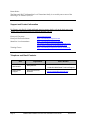
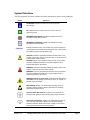

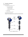

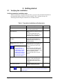
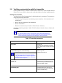
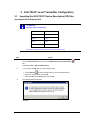
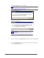
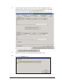
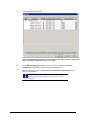
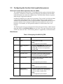
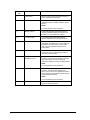
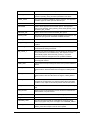
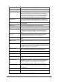
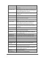

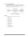
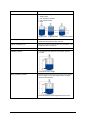
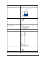
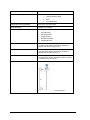
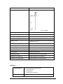
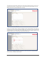
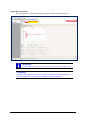
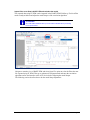
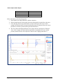
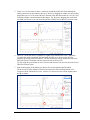
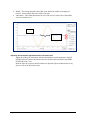
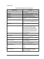
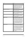
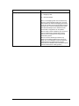
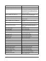
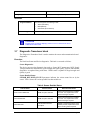
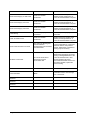
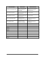

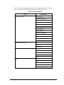
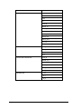
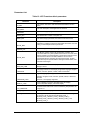
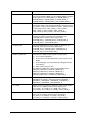
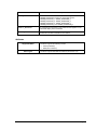
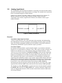
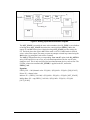
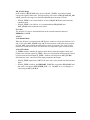
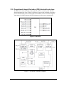
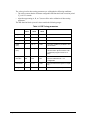
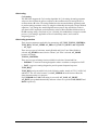
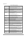
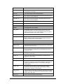
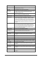
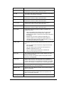
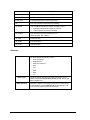
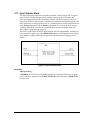
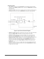
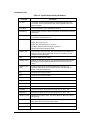
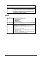
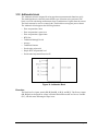
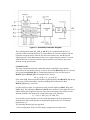
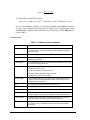
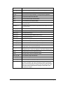
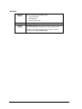
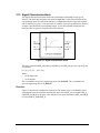
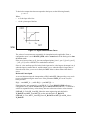
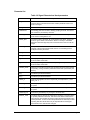
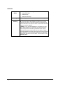
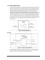
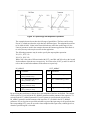
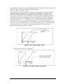
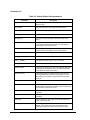
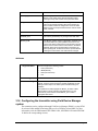
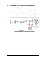
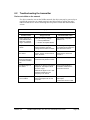
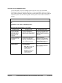
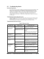
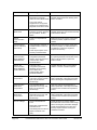
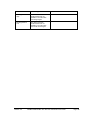
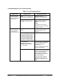
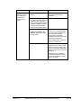
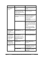
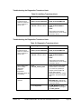
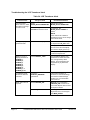
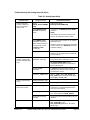
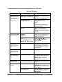
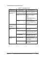
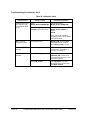
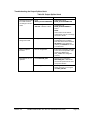
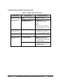
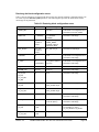
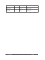
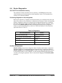
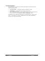
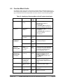
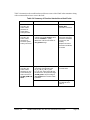
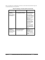
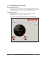
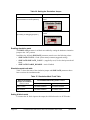
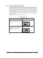


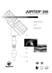
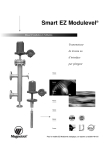
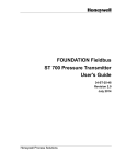


![[输入书名] - Emerson Network Power](http://vs1.manualzilla.com/store/data/005842917_1-6ec1a88a77b6fa212b87a12729f502af-150x150.png)