1
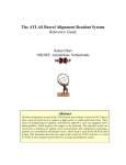
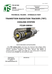
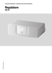
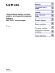
v1.0
August 2014
IBL-CO2 DCS
1. Introduction.
The Insertable B-Layer (IBL) of the ATLAS Pixel detector is cooled by liquid CO2. The liquid CO2 is provided
by two cooling plants (called A and B), each one capable to cool the IBL. Two plants guarantee a certain
redundancy. Each plant is controlled by a PLC, which is connected to the LHC technical network. In order to
implement a control system to be integrated into the Pixel-FSM as used in the ATLAS Control Room (ACR), the
data has to be exchanged from the LHC technical network to the ATLAS network. Two mechanisms are used:
DIP and MODbus. DIP for the majority of the data and MODbus (which is regarded as more reliable) for the
critical data. In USA15 a WinCC project is dedicated for this purpose and also to facilitate the FSM-part.
The main source of information which was used to implement it, is the EDMS document (nr. 1233464):
“SPECIFICATION OF CONTROL INTERFACE BETWEEN COOLING CONTROL AND ATLAS DCS”
Rev. No 11, 16 July 2014, by Lukasz Zwalinski et al.
2. Global Information
The Linux PC used:
WinCC project:
•
pcatlpixlcs20
ATLPIXIBLCO2 (id #330)
DIP
The DIP variables are available on a WinCC project called: ATLGCSIS2 (id #212)
This project, maintained by the central DCS team, obtains its data by means of the DIP protocol. It is quite
simple to read , by means of dpGet, the variables. For this purpose the following line had to be added to the
config file:
[dist]
distPeer = "pcatlgcsis2.cern.ch" 212
•
MODbus
The MODbus variables (in total 11 for both plants) are obtained by two MODbus drivers, one for each plant.
The concerned data-points have a dedicated _address_config. A common polling group takes care of a regular
readout. It is assumed that the MODbus readout is more reliable and that in case of a mismatch between a DIP
value or a MODbus value, the latter prevails.
1
v1.0
August 2014
3. WinCC ATLPIXIBLCO2 project
The console of the ATLPIXIBLCO2 WinCC project is shown in figure 1.
Figure 1: Console ATLPIXIBLCO2
NB: Be aware that more WinCC projects run on pcatlpixlcs20. Make sure you select ATLPIXIBLCO2!
The following managers are important for the project:
1.
CO2_Reader.ctl
A WinCC control script with argument [–num 20]. Its start mode is set to always. The main task of this
manager is to obtain at regular intervals the DIP-variables of ATLGCSIS2. The current interval time is 30
seconds.
2
v1.0
August 2014
2.
CO2_Watchdog.ctl
A WinCC control script with argument [-num 21]. Its start mode is set to always. This manager has several
tasks:
- Determine at regular intervals (currently every 30 seconds), based on the DIP and MODbus variables,
the state and status of the plants, vacuum, DIP and MODbus connectivity. An overall state and status of
the IBL-CO2 is determined as well.
- Check at regular intervals (currently every 5 minutes) the existence of the _address_configs of the
MODbus variables.
- Decode the MODbus ‘status_register’ variable and update the corresponding (boolean) data-point
variables.
- Increment every 2 seconds the DCS-watchdog MODbus variable by one. It acts as a heartbeat for the
plants.
3.
Modbus driver #2
A driver with argument [-num 2] and start mode set to always. This driver is meant for plant A.
4.
Modbus driver #3
A driver with argument [-num 3] and start mode set to always. This driver is meant for plant B.
The Modbus drivers make use of a common poll-group (type: _PollGroup, data-point: _Poll_IBLCO2)
with a readout frequency of currently 10 seconds.
3
v1.0
August 2014
4. User Manual
As long as the final FSM for the ACR is not ready, an alternative way to monitor the IBL-CO2 is necessary.
Therefore it is necessary to logon pcatlpixlcs20. The project supports only 2 commands:
1.
2.
Adjust user temperature setpoint (⁰C), equal to both plants.
Swap plant.
Execute the following command: WCCOAui –proj ATLPIXIBLCO2 –p CO2_VarModbus.pnl&
As a result a panel will appear as shown in figure 2.
Figure 2: IBL-CO2 MODbus variables
The MODbus variables could be read/write (DIP in our project is read-only). So, only by MODbus it is possible
to issue a command. In figure 2 there are 6 read variables (3 for each plant):
-
The read back value of the user temperature setpoint
The read back value of the accumulator saturation temperature
The status register: of which the individual variables are split into the Status-Register-Frame
on the right side of figure 2. Some remarks:
o The decomposition of the status register into the individual booleans is one of the tasks of the
CO2_Watchdog script.
o The swap request bit (and command) is only known to plant A.
o The names on the left are used as names for the data-points. On the right as they are used in the
document.
o The Start, Temporary Stop and Full Stop are the names of the interlocks.
4
v1.0
o
August 2014
If the Invalid button is pressed, the background color of the read variables will turn
yellow. Within 10 seconds they turn white again, indicating the _PollGroup and Modbus
drivers are running.
The write variables should be handled with care. Use (if needed) only the ACR/Fsm user temp. setpoint and
Swap button! The user setpoint is written to both plant A and plant B. If a value is entered a confirmation is
needed (Yes or No). The Swap button is only enabled if one of the plants is in state OPERATION and the other
in STANDBY. Otherwise it is not possible to swap. The swap command has to be acknowledged (Yes or No) as
well.
Note: The write variable DCS-watchdog will be incremented by 1 every 2 seconds (another task of the
CO2_Watchdog script).
To get a general overview of the IBL-CO2, execute the following command:
WCCOAui –proj ATLPIXIBLCO2 –p CO2_Fsm.pnl&
It will result in a panel as shown in figure 3.
Figure 3: General overview of the IBL-CO2
5
v1.0
August 2014
Very important is the first line of the panel containing the word IBL-CO2. Its background has to be green (ok).
Otherwise (yellow → orange → red) one of the 2 scripts (CO2_Reader or CO2_Watchdog) are not running
anymore. This is a serious matter. All the data will be undefined.
As mentioned before the CO2_Watchdog script takes care of the state and status of the different sub-systems, as
presented in the upper left corner: IBL-CO2 (the overall), Plant A, Plant B and Vacuum. These states go to
UNDEFINED if the connectivity to the DIP or MODbus variables are down. In the lower left corner the
connectivity is shown.
The other variables are combined into logical groups.
-
Main parameters: these variables (together with the interlock variables) determine the state of the plant.
The variables come from 2 sources: DIP and MODbus. In case of inequality the MODbus value prevails.
Additional parameters
Interlock Status: like the main parameters based on 2 sources (DIP and MODbus). The MODbus variable
prevails.
Alarms
UX15 Junction Box
Vacuum
5. State and Status
The main task of the CO2_Watchdog script is to determine the state and status of the plants. For these plants the
following states and status have been defined:
STATE:
STATUS:
OPERATION, NOT_READY, STOPPED, STANDBY, BAKEOUT, MAINTENANCE,
TRIPPED, UNKNOWN
OK, WARNING, ERROR, FATAL
For the state of a plant the following recipe is used:
if (connectivity == false)
state = UNKNOWN;
else if (cooling_ready == true)
state = OPERATION;
else if (cooling_running == true && operation_mode == Operation)
state = NOT_READY;
else if (cooling_running == false && interlock == false)
state = STOPPED;
else if (cooling_running == true && operation_mode == Standby &&
state_step == Standby)
state = STANDBY;
else if (interlock == true)
state = TRIPPED;
else if (operation_mode == Bakeout)
state = BAKEOUT;
else if (operation_mode == Maintenance)
state = MAINTENANCE;
else
state = UNKNOWN;
6
v1.0
August 2014
And for the status:
if (state == UNKNOWN)
status = FATAL;
else if (interlock == true)
status = ERROR;
else if (alarm == true)
status = WARNING;
else
status = OK;
NB: It is impossible that both plants are in state OPERATION (i.e. cooling_ready == true). The variable
cooling_ready (also known as Allow_DET) cannot be set true at the same time on both plants! The hardware
prevents it.
The overall state and status of the IBL_CO2 based on the state and status of the plants is determined by the
following recipe:
-
If one of the plants is in state OPERATION, then the overall state is OPERATION. The overall status is
taken over by the status of the plant in OPERATION.
Else the overall state is STOPPED and the least severe status of one of the plants is taken to be the overall
status.
The vacuum state has no influence on the overall state.
The vacuum status however, has to be combined with the overall status up to now. Take the most severe of the 2
and that one will be the overall status.
The ATLAS FSM tree does not know about OPERATION, TRIPPED, etc. For the FSM representation the IBLCO2 node knows only 3 of the ATLAS supported states: READY, NOT_READY and UNKNOWN. The
following translation is used from IBL-CO2 overall state to ATLAS-FSM node:
if (state == OPERATION)
fsmState = READY;
else if (state == NOT_READY, STOPPED, STANDBY, BAKEOUT, MAINTENANCE or TRIPPED)
fsmState = NOT_READY;
else
fsmState = UNKNOWN;
The fsmStatus is copied (without translation) from the overall status.
7
v1.0
August 2014
6. FSM
It is foreseen that the panel, as show in figure 3, will be used for the FSM screen. Up to now (August 2014) the
full implementation is not available yet. However, a first attempt of the FSM-node is ready. See figure 4. The
states are propagated successful, however there is still something wrong with the status.
Another item what is missing, is the alarm handling for the alarm screen. Everything is expected to be ready
before the end of September 2014.
Figure 4: FSM PIX-IBL-CO2
8