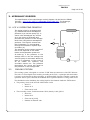
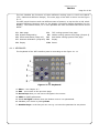
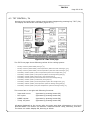
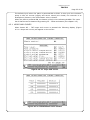
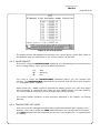
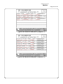
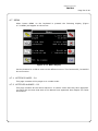
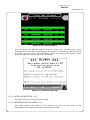
1
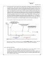
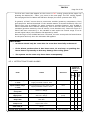
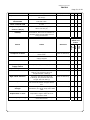
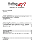
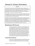
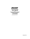
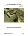
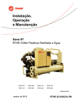
Date: 3/29/2007
TS-CV-DC
EDMS Document No
781354
CERN
CH-1211 Geneva 23
Switzerland
. TS/CV Detector Cooling Project Document No.
186.15.40
TECHNICAL FOLDER – HYDRAULIC PART
TRANSITION RADIATION TRACKER (TRT)
COOLING SYSTEM
FCUM-00004
General description and functionalities
This TRT cooling plant cools down the electrical high-voltage cables
entering the Atlas experiment sub-detectors, mainly to inner detector. In
nominal operating conditions the plant delivers 24 m3/h of
perfluorocarbon C6F14 at 14°C and 8 bar (a). The cooling plant is expected
to remove some 70 kW from the electrical cables.
Prepared by :
Jani Lehtinen
TS/CV
[email protected]
Checked by :
EDMS Document No
781354
Page 2 of 48
History of Changes
Rev. No.
Date
Pages
Description of Changes
EDMS Document No
781354
Page 3 of 48
HISTORY OF CHANGES
1.
INTRODUCTION __________________________________________________________ 5
1.1
2.
Related documentation __________________________________________________________ 5
NAMING & SPARE PARTS _________________________________________________ 6
2.1
MP5 naming ___________________________________________________________________ 6
2.2
General naming _______________________________________________________________ 11
2.3
Naming of the piping ___________________________________________________________ 12
2.4
Spare part list _________________________________________________________________ 12
3.
HYDRAULIC DOSSIER ___________________________________________________ 14
3.1
LCS v.2 operating principle _____________________________________________________ 14
3.2
Cooling station ________________________________________________________________ 14
3.3
Sub-detector __________________________________________________________________ 15
3.4
C6F14 _______________________________________________________________________ 16
3.4.1
3.4.2
Properties of C6F14 ________________________________________________________________ 16
Compatibility of C6F14 with materials _________________________________________________ 18
3.5
Cooling plant drawings _________________________________________________________ 19
3.6
Civil engineering integration_____________________________________________________ 19
4.
USER MANUAL __________________________________________________________ 20
4.1
4.1.1
4.2
4.2.1
4.2.2
4.2.3
4.2.4
4.3
4.3.1
4.3.2
4.3.3
4.3.4
4.4
4.4.1
4.4.2
4.5
4.5.1
Introduction __________________________________________________________________ 20
Keyboard_________________________________________________________________________ 21
TRT control / F4_______________________________________________________________ 22
Loops and curves __________________________________________________________________
PPV cycles _______________________________________________________________________
MODE request ____________________________________________________________________
Temperature set-point _______________________________________________________________
23
24
25
25
Cooling settings _______________________________________________________________ 26
Starting cooling____________________________________________________________________
cooling settings ____________________________________________________________________
Monitoring of parameters ____________________________________________________________
Stop procedure ____________________________________________________________________
26
26
27
27
The “LEAKLESS” protection ___________________________________________________ 27
liquid leakage _____________________________________________________________________ 27
Air infiltration _____________________________________________________________________ 28
Faults and Alarms - F5 _________________________________________________________ 29
Liste of Faults and Alarms ___________________________________________________________ 30
4.6
Sensors calibration – F7 ________________________________________________________ 32
4.7
Menu ________________________________________________________________________ 34
4.7.1
4.7.2
4.7.3
4.7.4
4.7.5
4.7.6
4.7.7
4.7.8
Liste des pages – R1 ________________________________________________________________
Liste des alarmes – R2 ______________________________________________________________
Liste des recettes – R3 ______________________________________________________________
historique des alarmes – R4 __________________________________________________________
Liste des formulaires – R5 ___________________________________________________________
Arret de l’impression – R6 ___________________________________________________________
Mot de passe – R7__________________________________________________________________
Esc – R8 _________________________________________________________________________
34
34
35
35
36
36
36
36
EDMS Document No
781354
Page 4 of 48
4.8
5.
Time and date_________________________________________________________________ 37
COMPONENT DOCUMENTATION _________________________________________ 38
5.1
Component data _______________________________________________________________ 38
5.1.1
5.1.2
5.1.3
5.1.4
5.1.5
5.1.6
5.1.7
5.1.8
5.1.9
5.1.10
5.1.11
5.1.12
5.1.13
5.1.14
5.1.15
5.1.16
5.1.17
5.1.18
5.1.19
5.1.20
5.1.21
5.1.22
5.1.23
5.1.24
5.2
6.
Balancing valve (BAV)______________________________________________________________
Butterfly valve (CBV)_______________________________________________________________
Converter Electropneumatic (CEP) ____________________________________________________
Chemical filter (CF) ________________________________________________________________
Differential pressure regulator (DPR)___________________________________________________
Electrovalve 2 ways (EVB) __________________________________________________________
Sight flow glass (FSG) ______________________________________________________________
Flow meter (FZA)__________________________________________________________________
Heater (HEA) _____________________________________________________________________
Heat Plate Exchanger / Chilled water (HPX) _____________________________________________
Mecanical filter (MF1) ______________________________________________________________
Pneumatic control valve 2 ways (PCVA1) _______________________________________________
Manometer (PG) ___________________________________________________________________
Pressure regulator (PR) ______________________________________________________________
Pressure switch (PST2) ______________________________________________________________
Pressure Transmitter (PT) ____________________________________________________________
Pneumatic valve 2 ways (PVA) _______________________________________________________
Relief valve (REV) _________________________________________________________________
Strainer (STR)_____________________________________________________________________
Storage tank (STT) _________________________________________________________________
Temperature Transmitter (TT) ________________________________________________________
horizontal centrifugal pump (vcp)______________________________________________________
Vacuum pump (VP) ________________________________________________________________
liquid level tranmitter (WLT) _________________________________________________________
38
38
38
38
38
38
38
38
38
39
39
39
39
39
39
39
40
40
40
40
40
40
40
40
Photo gallery__________________________________________________________________ 41
REGULATION PARAMETERS _____________________________________________ 45
6.1
Regulation of pressure in reservoir:_______________________________________________ 45
6.2
Regulation of temperature ______________________________________________________ 45
6.3
Regulation of secondary circuit water pressure (station)______________________________ 45
6.4
Regulation of water conductivity _________________________________________________ 45
6.5
Regulation of secondary circuit water pressure (24 loops) ____________________________ 45
7.
TEST ___________________________________________________________________ 46
7.1
Hydraulic performance _________________________________________________________ 46
7.2
Cooling performance ___________________________________________________________ 46
7.3
Leaktightness test______________________________________________________________ 46
7.4
Pressure test __________________________________________________________________ 46
8.
PREVENTIVE MAINTENANCE ____________________________________________ 47
9.
CONTACT PERSONS _____________________________________________________ 48
ANNEX A – Drawings
ANNEX B – Component Manuals
ANNEX C – Demande Achat Interne (DAI)
ANNEX D – Pressure test report
EDMS Document No
781354
Page 5 of 48
1. INTRODUCTION
Plant Name: MP5 name - FCUM-00004
(TS/CV/DC project number 186/15/40)
Location: ATLAS Experimental cavern UX15
Design responsible: Carsten Houd,
TS/CV/DC, tel. 70679
The ATLAS Inner detector (ID) is composed of 3 different particle detectors: The
Transition Radiation Tracker (TRT), the Semi-Conductor Tracker (SCT) and Pixel
detector. The Inner Detector is placed inside the Liquid Argon Barrel Cryostat.
The cooling system of the Transition Radiation Tracker (TRT) is a monophase cooling
system. The TRT cooling system is using a C6F14 perfluorocarbon as a coolant in
order to prevent any damage in case of leak inside the detector.
The cooling system consists of the cooling plant (in UX15 level 0 corner of US- and Cside), control rack FCTIR00015 (USA15 CV-room), electro pneumatic rack FCTIR00020
(USA15 CV-room) and liquid analyses and vacuum pumps rack FCTIR00021 (USA15
CV-room).
The cooling plant consists of a 1.5 m3 reservoir large enough to contain all the C6F14
in the installation, a pump, and a heat exchanger connected to the TS/CV chilled water
network. The system comprises 4 main circuits going to the distribution racks on HSstructures on the USA- and US-sides supplying the coolant to 200 circuits to the
detector. The inlet pressure is constant to all four main lines, and the flow rate is
regulated by manual balancing valves.
The station also comprises an emergency heater system of 45 kW designed to protect
the installation in case of a vacuum failure on the liquid argon cryostat. Such a failure
would expose the liquid to a temperature of 90 °K.
1.1 RELATED DOCUMENTATION
Functional analysis of the TRT cooling system can be found from EDMS 596315 v.1
Functional Analyses for TRT, Cables & Vacuum pumps cooling system.
Date: 3/29/2007
TS-CV-DC
CERN
CH-1211 Geneva 23
Switzerland
2. NAMING & SPARE PARTS
2.1 MP5 NAMING
EDMS Document No
781354
. TS/CV Detector Cooling Project Document No.
186.15.40
EDMS Document No
781354
Page 7 of 48
EDMS Document No
781354
Page 8 of 48
EDMS Document No
781354
Page 9 of 48
EDMS Document No
781354
Page 10 of 48
EDMS Document No
781354
Page 11 of 48
2.2 GENERAL NAMING
Components
ACH
BAV
BOV
BPR
BTV
BUF
CBV
CEP
CF
CHV
CIR
COP
CSC
DPR
ECVA
ECVB
EI
EVA
EVB
FRA
FSG
FZA
GFL
HCP
HEA
HPX
LFL
MCVA
MCVB
MDP
MF
MVA
MVB
PCVA
PCVB
PG
PR
PT
PVA
PVB
PZA
QT
REV
RFB
RFC
STR
STT
TA
TT
TVA
TVB
VCP
VP
WLT
Air cooled water chiller
Balancing valve
Booster
Back pressure regulator
Butterfly valve
Buffer tank
Compact ball valve
Converter E->P
Chemical filter
Check valve
Circulator
Piston compresor
Control scale
Differential pressure regulator
Electrical control valve 2 ways
Electrical control valve 3 ways
Switch control (manual valve)
Electrovalve 2 ways
Electrovalve 3 ways
Frame
Flow sight glass
Flow controller
Gas flowmeter
Horizontal centrifugal pump
Resistance heater
Heat plate exchanger
Liquid flowmeter
Manual control valve 2 ways
Manual control valve 3 ways
Magnetic drive centrifugal pump
Mechanical filter
Manual valve 2 ways
Manual valve 2 ways
Pneumatic control valve 2 ways
Pneumatic control valve 3 ways
Pressure gauge
Pressure regulator
Pressure transmitter
Pneumatic valve 2 ways
Pneumatic valve 3 ways
Pressure switch
Conductivity transmitter
Relief valve
Resin filter body
Resin filter cartridge
Strainer
Storage tank
Temperature controller / alarm
Temperature transmitter
Thermostatic valve 2 ways
Thermostatic valve 3 ways
Vertical centrifugal pump
Vacuum pump
Water level transmitter
Lines
AL
CWL
DL
DGL
DLL
DWL
GL
IGL
ILL
LL
MGL
MLL
MWL
PL
PWL
VL
Analog signal line
Chilled water line
Digital line
Distribution gas/vapor line
Distribution liquid line
Demineralized water line
Gas line
Intermediate gas/vapor line
Intermediate liquid line
Liquid line
Main gas/vapor line
Main liquid line
Mixed water line
Pneumatic line
Power line
Vacuum line
EDMS Document No
781354
Page 12 of 48
2.3 NAMING OF THE PIPING
2.4 SPARE PART LIST
EDMS Document No
781354
Page 13 of 48
EDMS Document No
781354
Page 14 of 48
3. HYDRAULIC DOSSIER
The specification of the Liquid argon cooling system can be found in EDMS
391190 – ATC-TL-EP_0002 v.2 COOLING PLANT FOR TRT. The drawings,
purchase orders and component manuals can be found in Annexes.
3.1 LCS V.2 OPERATING PRINCIPLE
The liquid is held in a storage tank
(3) maintained below atmospheric
pressure by a vacuum pump (2). A
check valve discharges any excess
air in the event of drainage and
prevents the pressure in the storage
tank from rising above atmospheric
pressure. The liquid is moved into
the exchangers (1) incorporated
through the electronic system by a
circulator (4).
The pressure at the various points of
the circuit depends on the head
losses and hydrostatic pressures.
At start-up, if the pressure in the
storage tank is not low enough the
vacuum pump is activated. While the
later is in operation, in the event of
an air intake for instance, the
circulator cannot run. The pressure
throughout the circuit still equal to
the pressure in the storage tank.
3.2
1
2
5
3
4
Fig.1
COOLING STATION
This cooling system is designed to evacuate 70 kW from the electronics of the TRT detector.
The unit is a closed liquid circuit working according to the LCS v.2 principle and connected to
a primary circuit through an heat exchanger. A Programmable Logical Controller controls the
operation. Due to space constraint the manifold unit is separated from the cooling station itself
The distribution racks distributes the cooling liquid to 200 channels inside the TRT detector.
• The primary circuit is the ATLAS chilled water circuit
o Inlet 5°C
o Return 11°C
o Flow rate 10 m3/h
• The secondary circuit : Perfluorocarbon C6F14 (density 1.688 @20°C)
o Inlet 14°C
o Return 20°C
o Flow rate 24 [m3/h]
o Number of channels: 200
EDMS Document No
781354
Page 15 of 48
A circulator pump moves the fluid from a pressurized storage tank to the exchangers through a
brazed plates heat exchanger connected to the primary circuit via a pneumatic 2 ways valve.
The temperature is controled by a PID module inside the PLC. The circuit supply pressure is
regulated by a back pressure regulation valve on a by-pass.
• Pump specifications:
o Horizontal magnetic drive centrifugal pump
o Flow max : 24 [m3/h] at head max 60[m].
o Power: 22 kW (comes directly from UX15)
( Maximum Head requirement: 1024 mbar in lines, 500 mbar in the station, 500 mbar in the
heat exchanger, 3300 mbar in height difference, 800 mbar inside detector + 20%)
• Back pressure regulator specifications:
o Stainless steel self-operated regulator
o Flow max : 24 [m3/h]
o Working temperature: 20°C
o Outlet pressure: 10 bar
o Differential pressure range: 10.5 bar (depending of the pump’s curve)
• Emergency heaters specifications:
o 3 x 12 kW + 1 x 9 kW thermo plungers in series
o Power consumption: 45 kW
The pressure of the storage tank is controlled by a membrane vacuum pump and a pressure
transmitter.
Storage tank capacity: 1. 5 [m3]
The cooling station and the manifold are stainless steel material as all the piping is realized
with multi-layer PE/Alu/PE pipe and crimp fitting.
3.3
SUB-DETECTOR
Power and flow rate (ΔT = 6)
Rack platform 1 Rack platform 7
US side
US side
Flow
Power Flow
Power
[m3/h] [kW]
[m3/h] [kW]
Barrel
1.36
4
1.36
4
Straw A,
0.82
2.4
0.82
2.4
B, C
Wheel A
1.63
4.8
1.63
4.8
Wheel B
1.22
3.6
1.22
3.6
Wheel C
0.82
2.4
0.82
2.4
Total
5.85
17.2
5.85
17.2
(the 4 distribution racks are identical)
Rack platform 1
USA side
Flow
Power
[m3/h] [kW]
1.36
4
0.82
2.4
1.63
1.22
0.82
5.85
4.8
3.6
2.4
17.2
Rack platform 7
Total
USA side
Flow
Power Flow
Power
[m3/h] [kW]
[m3/h] [kW]
1.36
4
5.44
16
0.82
2.4
3.27
9.6
1.63
1.22
0.82
5.85
4.8
3.6
2.4
17.2
6.53
4.90
3.27
23.40
19.2
14.4
9.6
68.8
EDMS Document No
781354
Page 16 of 48
Flow per
line [l/h]
Per rack
Number and Ø
Flow [l/h]
[mm]
8 X Ø 11/12
1360
24 X Ø 7/8
1360
8 X Ø 7/8
816
6 X Ø 11/12
1633
8 X Ø 11/12
1224
4 X Ø 11/12
816
Total
Number
Flow [l/h]
Inlet
170
32 X Ø 11/12
5440
Return
57.7
96 X Ø 7/8
5440
Straw A, B, C
102
32 X Ø 7/8
3265
Wheel A
272
24 X Ø 11/12
6530
Wheel B
153
24 X Ø 11/12
4898
Wheel C
204
16 X Ø 11/12
3265
Total
23400
(Each distribution rack is splitted in 2 parts: Inlet with 34 channels and Return with 50 channels
due to the modularity of the barrel: 3 return lines for 1 inlet line)
Barrel
3.4
C6F14
3.4.1 PROPERTIES OF C6F14
To avoid the catastrophic consequences of a water leak inside the ATLAS Tracker fluorocarbon
C6F14 has been chosen as a safe coolant for the TRT detector.
Fluorocarbons are a family of compounds containing carbon and fluorine only. Contrary to some
classical refrigerants (HCFC or HFC) they do not contain Hydrogen. Under ionizing radiation HF
acid may be formed so any H donor impurity (ex. Water) must be absent.
Advantages of fluorocarbons:
o High dielectric strength
o Good chemical stability under ionizing radiation
o Low toxicity and low corrosiveness
o Non-flammable
o Zero ozone-depletion potential – ODP
o Low global warming potential – GWP
Fluorocarbon
PF5060
(FC72)
Chem.formula
C6F14
Mean Mol.Wt.
338
Boiling point @1 atm [°C]
56
Dens.[g/cm3]
1.68 @25°C
-3
Liquid DynamicViscosity [10
Pa.s]
0.67 @25°C
Liquid Kinematic Viscosity [10-6 m2/s]
0.4 @ 25°C
1.9 @-54°C
Surface Tens.[dy/cm]
12.0 @25°C
Vapour press.@-10°C [Torr]
[bara]
58
0.077
Latent Heat Vap. [J/mole]
[kJ/kg]
29670
88
Specific Heat [kJ/kg.K]
1.05
Thermal conductivity [W/m.K]
0.057
EDMS Document No
781354
Page 17 of 48
Liquid-Gas Expansion Fact
@ -10°C
~1500
C6F14 (FC72) Saturation curve
2000
1900
log10(P) = 9.729 -1562/T
1800
1700
1600
1500
1400
1300
1100
1000
900
800
700
600
500
400
300
200
100
0
-20 -15 -10 -5
0
5
10 15 20 25 30 35 40 45 50 55 60 65 70 75 80
Tsat (C)
Psat (mbar.a)
1200
EDMS Document No
781354
Page 18 of 48
3.4.2 COMPATIBILITY OF C6F14 WITH MATERIALS
Note: one should avoid plastics with the fluorocarbons as they take out the plastiziser and the product
becomes brittle. Source: G. Lenzem, DELPHI RICH and 3M
M. Capeans, Nov.2001
EDMS Document No
781354
Page 19 of 48
C6F14 - O-rings
EPDM
Perbunan (NBR)
or caoutchouc or nitrile rubber
Suggested by
3M as best
choices
Neoprene
Butyl rubber
PVDF
Kalrez
Viton
Teflon (PTFE & PCTFE)
Rad Hard
Compatibility
< 108 rad
(Data: CERN 82-10)
108 rad
(Data: CERN 82-10)
107 rad
(Data: CERN 82-10)
< 105 rad
(Data: CERN 82-10)
108 rad
(Data: Angst+Pfister)
106 rad
(Data: CERN 82-10
< 107 rad
(Data: CERN 82-10)
BAD
OK
(Data: 3M)
OK (but some effect)
(Data: 3M)
OK
(Data: 3M)
OK
(Data: 3M)
OK (but some effect)
(Data: 3M)
BAD
(Data: 3M)
BAD
GLOBAL
RESULT
OK
OK
OK
BAD
OK
BAD
*
BAD
* Viton O-rings were used in DELPHI with no leak problems. Source: G. Lenzem, DELPHI RICH
3.5 COOLING PLANT DRAWINGS
3.6 CIVIL ENGINEERING INTEGRATION
See drawings in CDD:
-
Civil Engineering - Package 1 - Underground
o
Civil Engineering – UX15
The services required by this cooling plant are:
•
10 m3/h of chilled water
•
67 kW, 400V from the standard power distribution
•
850 W, 220V from the UPS power distribution
•
Compressed air at 6bar (consumption is negligible).
•
TCP/IP connection(s)
EDMS Document No
781354
Page 20 of 48
4. USER MANUAL
4.1 INTRODUCTION
This user manual concerns the use of the PLC interface panel on the control rack
FCTIR-00015. The normal operation of the TRT cooling plant is done via PVSS logistic
situated in CERN Experimental Control Room (ECR). The XBT panel can be operated
only when being authorized from the PVSS logistic.
Figure 4.1.1 XBT-Magelis Interface Panel
EDMS Document No
781354
Page 21 of 48
The PLC handles the functions of three different cooling units in UX15 and USA15
(TRT, Cables and Diffusion Pumps). The main page of the XBT is shown on the Figure
4.1.1.
The XBT panel functions with two different sets of buttons, on top the R1 to R8, which
operates different functions seen on the display (functions change depending on the
display). The buttons below, F1 to F10 operates the main functions that can be found
below.
F1 Main page
F2
F3 System designed by
F4
F5 Faults and status (Chap.4.5)
F6
TRT cooling system front page
Cables cooling system front page (Chap.4.2)
Rod Racks cooling system front page
F7 Sensors calibration (Chap.4.6) F8
Empty
F9 Empty
Reset
F10
4.1.1 KEYBOARD
The keyboard of the XBT interface panel is according to the figure 4.1.1.1
Figure 4.1.1.1 Keyboardl
1: Menu – see chapter 4.7
2: ESC – move back to the previous page
3: Arrow keys that you can use to navigate in the menus
4: MOD to modify parameter
5: Small led lights indicate when the button next to it is operational
6: Validate your choice by hitting Enter
7: Number keys 0 to 9 that you can use e.g. to insert the password or set points.
EDMS Document No
781354
Page 22 of 48
4.2 TRT CONTROL / F4
Access to the Liquid Argon cooling control system happens by pressing key “TRT” (F4).
The display will show the view below (figure 4.2.1).
Figure 4.2.1 TRT front page
The TRT front page shows following values of the cooling system:
-
Primary network (chilled water) flow [m3/h]
-
Primary network (chilled water) inlet temperature (before the heat exchanger) [°C]
-
Primary network (chilled water) outlet temperature (after the heat exchanger) [°C]
-
Secondary network (C6F14) return temperature (before the storage tank) [°C]
-
Secondary network (C6F14) inlet pressure (before the storage tank) [bar(a)]
-
Secondary network (C6F14) tank level in the storage tank [l]
-
Secondary network (C6F14) memorized tank level in the storage tank [l]
-
Secondary network (C6F14) conductivity level [uS/cm]
-
Secondary network (C6F14) outlet temperature (after the storage tank) [°C]
-
Secondary network (C6F14) outlet pressure (after the storage tank) [bar(a)]
-
Secondary network (C6F14) set-point temperature (after the storage tank) [°C]
The screen has on its right side following functions:
-
loops and curves
(operates by pressing button R2)
-
PPV cycles
(operates by pressing button R4)
-
MODE request
(operates by pressing button R6)
-
Temp. set point
(operates by pressing button R8)
All pages displayed on the screen after the main page bear information on the Cycle
and the Status. The former can assume 3 different values: Stop, Stand-by, and Run.
The latter can either display OK, Warning or Alarm.
EDMS Document No
781354
Page 23 of 48
The default Cycle when the plant is powered ON is STOP. In this cycle the circulator
pump is idle; all circuits (supply and return valves) are closed; the reservoir is at
atmospheric pressure; the chilled water valve is closed.
When the plant is powered ON, the Status is likely to be indicating ALARM. The exact
list of alarms can be obtained by pressing F5 – faults and status (see chapter 4.5).
4.2.1 LOOPS AND CURVES
When button R2 – TRT loops and curves is pressed the following display (Figure
4.2.1.1.loops and curves) will appear on the screen.
Figure 4.2.1.1 loops and curves
Figure 4.2.1.2 Distribution racks control
EDMS Document No
781354
Page 24 of 48
Press the button R8 to have the access on the screen. There will be a rectangular box
appearing where the number of the wanted loop or curve is to be written (next to the
text ‘Go to page’). Insert the number using the number keys, and press enter.
The loops and curves display allows the access to the 24 different cooling loops of the
cooling system (see chapter 3 and the drawings Annex A). The PLC shows the
pressure of the cooling loop during the last 24 hours which can be seen on the display.
There is also access to the different measuring points of the cooling station (curves 25
to 32 according the figure 4.2.1.1). Below you have two examples, Figure 4.2.1.2 TRT
loop 01, and Figure 4.2.1.3 TRT – Tank level.
The curves and loops can be viewed without a password. In order to change the
settings of the curves and loops you need to insert the USER password. The USER
password can be inserted from the menu (see chapters 4.1.1.keyboard and
4.7.MENU).
For more detail on the loops control see chapter 4.3. COOLING SETTINGS.
Figure 4.2.1.3 TRT – Tank level
4.2.2 PPV CYCLES
When button R4 – PPV cycles is pressed the following display (Figure 4.2.2.1 PPV
cycles) will appear on the screen.
EDMS Document No
781354
Page 25 of 48
Figure 4.2.2.1 PVV cycles
The display shows the elapsed time between the vacuum pump cycles. Here some of
the possible leaks (air infiltration) in the cooling system can be seen.
4.2.3 MODE REQUEST
From here, using the MAINTENANCE password, you can manage the current function
of the cooling station. There are three different functions.
1)
Stop
2)
Stand-by
3)
Run
You need to insert the MAINTENANCE password before you can operate this
function. The MAINTENANCE password can be inserted from the menu (see chapters
4.1.1.keyboard and 4.7.MENU).
When button R6 – MODE request is pressed the display (Figure 4.2.1.TRT front page)
will not change. A rectangular box below the text ‘MODE request’ will start plinking.
The cooling station mode can now be changed using the arrow keys.
The cooling station operation is more precisely described in the chapter 4.3.Cooling
Settings.
4.2.4 TEMPERATURE SET-POINT
From here you can manage the outlet cooling liquid temperature that is going to the
detector. You need to insert the USER password before you can operate this function.
The USER password can be inserted from the menu (see chapters 4.1.1.keyboard and
4.7.MENU).
EDMS Document No
781354
Page 26 of 48
When button R8 – ‘Temp. setpoint’ is pressed the display (Figure 4.2.1.TRT front
page) will not change. A rectangular box below the text ‘Temp.setpoint’ will start
plinking. Now you can change the temperature set point using the number keys.
The temperatures can be set between 16 and 20 degrees. The cooling system
operates with one uniform temperature. If you change the temperature of one of the
cooling loops, you will change the temperature of all the cooling loops at the same
time.
4.3 COOLING SETTINGS
4.3.1 STARTING COOLING
The cooling mode can only be changed using MAINTENANCE password. The
MAINTENANCE password can be inserted from the menu (see chapters
4.1.1.keyboard and 4.7.MENU).
The cooling can only be started at the stand-by mode. If the system is stopped, you
need first to go in the stand-by mode from the TRT front page – mode request (See
chapter 4.2.3). Before starting the system you have to wait that the vacuum in the
storage tank is at 400 mbar (a).
Upon selecting the RUN Cycle, the circulator pump starts working and the chilled
water valve begins cooling the heat exchanger. This temperature regulation is piloted
by a PID control algorithm. The set points for these closed-loop controls are operated
according to the chapters 4.2.4 TEMPERATURE SET-POINT, and 4.2.1 LOOPS AND
CURVES.
If all the cooling circuits are closed or locked when the circulator pump starts working
(i.e. when the RUN Cycle is selected), the by-pass regulation valve shall divert the
flow from the supply manifold to the return manifold. Starting pumping through the
by-pass before opening any circuit is in fact the safest way to proceed, as it will
prevent any initial pressure or temperature spike to propagate to the detector.
4.3.2 COOLING SETTINGS
Given the correlation between flow rate and pressure (loosely ∆P~FlowRate2), the
user should turn his attention to the exact cooling circuits he plans to flow water
through. This is done by hitting the “Loops and curves” keys on the panel Chapter
4.2.1 LOOPS AND CURVES.
You need to insert the USER password before you can operate cooling settings. The
USER password can be inserted from the menu (see chapters 4.1.1. keyboard and
4.7. MENU).
The cooling loops have to be viewed separately. You can move from one loop to the
next one by pressing the key F8. With the USER password you can operate the
pressure set point of the loops, and the state of the loops.
Any given cooling loop can display one of three states:
EDMS Document No
781354
Page 27 of 48
•
Locked: supply and return valves are closed. This is the state you should
select only in case of major leak on the loop.
•
Open: supply and return valves are open.
•
Closed: supply valve is closed but return valve is open. Select this state if the
plant is in Stand-by and you intend to open the circuit once the plant is in
Run (the reason for this is explained in §5.3). This is also the state in which a
circuit should remain if it is piped to the detector and contains water left inside.
By letting the return valve open, the whole circuit will be kept below
atmospheric pressure and thereby prevent any liquid spill out through possible
leaks in the detector.
When a cooling circuit changes from locked to open, there is a 6 sec time delay
between the opening of the return and the supply valve. Similarly, when a open circuit
is to be locked, the return valve is shut 6 sec after the supply valve.
Note that when the cooling plant is in Stand-by, the pressure in the reservoir is kept
sub-atmospheric by a vacuum pump. This pressure is controlled by switching ON the
vacuum pump when the pressure surges 50mbar and OFF when it is back at its set
point. Therefore, when the volume of a cooling circuit is for the first time put in
contact with the reservoir volume, (example: locked
closed or locked
open), the
vacuum pump will have to remove that additional air from the reservoir.
4.3.3 MONITORING OF PARAMETERS
Real time information on the main parameters of the cooling plant can be viewed on
the TRT front page. The parameters of the 24 cooling loops to the detector can be
viewed at the loops and curves, chapter 4.2.1.
4.3.4 STOP PROCEDURE
The MAINTENANCE operator can select Stop from any of the other cycles. When
doing so, the circulator pump stops, the chilled water, the supply valves shut and the
return valves open. The negative pressure in the reservoir is no longer maintained.
The cooling plant can remain safely in Stand-by or
Stop and it should not be powered off.
4.4 THE “LEAKLESS” PROTECTION
When the cooling plant is in Stand-by, the whole system (plant + piping + detector) is
below atmospheric pressure whereas in Run, only the return pipes and eventually part
or the detector is in negative pressure. Therefore, should a leak occur, it may lead to
air infiltration.
Liquid leakage can happen only when the system is operated at run mode.
4.4.1 LIQUID LEAKAGE
A liquid leak can be detected and stopped early in time. This is done by continuously
measuring the liquid level in the reservoir and stopping the circulator pump when a
significant drop is detected. As soon as the pump stops, the sub-atmospheric pressure
prevails throughout the whole system (system = cooling plant + piping + detector),
thereby stopping the liquid spillage.
EDMS Document No
781354
Page 28 of 48
The liquid level in the reservoir may drop without necessarily meaning that liquid is
lost somewhere. This the case when the plant goes from Stand-by to Run and/or when
cooling(s) circuits are put into service (more liquid leaves the reservoir to fill-up new
volumes outside the plant) or when the pumped flow varies (altering the pressure set
point). It is quite often the case that air trapped inside the detector piping itself takes
time to be flushed down to the reservoir, so new volumes of liquid are still being filled
outside the plant, long after the pumping has started. These liquid level disturbances
(opening circuits, pump start/stop and change of flow throughout) are acknowledged
by the PLC and do not set off the Fast Liquid Level Change ALARM. However, after one
of these disturbances has occurred, the PLC needs to rememorize a new stable level.
The level is considered suitable to be memorized if it remains within a +- 5L margin of
a given level for the 15 minutes following the reading of that level. Once a new level is
memorized, the surveillance is reactivated and any level drop of more than 100L will
give rise to the Fast Liquid Level Change ALARM and take the system to Stand-by.
The evolution of liquid level during all these events is shown below:
Figure 4.4.1.1 Normal and abnormal variations of the liquid level in the reservoir
During the surveillance inhibition period, the Level stability Fault will appear (Faults &
Warnings page). Once the Level surveillance is back on, this fault will disappear.
4.4.2 AIR INFILTRATION
Air infiltration is not a problem but may become one if it is big enough. It may
equalize the pressure to atmospheric and thereby allow liquid to spill out.
In case of a major air infiltration causing the air pressure to rise above 0.9bar, the
Pressure Fault will appear in the Warnings page and the circulation pump stops (if the
plant happens to be in Run at that moment). When the pressure drops below 0.9bar
the circulation pumps restarts.
EDMS Document No
781354
Page 29 of 48
However, after 20 minutes of continuous vacuum pump working, the Vacuum pump
timing ALARM will make the system go to Stand-by (thus bringing the circulation
pump to a definitive halt). Note however that in Stand-by mode the reservoir pressure
regulation is still ON, so the vacuum pump carries on working to bring the pressure
down to the set point if possible.
4.5 FAULTS AND ALARMS - F5
By pressing F5 on the main page you can manage the faults and alarms of all three
the cooling systems. Alarms can be reset by pressing key F10.
Figure 4.5.1 Faults
Figure 4.5.2 Alarms
EDMS Document No
781354
Page 30 of 48
The first two views that appear on the screen is TRT cooling system faults pages. By
pressing the button R8 – ‘Next’, you move on the next page. The TRT cooling system
has two pages like ID Cables and Diffusion Pumps (the other systems after TRT).
In general, a FAULT occurs when a continuous variable (pressure, temperature, flow)
goes beyond a defined threshold. If the variable attains a second threshold, then the
FAULT turns into an ALARM. For some continuous variables however, only ALARM or
FAULT thresholds were defined. Obviously, this is also the case for binary (boolean)
variables (pressure switches, shut off valves, circuit breakers etc). Once the origin of a
FAULT has been corrected (i.e. the variable is back within its normal range or to its
normal logical value) the indication OK appears by itself.
Once the origin of an ALARM has been corrected, the user must push the Reset button
on the panel and only then the indication OK appears.
IMPORTANT:
•
An Alarm should only be reset after its cause has been fully understood.
•
If the Alarm persists after it has been reset, do not keep on pushing the
Reset button repeatedly as this may damage the cooling plant.
•
The system can be reset only three times consequently.
4.5.1 LISTE OF FAULTS AND ALARMS
Cycles in
which it is
active
Liquid outlet: Temp.
The temperature of the water at the
supply manifold is below 16ºC
none
●
The temperature of the water at the
supply manifold is above 24ºC
none
●
The pressure at the supply manifold is
below 1.2 bar(a).
none
●
Halts circulator
pump
●
High press.
The pressure at the supply manifold is
above 6.0 bar(a).
Chilled water:
temp<8ºC
The chilled water temperature is lower
than 8ºC.
none
●
●
●
Chilled water:
temp>17ºC
The chilled water temperature is
higher than 17ºC.
none
●
●
●
Chilled water:
Flow<20L/h
The chilled water flow is lower than
20L/h.
none
●
●
●
Liquid Tank: Pressure
Air pressure in the reservoir is above
Halts circulator
< 16ºC
Liquid outlet: Temp.
> 24ºC
Liquid outlet:
Low press.
Liquid outlet:
●
Stop
Outcome
Run
Cause
Standby
Fault
EDMS Document No
781354
Page 31 of 48
0.9 bar(a).
pump (if in Run)
Liquid Tank: Pressure
Air pressure in the reservoir is above
0.8 bar(a).
none
●
●
●
Liquid Tank:
Level<100L
The volume of water in the reservoir is
less than 100L.
none
●
●
●
Liquid Conductivity
level: Level>0.7mS
The water conductivity rises over
0.7mS.
none
●
●
●
Loop max. pressure:
The pressure at the cooling loop rises
above 1.2 bar (a).
Closes the loop
Following an acknowledged
disturbance, the level surveillance is
inhibited while a new stable level is
being memorized.
none
Level 1.2 bar(a)
Liquid Tank: Level
stability
●
●
●
●
Outcome
Compress air fault
The pneumatic supply pressure is
below limit.
Goes to Stand-by
Stop
Cause
Run
Alarm
Standby
Cycles in
which it is
active
●
●
Breakers fault 1-3
The circuit breakers of the UPS power
supply tripped
Goes to stand-by
●
●
Breakers fault 4-6
The main circuit breakers tripped
Goes to Stand-by
●
●
Liquid Pump power
supply failure
The liquid pump power supply failure
Goes to Stand-by
●
Liquid Pump Failure
The liquid pump failure
Goes to Stand-by
●
Low outlet Pressure
Following the fault threshold at
1bar(a), the pressure has now
dropped below 0.8bar(a)
Goes to Stand-by
●
High outlet Pressure
Following the fault threshold at
6.0bar(a), the pressure has now
surged above 8.0bar(a)
Goes to Stand-by
●
Tank liquid level
Following the fault threshold at 100L,
the level has further dropped below
50L.
Goes to Stand-by
●
●
Fast Liquid level
change
Following an unacknowledged
disturbance, the level drops more than
100L
Goes to Stand-by
●
●
Chilled water
temperature > 25ºC
If the chilled water supply is at a
temperature higher than 25ºC for
more than 2min
Goes to Stand-by
Vacuum pump timing
Vacuum pump works continuously for
more than 20min
Goes to Stand-by
●
●
●
EDMS Document No
781354
Page 32 of 48
Cause
Outcome
Run
PLC I/O failure
Processor watchdog out of range input
signal
Goes to Stop
●
●
Local equipment stop
System shut-down from red button on
the cooling system in UX15
Goes to Stop
●
●
DSS interlock
DSS connection requests
Goes to Stop
●
●
Stop
Alarm
Standby
Cycles in
which it is
active
4.6 SENSORS CALIBRATION – F7
From here you can manage the calibrations of the pressure and temperature sensors
(only in the case of replacing a sensor). You need to insert the MAINTENANCE
password before you can operate this function. The password can be inserted from the
menu (see chapters 4.1.1.keyboard and 4.7.MENU).
When button R8 is pressed (Figure 4.6.1 Sensors calibration) a rectangular box next
the text ‘Go to page’ will start plinking. Now you can choose which sensors you want
to calibrate.
Figure 4.6.1 Sensors calibration
EDMS Document No
781354
Page 33 of 48
Figure 4.6.2 Sensors calibration / page 01 1/2
Figure 4.6.3 Sensors calibration / page 01
2/2
EDMS Document No
781354
Page 34 of 48
4.7 MENU
When button MENU on the keyboard is pressed the following display (Figure
4.7.1.MENU) will appear on the screen.
Figure 4.7.1 Menu display
Use the buttons R1 to R8 to enter to the different menus. The functions R3, R4 and R5
do not function.
4.7.1 LISTE DES PAGES – R1
This page contains all the pages on a number order.
4.7.2 LISTE DES ALARMES – R2
This page contains all the active alarms on a number order that they have appeared.
You have also the time that each of the alarms have appeared. See chapter 4.5 Faults
and Alarms.
EDMS Document No
781354
Page 35 of 48
Figure 4.7.2.1 List of alarms
You can access the different alarms using the arrow keys up and down on the
keyboard (the red led light is lighted when the button is in operation). Using the arrow
key right, you can access the help display, where the cause of the alarm is more
precisely explained (see the figure 4.7.2.2 below).
Figure 4.7.2.2Alarm help page
4.7.3 LISTE DES RECETTES – R3
This page does not function for the moment.
4.7.4 HISTORIQUE DES ALARMES – R4
This page contains the history of the alarms. You can see the times of the
appearances and resets of the alarms at their proper order.
EDMS Document No
781354
Page 36 of 48
Figure 4.7.4.1 History of alarms
4.7.5 LISTE DES FORMULAIRES – R5
This page does not function currently.
4.7.6 ARRET DE L’IMPRESSION – R6
This page does not function currently.
4.7.7 MOT DE PASSE – R7
On this page you can insert the user or maintenance password.
Figure 4.7.7.1 Password
4.7.8 ESC – R8
Use the button to go back on the previous page.
EDMS Document No
781354
Page 37 of 48
4.8 TIME AND DATE
In case of a power cut, the XPT looses the memory of the time and the date. In order
to maintain a clear history of the alarms, the time and the date should be updated.
When buttons SHIFT + MENU are pressed at the same time the following display
(Figure 4.8.1.SYSTEM) will appear on the screen. Pressing R1 – Parameters terminal
gives access to change the time and the date on the XPT.
Figure 4.8.1 System
Figure 4.8.2 Terminal parameters
On the figure 4.8.2 Terminal parameters, the date can be changed by pressing R1.
The time can be changed by pressing R3.
EDMS Document No
781354
Page 38 of 48
5. COMPONENT DOCUMENTATION
5.1 COMPONENT DATA
List of components is done according to chapters :
- 2.2 General naming,
- 3.5. Cooling plant drawings
See component data sheets in Annex B, and DAI-documents in Annex C.
5.1.1 BALANCING VALVE (BAV)
The balancing valves (BAV) are TA Hydronics model STADA. See DAI/1791532 and the
user manual in Annex B.
5.1.2 BUTTERFLY VALVE (CBV)
The butterfly valve DN80 (CBV) is Tyco model Tyco Keystone no.425T80. See
DAI/1813909.
5.1.3 CONVERTER ELECTROPNEUMATIC (CEP)
The electro pneumatic converter (CEP) is Samson regulation model 6111 with 420mA. See DAI/1731032 and the user manual in Annex B.
5.1.4 CHEMICAL FILTER (CF)
The chemical filter (CF) is Danfoss model DCR-9617 ref.23U7064, and the filter
cartouches type C48XH art no. WC48XH. See DAI/1795118 and the user manual in
Annex B.
5.1.5 DIFFERENTIAL PRESSURE REGULATOR (DPR)
The differential pressure regulator (DPR) is Sart Von Rohr Model 5362L4 – DN40
PN40. See DAI/1813161 and the user manual in Annex B.
5.1.6 ELECTROVALVE 2 WAYS (EVB)
The Electrovalves (EVB1 to EVB28) are Asco Joucomatic model Ilots Compact 8
profibus-DP. See DAI/1795827 and the user manual according Annex B.
5.1.7 SIGHT FLOW GLASS (FSG)
The sight flow glasses (FSG) are Ribat model Meca-Inox. See DAI/1791532,
DAI/1963005 and the user manual in Annex B.
5.1.8 FLOW METER (FZA)
The flow meter (FZA) is Actaris model Woltman type Nr.120205. See DAI/1808620
and the user manual in Annex B.
5.1.9 HEATER (HEA)
The heaters (HAE) are Cetal models 77 C 16 120 (12kW) 3 pc’s and 77 C 16 090
(9kW) 1 pc. See DAI/1813591 and the user manual in Annex B.
EDMS Document No
781354
Page 39 of 48
5.1.10 HEAT PLATE EXCHANGER / CHILLED WATER (HPX)
The heat exchanger (HPX) is Swep Ag Art No. 10877-090. The heat exchanger total
power is 70kW at 5/11°C (primary) and 14/20°C (secondary) with flow rates of 10
m3/h (primary and 23.8m3/h (secondary). See DAI/1817922 and the user manual in
Annex B.
5.1.11 MECANICAL FILTER (MF1)
The mechanical filter for compressed air is Tri-matic model 5000 Nl/min, 1st stage. See
DAI/1913327 and the user manual in Annex B.
5.1.12 PNEUMATIC CONTROL VALVE 2 WAYS (PCVA1)
The pneumatic control valve (PCVA1) is Sauter Controls model V6F50 type F304 with
pneumatic actuator (Kvs 40). See DAI/1816843 and the user manual in Annex B.
5.1.13 MANOMETER (PG)
See MAG/1826202 (-1-5bar and -1-10bar), MAG/2064973 (-1-1bar), DAI/2082462
(0-6bar and -1-1.5bar), DAI/2293657 (-1-1.5bar) and the user manual in Annex B.
5.1.13.1 PG -1 TO 1 BAR
The manometers -1 to 1 bars are model CERN, SCEM: 22.41.21.350.9 MANOMETER
Ech.-1-1bar D100.
5.1.13.2 PG -1 TO 5 BAR
The manometers -1 to 5 bars are model CERN, SCEM: 22.41.21.300.9 MANOMETER
Ech.-1-5bar D100.
5.1.13.3 PG -1 TO 10 BAR
The manometers -1 to 10 bars are model CERN, SCEM: 22.41.21.310.7 MANOMETER
Ech.-1-10bar D100.
5.1.13.4 PG 0 TO 6 BAR
The manometers 0 to 6 bars are Manometer Ag model no. art 9204436.
5.1.13.5 PG -1 TO 1.5 BAR
The manometers -1 to 1.5 bars are Manometer Ag model no. art 9640339.
5.1.14 PRESSURE REGULATOR (PR)
The pressure regulator for compressed air electro valves (PR1) is Tri-matic model One
8 bar. See DAI/1913327, and the user manual in Annex B.
5.1.15 PRESSURE SWITCH (PST2)
The pressure switch for compressed air (PST2) is Tri-matic model One 2 bar. See
DAI/1913327 and the user manual in Annex B.
5.1.16 PRESSURE TRANSMITTER (PT)
The pressure transmitters (PT) are Huba Control model 680 range 0-2.5 bar.a, 420mA, model 680 range 0-10 bar.a, 4-20mA, and model 680 range 0-16 bar.a, 420mA. See DAI/1727519 and the user manual in Annex B.
EDMS Document No
781354
Page 40 of 48
5.1.17 PNEUMATIC VALVE 2 WAYS (PVA)
The Pneumatic valves (PVA) are the supply and return valves on the cooling unit in
UX15. The return valves are ribat model stainless steel ball valve 316 with spring
return actuator, normally open, the supply valves same with a difference of normally
closed. See DAI/1836537 and the user manual in Annex B.
5.1.18 RELIEF VALVE (REV)
The relief valve for the storage tank is REV1 100mbar, NPT ½”M is model CERN,
SCEM: 40.10.30.508.9 Circle CH.valve.3000 PSI ½ NPT. See MAG/1826202,
MAG/2286397 and DAI/2082473 and the user manual in Annex B. The relief valve
after the pump is not yet bought.
5.1.19 STRAINER (STR)
The strainer (STR) is a Tecofi models F6240 with tami-moleculer filters. See DAI
1796845 and the user manual in Annex B.
5.1.20 STORAGE TANK (STT)
The storage tank is a 3.5m3 stainless steel tank fabricated by SODEC SA. See
DAI/1816235 and the chapter 3.4. Cooling plant drawings / Drawing COOLING
STATION TRT TANK 3500 LITERS - EDMS818016.
5.1.21 TEMPERATURE TRANSMITTER (TT)
The temperature transmitters PT100 (TT) are Thermo-Est model SI 1119F/L/3F/A Class
A, range 0-100°C. See DAI/1813331 and the user manual in Annex B.
5.1.22 HORIZONTAL CENTRIFUGAL PUMP (VCP)
The cooling system pump (VCP) is a ITT Richter magnetic drive pump model ICM 8050-200. The pump motor is IEC-type 160L, B35, 18.5 kW. The flow rate of the pump is 35
m3/h at 5 bar pressure. See DAI/1816577 and the user manual in Annex B.
5.1.23 VACUUM PUMP (VP)
The vacuum pump VP is KNF model NPK100. See DAI/1985878 and the user manual
in Annex B.
5.1.24 LIQUID LEVEL TRANMITTER (WLT)
The liquid level transmitter is Kobolt instruments model AEV2-VK-L1400-SV-TPS343A.
See DAI/2351606 and the user manual in Annex B.
EDMS Document No
781354
Page 41 of 48
5.2
PHOTO GALLERY
Cooling Station
Cooling system storage tank
Cooling Station – Heat
exchanger
Cooling station pump
EDMS Document No
781354
Page 42 of 48
Differential pressure regulator
Flow meter
Pneumatic 3 ways control valve
Temperature transmitter
EDMS Document No
781354
Page 43 of 48
Chilled water valves
Pneumatic ball valve
Cooling station
Heat exchanger
EDMS Document No
781354
Page 44 of 48
Distribution manifold
EDMS Document No
781354
Page 45 of 48
6. REGULATION PARAMETERS
Parameters signalled with * require access to the PLC source code file and therefore
can only be modified by TS/CV-DC.
6.1 REGULATION OF PRESSURE IN RESERVOIR:
Type: ON/OFF
Set-point=0.6 bar(a)
Regulation band = ±50mbar*
Maximum pumping time = 20min*
6.2 REGULATION OF TEMPERATURE
Type: PID
Set point=18 ºC at the range of 16~22ºC
Precision of ±1 ºC
P=see source PL7 code
I= see source PL7 code
D= see source PL7 code
6.3 REGULATION OF SECONDARY CIRCUIT WATER PRESSURE (STATION)
Type: Mechanic (see Annex B / 6.13 DPR)
Set point=1.2~5.0 bar
6.4 REGULATION OF WATER CONDUCTIVITY
Type: ON/OFF
High Set point = 0.7 µS/cm
Low Set point = 0.3 µS/cm
6.5 REGULATION OF SECONDARY CIRCUIT WATER PRESSURE (24 LOOPS)
Type: PID
Set point= 900 mbar.a (modifiable by user)
P= see source PL7 code
I= see source PL7 code
D= see source PL7 code
EDMS Document No
781354
Page 46 of 48
7. TEST
7.1 HYDRAULIC PERFORMANCE
The hydraulic performance test has not been done.
7.2 COOLING PERFORMANCE
The cooling performance test has not been done.
7.3 LEAKTIGHTNESS TEST
The leak tightness test has been performed to the cooling station, pipeworks
between the station and the manifolds, and the manifolds itself. Please see Annex D.
7.4 PRESSURE TEST
The pressure test has been performed to the cooling station, pipeworks between
the station and the manifolds, and the manifolds itself. Please see Annex D.
EDMS Document No
781354
Page 47 of 48
8. PREVENTIVE MAINTENANCE
This chapter has to describe, where applicable, the maintenance procedures to be
foreseen to operate the installation. Ex.: report the maintenance procedures and
maintenance schedule for a compressor taking the information from the compressor’s
constructor manual.
Not standard maintenance and operation procedures have to be defined in detail (ex.:
chemical analysis of fluid specimens after an amount of run to test fluid qualities
degradations).
Information to be retrieved from Mr.Houd, Mr.Pimenta dos Santos and Mr.Bonneau.
EDMS Document No
781354
Page 48 of 48
9. CONTACT PERSONS
[email protected]
Tel. 76 78389
[email protected]
Tel. 76 70645
[email protected]
Tel. 76 78087
[email protected]
Tel. 76 70679
[email protected]
Tel. 76` 70648