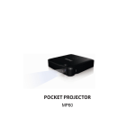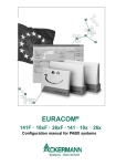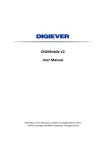
1
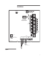
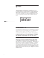
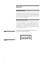
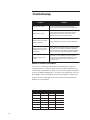
/ Marley Multicell Motor Sequencer / User Manual 00-1177 }Ê/iV }ià >ViÊNÊ>ÊÀÞÊ }ÊNÊ>ÀiÞ Installation Introduction The Marley 6 and 12 stage Multicell Motor Sequencers are designed to control multiple cell cooling towers in such a way that required cooling will be done with maximum efficiency and minimum wear to cooling tower mechanical equipment. Temperature is monitored at a common return line and fans are turned on as needed. The 6 stage Sequencer can control up to six single-speed fans or three two-speed fans. The 12 stage Sequencer can control up to 12 single-speed fans or six two-speed fans. Indicating lights and an illuminated temperature readout provide continuous information on the current status of the cooling system. Installation Remove the three retaining screws in the Sequencer board and remove the Sequencer. This will reveal two mounting slots near the top and two mounting holes near the bottom of the enclosure. Mount the enclosure on a flat sturdy surface. Avoid placing the panel in a twist or bind The Sequencer requires a single 120VAC source of power connected to terminals NEUTRAL and LINE as shown in Figure 1. Safety Ground Terminal must be connected to an earth ground. Connect the temperature sensor to terminals 1 and 2 on the input terminal strip. The sensor must be installed in a dry thermowell in the cooling tower water return line—see Figure 2. The sensor may be extended up to 500′ using #18 AWG shielded cable. If the remote set point feature is used, a 4 – 20 mA signal is connected to terminals 5 and 6 on the input terminal as shown. Refer to the Operation section. Each stage is controlled by a single set of normally open dry contacts. These contacts are to be connected in series within the control circuits of the fan motor starter coils. Terminals for these connections are provided in Marley motor starter panels—see Figure 3. The Sequencer should not be used with coil voltages above 120VAC. Warning The Multicell Motor Sequencers are strictly operating controls; under no circumstances should they be used as primary limit or safety controls. Each piece of equipment must have its own certified limit and safety controls required by local codes. This is the responsibility of the installing contractor who must verify proper operation and correct any safety problems prior to proceeding with the installation of the Marley Sequencers. Installation Serial No. LEAD STAGE ROTATION INCREMENT OFF Part No. AUTO Output 1 UP 85 F OFF SELECT SETTING AUTO ON DOWN Output 2 OFF 6 STAGE SEQUENCER OUTPUT 1 AUTO ON Output 3 OUTPUT 2 OFF LEAD STAGE INDICATORS AUTO OUTPUT 3 ON Output 4 OFF OUTPUT 4 AUTO ON Output 5 OUTPUT 5 OFF AUTO OUTPUT 6 ON Output 6 SYSTEM ACTIVE SIGNAL OFF AUTO ON System Active OFF NEUTRAL AUTO TEMP SAFETY GROUND MUST BE CONNECTED ON INPUTS LINE PRES. 4-20mA Sensor Com. Shield + Sensor Com. 1 2 3 4 5 6 SHUTDOWN Dry Contact Only 7 8 PROVE Dry Contact Only 9 10 11 12 OPTIONAL REMOTE SET POINT SENSOR 4-20 mA + MADE IN THE U.S.A. Figure 1 Installation SENSOR WATER RETURN LINE 1/2" NPT COUPLING THERMOWELL SENSOR WIRING Figure 2 THREE TWO-SPEED MARLEY BASIC PANELS CONTROLLED BY A 6 STAGE SEQUENCER N.O. 1 OUTPUT 1 C 9 1 16 N.O. 2 OUTPUT 2 C 14 2 N.O. 3 OUTPUT 3 C 9 3 N.O. 4 OUTPUT 4 C C 5 N.O. 6 OUTPUT 6 SYSTEM ACTIVE SIGNAL C 14 4 N.O. 5 OUTPUT 5 6 9 PANEL 2 16 14 PANEL 3 M Figure 3 PANEL 1 16 M M Operation The first step in operating the Sequencer is to select the proper sequence of operation. Located on the back of the panel are eight dip switches. For “normal” cooling—all single speed fans—switches 1 thru 4 must be set in the off position—see Figure 4. In this mode fans will be added until all fans are on. ON 1 2 3 4 5 6 7 8 Figure 4 Recommended method for 2-speed motors is low-low, high-high. Set switches 1, 2 and 4 off and switch 3 on—see Figure 5. In this mode fan 1 will start low, then upon added heat demand will be joined by fan 2 low until all fans are on low. Then fan 1 will transfer to high, followed by fan 2 high until all fans are on high. ON 1 2 3 4 5 6 7 8 Figure 5 An alternate method of operation for two-speed fans is low-high, low-high. Switches 1, 3 and 4 must be off and switch 2 must be on—see Figure 6. In this mode, fan 1 will start low, then upon added heat demand fan 1 will transfer to high, followed by fan 2 low, then fan 2 high. This sequence will be continued until all fans are on high as necessary to satisfy the cooling demand. There will never be more than one fan on low at the same time. ON Figure 6 1 2 3 4 5 6 7 8 Operation There are two options for cycling fans off. Last on, first off or first on, first off. With dip switch 5 in the off position, fans will be cycled off in the opposite order they were cycled on—last on, first off. By changing dip switch 5 to on—see Figure 7—this sequence can be reversed—first on, first off. This feature works for all three modes of operation described above. ON Figure 7 1 2 3 4 5 6 7 8 Set Point Selection — SP When power and the temperature sensor are connected to the sequencer, the water temperature will be displayed. Directly to the right of the display window are three push bottons—see Figure 1. Press the SELECT SETTING button once and the letters “SP” appear. Release the button and wait a few seconds. The set point temperature will be displayed. To change the set point, press the UP or DOWN button until the desired set point is displayed. Temperature display returns after a few seconds. Reaction Time — rE Reaction time is the minimum time permitted between stage changes. It is adjustable from 30 seconds to 8 minutes. To set the reaction time, press the SELECT SETTING button twice and release. The letters “rE” will appear. After a few seconds the reaction time will appear. To change the reaction time, press the UP or DOWN button until the desired reaction time is reached. Temperature display will return after a few seconds. Most multicell applications will operate within a 3 minute or longer reaction time. Settings too short may cause excessive cycling. Settings too long result in temperature swings Operation Note System Active Relay settings do not affect operation of cooling tower fans. See System Active Relay on page 8 for more info. System Active Delay — SA (Set to 0) Pressing the SELECT SETTING button three times will display “SA”. The system active delay will be displayed. The system active relay will deenergize when the last fan turns off. System Active Relay Start Delay — SE (Set to 0) Pressing the SELECT SETTING button four times will display “SE”. The start delay setting will be displayed. The system active relay will energize anytime a fan is running. Active Output Control Each output can be set for OFF, AUTO or ON by means of three-position selector switches. When set to OFF, the output is not functional, and the Sequencer will skip that output. When set for AUTO the output is enabled and will be cycled on and off automatically by the sequencer as the cooling load requires. When set for ON the output is on continuously regardless of cooling load requirements—see Figure 1. Red indicator lights at each output indicate the status of that output. Lead Stage Selection Control of lead stage selection is done with the lead stage selector switch located on the panel. With this switch in AUTO the lead stage is rotated every 24 hours. Each day a different stage is lead. Lead stage is indicated by green lamps on the panel. With the lead stage selector switch in OFF the lead stage does not rotate. The current lead stage remains lead stage until it is changed manually or the switch is returned to AUTO. To manually change the lead stage move the switch to INCREMENT and release. The lead stage will be advanced to the next available lead stage. If a stage is turned OFF, it cannot be selected as lead stage. When the system is set for two-speed motor operation, only low speed—odd numbered—stages can be lead stage. Operation System Active Relay In normal operation this relay is activated when any output is on. The N.O./ N.C. type C contacts of this relay may be used for customer’s building automation system or other required signals. The System Active selector switch controls this relay. When set to OFF the relay is deactivated. When set to AUTO the relay operates as described above. When set for ON the relay is on continuously—see Figure 1. Extermal Set Point Control The 6 and 12 stage Sequencer set point can be remotely controlled. To use this feature, set dip-switch 7 to on—see Figure 8—and connect a 4–20 mA signal to input terminals 5 (positive) and 6 (negative). An input of 4 mA will result in a set point of 40°F and an input of 20mA will result in a set point of 100°F This feature allows automatic setback for night or weekend operation, or automatic transfer to free cooling when connected to an external digital control system. Note The set point cannot be changed with the push buttons when connected for externnal set point control. ON Figure 8 1 2 3 4 5 6 7 8 Operation Programmed Offset — PO Pressing the SELECT SETTING button five times will display the letters “PO”. This function is only used when an external 4-20mA signal is being used to control the set point. The programmed offset feature accomplishes the same function as a zero and span adjustment. To use this feature apply a known 4 mA signal to input terminals 5+ and 6- and press the button once to observe the set point. If 40°F is not displayed allow the display to return to water temperature and press the SELECT SETTING button five times. “PO” will appear in the display. Adjust up or down as necessary until the analog signal from the system results in the desired set point being displayed. Next apply a 20 mA signal from the system and press the SELECT SETTING button once to display the set point. The set point should be 100°F with a 20 mA signal from the system. If necessary use the SELECT SETTING button to display the “PO” function and use the UP or DOWN button as required until the signal from the sytem produces the 100°F set point. Troubleshooting Problem Solution Display shows “ OPN” Sensor is not connected. Check sensor wiring. Sensor is defective. See sensor checkout procedure. Display shows “ SHT” Sensor is shorted. Remove sensor wires. Display should change to OPN. This indicates sensor is defective. See sensor checkout procedure. Display shows an incorrect water temperature. Sensor is defective. See sensor checkout procedure. Sequencer does not react. Temperature overshoot or undershoot. Check reaction time. Press selector push button twice and wait 5 seconds. Reaction time will be displayed— 30 seconds to 8 minutes. Shorten or lengthen reaction time as necessary to prevent temperature overshoot. Set point display shows “ OFF” Dip switch 7 is set to ON but no 4-20 mA signal is being received. If remote setpoint is desired, correct mA signal. If manual set point is desired, set dip switch 7 to OFF. Sensor Checkout Procedure The sensor is a thermistor and responds to temperature changes by varying resistance. To check a sensor, connect an ohmmeter across the sensor’s leads and read ohms. Below is a chart showing correct resistance in ohms for different temperatures. The sensor must be kept dry, and must be installed in a dry thermowell to sense water temperature. Exposure to moisture will result in damage to the sensor and incorrect temperature readings on the sequencer. 10 Temp Ohms Temp Ohms 40° F 13,040 75° F 5,250 45° F 11,374 80° F 4,649 50° F 9,944 85° F 4,125 55° F 8,714 90° F 3,667 60° F 7,653 95° F 3,266 65° F 6,736 100° F 2,914 70° F 5,941 110° F 2,332 Specifications 6 and 12 Stage Sequencer Input Voltage..................................................................................120VAC Power Consumption........................................................................... 30VA Output Contact Rating.......................................... 6 Amp Resistive, 1/3 HP Operating Ambient Temperature..............................................20° to 120°F Set Point Range......................................................................40° to 100°F Accuracy............................................................................................ ±1°F Reaction Time (selectable).................................... 30 seconds to 8 minutes Enclosure.......................................................................................NEMA 1 —dimensions...............................................................12.5″ x 12.5″ x 5.5″ Enclosure.................................................................................... NEMA 4X —dimensions........................................................................16″ x 16″ x 9″ Temperature Sensor................................................................... Thermistor 11 Cooling Technologies Balcke | Hamon Dry Cooling | Marley / 7401 W 129 Street // Overland Park, KS USA 66213 // +1 913 664 7400 // [email protected] // www.spxcooling.com / In the interest of technological progress, all products are subject to design and/or material change without notice. ©2006 SPX Cooling Technologies, Inc. | Printed in USA Manual 00-1177