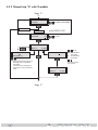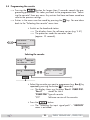
1
HDTV Digital QAM PHDQ 1000 ASI LAN KLASSE PHDQ 1001 English CLASS GSS Grundig SAT Systems GmbH Beuthener Strasse 43 D-90471 Nuremberg Phone: Fax: E-mail: Internet: +49 (0) 911 / 703 8877 +49 (0) 911 / 703 9210 [email protected] http://www.gss.de Contents 1 Safety regulations .....................................................................................................4 2 General information .................................................................................................4 2.1 Packing contents ..........................................................................................4 2.2 Meaning of the symbols used ........................................................................5 2.3 Technical data .............................................................................................5 2.4 Description .................................................................................................6 2.4.1 Input signal path “INROUTE” ..............................................................6 2.4.1.1 Menu setting “A+ASI = 1 B+ASI = 2”...................................6 2.4.1.2 Menu setting “A+B+ASI = 1 ASI = 2”...................................6 2.4.2 Output signal path “OUTROUTE” ........................................................7 2.4.2.1 Menu setting “ASI => ASI” ....................................................7 2.4.2.2 Menu setting “1 => ASI ASI => MA” ...................................7 2.4.2.3 Menu setting “2 => ASI ASI => MB” ....................................7 2.4.3 General ...........................................................................................8 2.5 Software query............................................................................................8 2.6 How the TPS module works ...........................................................................9 2.7 Explanation of the term “symbol rate” ..........................................................10 3 Assembly ............................................................................................................... 11 3.1 Installing the cassette..................................................................................11 3.2 EMC regulations ........................................................................................11 3.3 Connecting the cassette ..............................................................................12 3.4 Retrofitting a CA module ............................................................................13 4 The control panel at a glance .................................................................................. 14 4.1 Menu items ...............................................................................................14 4.2 Control panel ............................................................................................14 5 Programming ......................................................................................................... 15 5.1 Preparation ...............................................................................................15 5.2 Notes on level setting .................................................................................15 5.3 Programming procedure .............................................................................16 5.3.1 Channel strips “A” (without CA module) and “B”.................................16 5.3.2 Channel strip “A” with CA module ....................................................19 5.4 Programming the cassette ..........................................................................20 Selecting the cassette .................................................................................20 Selecting the input signal path .....................................................................21 Selecting the output signal path ...................................................................21 Setting the ASI transfer rate .........................................................................22 Setting the ASI options ...............................................................................23 Selecting the channel strip ..........................................................................24 Selecting channel / frequency setting ...........................................................24 Setting the output channel ...........................................................................25 Setting the output frequency ........................................................................25 Switching the modulator off or on ................................................................26 Adjusting the output levels of the channel strips .............................................26 -2- PHDQ 1000 ASI LAN / PHDQ 1001 Setting the LNB oscillator frequency .............................................................27 Setting the input symbol rate .......................................................................28 Setting the DVB mode ................................................................................28 Setting the input frequency ..........................................................................28 Testing the signal to noise ratio ....................................................................29 Setting the station filter ...............................................................................31 Setting the QAM modulation ......................................................................35 Inverting the user signal ..............................................................................35 Setting stuffing...........................................................................................36 Setting a substitute signal in the case of an incorrect input signal ....................37 Network Information Table (NIT) ..................................................................38 Network/operator identification ..................................................................39 Deleting a PID ...........................................................................................40 Renaming a PID.........................................................................................40 Saving settings ..........................................................................................41 5.4.1 Operation with a CA module ............................................................41 Setting the encoding (only PHDQ 1001) ............................................. 41 Setting the PID monitoring ................................................................42 Configuring the CA module ..............................................................43 Setting the station filter .....................................................................44 6 Final procedures .....................................................................................................46 7 Channel and frequency tables .................................................................................47 -3- PHDQ 1000 ASI LAN / PHDQ 1001 1 Safety regulations Caution UÊÃÃiLÞ]Ê ÃÌ>>ÌÊ >`Ê ÃiÀÛV}Ê Ã Õ`Ê LiÊ V>ÀÀi`Ê ÕÌÊ LÞÊ >ÕÌ ÀÃi`Ê electricians. UÊ-ÜÌV ÊvvÊÌ iÊ«iÀ>Ì}ÊÛÌ>}iÊvÊÌ iÊÃÞÃÌiÊLivÀiÊLi}}ÊÜÌ Ê>ÃÃiLÞÊ or service work or pull out the mains plug. UÊ ÊÌÊ«iÀvÀÊÃÌ>>ÌÊ>`ÊÃiÀÛViÊÜÀÊ`ÕÀ}ÊÌ Õ`iÀÃÌÀð UÊÃÌ>ÊÌ iÊÃÞÃÌiÊÃÊÌÊÜÊÌÊLiÊ>LiÊÌÊÛLÀ>Ìio Ê Ê Ê>Ê`ÕÃÌvÀii]Ê`ÀÞÊiÛÀiÌ -Ê ÊÊÃÕV Ê>Ê>iÀÊÌ >ÌÊÌÊÃÊ«ÀÌiVÌi`ÊvÀÊÃÌÕÀi]ÊvÕiÃ]Êë>à }ÊÜ>ÌiÀÊ>`Ê dampness - somewhere protected from direct sunlight - not within the immediate vicinity of heat sources - in an ambient temperature of -20 °C to +50 °C. UÊÃÕÀiÊÌ >ÌÊÌ iÊ i>`i`ÊÃÌ>ÌÊÃÊ>`iµÕ>ÌiÞÊÛiÌ>Ìi`°Ê Do not cover the ventilation slots. UÊiÜ>ÀiÊvÊà ÀÌÊVÀVÕÌÃÊ UÊ Ê>LÌÞÊÃÊ>VVi«Ìi`ÊvÀÊ>ÞÊ`>>}iÊV>ÕÃi`ÊLÞÊv>ÕÌÞÊViVÌÃÊÀÊ>«propriate handling. UÊ "LÃiÀÛiÊÌ iÊÀiiÛ>ÌÊÃÌ>`>À`Ã]ÊÀi}Õ>ÌÃÊ>`Ê}Õ`iiÃÊÊÌ iÊÃÌ>>ÌÊ>`Ê operation of antenna systems. UÊ>ÀÌ ÊÌ iÊSAT receiver in accordance with DIN EN 50083-1 / EN 60728-11 >`Ê6ÊänxxÊi>ÀÌ i`]ÊiµÕ«ÌiÌ>ÊL`}®°Ê U For further information please read the assembly instructions for the headend station used. Take action to prevent static discharge when working on the device. 2 General information 2.1 Packing contents 1 2 1 1 Cassette PHDQ 1000 ASI LAN or PHDQ 1001 HF cables CD (assembly instructions) Brief assembly instructions -4- PHDQ 1000 ASI LAN / PHDQ 1001 2.2 Meaning of the symbols used Important note —> UÊ General note Ê Ê *iÀvÀ}ÊÜÀà 2.3 Technical data The devices meet the following EU directives: ÓääÈÉxÉ ]ÊÓää{É£änÉ The product fulfils the guidelines and standards for CE labelling. HF input ÀiµÕiVÞÊÀ>}i\ÊÊ iÛiÊÀ>}i\Ê ÊÊ DVB-S modes: DVB-S2 modes: -ÞLÊÀ>ÌiÊ6-\Ê Ê -ÞLÊÀ>ÌiÊ6-Ó\ÊÊ Ê Ê Ê Ê Ê ÓxÊoÊÓ£xäÊâ ÈäÊ`6ÊoÊnäÊ`6 DVB-S 1/2 ]Ê2/3 ]Ê3/4 ]Ê5/6 ]Ê7/8 QPSK 1/2 ]Ê3/5 ]Ê2/3 ]Ê3/4 ]Ê4/5 ]Ê5/6 ]Ê8/9 ]Ê9/10 8PSK 3/5 ]Ê2/3 ]Ê3/4 ]Ê5/6 ]Ê8/9 ]Ê9/10 +*-\Ê Ê ÓÊoÊ{xÊ-ÞLÉà +*-\Ê £äÊoÊÎäÊ-ÞLÉà n*-\Ê £äÊoÊΣÊ-ÞLÉà HF output >iÃ\Ê ÊÊ ÀiµÕiVÞÊÀ>}i\ÊÊ Output level: Output impedance: -Ó£ÊoÊ È {Ó°äÊâÊoÊnÈä°äÊâÊ typ. 97 dBµV 75 Connections SAT inputs: HF output: -Ê«ÕÌ\Ê ÊÊ -ÊÕÌ«ÕÌ\Ê ÊÊ Connection strip (10-pin): RS-232 socket: Conditional access: 2 F sockets 1 IEC socket £Ê ÊÃViÌ]ÊÇxÊ £Ê ÊÃViÌ]ÊÇxÊ for supply voltages and control circuits serial interface for software update several channels can be decoded. -5- PHDQ 1000 ASI LAN / PHDQ 1001 2.4 Description / iÊ `ÕLiÊ ÌÀ>Ã`Õ>ÌÀÊ V>ÃÃiÌÌiÊ ÃÊ >Ê +*-VÛiÀÌiÀ]Ê Ü V Ê VÛiÀÌÃÊ >Ê stations modulated according to DVB-S / DVB-S2 standard into two QAM-modulated cable signals. The cassette has two digital SAT IF inputs and one HF output. Additionally it is equipped with an ASI input and an ASI output (ASI – Asynchronous Serial Interface acc. DIN EN 50083-9). The transport stream fed via the ASI socket can be inserted into the transport streams of the receiving stages via the TPS module. The signal path is set in the menu items input signal path “INROUTE” and output signal path ”OUTROUTE”. 2.4.1 Input signal path “INROUTE” 2.4.1.1 Menu setting “A+ASI = 1 B+ASI = 2” The transport streams of the receiving stage “TS A” and of the ASI input “TS ASI” generate the transport stream 1. The transport streams of the receiving stage “TS B” and of the ASI input “TS ASI” generate the transport stream 2. SAT input ”A“ Receiving stage "A" TS A CA module TPS Transport stream 1 TPS Transport stream 2 TS ASI ASI input SAT input ”B“ Receiving stage "B" TS B 2.4.1.2 Menu setting “A+B+ASI = 1 ASI = 2” The transport streams of the receiving stages “TS A” and “TS B” and of the ASI input “TS ASI” generate the transport stream 1. The “TS ASI” transport stream fed via the ASI input generates the transport stream 2. SAT input ”A“ Receiving stage "A" SAT input ”B“ Receiving stage "B" TS A CA module TS B TPS TS ASI Transport stream 1 Transport stream 2 ASI input -6- PHDQ 1000 ASI LAN / PHDQ 1001 2.4.2 Output signal path “OUTROUTE” 2.4.2.1 Menu setting “ASI => ASI” Transport stream 1 is made available via modulator “A»]ÊÌÀ>ëÀÌÊÃÌÀi>ÊÓÊÛ>Ê modulator “B” and the transport stream from the ASI input “TS ASI” via the ASI output. Modulator "A" Transport stream 1 Combiner Modulator "B" Transport stream 2 ASI input HF output TS ASI 2.4.2.2 Menu setting “1 => ASI ASI output ASI => MA” /À>ëÀÌÊÃÌÀi>Ê£ÊÃÊ>`iÊ>Û>>LiÊÛ>ÊÌ iÊ-ÊÕÌ«ÕÌ]ÊÌÀ>ëÀÌÊÃÌÀi>ÊÓÊÛ>Ê modulator “B” and the transport stream from the ASI input “TS ASI” via modulator “A” (MA). Transport stream 1 ASI input ASI output TS ASI Modulator "A" Combiner HF output Modulator "B" Transport stream 2 2.4.2.3 Menu setting “2 => ASI ASI => MB” Transport stream 1 is made available via modulator “A»]ÊÌÀ>ëÀÌÊÃÌÀi>ÊÓÊÛ>Ê the ASI output and the transport stream from the ASI input “TS ASI” via modulator “B” (MB). Modulator "A" Transport stream 1 Combiner ASI input TS ASI HF output Modulator "B" Transport stream 2 ASI output -7- PHDQ 1000 ASI LAN / PHDQ 1001 2.4.3 General The cassette is equipped with two channel strips (“A” and “B”). The channel ÃÌÀ«ÃÊVÃÃÌÊvÊÌ iÊ`}Ì>ÊÌÕiÀÃ]ÊÌ iÊ`}Ì>ÊÃ}>Ê«Ài«>À>ÌÊÕÌÃÊ>`ÊÌ iÊÕÌput converter. The channel strips are indicated in the head-end station display with “Bx …A” and “Bx …B”. Using an adequate CA module encoded channels can be decoded via channel strip “A”. In addition cassette PHDQ 1001 is able to encode uncoded channels via an adequate CA module. The control of the cassette takes place via the control unit of the head-end station. Two LEDs indicate if the respective channel strip is switched on (LED illuminates) ÀÊvv]Ê>`Ê>ÃÊ«ÀÛ`iÊ>Ê`V>ÌÊvÊÌ iÊÃ}>ʵÕ>ÌÞÊL>Ãi`ÊÊÌ iÀÊVÕÀ°Ê Additionally the quality of the transport stream received is displayed (“CN…”). The integrated TPS module (Transport Stream Processing) processes the data from the demodulated transport streams. The HF output signals are sent through the HF output of the cassette to the output collector. The common output level of the channel strips can be set at the output collector. Additionally a transport stream is made available via the ASI output dependent on the signal path set. 7 iÊÌ iÊ i>`i`ÊÃÌ>ÌÊÃÊÃÜÌV i`Ê]ÊÌ iÊÌÜiÊ Ê`ë>ÞÊà ÜÃÊÌ iÊ software version of the control unit. To operate this cassette the software version of the control unit must be “V 41” or higher. You can find the current operating software for the control unit and Ì iÊV>ÃÃiÌÌi]ÊÌ iÊÃvÌÜ>ÀiʺBE-Flash” and the current assembly instructions on the website “www.gss.de”. The cassette is designed for use in the following head-end stations: – PSU 12 – PSU 8 – PGT 8 – PST 19-1 2.5 Software query Control unit vÊiViÃÃ>ÀÞ]ÊÞÕÊV>Ê>VÌÛ>ÌiÊÌ iÊ`V>ÌÊvÊÌ iÊÃvÌÜ>ÀiÊÛiÀÃÊvÊÌ iÊVtrol unit manually: UÊ*ÀiÃÃÊ>ÞÊÌÜÊiÞÃÊÊÌ iÊVÌÀÊÕÌÊvÊÌ iÊ i>`i`ÊÃÌ>ÌÊÃÕÌ>iÕÃÞÊ ÕÌÊÌ iÊ`ë>ÞÊ}iÃÊ`>ÀÊ>`ÊÌ iÊÃvÌÜ>ÀiÊÛiÀÃ]Êi°}°ÊºV 41” appears. -8- PHDQ 1000 ASI LAN / PHDQ 1001 2.6 How the TPS module works vÌiÀÊ`iV`}Ê+*-ÊÀÊn*-`Õ>Ìi`ÊÃ}>Ã]ÊÌ iÊ`i`Õ>Ìi`Ê`>Ì>ÊÃÌÀi>Ê V>ÊLiÊ>VViÃÃi`ÊÛ>ÊÌ iÊÌi}À>Ìi`Ê/*-Ê`Õi°Ê/ ÃÊ`>Ì>ÊÃÌÀi>]Ê>ÃÊV>i`Ê ÌÀ>ëÀÌÊÃÌÀi>]ÊVÌ>ÃÊÃiÛiÀ>ÊÃÌ>ÌÃÊÊ>ÊÌ iÀÊV«iÌÃÊÛ`i]Ê>Õ`]Ê `>Ì>Ê>`ÊÃiÀÛViÊvÀ>Ì®]ÊÜ V ÊV>ÊLiÊV >}i`ÊÕÃ}ÊÌ iÊ/*-Ê`Õi° The individual functions Station filter `Û`Õ>ÊÃÌ>ÌÃÊV>ÊLiÊ`iiÌi`°Ê/ ÃÊÀi`ÕViÃÊÌ iÊ`>Ì>ÊÀ>ÌiÊ>`]ÊVÃiµÕiÌÞ]Ê the output symbol rate required. Additionally stations of the different transport streams can be assembled to a new transport stream. Stuffing / iÊÌÀ>ëÀÌÊÃÌÀi>ÊÃÊ«>``i`ÊÕÃ}ÊÜ >ÌÊÃÊÜÊ>ÃÊâiÀÊ`>Ì>°Ê/ ÃÊiÃÕÀiÃÊ a steady and constant output symbol rate. Changing the NIT The transport stream contains data in the form of tables which the receivers evaluate and require for convenient use. The TPS module can adjust the “Network Information Table” (NIT) to accommodate the new station data. The “NIT” contains data which is required by the set-top box for the automatic search feature. Changing the operator ID (CAT) Some network operators transmit an operator ID in the data stream (e.g. visAvision). By changing the CAT the operator ID can be adjusted to the demands. -9- PHDQ 1000 ASI LAN / PHDQ 1001 2.7 Explanation of the term “symbol rate” Modulation schemes such as QPSK and QAM transmit multiple bits simultaneously. These are referred to as symbols. In addition to the user data flow which ÌÀ>ÃÌÃÊÛ`iÊ>`Ê>Õ`ÊvÀ>Ì]ÊiÀÀÀÊVÀÀiVÌÊLÌÃÊ>ÀiÊÌÀ>ÃviÀÀi`°Ê/ iÊ FEC number states the ratio of user bits to the complete transmitted bits. The output symbol rate is calculated as follows: 256-QAM: 128-QAM: 64-QAM: 32-QAM: 16-QAM: 4-QAM: SR (A) = FEC x 1/4 x SR (E) SR (A) = FEC x 2/7 x SR (E) SR (A) = FEC x 1/3 x SR (E) SR (A) = FEC x 2/5 x SR (E) SR (A) = FEC x 1/2 x SR (E) SR (A) = FEC x 1/1 x SR (E) Example: "ÕÌ«ÕÌÊÃÞLÊÀ>ÌiÊÈ{+] FEC= 3/4] «ÕÌÊÃÞLÊÀ>ÌiÊ-,Ê®ÊrÊÓÇ]xääÊkSymb/s SR (A) = 3/4 x 1/3ÊÝÊÓÇ]xääÊkSymb/s SR (A) = 6,875 kSymb/s Note: vÊʺ »ÊÃÊÃÌ>Ìi`ÊÊÌ iÊÃÌ>ÌÊÃÌÃ]ÊÌÊV>ÊLiÊ>ÃÃÕi`ÊÌÊLi “FEC = 3/4”. Reception from a transponder with a very low symbol rate (SCPC station) The extremely low data rate means that the output symbol rate is very low. If Ì iÀiÊ>ÀiÊÀiVi«ÌÊ«ÀLiÃÊÜÌ Ê`vviÀiÌÊ`}Ì>ÊÀiViÛiÀÃ]ÊÃiÌÊÕÌ«ÕÌÊÃÞLÊ rate to a higher value. Defined symbol rates -iÊV>LiÊ«iÀ>ÌÀÃÊëiVvÞÊ>ÊvÝi`ÊÃÞLÊÀ>ÌiÊi°}°ÊÈ]ääÊ-ÞLÉî°Ê - 10 - PHDQ 1000 ASI LAN / PHDQ 1001 3 Assembly 3.1 Installing the cassette – Ensure the head-end station is mounted so it will not be able to vibrate. Û`]ÊvÀÊiÝ>«i]ÊÕÌ}ÊÌ iÊ i>`i`ÊÃÌ>ÌÊÌÊ>ÊvÌÊà >vÌÊÀÊ>ÞÊ other wall or floor construction that vibrates in a similar way. – Before installing or changing a cassette unplug the power cable from the mains power socket. UÊ,iÛiÊÌ iÊv>ÃÌi}ÊÃVÀiÜÃÊ1 of an unoccupied slot from the bracket of the head-end station. UÊÃiÀÌÊÌ iÊV>ÃÃiÌÌiÊÊÌ ÃÊÃÌÊ>`Ê«Õà ÊÌÊÌÊÌ iÊ ÕÃ}° UÊ}ÊÌ iÊV>ÃÃiÌÌiÊ>`Ê>««ÞÊÃ} ÌÊ«ÀiÃÃÕÀiÊÌÊViVÌÊÌÊÌÊÌ iÊViVÌÃÊvÊ the board and the HF bus bar. UÊ>ÃÌiÊÌ iÊV>ÃÃiÌÌiÊÜÌ ÊÌ iÊÃVÀiÜÃÊ1. ACHTUNG! Vor dem Kassettenwechsel unbedingt denNetzstecker ziehen. KASSETTE KASSETTE KASSETTE KASSETTE KASSETTE KASSETTE KASSETTE KASSETTE KASSETTE KASSETTE KASSETTE KASSETTE 0° AUSGANG max. 90 dBµV CAUTION! Before changing cassettes remove mains plug. Grundig SAT Systems 3.2 EMC regulations KLASSE To comply with the current EMC regulations, it is necessary to connect the lines leading in and out of the head-end station using cable terminals. CLASS The attenuation of shielding of the connection lines for ASI and antenna must meet the requirements for “Class A”. When mounting the cassette in a PGT 8 or PST 19-1 head-end station which is installed in a 19" cabinet, make sure the connections leading in and out for the 19" cabinet are made using cable terminals. - 11 - PHDQ 1000 ASI LAN / PHDQ 1001 UÊÃiÀÌÊÌ iÊÀiµÕÀi`ÊÕLiÀÊvÊV>LiÊÌiÀ>ÃÊÊÌ iÊ«i}ÃÊ«ÀÛ`i`ÊÊÌ iÊ head-end station or in the 19" cabinet. —> Cable terminals are not included in the scope of delivery. Tighten the nut on the cable terminal until the teeth on the lock washer have penetrated the exterior coating and a good connection is made between the housing and cable terminal. 3.3 Connecting the cassette SAT input "A" ASI input Slot for a CA module SAT input "B" LAN ASI output RS 232 UÊPlug the SAT input cables into the SAT input sockets “SAT input A” 2 (channel strip “A”) and “SAT input B” 1 (channel strip “B”). —> LAN socket 3 (intended for additional functions) UÊ iVÌÊÌ iÊ-ÊÃViÌÃÊ4 and 5. U Connect the head-end station to the mains power supply. 6 7 Slot for a CA module “RS-232“ socket The operating software of the cassette can be updated via the 9-Pin D-SUB socket “RS232” using a PC or notebook and the software “BE-Flash”. You can find the current operating software on the website “www.gss.de”. - 12 - PHDQ 1000 ASI LAN / PHDQ 1001 3.4 Retrofitting a CA module The cassette is equipped with a common interface. It allows you to connect a CA module for various encryption systems and service providers. Encoded channels can only be decoded with a CA module suitable for the encoding system and the corresponding smart card. The smart card contains all the infor>ÌÊvÀÊ>ÕÌ ÀÃ>Ì]Ê`iV`}Ê>`ÊÃÕLÃVÀ«Ì° Ê Caution – Check with the distributor or manufacturer of the CA module to be used to ensure that it is suitable for decoding several channels. – The hardware and software of this cassette have been thoroughly prepared and tested. – Any changes made by programme providers to the structures in the programme data might impair or even prevent this function. qÊ 7 iÊÜÀ}ÊÜÌ ÊÌ iÊ Ê`Õi]Ê«i>ÃiÊÀi>`ÊÌ iÊVÀÀië`}Ê«erating manual from the respective provider. UÊÃiÀÌÊÌ iÊÃ>ÀÌÊV>À` into the CA module so that the chip on the smart card faces the thicker side (top) of the CA module. UÊÃiÀÌÊÌ iÊ Ê`ÕiÊÌÊÌ iÊÃÌ 6 (s. chap. 3.3) with the top side of the CA module facing the top side of the cassette. UÊ*Õà ÊÌ iÊ Ê`ÕiÊÜÌ ÕÌÊV>Ì}ÊÌÊÌ iÊ}Õ`iÊÀ>ÃÊvÊÌ iÊ ÊÃÌÊ6 and contact it to the common interface. - 13 - PHDQ 1000 ASI LAN / PHDQ 1001 4 The control panel at a glance 4.1 Menu items Programme the cassette using the buttons on the control unit of the head-end station. The two-line display of the control unit then shows the menus. The parameters and functions to be set are underlined. Use the key to select the following main menu items: – Input signal path – Output signal path BE-Remote V41 – Channel strip PROFESSIONAL – Selecting channel / frequency setting – Output channel / output frequency – Output level – LNB oscillator frequency – Input symbol rate – Input frequency – Station filter – QAM modulation – Stuffing – Substitute signal – Network Information Table (NIT) – Network/operator identification – Deleting a PID – Renaming a PID 4.2 Control panel The key pad on the head-end station is used to scroll through the menus and menu items one at a time: scrolls forward through the menus. select parameters in the menus. ÃiÌÊÛ>ÕiÃ]ÊÌ>ÌiÊ>VÌð selects sub-menus. scrolls backward through the menus. saves all entries. - 14 - PHDQ 1000 ASI LAN / PHDQ 1001 5 Programming 5.1 Preparation UÊ iVÌÊÌ iÊÌiÃÌÊÀiViÛiÀÊÌÊÌ iÊÊÕÌ«ÕÌÊÀÊÌ iÊÌiÃÌÊÕÌ«ÕÌÊvÊÌ iÊ i>`i`Ê station. UÊ-iÌÊÌ iÊÕÌ«ÕÌÊV >iÊÉÊÕÌ«ÕÌÊvÀiµÕiVÞÊvÊÌ iÊcassette (s. page 25) and adjust the TV test receiver to this channel. UÊSwitch on the channel strip (modulator) if necessary (s. page 26). For each V >iÊ ÃÌÀ«]Ê Ì iÀiÊ ÃÊ >Ê ÃÌ>ÌÕÃÊ Ê Ü V Ê `V>ÌiÃÊ vÊ Ì iÊ V >iÊ ÃÌÀ«Ê ÃÊ switched on. Status LED Channel strip "B" Status LED Channel strip "A" UÊ>>ViÊÌ iÊÕÌ«ÕÌÊiÛiÃÊvÊÌ iÊV >iÊÃÌÀ«ÃʺA” and “B” if the difference in level is 1 dB (page 26). 5.2 Notes on level setting In order to prevent interference within the head-end station and the cable sysÌi]ÊÌ iÊÕÌ«ÕÌÊiÛiÊvÊÌ iÊV>ÃÃiÌÌiÊÕÃÌÊLiÊ`iVÀi>Ãi`ÊLÞÊ£äÊ`ÊV«>Ài`ÊÌÊ >>}ÕiÊV>ÃÃiÌÌiÃÊ>ÌÊÈ{Ê+]Ê>`ÊLÞÊ{Ê`ÊV«>Ài`ÊÌÊ>>}ÕiÊV>ÃÃiÌÌiÃÊ at 256 QAM. UÊi>ÃÕÀiÊÌ iÊÕÌ«ÕÌÊiÛiÃÊvÊÌ iÊÌ iÀÊV>ÃÃiÌÌiÃÊ>`ÊÌÕiÊÌ iÊÌÊ>ÊÕvÀÊ output level using the appropriate level controls or software dependent on the head-end station used. Please regard the assembly instructions of the respective head-end station. - 15 - PHDQ 1000 ASI LAN / PHDQ 1001 5.3 Programming procedure 5.3.1 Channel strips “A” (without CA module) and “B” Ein / On BE–Remote V 41 please wait … t > 10 s Bx 1A TWIN-SAT C5-12,S3-24 C07 + Box 4 Bx 1A TWIN-SAT Böx 4 TWIN-SAT Bx 5A DVBT-DVBT C5-12,S3-24 C07 C5-12,S3-24 C07 BD3 C09 DVBS2-TPM V 1 – – – A Page 18 Bx 4 INROUTE A+B+ASI=1 Bx 4 1=>ASI ASI=2 A+ASI=1 B+ASI=2 / A+B+ASI=1 ASI=2 Bx 4 OUTROUTE ASI RATE Ï/Å 108000 KBits ASI=>MA 1=>ASI ASI=>MA 2=>ASI ASI=>MB ASI=>ASI Bx 4 ASI OPTION 188 pos. cont. Ï / Å 188 / 204 positive / negativ continuous / burst B Page 18 Bx 4 LINE Line A <= => Line B Bx 4A Ï/Å Line A / Line B OUTPUT Channel Bx 4A S21 Channel / Freq. OUTPUT on Ï/Å on / off - 16 - PHDQ 1000 ASI LAN / PHDQ 1001 Bx 4A LEVEL 0 dB 0 … -10 dB Bx 4A LNB Ï/Å SYMBOL Ï/Å 10600 MHz Ï/Å Bx 4A 27500 Ï/Å DVB-S Bx 4A 11836 -1.8 Bx 4A Filter DVB-S / DVB-S 2 … FREQ Bx 4A CN 12 12.0 dB PROGRAM C/N (+ 9.6) OK Bx 4A TV + off Ï/Å Bx 4B TV + Ï/Å TV + Bx 4A Ï/Å Bx 4A 4 … 256 64-QAM Kanalzug “A” mit CA-Modul Channel strip “A“ with CA module QAM normal nächster Service (Programm) next service (station) PROGRAM Filter ohne CA-Modul without CA module Kanalzug “B” Channel strip “B“ nächster Service (Programm) next service (station) Programme entfernen / hinzufügen Removing / activating stations 01/10 . . . . . nächster Service (Programm) next service (station) Programme entfernen / hinzufügen Removing / activating stations 02/19 SWF3 Å Programme entfernen / hinzufügen Removing / activating stations 01/10 Das Erste ASI Anzeige: Signalqualität Display: Signal quality on on / off C Page 19 D Ï/Å normal / inverse - 17 - PHDQ 1000 ASI LAN / PHDQ 1001 Bx 4A STUFFING Ï/Å SR=6900 (6325) Bx 4A FAILURE Null Packets Null Packets … Single Carrier Bx 4A on / off Ï/Å NIT off => Make Bx 4A CAT-ID 0XDE00 Ï/Å Ï/Å off Bx 4A DROP PID 0x0000 Ï/Å Å Make Bx 4A on / off Ï/Å off REMAP 0x0000 –> 0000 off on / off Page 16 Ï/Å on / off B A M - 18 - PHDQ 1000 ASI LAN / PHDQ 1001 5.3.2 Channel strip “A” with CA module Page 17 C Bx 4A CA scramble scramble / descramble scramble only PHDQ 1001 descramble Bx 4A CA PID Check on Bx 4A M CA Menu <= Bx 4A 01/03 MENU on / off => Edit X / 0 Ï Å Bx 4A TV X 04/09 . . . . Information *) S *) Die angezeigte Information ist abhängig vom verwendeten CA-Modul. The information displayed is dependent on the CA module used. X – 0 – entschlüsselt decrypted verschlüsselt encrypted Ï/Å nächster Service next service Bx 4A Menu <= CA => Edit D Page 17 - 19 - PHDQ 1000 ASI LAN / PHDQ 1001 5.4 Programming the cassette —> Pressing the button for longer than 2 seconds cancels the programming procedure. This takes you back to the programme item “Selecting the cassette” from any menu. Any entries that have not been saved are reset to the previous settings. —> Entries in the menus can be saved by pressing the key. You are taken back to the “Selecting the cassette” menu item. Ein / On BE–Remote UÊ-ÜÌV ÊÊÌ iÊ i>`i`ÊÃÌ>Ì —> The display shows the software version (e.g. V 41) —> The processor reads the cassettes‘ data (approx. 10 seconds). _ V 41 please wait … t > 10 s Selecting the cassette Bx 1A TWIN-SAT C5-12,S3-24 C07 + Box 4 V 1 DVBS2-TPM – – – Bx 1A TWIN-SAT Böx 4 TWIN-SAT Bx 5A DVBT-DVBT C5-12,S3-24 C07 C5-12,S3-24 C07 BD3 C09 A UÊ-iiVÌÊÌ iÊcassette you want to programme (e.g. Box 4) by repeatedly pressing the button if necessary. —> The display shows e.g. the menu “Box 4 DVBS2-TPM“: “Box 4” stands for slot 4 ”DVBS2-TPM” Type of cassette ”V 1” Software version of the cassette UÊ*ÀiÃÃÊÌ iÊ button. —> The “Selecting the input signal path” – “INROUTE” menu is activated. - 20 - PHDQ 1000 ASI LAN / PHDQ 1001 Selecting the input signal path In this menu you define the signal path of the input transport streams. Menu setting “A+ASI = 1 B+ASI = 2” ðÊV >«°ÊÓ°{°£°£]Ê«>}iÊÈ®° Menu setting “A+B+ASI = 1 ðÊV >«°ÊÓ°{°£°Ó]Ê«>}iÊÈ®° Bx 4 ASI = 2” INROUTE A+B+ASI=1 ASI=2 A+ASI=1 B+ASI=2 / A+B+ASI=1 ASI=2 UÊ1ÃiÊÌ iÊ buttons to select the signal path wished. UÊ*ÀiÃÃÊÌ iÊ button. —> The “Selecting the output signal path” – “OUTROUTE” menu is activated. Selecting the output signal path In this menu you define the signal path of the output transport streams. Menu setting “ASI => ASI” Ê Ã°ÊV >«°ÊÓ°{°Ó°£]Ê«>}iÊÇ®° Menu setting “1 => ASI ASI => MA” Ê Ã°ÊV >«°ÊÓ°{°Ó°Ó]Ê«>}iÊÇ®° Menu setting “2 => ASI ASI => MB” Ê Ã°ÊV >«°ÊÓ°{°Ó°Î]Ê«>}iÊÇ®° Bx 4 1=>ASI OUTROUTE ASI=>MA Bx 4 ASI RATE Ï/Å 108000 KBits 1=>ASI ASI=>MA 2=>ASI ASI=>MB ASI=>ASI UÊ1ÃiÊÌ iÊ Bx 4 ASI OPTION Ï / Å 188 / 204 buttons to select the signal path wished. - 21 - PHDQ 1000 ASI LAN / PHDQ 1001 UÊvÊÞÕÊ`ÊÌÊÜ>ÌÊÌÊ`Ê-ÊÃiÌÌ}Ã]Ê«ÀiÃÃÊÌ iÊ button. —> The “Selecting the channel strip” – “LINE” menu is activated (page 24). UÊ*ÀiÃÃÊÌ iÊ button. —> The “Setting the ASI transfer rate” – “ASI RATE” menu is activated. Setting the ASI transfer rate In this menu you set the transfer rate for the ASI component connected. For this setting please take the required information from the documentation (technical data) of the ASI component to be connected. Bx 4 1=>ASI OUTROUTE ASI=>MA Bx 4 ASI RATE Ï/Å 108000 KBits 1=>ASI ASI=>MA 2=>ASI ASI=>MB ASI=>ASI Bx 4 ASI OPTION Ï / Å 188 / 204 UÊ1ÃiÊÌ i buttons to place the cursor under the digits to be set for the transfer rate then use the buttons to set the transfer rate wished. UÊ*ÀiÃÃÊÌ iÊ button. —> The “Setting the ASI options” – “ASI OPTION” menu is activated. - 22 - PHDQ 1000 ASI LAN / PHDQ 1001 Setting the ASI options Ê Ì ÃÊ iÕÊ ÞÕÊ `iviÊ Ì iÊ ÃâiÊ vÊ Ì iÊ `>Ì>Ê «>ViÌÃ]Ê Ì iÀÊ polarity and the type of transmission. For this setting please take the required information from the documentation (technical data) of the ASI component to be connected. 2=>ASI ASI=>MB ASI=>ASI Bx 4 ASI OPTION 188 pos. cont. Ï / Å 188 / 204 positive / negativ continuous / burst UÊ*ÀiÃÃÊÌ iÊ ÊLÕÌÌÃÊÌÊÃiÌÊÌ iÊÃâiÊvÊÌ iÊ`>Ì>Ê«>ViÌÃÊ (“188” or “204” bits). UÊvÊ Ì iÊ «>ÀÌÞÊ vÊ Ì iÊ `>Ì>Ê ÌÊ LiÊ ÌÀ>ÃÌÌi`Ê >ÃÊ ÌÊ LiÊ V >}i`]Ê«ÀiÃÃÊÌ i buttons to place the cursor under “pos.” (positive – standard) and using the buttons set to “neg.” (negative). UÊ/ÊV >}iÊÌ iÊÌÞ«iÊvÊÌÀ>ÃÃÃÊ«ÀiÃÃÊÌ i buttons to position the cursor under “cont.” (continuous – standard) and using the set to “burst”. —> Setting “cont.” The data packets of the user data are collected to a great data packet in the transport stream. —> Seting “burst” The data packets of the user data are spaced out evenly in the transport stream. UÊ*ÀiÃÃÊÌ iÊ button. —> The “Selecting the channel strip” – “LINE” menu is activated. - 23 - PHDQ 1000 ASI LAN / PHDQ 1001 Selecting the channel strip B Bx 4 LINE Line A <= => Line B Ï/Å Line A / Line B UÊÞÊ«ÀiÃÃ} select channel strip “A” (“Line A”) or select channel strip “B” (“Line B”) by pressing the button. UÊ*ÀiÃÃÊÌ iÊ button. —> The “Selecting channel / frequency setting” – “OUTPUT” menu is activated. Selecting channel / frequency setting ÊÌ ÃÊiÕ]ÊÞÕÊV>ÊÃiiVÌÊÌ iÊV >iÊÀÊvÀiµÕiÊVÞÊÃiÌÌ}Ê for the adjustment of the HF output. The channel setting coviÀÃÊÌ iÊÀ>}iÊvÊV >iÃÊ-Ó£ÊoÊ È]ÊÌ iÊvÀiµÕiVÞÊÃiÌÌ}Ê VÛiÀÃÊÌ iÊÀ>}iÊvÀÊ{Ó°äÊâÊÌÊnÈä°äÊâ° The QAM signal is normally transmitted with a bandwidth of nÊâ°Ê/ ÃÊi>ÃÊÌ >ÌÊÞÕÊV>ÊÞÊÕÃiÊÌ iÊV >i centre frequency of the existing channel grid in the range of chaniÃÊ-Ó£ÊoÊ ÈÊvÀiµÕiVÞÊ}À`ÊnÊâ®°Ê/ iÊ ,Êchannel }À`Ê ÃÊ ÇÊâÊ Ê Ì iÊ À>}iÊ vÊ Ì iÊ ÜiÀÊ vÀiµÕiVÞÊ L>`ÃÊ V >iÃÊ ÓÊoÊ-Óä®°Ê/ iÀivÀiÊÌ iÊvÀiµÕiVÞÊÃiÌÌ}ÊÃÊÕÃi`Ê here. If one uses the existing channel }À`ÊvÊÇÊâÊÊÌ iÃiÊ channel ranges]ÊÌ ÃÊÜÊÀiÃÕÌÊÊÌiÀviÀiViÊÛiÀ>««}®Ê ÜÌ ÊÌ iÊnÊâÊ+ÊÃ}>Ê«>V>}iÃ]ÊÌ ÕÃÊV>ÕÃ}ÊÌÀ>Ãmission problems. For programming in these channel ranges and in the frequenVÞÊÀ>}iÃÊLiÜÊÌ i]ÊÜiÊÀiVi`ÊÃÌ>ÀÌ}ÊÜÌ ÊV >iÊ -Ó£ÊÉÊÎäÈÊâÊ}}ÊL>VÊÊÃÌi«ÃÊvÊnÊâÊðÊvÀiµÕiVÞÊ Ì>LiÊÊ«>}iÊ{Ç®]ÊÀÊÀi`ÕV}ÊÌ iÊL>`Ü`Ì ÊvÊÌ iÊ+Ê output signal by removing stations. - 24 - PHDQ 1000 ASI LAN / PHDQ 1001 Bx 4A OUTPUT Channel Channel / Freq. UÊ1ÃiÊ to select channel setting “Channel” or frequency setting “Freq.”. UÊ*ÀiÃÃÊÌ iÊ button. —> The “Setting the output channel” or “Setting the output frequency” – “OUTPUT” menu is activated. Setting the output channel In this menu you set the output channel of the channel strip. Additionally the modulator of the channel strip can be switched off or on (page 26). Bx 4A S21 OUTPUT on Ï/Å on / off UÊ Use the buttons to set the output channel. Setting the output frequency In this menu you set the output frequency of the channel strip {Ó°äÊoÊnÈä°äÊâ®. Additionally the modulator of the channel strip can be switched off or on (page 26). Ï/Å Bx 4A OUTPUT 466.00 on UÊ1ÃiÊÌ i Ï/Å on / off buttons to place the cursor under the digit - 25 - PHDQ 1000 ASI LAN / PHDQ 1001 to be set for the frequency display then use the output frequency wished. to set Switching the modulator off or on UÊ/Ê ÃÜÌV Ê vvÊ Ì iÊ `Õ>ÌÀÊ «>ViÊ Ì iÊ VÕÀÃÀÊ Õ`iÀÊ ºon” using the button and switch “off” the modulator of the channel strip using the buttons. —> The switched off modulator is indicated by “ - - - “ in the display. —> The status LED is switched off (s. also page 15). UÊvÊÌ iÊ`Õ>ÌÀÊÃÊÃÜÌV i`ʺoff” use the it “on”. to switch UÊ*ÀiÃÃÊÌ iÊ button. —> The “Adjusting the output levels of the channel strips” – “LEVEL” menu is activated. Adjusting the output levels of the channel strips This menu item is used to set the output levels of the modulators of the channel strips “A” and “B” to the same value. Bx 4A 0 dB LEVEL 0 … -10 dB UÊi>ÃÕÀiÊ >`Ê ÌiÊ `ÜÊ Ì iÊ ÕÌ«ÕÌÊ iÛiÊ vÊ Ì iÊ V >iÊ strip. To adjust the output level to the output levels of theother cassettes please pay attention to chapter 7 “Final procedures”. UÊÞÊÀi«i>Ìi`ÞÊ«ÀiÃÃ}ÊÌ iÊ button scroll back to the “Selecting the channel strip” menu. UÊ -iiVÌÊÌ iÊÌ iÀÊV >iÊÃÌÀ« (page 24) and set the following menu items: UÊ º-iiVÌ}ÊV >iÊÉÊvÀiµÕiVÞÊÃiÌÌ}»]Ê«>}iÊÓ{ UÊ º-iÌÌ}Ê Ì iÊ ÕÌ«ÕÌÊ V >i»Ê ÀÊ º-iÌÌ}Ê Ì iÊ ÕÌ«ÕÌÊ vÀiµÕiVÞ»]Ê«>}iÊÓx - 26 - PHDQ 1000 ASI LAN / PHDQ 1001 UÊ -ÜÌV ÊÊÌ iÊ`Õ>ÌÀÊvÊiViÃÃ>ÀÞ]Ê«>}iÊÓÈ UÊ i>ÃÕÀiÊ>`ÊÌiÊ`ÜÊÌ iÊÕÌ«ÕÌÊiÛi° UÊVÌÛ>ÌiÊ Ì iÊ “LEVEL” menu of the channel strip with the higher output level. UÊÞÊ «ÀiÃÃng adjust the higher output level of one channel strip to the lower output level of the other channel strip incrementally from “0” to “–10 dB”. UÊ*ÀiÃÃÊÌ iÊ button. —> The “Setting the LNB oscillator frequency” – “LNB” menu is activated. Setting the LNB oscillator frequency Set the oscillator frequency of the LNB used in this menu. Bx 4A LNB Ï/Å 10600 MHz UÊ1ÃiÊ to place the cursor under the digit to be set for the frequency display. UÊ*ÀiÃÃÊ to enter the oscillator frequency of the LNB used. UÊ*ÀiÃÃÊÌ iÊ button. —> The “Setting the input symbol rate” – “SYMBOL” menu is activated. - 27 - PHDQ 1000 ASI LAN / PHDQ 1001 Setting the input symbol rate The symbol rates of the satellite transponders can be found in Ì iÊVÕÀÀiÌÊV >iÊÌ>LiÊvÊÌ iÊÃ>ÌiÌiÊ«iÀ>ÌÀ]ÊÊÛ>ÀÕÃÊ Ã>ÌiÌiÊ>}>âiÃÊ>`ÊÊÌ iÊÌiÀiÌ° Ï/Å Bx 4A 27500 SYMBOL DVB-S Ï/Å DVB-S / DVB-S 2 … UÊ1ÃiÊ to position the cursor under the digit to be set for the symbol rate displayed. UÊ*ÀiÃà to enter the values of the symbol rate. Setting the DVB mode / iÊ V>ÃÃiÌÌiÊ ÀiV}âiÃÊ Ì iÊ ÌÀ>ÃÌÌi`Ê 6Ê `iÊ >`Ê switches over between the normal QPSK mode (DVB-S) and Ì iÊ 6-ÓÊ `i°Ê ,iViÛ}Ê ÃÌ>ÌÃÊ ÜÌ Ê 6-ÓÊ `i]Ê we suggest to preset the DVB mode to shorten the time for searching stations. UÊ1ÃiÊÌ iÊ button to place the cursor under “DVB-S” and set the required DVB-S2-mode with the buttons . UÊ*ÀiÃÃÊÌ iÊ button. —> The “Setting the input frequency” – “FREQ” menu is activated. Setting the input frequency If three dots “ …ʺÊ>««i>ÀÊÊÌ iÊÃiV`ÊiÊvÊÌ iÊ`ë>Þ]Ê the cassette is in the “station search” mode. Please wait until the process has finished. "ViÊÌ iÊÊÀiViÛiÀÊ >ÃÊÃÞV ÀÃi`ÊÌÊÌ iÊ«ÕÌÊÃ}>]Ê >ÞÊvvÃiÌÊÌÊÌ iÊÌ>À}iÌÊvÀiµÕiVÞÊÃÊ`ë>Þi`ÊÊâ]Êi°}°Ê “– 1.8”. If a question mark “?” appears in the second line of the dis«>Þ]ÊÌ iÀiÊÃÊÊ«ÕÌÊÃ}>Ê«ÀiÃiÌ°Ê iVÊÌ iÊVv}ÕÀ>ÌÊ of the antenna system and head-end station as well as the preceding settings of the cassette. - 28 - PHDQ 1000 ASI LAN / PHDQ 1001 Ï/Å Bx 4A 11836 -1.8 FREQ Bx 4A CN 12 12.0 dB C/N (+ 9.6) OK Anzeige: Signalqualität Display: Signal quality Programme entfernen / hinzufü UÊ1ÃiÊ to position the cursor under the digit to be set of the frequency displayed. UÊ *ÀiÃÃÊ to set the input frequency. UÊ -iÌÊÌ iÊvÀiµÕiVÞÊvvÃiÌÊà ÜÊÊÌ iÊ`ë>ÞÊ(e.g. “– 1.8”) ÌÊiÃÃÊÌ >Ê£ÊâÊby varying the input frequency using the buttons. UÊ*ÀiÃÃÊÌ iÊ button. —> The “Testing the signal to noise ratio” – “C/N” menu is activated. Testing the signal to noise ratio In this menu you can estimate the quality of the input signal. Ï/Å Bx 4A 11836 -1.8 FREQ Bx 4A CN 12 12.0 dB C/N (+ 9.6) OK Anzeige: Signalqualität Display: Signal quality Programme entfernen / hinzufü C/N Bx 4A 12.0 dB (+ 9.6) OK 1 2 Current signal to noise ratio This value shows the difference between the quality of the input signal and the threshold of the tuner at this type of modulation. At a value lower than “5” picture dropouts can occur. 3 If “OK»ÊÃÊà Ü]ÊÌ iÊÃ}>ÊÌÊÃiÊÀ>ÌÊÃÊ° If a value < 5 is shown under 2 the display changes - 29 - PHDQ 1000 ASI LAN / PHDQ 1001 from “OK” to “??”. In this case test the input signal. —>Ê Ê >``ÌÊ ÌÊ Ì iÊ `V>ÌÀÊ Ê Ì iÊ `ë>Þ]Ê Ì iÀiÊ ÃÊ also a status LED which indicates the quality of the received transport stream: Status LED Channel strip "A" LED indicator Green Yellow Red Off Status LED Channel strip "B" UÊ*ÀiÃÃÊÌ iÊ Indication Signal quality is good Signal quality is poor No signal The channel strip (modulator) is switched off button to return to the main menu. If the input signal path “A+B+ASI=1 ASI=2” is selected the station filter of channel strip “B” is used in the channel strip “A”. Therefore perform the settings for channel strip “B” >VVÀ`}ÊÌÊÌ iÊ«>}iÃÊÓÇÊÉÊÓn]ÊLivÀiÊ>VÌÛ>Ì}ÊÌ iʺ-iÌting the station filter” – “PROGRAM” menu. If the input signal path “A+ASI=1 B+ASI=2” is selected the channel strips can be programmed one after the other. UÊ*ÀiÃÃÊÌ iÊ button. —> The “Setting the station filter” – “PROGRAM” menu is activated. - 30 - PHDQ 1000 ASI LAN / PHDQ 1001 Setting the station filter The default setting for the station filter is “off”. In this menu you define the stations received to be transmitted. If stations are activated the output symbol rate increases. If the station filter is switched off (factory default) all stations of the transport stream passes the station filter. As soon as the station filter is activated all stations are inactive and can be added to the transport stream selectively. The figure of the menu below is dependent on the setting of the “Selecting the input signal path” menu (page 21). The menu shows the setting ”A+B+ASI = 1 ASI = 2”. With this setting the transport stream of channel strip “B” is routed to the transport stream of channel strip “A” and therefore cannot be set in channel strip “B”. Programming channel strip “B” the transport stream coming from the ASI input can be processed only. Menu setting ”A+B+ASI = 1 Channel strip “A” Bx 4A Filter PROGRAM ASI = 2”. Bx 4A TV + off Das Erste Ï/Å Bx 4B TV + Ï/Å TV + Å Bx 4A Filter - 31 - nächster Service (Programm) next service (station) Programme entfernen / hinzuf Removing / activating stations 01/10 . . . . . nächster Service (Programm) next service (station) Programme entfernen / hinzuf Removing / activating stations 02/19 SWF3 ASI Programme entfernen / hinzuf Removing / activating stations 01/10 Ï/Å nächster Service (Programm) next service (station) PROGRAM on on / off PHDQ 1000 ASI LAN / PHDQ 1001 —> “Setting the station filter” menu of channel strip “B” Bx 4B Filter PROGRAM ASI off TV – 01/10 . . . . . Å Bx 4B Filter Ï/Å PROGRAM on on / off UÊ Press the button. pÊ ÊÃÌ>ÌÃÊvÀÊÌ iÊV >iÊÃÌÀ«ÊÜÊLiÊÀi>`]Ê>`Ê then displayed with name and station type. pÊ vÊÊÃÌ>ÌÊÃÊvÕ`]ÊÌ iÊvÜ}ÊiÀÀÀÊiÃÃ>}iÊÜÊ appear in the display: “FILTER no Service”. Ê ÊÌ ÃÊV>Ãi]ÊV iVÊÌ iÊVv}ÕÀ>ÌÊvÊÌ iÊ>Ìi>Ê ÃÞÃÌiÊ >`Ê i>`i`Ê ÃÌ>Ì]Ê >ÃÊ ÜiÊ >ÃÊ Ì iÊ «ÀiÛously adjusted settings for the cassette and the components connected to the ASI input. —> The display shows e.g.: Bx 4A TV + 01/10 Das Erste Meaning of the indicators in the example: “Bx 4A»ÊÊ qÊ -ÌÊ{]ÊV >iÊÃÌÀ«ÊºA” “TV” – TV channel type “+” – The currently selected station is switched on. “01/10” – The 1st of 10 stations is being displayed. “Das Erste” – Station name Further possible terms displayed: “RA” Radio channel type Ê ÀÊÀ>`ÊÃÌ>ÌÃ]ÊÌ iÊL>Vground of the screen of the connected TV or test receiver is darkened. “–” The currently selected station is switched off. - 32 - PHDQ 1000 ASI LAN / PHDQ 1001 “ *” The star means that the TV or radio station seiVÌi`ÊÃÊiV`i`°Ê/Êi>LiÊÌ iÊÃÌ>ÌÃ]ÊÌ iÊ Ê module and the appropriate smart card of the station provider are required. —> If a service number (e.g. “131”) appears instead of “TV” or “RA»]ÊÌ ÃÊ`V>ÌiÃÊÌ >ÌÊ>ÊÕ>i`ÊÃÌ>ÌÊ or an undefined data stream is being received. UÊ 1ÃiÊÌ i buttons to call up the stations in sequential À`iÀ]ÊÌ iÊÕÃiÊ to activate (indicated by “ + ”) or to remove them (“ – ”). Factory default: All stations are deactivated. U Press the button. UÊ-iÌÊÌ iÊÃÌ>ÌÊvÌiÀÃÊvÊV >iÊÃÌÀ«ÊºB” and “ASI” in the same way as channel strip “A”. U To save changes and to activate the station filter press the button. —> The filter is activated. The display shows “PROGRAM Filter on”. —> If stations are activated the corresponding PIDs (au`]ÊÛ`i]ÊÌiÝÌ®Ê>ÀiÊÃiÀÌi`ÊÌÊÌ iÊ`>Ì>ÊÃÌÀi>Ê>`Ê the PAT and SDT tables are updated. Test the status of the individual stations: Ê vÊÌ iÊvÌiÀÊÃÊÃÜÌV i`Ê]Ê«ÀiÃÃÊÌ i button. In this mode you can test the settings of the station filters again or change them if necessary. UÊÊ Ì iÊ ºPROGRAM Filter on” menu the station filters switched on can be switched “off” using the buttons if necessary. - 33 - PHDQ 1000 ASI LAN / PHDQ 1001 Menu setting ”A+ASI = 1 Channel strip “A” Bx 4A Filter B+ASI = 2”. PROGRAM Bx 4A TV + off 01/10 Das Erste ASI Ï/Å TV + 02/19 ORF2 Å Bx 4A Filter Ï/Å PROGRAM on on / off UÊ-iÌÊÌ iÊV >iÊÃÌÀ«ÊºA” or “B”. —> The setting of the channel strips “A” and “B” is identical and follows the description above. UÊ*ÀiÃÃÊÌ iÊ button. —> The “Setting the QAM modulation” – “QAM” menu is activated when the channel strips “A” without a CA module installed and “B” are programmed. —> Programming the channel strip “A” with a CA module installed the settings for the CA module are activated (s. page 41). - 34 - PHDQ 1000 ASI LAN / PHDQ 1001 Setting the QAM modulation ÊÌ ÃÊiÕ]ÊÞÕÊV>ÊÃiÌÊÌ iÊ+Ê`Õ>ÌÊ>`ÊÛiÀÌÊÌ iÊ user signal. ohne CA-Modul without CA module Kanalzug “B” Channel strip “B“ Bx 4A 4 … 256 64-QAM Kanalzug “A” mit CA-Modul Channel strip “A“ with CA module QAM normal C D Ï/Å normal / inverse UÊ Use to set the QAM modulation (“4»Êoʺ256”). —> ÀÊ } iÀÊ +Ê `Õ>Ì]Ê Ì iÊ ÕÌ«ÕÌÊ ÃÞLÊ rate is lowered. An output QAM modulation of > 64 QAM places a large burden on the cable netÜÀ°Ê ÕiÊ ÌÊ Ãi]Ê `i>ÞÊ >`Ê vÀiµÕiVÞÊ ÀiëÃiÊ «ÀLiÃ]Ê ÀiVi«ÌÊ vÊ Ì iÊ VÛiÀÌi`Ê ÕÌ«ÕÌÊ Ã}>Ê can be affected. Inverting the user signal ÀÊiÝVi«Ì>ÊV>ÃiÃÊ>`ʺ`iÀ»Ê`}Ì>ÊV>LiÊÀiViÛiÀÃ]ÊÌ iÊ spectral position of the user signal can be inverted. UÊ1ÃiÊ UÊ1ÃiÊ to place the cursor under “normal”. to set the spectral position to “inverse”. UÊ*ÀiÃÃÊÌ iÊ button. —> The “Setting stuffing” – “STUFFING” menu is activated. - 35 - PHDQ 1000 ASI LAN / PHDQ 1001 Setting stuffing Bx 4A STUFFING Ï/Å SR=6900 (6325) SR=6900 (= “Number 1”): Active output symbol rate Bx 4A 31667 Number 1 STUFFING (28352) Number 2 (6325) (= “Number 2”): The current measured output symbol rate. Ê vÊÌ iÊÃÌ>ÌÊvÌiÀÊÃÊ>VÌÛ>Ìi`]ÊÌ ÃÊÛ>ÕiÊÃÊÜiÀÊÌ >ÊÌ iÊ Û>ÕiÊ vÊ Ì iÊ º ÕLiÀÊ £»°Ê / iÊ Û>ÕiÊ vÕVÌÕ>ÌiÃ]Ê ÃViÊ Ì iÊ data rates of individual stations are dynamically modified by the broadcasters. —> “Number 2” is not displayed in the channel strips “A” or “B” at the settings “OUTROUTE 1=>ASI ASI=>MA” or “2=>ASI ASI=>MB»]Ê vÀÊ Ì iÊ ÃÞLÊ À>ÌiÊ vÊ Ì iÊ ASI input signal cannot be measured. The ASI input signal therefore must be built in such a way so that the output symbol rate (“Number 1”) is not exceeded. The symbol rates of the transport streams built by the cassette can be measured at the setting “OUTROUTE ASI=>ASI” and be displayed in the respective channel strip. UÊ Use the buttons to place the cursor under the number to be changed (“Number 1”) and set the symbol rate with the buttons . The value set corresponds to the new output symbol rate. Increasing the value of “Number 1”. —> The “Number 1” can be increased to any value up to 7500. - 36 - PHDQ 1000 ASI LAN / PHDQ 1001 Reducing the value of “Number 1”. —> With the station filter switched “on»]ÊÌ iʺ ÕLiÀÊ£»Ê V>ÊLiÊ`iVÀi>Ãi`°Ê/Ê`ÊÌ Ã]ÊLÃiÀÛiÊÌ iʺ ÕLiÀÊÓ»Ê for approx. 30 seconds and note the highest value. Add roughly 10 % to this value. Do not decrease the “Number 1” lower than the value of “Number 2”. Is the “Number 1” lower than “Number 2” question marks “??” appear in the display. Bx 4A 31667 STUFFING (36906) ?? UÊ*ÀiÃÃÊÌ iÊ button. —> The “Setting a substitute signal in the case of an incorrect input signal” – “FAILURE” menu is activated. Setting a substitute signal in the case of an incorrect input signal You use this menu to set whether a QAM signal filled with “Null Packets»]Ê>Ê+ÊÃ}>Êvi`ÊÜÌ ÊÕÊ«>ViÌÃÊ and self-made tables ”Tables“ or a “Single Carrier” signal should be provided as an output signal whenever an incorrect input signal occurs. Self-made tables are transmitted furthermore. Bx 4A FAILURE Null Packets Null Packets … Single Carrier U Use the buttons to set the output signal required. UÊ*ÀiÃÃÊÌ iÊ button. —> The “Network Information Table” – “NIT” menu is activated. - 37 - PHDQ 1000 ASI LAN / PHDQ 1001 Network Information Table (NIT) Bx 4A on / off off NIT => Make Å Make UÊ/ÊÃÜÌV Ê /ÊÉvvʺon”/”off”) press the buttons. UÊ*ÀiÃÃÊÌ iÊ button to activate NIT “Make”. Ê>VÌÛiÊo+ÊV>ÃÃiÌÌiÃÊÕÃÌÊLiÊÃiÌÊ>`ÊÀi>`ÞÊ for reception. —> The NIT of all oQAM cassettes are switched on. —> The cassette fetches all the information (output freµÕiViÃ]ÊÕÌ«ÕÌÊÃÞLÊÀ>ÌiÃ]ÊiÌV°®ÊÌÊii`ÃÊvÀÊ>Ê the oQAM cassettes in order to generate the cable NIT. This process may take a few seconds. Ê / iÊ Ì iÊ /Ê ÃÊ }iiÀ>Ìi`]Ê >``i`Ê >`Ê ÃiÌÊ ÌÊ >Ê oQAM cassettes°Ê/ iÊÌ iÀÊo+Êcassettes also >``Ê Ì ÃÊ iÜÊ V>LiÊ /°Ê / iÊ ÃÌ>ÌÕÃÊ vÊ >Ê o+Ê cassettes in the NIT menu changes to “on”. The display shows: “read … / copy …”. UÊ/ÊÃÜÌV ÊvvÊÌ iÊiÜÊ /Ê(”off”) press the button. / iÊ V>LiÊ /ÃÊ vÊ Ì iÊ Ì iÀÊ o+Ê cassettes will stay switched on. When the cable NIT of the cassette is switched on again (“on”) by pressing the LÕÌÌ]Ê the previously generated NIT is added again. If you >ÛiÊV >}i`Ê«>À>iÌiÀÃÊÊÌ iÊi>Ìi]ÊÞÕÊÕÃÌÊ first select “Make»ÊÌÊ}iiÀ>ÌiÊ>ÊiÜ]ÊÕ«Ì`>ÌiÊ /° UÊ*ÀiÃÃÊÌ iÊ button. —> The “Network/operator identification” – “CAT-ID” menu is activated. - 38 - PHDQ 1000 ASI LAN / PHDQ 1001 Network/operator identification Ê Ì ÃÊ iÕ]Ê ÞÕÊ V>Ê V >}iÊ Ì iÊ iÌÜÀÉ«iÀ>ÌÀÊ `iÌfication (CAT-ID – Conditional Access Table - IdiÌvV>Ì®]Ê for example of the visAvision transponder (Eutelsat 8° West). Ï/Å Bx 4A 0XDE00 CAT-ID off Ï/Å on / off CAT is not to be changed. UÊ*ÀiÃÃÊÌ iÊ button. —> The “Deleting a PID” – “DROP” menu is activated (page 40). CAT is to be changed. The network operator e.g. requires that you set the operator ID of the visAvision transponder to “2”. UÊUse the buttons to position the cursor under the digit to be set. UÊ1ÃiÊ to change the operator ID from “0xDE00” to “0xDE02”. UÊ1ÃiÊÌ iÊ button to position the cursor under “off]»ÊÌ iÊ use to activate the new CAT “on”. —> The menu display switches to “modified”. —> If you try to change the network/operator identification (operator ID) of a transponder which cannot be `vi`]ʺnot modified” appears in the display. UÊ*ÀiÃÃÊÌ iÊ button. —> The “Deleting a PID” – “DROP” menu is activated. - 39 - PHDQ 1000 ASI LAN / PHDQ 1001 Deleting a PID In this menu a PID of the transport stream can be deleted. Ï/Å Bx 4A DROP PID 0x0000 Ï/Å off on / off UÊ1ÃiÊ Ì iÊ buttons to place the cursor under the respective digit of the hexadecimal number of the PID to be deleted (“0x0000”) and set the hexadecimal number using . UÊ1Ãi to set the cursor to “off” and switch to “on” (delete) using the buttons. UÊ*ÀiÃÃÊÌ iÊ button. —> The “Renaming a PID” – “REMAP” menu is activated. Renaming a PID In this menu you can allocate a new address to a PID retaining the complete data content. Ï/Å Bx 4A REMAP 0x0000 –> 0000 off Ï/Å on / off B A M UÊ1ÃiÊ Ì iÊ buttons to place the cursor under the respective digit of the hexadecimal number of the PID to be changed (“0x0000”) and set the hexadecimal number using . UÊ1ÃiÊ Ì iÊ buttons to place the cursor under the respective digit of the hexadecimal number of the new PID (“–> 0000”). UÊ-iÌÊÌ iÊ iÝ>`iV>ÊÕLiÀÊÕÃ}Ê . UÊ1ÃiÊ to set the cursor to “off” and switch to “on” (rename) using the buttons. - 40 - PHDQ 1000 ASI LAN / PHDQ 1001 Saving settings UÊ*ÀiÃÃÊÌ iÊ button. —> Back to “Selecting the cassette” A (page 20). —> The settings are saved. pÊ vÊvÕVÌÃÊvÊÌ iÊ/*-Ê`ÕiÊ>ÀiÊ>VÌÛ>Ìi`]ÊÌ iÀÊÃÌ>tus is shown in the second line of the display: “M” – Station filter is switched on. “N” – NIT is activated. “C” – Network/operator identification CAT is activated. —> By pressing the ÊLÕÌÌ]ÊÞÕÊÜÊLiÊÀiÌÕÀi`Ê to the menu item “Selecting the channel strip” via B without saving the programmed data (page 24). —> If necessary set channel strip “B”. 5.4.1 Operation with a CA module Ê À`iÀÊ vÀÊ Ì ÃÊ vÕVÌÊ vÊ Ì iÊ Ê `ÕiÊ ÌÊ LiÊ «ÃÃLi]Ê stations capable of being encoded (only PHDQ 1001) or decoded by the CA module you are using and your smart card must be selected in the “Setting the station filter” – “PROGRAM” menu (page 31). Short-term picture loss may occur when switching between coded and uncoded broadcasts within one service (e.g. coded stations and uncoded regional broadcasters). UÊ*ÀiÃÃÊÌ iÊ button. Cassette PHDQ 1001: —> The “Setting the encoding” – “CA” menu is activated. Cassette PHDQ 1000 ASI LAN: —> The “Setting the PID monitoring” – “CA” menu is activated (page 42). Setting the encoding (only PHDQ 1001) With cassette PHDQ 1001 it is possible to encode uncoded channels. You can set whether you want to decode encoded V >iÃÊ º`iÃVÀ>Li»®]Ê ÀÊ ÌÊ iV`iÊ ÕV`i`Ê V >iÃÊ (“scramble”). - 41 - PHDQ 1000 ASI LAN / PHDQ 1001 C Bx 4A CA scramble scramble / descramble scramble descramble Bx 4A CA PID Check UÊ1ÃiÊÌ iÊ on / off ”scramble“ or deonto set encoding buttons coding ”descramble”. M Bx 4A 01/03 Information *) *) UÊ*ÀiÃÃÊÌ iÊ button. Bx 4A CA In case of setting “scramble”: Menu <= => Edit —> The “Setting the QAM modulation” – “QAM” menu isX / 0 Ï Å 35). activated (page Bx 4A TV X 04/09 MENU X – entschlüsselt decrypted In case of setting “descramble”: . . . . 0 – verschlüsselt —> The “Setting the PID monitoring” – “CA” menu is actiencrypted S vated. Ï /Å Die angezeigte Information ist abhängig vom verwendeten C CA-Modul. The information displayed is Setting the PID dependent on the CA module Bx 4A used. The factory scramble scramble M nächster Service next service monitoring CA Bx 4A Bx 4A CA PID Check on Bx 4A CA UÊ1ÃiÊ Ì iÊ => Edit Menu <= Bx 4A 01/03 MENU monitoring. Ï Å on / off buttons to switch “off” or “on”. the PID X / 0 Bx 4A TV X 04/09 UÊ*ÀiÃÃÊÌ iÊ button. . . . . —> The “Configuring the CA S vated. *) Die angezeigte Information ist Information *) CA default monitoring is => Edit switched on. scramble / descramble of the PID Menu <= If particular PIDs are not decrypted the CI module is reset. If dropouts occur during the decoding of several stations the PID descramble monitoring can be switched off. D abhängig vom verwendeten CA-Modul. The information displayed is dependent on the CA module used. Bx 4A acti- Ï/Å nächster Service next service CA Menu <= - 42 - X – entschlüsselt decrypted 0 – verschlüsselt module” – “CA” menu is encrypted => Edit PHDQ 1000 ASI LAN / PHDQ 1001 Configuring the CA module The menu varies according to which CA module you are ÕÃ}°ÊÀÊÌ ÃÊÀi>Ã]Ê«i>ÃiÊÀiviÀÊÌÊÌ iÊ«iÀ>Ì}Ê>Õ>Ê of your particular CA module. The relevant information is shown in the display of the head-end station. This may appear as a fixed display or as scrolling text according to display capabilities. Bx 4A M Menu <= CA => Edit Ï Bx 4A 01/03 MENU X / 0 Å Bx 4A TV X 04/09 . . . . Information *) S *) Die angezeigte Information ist abhängig vom verwendeten CA-Modul. The information displayed is dependent on the CA module used. X – 0 – entschlüsselt decrypted verschlüsselt encrypted Ï/Å nächster Service next service Bx 4A CA Menu <= => Edit —> By pressing the button you can skip the “Configuring the CA module” – “CA” menu and activate the “Setting the QAM modulation” – “QAM” menu (page 35). UÊ*ÀiÃÃÊÌ iÊ button to activate the menu of the CA module. —> The display shows e.g.: Bx 4A 01/03 MENU Information Meaning of the indicators: “Bx 4A»ÊÊ qÊ -ÌÊ{]ÊV >iÊÃÌÀ«ÊºA” “01/03” – The first of three menu items is activated. “MENU” – The menu of the CA module is activated. For the explanation of further details please use the operating instructions of the CA module used. UÊ1ÃiÊÌ iÊ UÊ*ÀiÃÃÊÌ iÊ UÊ1ÃiÊÌ iÊ buttons to activate the menu desired. button to activate the menu. buttons to select the function desired. - 43 - PHDQ 1000 ASI LAN / PHDQ 1001 UÊ/ÊÃiÌÊÌ iÊ Ê`ÕiÊÕÃiÊÌ iÊ and buttons. UÊÊÃiÌÌ}ÃÊ>ÀiÊÃ>Ûi`ÊLÞÊ«ÀiÃÃ}ÊÌ iÊ button. —> You will be returned to the “Configuring the CA module” – “CA” menu item. —> By pressing the button you can cancel the settings in the menu of the CA module and are returned to the “Configuring the CA module” – “CA” menu. UÊ*ÀiÃÃÊÌ iÊ button. —> The “Setting the station filter” – “Edit” menu is activated. Setting the station filter In this menu you select the stations wished from the encoded `>Ì>ÊÃÌÀi>]ÊÜ V Ê>ÀiÊÌÊLiÊ`iV`i`° —> The display shows e.g.: Bx 4A TV X 04/09 .... Bx 4A M Menu <= Bx 4A 01/03 MENU Information *) Ï CA => Edit X / 0 Å Bx 4A TV X 04/09 . . . . S *) Die angezeigte Information ist abhängig vom verwendeten CA-Modul. The information displayed is X – 0 – entschlüsselt decrypted verschlüsselt encrypted Ï/Å nächster Service next service Meaning of the indicators in the example: “Bx 4A»ÊÊ qÊ -ÌÊ{]ÊV >iÊÃÌÀ«ÊºA” “TV” – TV channel type “X” – The currently selected station is decrypted. “04/09” – The 4th of 9 stations read is being displayed. “. . . .” – Station name - 44 - PHDQ 1000 ASI LAN / PHDQ 1001 scramble descramble Bx 4A FurtherCA possible terms displayed: on / offchannel type on – Radio “0” – The currently selected station is encrypted. PID Check“RA” Bx 4A M Bx 4A 01/03 MENU Information *) *) CA UÊ 1ÃiÊÌ i buttons to call up the stations in sequential Menu <= => Edit À`iÀÊÜ V Ê>ÀiÊÌÊLiÊ`iV`i`]ÊÌ iÊÕÃiX / 0 to decrypt Ï (“X”)Åor not to decrypt them (“0”). Bx 4A TV X 04/09 X – entschlüsselt Die angezeigte Information ist abhängig vom verwendeten CA-Modul. The information displayed is dependent on the CA module used. decrypted 0 – verschlüsselt station filter: encrypted . . . . U Save changes and activate the S Press the button. Ï/Å nächster Service —> The filter is activated. The display shows the next service “Configuring the CA module” – “CA” menu. Bx 4A Menu <= CA => Edit D UÊ*ÀiÃÃÊÌ iÊ button. —> The “Setting the QAM modulation” – “QAM” menu is activated (page 35). - 45 - PHDQ 1000 ASI LAN / PHDQ 1001 6 Final procedures After installing the head-end station, upgrading accessories or installing cassettes it is necessary to tighten all cable connections, cable terminals and cover screws in order to maintain compliance with current EMC regulations securely. UÊ-iVÕÀiÞÊ Ì} ÌiÊ Ì iÊ V>LiÊ ViVÌÃÊ ÕÃ}Ê >Ê >««À«À>ÌiÊ «ii`i`Ê spanner. UÊi>ÃÕÀiÊÌ iÊÕÌ«ÕÌÊiÛiÃÊvÊÌ iÊÌ iÀÊV>ÃÃiÌÌiÃÊ>`ÊÌÕiÊÌ iÊÌÊ>ÊÕvÀÊ output level using the appropriate level controls or software dependent on the head-end station used. Please regard the assembly instructions of the respective head-end station. UÊ ÕÌÊÌ iÊvÀÌÊVÛiÀÊðÊ>ÃÃiLÞÊÃÌÀÕVÌÃÊvÊÌ iÊ i>`i`ÊÃÌ>Ì®° - 46 - PHDQ 1000 ASI LAN / PHDQ 1001 7 Channel and frequency tables ÀiµÕiâÀ>ÃÌiÀ Frequency grid Qâ] ÀiµÕiâÀ>ÃÌiÀ Frequency grid Qâ] ÀiµÕiâÀ>ÃÌiÀ Frequency grid Qâ] ÀiµÕiâÀ>ÃÌiÀ Frequency grid Qâ] ÀiµÕiâÀ>ÃÌiÀ Frequency grid Qâ] ÀiµÕiâÀ>ÃÌiÀ Frequency grid Qâ] `ÛViÊvÀÊ>ÊvÀiµÕiVÞÊ}À`ÊnÊâ®ÊÊÌ iÊ>`ÊÉ 42.00 50.00 58.00 66.00 74.00 82.00 114.00 122.00 130.00 138.00 146.00 154.00 162.00 170.00 178.00 186.00 194.00 202.00 210.00 218.00 226.00 234.00 242.00 250.00 258.00 266.00 274.00 282.00 290.00 298.00 26 27 28 29 346.00 354.00 362.00 370.00 S S S S 30 31 32 33 378.00 386.00 394.00 402.00 S S S S 34 35 36 37 410.00 418.00 426.00 434.00 S 38 S 39 S 40 S 41 442.00 450.00 458.00 466.00 C C C C C C C C C C 51 52 53 54 55 56 57 58 59 60 714.00 722.00 730.00 738.00 746.00 754.00 762.00 770.00 778.00 786.00 C C C C C C C C C 794.00 802.00 810.00 818.00 826.00 834.00 842.00 850.00 858.00 Kanal Channel >>ÌÌivÀiµÕiâ Channel centre frequency Qâ] Kanal Channel >>ÌÌivÀiµÕiâ Channel centre frequency Qâ] Kanal Channel S S S S >>ÌÌivÀiµÕiâ Channel centre frequency Qâ] 306.00 314.00 322.00 330.00 338.00 Kanal Channel 21 22 23 24 25 >>ÌÌivÀiµÕiâ Channel centre frequency Qâ] S S S S S >>ÌÌivÀiµÕiâ Channel centre frequency Qâ] Kanal Channel ,ÊqÊÞ«iÀL>`ÊÀiµÕiVÞÊ}À`ÊnÊâ® ,ÊqÊ>`Ê6É6ÊÀiµÕiVÞÊ}À`ÊnÊâ® C C C C C C C C C C 21 22 23 24 25 26 27 28 29 30 474.00 482.00 490.00 498.00 506.00 514.00 522.00 530.00 538.00 546.00 C C C C C C C C C C 31 32 33 34 35 36 37 38 39 40 554.00 562.00 570.00 578.00 586.00 594.00 602.00 610.00 618.00 626.00 C C C C C C C C C C 41 42 43 44 45 46 47 48 49 50 634.00 642.00 650.00 658.00 666.00 674.00 682.00 690.00 698.00 706.00 61 62 63 64 65 66 67 68 69 Service: Phone: Fax: Email: +49 (0) 911 / 703 2221 +49 (0) 911 / 703 2326 [email protected] Alterations reserved. Technical data E. & O.E. © GSS GmbH 19102009