1
GreenArrays®
DB004 arrayForth User's Manual
Product Data Book DB004 Revised 10/30/13
®
arrayForth
User's Manual
for G144A12 and EVB001
Rev 02b with polyFORTH®
Includes eForth 22a
Requires colorForth Kernel 4.2c
This manual is designed to prepare you for using arrayForth in designing, implementing and testing
applications of our chips.
arrayForth is a complete, interactive software development and debugging environment for
GreenArrays Chips. It includes assembler/compiler, example source code including all ROM on each
chip, a full software-level simulator for each chip, an Interactive Development Environment for use
with real chips, and utilities for creating boot streams and burning them into flash memory.
arrayForth runs on Windows®, Mac®/Parallels, and Linux/WINE platforms as well as selected native
PC hardware. Although it is configured to support the GreenArrays EVB001 Evaluation Board, it may
easily be used to program and debug our chips in your own designs.
Along with the above tools, including complete source code for the Virtual Machine environments,
this release incorporates the source code for our Automated Testing systems as well as that which
has been used in taking the characterization measurements reflected in the G144A12 Data Book.
Your satisfaction is very important to us! Please familiarize yourself with our Customer Support web
page at http://www.greenarraychips.com/home/support. This will lead you to the latest software
and documentation as well as resources for solving problems and contact information for obtaining
help or information in real time.
DB004 arrayForth User's Manual
Contents
1.
Introduction to this Manual ....................................................... 5
1.1
1.2
1.3
1.3.1
1.3.2
1.3.3
1.3.4
Related Documents.......................................................................................... 5
Status of Data Given ........................................................................................ 5
Documentation Conventions ............................................................................ 5
Numbers .............................................................................................................. 5
Node coordinates................................................................................................. 5
Register names..................................................................................................... 5
Bit Numbering ...................................................................................................... 5
2.
Introduction to arrayForth ......................................................... 6
2.1
2.2
2.2.1
2.2.2
2.2.3
2.2.4
2.3
What is colorForth? ......................................................................................... 6
colorForth human interface ............................................................................. 6
The Interpreter .................................................................................................... 6
Keyboard and display ........................................................................................... 7
Using the Keyboard .............................................................................................. 9
Message Area..................................................................................................... 10
arrayForth User Vocabulary ........................................................................... 11
3.
The Editor ................................................................................ 13
3.1
3.1.1
3.2
3.2.1
3.2.2
3.2.3
3.3
3.3.1
3.4
3.5
3.5.1
3.5.2
Control Panel ................................................................................................. 13
Exiting and re-entering the Editor...................................................................... 14
Navigation Commands .................................................................................. 14
Cursor Control .................................................................................................... 14
Block Navigation ................................................................................................ 14
Copying Blocks ................................................................................................... 14
Text Entry Modes ........................................................................................... 15
Syntax of colorForth ........................................................................................... 15
Manipulating Text ......................................................................................... 16
Search Utility ................................................................................................. 17
Interpreter Search Words .................................................................................. 17
Editor Search Keys ............................................................................................. 17
4.
Mass Storage ........................................................................... 18
4.1
4.2
4.2.1
4.2.2
4.2.3
4.2.4
4.3
Disk Organization .......................................................................................... 18
Tools for Managing Disk ................................................................................ 19
Audit Utility ........................................................................................................ 20
HTML Listings ..................................................................................................... 21
Index Listing ....................................................................................................... 21
PNG Screen Captures ......................................................................................... 21
The Bonus Materials ...................................................................................... 21
5.
Programming the F18 .............................................................. 22
5.1
5.2
5.3
5.3.1
5.3.2
5.3.3
Source and Object Code ................................................................................. 22
Compiling F18 Code ....................................................................................... 22
Compiler Syntax and Semantics ..................................................................... 22
Location Counter................................................................................................ 23
Control Structure Directives .............................................................................. 24
F18 Opcodes ...................................................................................................... 25
2
Copyright© 2010-2011 GreenArrays, Inc. 10/30/13
DB004 arrayForth User's Manual
5.3.4
5.4
5.4.1
5.4.2
5.4.3
5.4.4
5.5
5.5.1
Other Useful Words ............................................................................................25
Module Organization .....................................................................................26
Load Block ...........................................................................................................26
Boot Descriptors .................................................................................................26
Residual Paths .....................................................................................................26
Organization of Larger Projects ..........................................................................26
Methods of Loading Code ..............................................................................27
Boot Descriptor Syntax .......................................................................................27
6.
Interactive Testing .................................................................. 28
6.1
6.2
6.3
6.3.1
6.3.2
6.3.3
6.3.4
6.3.5
6.3.6
6.3.7
Terminology ...................................................................................................28
Using the IDE .................................................................................................28
Vocabulary.....................................................................................................29
Path Routing Control ..........................................................................................29
Target Operations ...............................................................................................29
Advanced Uses ....................................................................................................30
Working with Two Chips .....................................................................................30
Default IDE Paths ................................................................................................31
Automated Loading with the IDE ........................................................................32
Asynchronous Boot Streams ...............................................................................32
7.
Simulation Testing with Softsim .............................................. 33
7.1
7.2
7.3
7.4
7.5
7.6
7.6.1
7.6.2
7.7
7.8
7.8.1
Getting Started ..............................................................................................33
Navigating .....................................................................................................34
Making it Go ..................................................................................................34
The Memory Dump and Decompilation .........................................................35
The left side display .......................................................................................35
Getting your Code to Run ...............................................................................35
Softsim Example Program ...................................................................................36
Breakpoints .........................................................................................................36
Testbeds ........................................................................................................37
Interactive Testing with Softsim.....................................................................39
Vocabulary Reference .........................................................................................39
8.
Preparing Boot Streams .......................................................... 40
8.1
8.2
8.2.1
8.2.2
8.3
The Streamer Utility .......................................................................................40
Burning Flash .................................................................................................41
Erasing Flash .......................................................................................................41
Writing Flash .......................................................................................................41
Serial Boot Streams........................................................................................41
9.
Practical Example .................................................................... 42
9.1
9.2
9.3
9.4
9.5
9.6
Selecting resources ........................................................................................42
Wiring ............................................................................................................42
Writing the code ............................................................................................43
The IDE script .................................................................................................45
Output Observations ......................................................................................46
Further Study .................................................................................................47
10.
Appendix: Reference Material ................................................ 48
Copyright© 2010-2011 GreenArrays, Inc. 10/30/13
3
DB004 arrayForth User's Manual
10.1
10.2
10.3
10.4
10.5
10.6
Glossary of Terms .......................................................................................... 48
colorForth Tag Reference ............................................................................... 49
colorForth Characters and Binary Representation ......................................... 49
Memory Map ................................................................................................. 50
Index Listing for Rev 02a ................................................................................ 51
Bin Assignments for Rev 02a .......................................................................... 57
11.
Appendix: Microsoft Windows® Platform ................................ 58
11.1
11.2
11.2.1
11.2.2
11.3
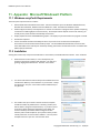
Windows arrayForth Requirements ............................................................... 58
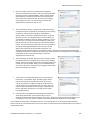
Installation .................................................................................................... 58
Identifying and Configuring COM Ports ............................................................. 60
Windows 8 Installation ...................................................................................... 62
Running arrayForth ....................................................................................... 62
12.
Appendix: Apple Mac® Platform with Windows ...................... 63
12.1
12.2
12.3
Mac Requirements ......................................................................................... 63
Installation .................................................................................................... 63
Running arrayForth ....................................................................................... 63
13.
Appendix: unix Platform including Mac OS X ........................... 63
13.1
13.1.1
13.2
Installation .................................................................................................... 63
Identifying and Configuring COM Ports ............................................................. 64
Running arrayForth ....................................................................................... 65
14.
Appendix: Native PC Platform ................................................. 65
14.1
14.2
Native arrayForth Requirements ................................................................... 65
Running arrayForth Natively ......................................................................... 65
15.
Data Book Revision History ...................................................... 67
4
Copyright© 2010-2011 GreenArrays, Inc. 10/30/13
DB004 arrayForth User's Manual
1. Introduction to this Manual
This is the primary reference manual for the arrayForth programming environment. It should be read and understood
in its entirety. In the interest of avoiding needless and often confusing redundancy, it is designed to be used in
combination with other documents.
1.1 Related Documents
The general characteristics and programming details for the F18A computers and I/O used in the GA144 are described
in a separate document; please refer to F18A Technology Reference. The boot protocols supported by the chip are
detailed in Boot Protocols for GreenArrays Chips. The configuration and electrical characteristics of the chip are
documented in G144A12 Chip Reference. The evaluation board has its own Data Book along with numerous
Application Notes. eForth and polyFORTH are likewise documented separately. The current editions of these, along
with many other relevant documents and application notes as well as the current edition of this document, may be
found on our website at http://www.greenarraychips.com . It is always advisable to ensure that you are using the
latest documents before starting work.
1.2 Status of Data Given
The data given herein are released and supported. The subject applications are under continual development; thus the
software and its documentation may be revised at any time.
Supplemental information is available on our website at http://www.greenarraychips.com/home/support. This page is
updated frequently and we recommend that you visit it regularly.
Much of the material in this manual has been compiled from contributions made by Chuck Moore and the late Jeff Fox.
Originally in the form of HTML documents, many of which were linked on our website, experience has taught us that
the material was difficult to access and study in that form. Therefore GreenArrays has replaced the HTML hierarchy
with a single, comprehensive Guide.
1.3 Documentation Conventions
1.3.1 Numbers
Numbers are written in decimal unless otherwise indicated. Hexadecimal values are indicated by explicitly writing
“hex” or by preceding the number with the lowercase letter “x”. In colorForth coding examples, hexadecimal values
are italicized and darkened.
1.3.2 Node coordinates
Each GreenArrays chip is a rectangular array of nodes, each of which is an F18 computer. By convention these arrays
are represented as seen from the top of the silicon die, which is normally the top of the chip package, oriented such
that pin 1 is in the upper left corner. Within the array, each node is identified by a three or four digit number denoting
its Cartesian coordinates within the array as yxx or yyxx with the lower left corner node always being designated as
node 000. This convention is expanded to cyyxx on the EVB001, in which case c is chip number (0 for host, 1 for
target). All functions herein accepting yxx notation also recognize cyyxx appropriately.
1.3.3 Register names
Register names in prose may be used with or without the word "register" and are usually shown in a bold font and
capitalized where necessary to avoid ambiguity, such as for example the registers T S R I A B and IO or io .
1.3.4 Bit Numbering
Binary numbers are represented as a horizontal row of bits, numbered consecutively right to left in ascending
n
significance with the least significant bit numbered zero. Thus bit n has the binary value 2 . The notation P9 means bit
9 of register P, whose binary value is x200, and T17 means the sign (high order) bit of 18-bit register T.
Copyright© 2010-2011 GreenArrays, Inc. 10/30/13
5
DB004 arrayForth User's Manual
2. Introduction to arrayForth
arrayForth is a system of software tools that may be used to develop, debug and install software for GreenArrays chips.
This system runs on several platforms that provide the Win32 API: Microsoft Windows (XP, 2000 and later), as well as
the Parallels environment on Macs and the WINE environment on Linux. Procedures and tips for installing and
managing arrayForth on each of those platforms may be found in the Appendices of this document, supplemented by
FAQ items on our website.
arrayForth is implemented as an application of the colorForth/386 system, which has a number of distinctive properties
with which this manual will acquaint you. To keep this manual simple, it is focused on working with F18 code for our
chips. Therefore it touches only peripherally on the programming of the x86 host computer.
2.1 What is colorForth?
Nearly forty years ago, Forth was developed as the world's first and, at that time, only practical, fully Integrated (and
explicitly Interactive) software Development Environment (IDE). Decades later, the industry has made attempts to
imitate such an environment, yet Forth remains the leader in both integration and interactivity.
Through a continual process of incremental change, Forth has evolved to meet new challenges in systems and
applications programming. colorForth represents one evolutionary step, seeking to maximize speed of compilation and
interpretation by minimizing the complexity of these processes. This has been accomplished by a novel approach to
source language representation.
Every programming language devised in the past half century, including classical Forth, has defined its source language
as a stream of characters. The syntactic elements of this source have been delimited by various punctuation
characters. Processing the source requires parsing the stream, one character at a time.
colorForth represents the first known experiment in eliminating the task of parsing from the acts of program
compilation and script interpretation. Instead of processing the source code one character at a time each time it is
compiled or interpreted, the identification of syntactic elements is done once, by a cooperation between the
programmer and the editor, when entering or changing the source.
Instead of storing the source as a stream of characters, the source is stored as a series of pre-parsed syntactic
elements. Each pre-parsed word is stored, in binary, in the source file; part of this binary representation is a binary tag
which indicates which of 16 syntactic elements the word represents. When source code is displayed, either on a screen
or as HTML, each syntactic element is displayed in a characteristic color. Hence the name, colorForth.
The x86 Forth system underlying arrayForth was deliberately stripped down by Chuck Moore to suit his own purposes. It
is not an ANS Forth, lacks many words and functions of classical Forth systems, and some words such as - and or have
unconventional functions. Focus on programming the F18 since the x86 system will be supplanted entirely later on.
2.2 colorForth human interface
The above characteristics of colorForth imply a new human interface using a conventional keyboard and display.
2.2.1 The Interpreter
The interpreter is the default program you will be communicating with using the keyboard and display. It accepts
words and numbers, one at a time, as you type them. Numbers are pushed onto the stack; the top few elements of the
stack are shown at the bottom of the screen. Words are executed when you type them. If a word is not found in the
dictionary, that word, followed by a question mark, is shown in the bottom right quadrant of the screen. This process
is called interpretation.
The word you type might be a simple definition such as + which replaces the top two numbers on the stack with their
sum. So for example if you had typed 5 and then 6 the stack display will show 5 6 and if you then type + the stack
display will now show 11 .
6
Copyright© 2010-2011 GreenArrays, Inc. 10/30/13
DB004 arrayForth User's Manual
The word may do a great deal more. It might compile and run an extensive utility or application, which might put up a
customized graphic or text screen, and might give you a completely different keyboard interaction while it is running.
The colorForth editor is such a program.
When any colorForth word or program you have invoked from the keyboard completes, control always returns to the
keyboard interpreter.
2.2.2 Keyboard and display
Your interaction with colorForth is accomplished by using a PC keyboard and a graphic display. As you will see,
colorForth has unique human interfaces and we are continually experimenting with improvements to them. In fact,
each colorForth application may define its own customized human interface if desired.
Situational awareness is very important in colorForth! The meaning of pressing a given button on the keyboard varies
as your actions change the system from one state to another. With this economy of motion comes the requirement that
you maintain a heightened awareness of system state from keystroke to keystroke. With only a very few exceptions,
the system state and the meanings of the keyboard buttons are apparent from a glance at the screen once you are
familiar with colorForth. Until you are, however, use caution as you would when learning any other new psychomotor
skill! For example, quickly drumming the keys in frustration would yield only laksjdf on a plain old text editor which
could easily be un-done with backspaces. However, in the colorForth editor such non-deliberate use of keys can have
truly amazing, unintended consequences, and by the time the actions have been taken you may have to audit your
whole disk to find out what you have wrought. We recommend that you keep cats and small children away from your
keyboard when colorForth is running!
Most people find that once they have mastered this new skill it works well for them, and that with the simple but
powerful set of tools in colorForth it's a pleasingly productive environment. Take your time getting accustomed to it,
and it should serve you very well.
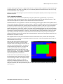
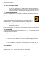
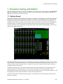
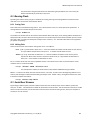
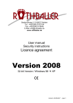
We'll start with the Interpreter interface since it's
the first thing you encounter and contains good
examples of the common display elements. Here is
what you see on booting arrayForth. The display is
composed of two major elements: The logo, with
the arrayforth label, and the interpreter's
feedback which is shown in the black areas at the
bottom of the screen. The annunciator reading qwer
is part of this feedback. The feedback is comprised
of several components, discussed below.
The first of the two major elements, the logo, may
be replaced during use of the system by other things
such as the listing of a block. The interpreter simply
displays this element, whatever it is, with the
interpreter's feedback superimposed over it. The
entire screen is refreshed, from whatever raw data
each part is based on, each time you strike a key; thus, the effects of interpreter interaction may be seen right away
when they occur.
Copyright© 2010-2011 GreenArrays, Inc. 10/30/13
7
DB004 arrayForth User's Manual
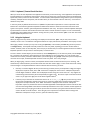
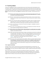
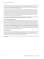
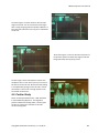
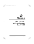
2.2.2.1 Interpreter Feedback Area
Here is an example of what you will see at the bottom of the screen when using the Interpreter:
The annunciators qwer and text are part of a keyboard / control panel hint rectangle at the lower right corner of the
screen. The word png is feedback showing the word most recently typed; it changes as you key additional characters
of a new word. The number 50389 shows the stack content; it is presently the only item on the stack. While you are
typing a word or number, the binary value of that number or encoded values(s) of the word are shown at the top of the
stack (top is on the right.)
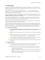
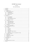
Here is what you see if you have pushed three numbers, one through three, onto the stack and then typed png to
capture the screen:
If there are more than five elements on the stack, only the top five are shown with an ellipsis (...) on the left side of
the line. Here is what you see if you have pushed six numbers, one through six, onto the stack and then typed png:
When the stack is empty, the bottom line is simply blank. If items are removed from the stack when it is empty, this
condition is indicated as follows. In this example, the stack was cleared, then the word drop was executed three
times, after which the word png was typed to capture the screen:
You may clear the stack at any time by typing the word c .
If you type a word that the interpreter cannot find in the dictionary, a question mark is appended to the display of the
most recently typed word. Here is an example resulting from trying to interpret an unknown word poobah :
The question mark is also inserted if an abort condition occurs while executing a word from the interpreter. When the
word in question causes code to be interpreted or compiled, such as load , the system attempts to place the editor's
cursor at the point of difficulty; in that case, typing e to enter the editor, as discussed later, will give you more
information.
8
Copyright© 2010-2011 GreenArrays, Inc. 10/30/13
DB004 arrayForth User's Manual
2.2.2.2 Keyboard / Control Panel Hint Area
What you see in this area depends on the application with which you are interacting. Some applications are operated
by pushing buttons on a keyboard "control panel" rather than by typing text; some examples of this are the OKAD chip
layout tools, softsim, and in fact even the Editor. In other contexts, the keyboard is being used for input of text (words,
numbers); examples are the Interpreter, and the editor when you have selected a color for text entry. Such cases are
called text entry mode.
In text entry mode, by default colorForth uses a "QWERTY" keyboard whose operation is as close as practical to the
behavior of a conventional typewriter keyboard and will be most familiar to those who have been trained as touch
typists in that system. Another, optional keyboard is available for text entry: The special "dvorak" keyboard developed
by Chuck Moore to minimize the number of buttons and amount of hand movement required. Its use is described by
an application note available from our website. During text entry mode, the annunciator qwer in the hint area shows
that the QWERTY keyboard is in use.
2.2.3 Using the Keyboard
When you begin text entry mode, the hinting area displays the annunciator qwer and you may enter words or
numbers, one at a time. The software is designed to behave as simply and naturally as feasible in the majority of cases.
After typing a word or number you may enter it using the space bar, or alternatively the enter key (some may know it
as carriage return) . The keyboard normally continues in text entry mode, expecting you to enter another word or
number. However, when in the Interpreter, the word you just entered may run another application which can redefine
keyboard operation until you return to the Interpreter, as we'll see later.
To erase a word or number before you have entered it, use the backspace key. To exit text entry mode, use the escape
key. This doesn't do anything in the Interpreter, but some applications, such as the Editor, can "call" the text entry
mode and in those cases you need to indicate when you are through by using escape. Note that at present escape will
not erase current input, and backspace will not exit the text entry word. This is easy to forget.
When you begin typing a word or number, the keyboard software needs to determine which you are entering. Like
classical Forth, colorForth allows you to define words that start with numeric digits, or even words that consist entirely
of numeric digits. The keyboard software makes its decision with the first key you strike:
if the key is a decimal digit 0..9 then you are entering a number; the key is interpreted as a digit, that digit is
displayed on top of the stack, and a num annunciator is displayed in the hint area. Subsequent keystrokes
must be digits and will be "shifted" into the displayed number using the current radix. The - key negates the
number being entered and may be used repeatedly to toggle its sign. All numeric input is restricted to 32-bit
32
values. As you type more digits, the result will be clipped modulo 2 .
If the key is any of the other 37 colorForth characters a..z !'*+ ,-./ ;?@ then you are entering a word;
the character is displayed to the left of the hint area, a Shannon-coded value consisting of that character is
displayed on the top of the stack, and a text annunciator is displayed in the hint area. Subsequent
keystrokes may be any colorForth character and will be appended to the displayed word to the left of the hint
area as well as being added to the Shannon-coded representation on the stack. If another number appears on
the stack while you are typing, this informs you that the last character you typed caused the Shannon-coded
value to exceed one 32-bit number. That's all right, but is important to know about when creating Forth
definitions to keep them unique; see 3.3.1, Syntax of colorForth, below.
Copyright© 2010-2011 GreenArrays, Inc. 10/30/13
9
DB004 arrayForth User's Manual
The behavior above allows you to just type words and numbers naturally in the great majority of cases. There are only
two situations that require you to do anything more:
Negative Numbers: The keyboard software considers the minus sign - to be an alphabetic character when it's
the first keystroke seen. Thus, simply typing -123 results in a word, not a number. To enter a negative
number, the minus sign has to be entered sometime after the first digit. So you can enter the value that was
desired above as 123- .
We could have made it go the other way, but there are too many Forth words that start with a minus, such as
the one's complement operator - , to justify this.
Words that start with a digit: You can force the keyboard software into text mode by using the grave accent
` key. This is typically on a button immediately to the left of 1 . After pressing it, the text annunciator turns
on in the hint area, and the next character entered will be taken to be the first character of a word.
Decimal and Hexadecimal
There is a persistent flag indicating whether the human interface is in decimal or hexadecimal mode.
Decimal Mode By default the human interface is in decimal mode. The stack is displayed in decimal, each
digit you key into a number is shifted into it using base 10, and the only keys accepted during number entry
are 0 through 9 and the minus sign - .
Switching Modes You may place the human interface in hexadecimal mode by pressing the F1 key. Actually
this key toggles between decimal and hexadecimal mode. The F1 key is recognized any time the hint area
shows just the qwer annunciator, or both qwer and num . It instantly sets the other mode, affecting the
stack display and subsequent digit entry. When taking text input in hexadecimal mode, the hint area shows
hex .
Hexadecimal Mode When in hexadecimal mode, the stack is displayed in unsigned hex. Each digit you key
into a number is shifted into it using base 16. The first digit of a hex number must be one of the decimal digits
0..9 , but once number entry has begun any of the hex digits 0..9 a..f or the minus sign may be entered.
Thus, to enter the hex equivalent of 255, type 0ff.
2.2.4 Message Area
A program may display a message informing you of an error or prompting some action of you. Such messages may be
displayed on the left side of the line on which the words you type are shown, as in this example:
Transitory messages disappear after you have typed a few keystrokes. Other messages may be more persistent, as
desired by the software generating them. To manually kill a message being displayed, type -msg .
10
Copyright© 2010-2011 GreenArrays, Inc. 10/30/13
DB004 arrayForth User's Manual
2.3 arrayForth User Vocabulary
This section lists resident words (those accessible after empty ) that are relevant when operating arrayForth and when
using it to program the F18. These are all x86 functions, not F18 functions; for F18 compiler syntax see section 5.3
below Unless otherwise noted, you will normally use these words at the keyboard or use them in yellow when edited
into source blocks such as scripts for the x86 utilities. Do not assume you know what a Forth word does until you have
read it in this Manual! Words and conventions necessary for programming the x86 are not listed here. x86 colorForth
programming involves unusual conventions, such as the way in which macros interact with compilation and
interpretation, and the semantics of words like if and next .
System Control
boot resets CPU sending it back to
the BIOS. Native only.
warm restarts the kernel, emptying
dictionary and interpreting
block 18.
c clears the stack, also corrects stack
underflow.
pause lets the background task run.
Practical use is to update
display.
abort terminates program
execution. The last word
interpreted from keyboard is
displayed with a question
mark. The editor is positioned
if possible to indicate the
source of the trouble. The top
stack item is discarded.
qwerty selects standard keyboard
layout and operation.
seeb toggles between visibility and
invisibility of blue words.
r? (-n) returns the number of
words on the return stack.
bye closes files and exits arrayForth.
Win32 only.
a-com (-n) returns the COM port
number for EVB001 USB port A.
a-bps (-n) returns the baud rate
desired for USB port A.
c-com (-n) returns the COM port
number for EVB001 USB port C.
c-bps (-n) returns the baud rate
desired for USB port C.
-msg
stops any active display in
the message area.
named (_) sets an ASCII pathname
in fnam for use by utilities.
The pathname is a single word
that may be up to 79
characters long. From the
keyboard the word will be
yellow; in source code it should
be white. Character
transformations are made from
cF {;'+@?*} to ASCII {:"=<>}
and space.
Words Usable in Blue
cr starts a new line in display.
br double spaced break in display.
-cr prevents new line on next red
word.
indent starts a new line indented
three spaces.
Interpreter Control
Dictionary Management
load (b) interprets block b ,
normally an even number.
mark saves the present state of the
dictionary for later restoration
by empty .
loads (bn) interprets n
consecutive source blocks
starting with block b .
empty restores the dictionary to the
most recent mark .
thru (f l) interprets consecutive
source blocks f through and
including l .
remember a class definer. The
words in its class save the
present state of the dictionary
following their definition and
when executed restore the
dictionary to that point. Use:
reclaim remember .
here (-b) returns byte address of
next available byte in
dictionary.
h (-a) a variable whose value is
returned by here .
, (n) appends the given 32-bit
word to the dictionary.
' (_-b) tick. Returns byte address
of the definition whose name
follows. Use from keyboard or
in a block.
fill (wan) fills memory for n
words starting at a with the
value w .
move (sdn) copies n consecutive
words from word address s to
word address d.
Copyright© 2010-2011 GreenArrays, Inc. 10/30/13
finish interprets the current
editor block starting at the
editor's cursor position.
fh (i-n) "from here" used to
simplify relocation of chunks of
code including their load block;
when interpreted from a block,
returns sum of that block's
number and i . When
interpreted from keyboard,
returns sum of i and the
current editor block number.
exit causes the interpreter to stop
processing a block when it is
encountered.
orgn (-a) a variable used to
register utilities that should be
reloaded after recompile has
compiled F18 source code.
Editor - See 3 below
Mass Storage - See 4.2
11
DB004 arrayForth User's Manual
Utility Block Names
floppy (-n) Floppy disk utility.
Native only.
icons (-n) Character font editor.
audit (-n) Disk audit utility. See
section 4.2.1 below.
index (-n) Index writer. See
section 4.2.3 below.
html (-n) HTML writer. See
section 4.2.2 below.
host (-n) IDE for host chip over
port A. See 6 below.
target (-n) IDE for target chip
over port C. See 6 below.
serial (-n) IDE for use by other
applications. See 6 below.
streamer (-n) Boot stream
utility. See 8.1 below.
softsim (-n) F18 code simulator.
See 7 below.
so (-n) abbreviates softsim .
Stack and Arithmetic
Watch Out for These!
@ (a-n) fetches a word from RAM
at the given word address.
- (n-n) Not subtraction! unary
ones complement, like ANS
Forth INVERT .
! (na) stores n to RAM at word
address a.
+! (na) adds n to RAM at word
address a.
dup (a-aa) duplicates top item of
stack.
drop (a) discards top item of
stack.
nip (ab-b) discards second item
of stack.
nnc (-n) number of object bins.
and (nn-n) bitwise logical AND of
two 32-bit values.
negate (n-n) returns twos
complement of a 32-bit
number.
+ (ab-c) returns the 32-bit sum of
two 32-bit numbers.
recompile uses compile to
recompile all F18 source then
reloads the utility registered in
orgn .
* (ab-c) 32-bit product of a and
b.
autotest (n) Given host chip's
IDE port number, runs ATS
tests of the target chip using
sync boot and tests SERDES
between the chips.
12
nnx (-n) number of node columns.
swap (ab-ba) interchanges the
top two stack items.
compile compiles all active F18
source code; see 5.2 below.
selftest (n) runs IDE selftest on
a chip over the given COM port
number. SPI flash boot must
not be enabled on that chip.
Chip Configuration Words
nny (-n) number of node rows.
2/ (n-n) arithmetic right shift of a
32-bit number by one bit.
png Writes a screen shot. See
section 4.2.2 below.
+or (nn-n) bitwise INCLUSIVE OR
of two 32-bit values. Same as
ANS Forth OR .
over (ab-aba) pushes a copy of
the second item onto the stack.
Utility Effectors
dump (a) displays a specially
formatted dump starting at the
given word address.
or (nn-n) bitwise EXCLUSIVE OR
of two 32-bit values. Same as
ANS Forth XOR .
nns (-n) number of nodes/chip.
nn-n (nn-n) convert cyyxx to
linear node number on chip 0.
n-nn (n-nn) convert linear node
number to yyxx notation.
@rom (nn-n) return ROM source
load block for node given in
cyyxx notation.
/ (ab-q) 32-bit signed quotient
a/b.
*/ (nab-n) multiplies a number n
by the ratio a/b.
abs (n-n) takes absolute value of
a 32-bit signed number.
min (ab-n) returns lesser of two
32-bit signed numbers.
max (ab-n) returns greater of two
32-bit signed numbers.
v+ (vv-v) sum of 2-vectors each
consisting of 32-bit signed
components.
Copyright© 2010-2011 GreenArrays, Inc. 10/30/13
DB004 arrayForth User's Manual
3. The Editor
To invoke the editor from the interpreter, first enter a block number; let's say, 18. When you have done this, the
number 18 will appear at the top of the Interpreter's stack display. Do not attempt to edit blocks 0 through 17; these
contain binaries and listing binaries can cause the windows version to trap.
Now type edit .
You will see the source code in block 18 and the number 18 will be displayed above the editor control panel hint map
(displayed in the lower right corner of the screen) indicating that the keyboard is now serving as a control panel. The
block number is red when the editor is active, changing to grey when exiting the editor.
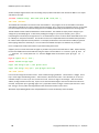
3.1 Control Panel
The editor is operated by pressing buttons on a control panel. All control panels in colorForth are built from the same
set of 27 keys; only the assignments differ. These keys are as follow:
The hint map depicts the keyboard; the
top three rows represent the red and
green areas shown at left, while the
bottom row represents the blue area.
When used as designed, left and right hands rest in the standard keyboard "home" positions with the left hand's four
fingers on the center red row and the right on the center green row. Fingers of each hand are responsible for the red
and green rows above and below the "home" positions. The thumb(s) (or right forefinger) press the qwerty keys "N",
"Spacebar", and "Alt", marked blue. The key table below names the function of each control panel key, in colored
functional groups, with hint character on top and QWERTY keycap labels in grey at the bottom of the key.
unused
(Q)
c
Change
color
(A)
a
Address
in grey
(Z)
unused
(W)
d
Find Defn
or ref
(S)
b
Blue
text
(X)
unused
(E)
f
Find next
of same
(D)
unused
(C)
w
White
text
(R)
j
Jump to
prev block
(F)
k
Copy
word
(V)
x
Cut
word
(N)
Copyright© 2010-2011 GreenArrays, Inc. 10/30/13
y
Yellow
text
(U)
l
Left
cursor
(J)
Back up
2 blocks
(m)
.
Exit
editor
(space)
r
Red
text
(I)
u
Up
cursor
(K)
m
Magenta
variable
(,)
i
Insert
word
(alt)
g
Green
text
(O)
d
Down
cursor
(L)
c
Cyan
text
(.)
*
Show src
or shadow
(P)
r
Right
cursor
(;)
+
Forward
2 blocks
(/)
13
DB004 arrayForth User's Manual
3.1.1 Exiting and re-entering the Editor
The key hinted as [.] (Exit editor) exits the Editor, returning control to the Interpreter and changing the red
block number displayed above the hint area to grey. To return to the Editor, you may type e or
enter a new block number and type edit . The editor may also be entered using the vocabulary for
finding source, described later below, or by other utilities. You can always tell that the editor is active
and that keystrokes will edit the current block when the number above the hint map is shown in red.
3.2 Navigation Commands
Navigation keys, highlighted in green in the keyboard table, move the editor from block to block and move the cursor
within a block.
3.2.1 Cursor Control
When the editor is started for the first time the cursor appears in the upper left corner of a block. If
there is text in that corner it will appear on top of the cursor. If the cursor is moved to the right it
will be placed in the first space to the right of the first word.
The cursor resembles a "Pac-Man" character poised to "munch" the word to the left when the [x]
(Cut word) key is pressed. Strings of text can be cut by repeatedly pressing or holding the [x] key
[l u d r] (Left, Up, Down, and Right cursor) keys under the fingers of the right hand move the cursor in
units of words, not characters. The cursor cannot be moved above the top of the screen but it can be
moved below the bottom of the screen. If the cursor is not visible, hold down the Up cursor key. It
should always appear eventually.
Note that the Up and Down keys do not make precise up and down movements. Instead, they move eight words to the
left or right respectively if possible.
3.2.2 Block Navigation
To begin editing some other arbitrary block, exit the editor and re-enter using edit as was described earlier. For local
navigation the Editor supplies the following:
[j] (Jump to previous block) alternates between the last two blocks that you edited with the word edit .
The traditional variable blk contains the number of the current block being edited, and is
unchanged when you exit the editor. blk 1 + contains the number of the block that was current
the last time edit was used. In addition to alternating the displayed block, the "j" key alternates
these two values in blk .
[*] (Show source or shadow) toggles between even (source) and odd (shadow) blocks while editing. Each
shadow block is intended for documentation of the source code in the corresponding even block.
Since odd numbered blocks are not normally compiled, colored words on those blocks are intended
to be comments only and may be used as desired to enhance readability.
[-] (Back up 2 blocks) and [+] (Forward 2 blocks) move the editor two blocks up or two blocks down. The
editor will not decrement the block number to be edited below 18. More advanced navigation is
supplied by the Search Utility; see below.
3.2.3 Copying Blocks
To copy an entire source block and its shadow, first display the source block that you want to copy using the editor, so
that its number is in the variable blk . Then, exit the editor; put a destination source block number on the stack, and
type copy . The first block, and its accompanying shadow, will be copied to the destination. If you want to edit the
copied block just type e as blk will now be set to the number of the destination block.
14
Copyright© 2010-2011 GreenArrays, Inc. 10/30/13
DB004 arrayForth User's Manual
3.3 Text Entry Modes
Text entry keys, highlighted in yellow in the keyboard table, select a color and put the editor and keyboard into text
entry mode. In this mode, words and numbers you type are inserted into the current block at the cursor position and
in the selected color. To determine the current state of the keyboard, look in the hint area; if you see the editor control
panel, buttons will be editor functions, whereas if you see text entry mode hints, you are entering text. To return to the
Editor from any text entry mode, use the escape key as described in section 2.2.3 above. The text entry keys are as
follow:
[w] (White text) enters comments, which may be words or small (27-bit signed) numbers in decimal or hex.
The Interpreter and Compilers ignore these words while the Editor simply displays them. Comments
may contain any of the colorForth characters.
[y] (Yellow text) enters text that will be interpreted when blocks are loaded. Text may consist of words or
numbers, and the numbers may be in decimal or hex. Words are executed, and numbers are placed
on the stack.
[g] (Green text) enters text that will be compiled when blocks are loaded. Words are compiled in the form
appropriate to the system for which compilation is being done; numbers are compiled as literals.
Within F18 code, the distinction between green and yellow words becomes narrower than that.
[c] (Cyan text) enters words only. Not relevant for F18 code, but analogous to POSTPONE in ANS Forth
when compiling x86 code.
[r] (Red text) enters a red word (labels a point in memory as a Forth definition) and switches to Green text
entry to facilitate entering the body of the new definition.
[m] (Magenta variable) enters a magenta word that, when loaded, defines a variable whose value is actually
stored in the source block itself and which is displayed in green, in decimal, when the source block is
displayed. Not relevant for F18 code.
[b] (Blue text) enters words that are ignored by the Compilers and Interpreter, but which are executed by the
source block display. Normally this is used for source code formatting but it may also be used to turn
a source block into a sort of data view. Use care in entering blue words; unless you know what you
are doing or are writing your own blue words, use only the following in blue: cr br -cr and
indent as well as the new, preferred blue words introduced in Rev 01d: , (comma) . .. ...
(one, two, and three dots), and * (star).
[a] (Address in grey) enters a special word that is only relevant in F18 code. Any short word (four characters
or less) may be used; the word itself does not matter nor is it ever displayed in its own right; instead,
it will be displayed as a faint grey, hex value in a special format. If the block is loaded by the F18
Compiler, the Compiler stores the value of its location counter at the point where the grey word
occurs in the source into the text representation of the grey word in its source block for subsequent
display by the Editor.
3.3.1 Syntax of colorForth
As stated in section 2.1 above, colorForth source is pre-parsed by cooperation between you and the editor. Your
contribution to this process is selection of the appropriate color for each word and number you type, using the above
text entry modes. In this way you will control what the Interpreter, Compilers, and Editor will do with each word when
it is encountered.
When a block is loaded, red words are the names of new defined words, like the names that follow : (colon) in
traditional Forth. Green words are words being compiled, like the traditional code between colon and semicolon.
Yellow words are interpreted like code outside colon definitions and code within square brackets inside definitions.
Magenta words are variables, and cyan words are like "postponed" words in ANS Forth (calls to macros).
Copyright© 2010-2011 GreenArrays, Inc. 10/30/13
15
DB004 arrayForth User's Manual
Numbers can be entered in green (compiled), yellow (interpreted) or white (comments), and may be entered in hex or
decimal. Hex numbers will appear in a darker green, darker yellow, or darker grey than decimal numbers, and may be
italicized when the display medium permits.
If you intend to enter a number but enter a character string that resembles a number instead, it cannot be visually
distinguished from a decimal number as it will be the same shade of yellow or green. But when you load the block
unless you have actually defined a red word or magenta variable with a name that can be confused for a number,
which is generally not a good idea in the first place, you will get a compiler error message that it did not recognize the
string (that looked like a number) as a defined name.
x86 colorForth has two wordlists (forth and macro), where the macro words behave like IMMEDIATE words in classical
Forth. It is an optimizing system so the Compiler and Interpreter make different uses of the two lists and there are
rules about which has precedence; for example, If the same word is both a macro and a forth word, the macro will
always be found when compiling (green or cyan) and the forth word will always be found when interpreting (yellow).
Macros are only relevant in x86 code. In both F18 and x86 code, the dictionary records only the first 32 bits of
identifiers (see 2.2.3, Using the Keyboard). Thus, the words atlanta atlantis and atlantic are all identical in colorForth.
A transition from green words to yellow words and back to green words causes a single word literal to be generated by
the x86 compiler. This too is irrelevant in F18 code but is mentioned only to reduce confusion when reading x86 code.
Blue words are a new feature of colorForth. They are interpreted while displaying a block. They can format the display
with cr br indent etc. or execute custom commands while viewing a screen. The word seeb in block 18 is
"see blue" and when yellow will execute at boot time and make blue words visible in the editor. If seeb in block 18 is
white then blue words will not be visible but will execute when a block is displayed. After the system has booted, you
may execute seeb at any time to toggle the display of blue words on or off. In Rev 01d, new blue words that are not
actually in the dictionary have been added for greater control over source formatting. The words . .. and ... take
exactly one, two, or three spaces whether or not they are being displayed; leading and trailing spaces are suppressed.
The word , takes exactly one space, suppressing leading spaces and starting a new line. The word * is intended for
use immediately preceding a red word; it takes exactly one space, suppressing leading and trailing spaces, and
suppresses the automatic new-line on the following red word. Because these new words suppress spaces, the cursor
behaves differently when positioned to them. As of Rev 01d, only authorized blue words are interpreted. Note that
older systems may crash when trying to display code containing these new words because they lack that protection.
3.4 Manipulating Text
The Editor has an insert buffer of finite size (18 Kbytes) for holding code that has been "cut" or "copied" for later
"pasting". The buffer is cleared by warm and, on the native system, by floppy operations. The buffer works like a
stack. The buttons that control this are:
[x] (Cut word) deletes the word to the left of the cursor and pushes it into the insert buffer stack. Successive
depressions continue deleting toward the left.
[k] (Copy word) skips over the word to the left of the cursor and pushes it into the insert buffer stack.
Successive depressions continue copying toward the left.
[i] (Insert word) pops a word from the insert buffer stack, inserting it at the cursor position and moving the
cursor to the right. Successive depressions continue laying down code so that it will appear in the
same order it had been in when cut or copied.
You may wish to change the color of a word without having to retype it, such as commenting a string of code by turning
it white, or entering source code all in green as a single text entry session and then coming back to make comments
white and things like variable references yellow. A special control panel button assists with this:
[c] (Change color) cycles the word to the left of the cursor through an appropriate cyclic sequence of colors,
based on its present color. If the word in question is not a member of a reasonable sequence, its
color is not affected by this button.
16
Copyright© 2010-2011 GreenArrays, Inc. 10/30/13
DB004 arrayForth User's Manual
3.5 Search Utility
A resident set of utility functions, integrated with the Editor, facilitates searching the source in several practical and
useful ways. When in the Interpreter, there are four words for starting a search, and one for continuing it. The words
for starting the search are find def from and literal .
When a search is started, we begin at block 18 (except in the case of from ) and scan forward looking for the
particular target. If it is not found, we remain silently in the Interpreter. If it is found, we enter the Editor with the
cursor set at (immediately to the right of) the target.
Once a search has been started, it may be continued from the point of the last target found by using the "f" control
panel key, if in the Editor, or by typing f in the Interpreter. In either case, a successful find will display a block, while
a failure to find will be as though you had done nothing at all.
When continuation is begun using the word f In the Interpreter, searching resumes at the point of last find in that
same search. When continuing using the "f" control panel button in the Editor, the search resumes at the current
cursor position in the current block, so you have more control in this case.
The searches continue up to the end of your disk image as defined by the three variables at the start of block 18. Do
not attempt to change these variables at this point in your study!
The searches automatically consider only blocks of the same sort (source or shadow) as the block in which the search
was started or continued. Thus, searches normally start with source only; they will never consider shadows unless you
force them to using the word from with an odd block number, or by using the Editor's "f" key while looking at a
shadow. To search all shadows, start a search normally, then edit block 19 and use the Editor's "f" key to continue.
3.5.1 Interpreter Search Words
find awaits a word from the keyboard and starts a new search for that word. It will find all instances of that
word as a definition (red or magenta), reference (green, yellow, blue, or cyan), or any sort of
comment.
def awaits a word from the keyboard and starts a new search for that word, as a definition (red or magenta)
only.
from takes a number from the stack for use as starting block. It then awaits a word from the keyboard and
starts a new search for that word, in any form as in find using this starting block.
literal takes a number from the stack and starts a new search for that value as a green or yellow number,
matching its numerical value (regardless of whether displayed as decimal or as hex.)
f continues the most recently started search immediately after the point at which the last target was found in
that search.
3.5.2 Editor Search Keys
"f" control panel key continues the most recently begun search, at the current editor cursor position. If the
current block is source, only source will be searched; if it is a shadow, only shadows.
"d" control panel key starts a new search based on the word immediately preceding the cursor, as follows:
If the word is a definition (red or magenta) then the new search will be for references (green,
yellow, blue, or cyan) to that word.
If the word is a reference or a white comment, then the new search will be for definitions of that
word.
If the word is a literal number, then we do not search as such but simply edit the block by that
number. Handy for use in load blocks!
Copyright© 2010-2011 GreenArrays, Inc. 10/30/13
17
DB004 arrayForth User's Manual
4. Mass Storage
arrayForth mass storage is organized in fixed length blocks of 1024 bytes (256 32-bit colorForth tokens.) By the
classical Forth convention, blocks are addressed linearly starting with zero. x86 arrayForth block space is entirely
implemented in RAM on the host system. Blocks 0 through 1439 are read from a disk or a file when the program loads,
and are only written out as you instruct. Internal block address space continues beyond 1440 for various purposes; see
section 10.4, Memory Map, for more information.
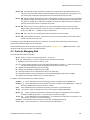
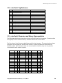
4.1 Disk Organization
The 1440 blocks of arrayForth are subdivided organizationally into twelve sections of 120 blocks each. Such a section is
called an index page, so named because 60 lines fit well on a printed page. Each release of arrayForth includes an
index listing showing the first line of each source block, delivered in a Word document named EVB001-rls-index.doc.
For the purpose of this discussion, please refer to the reference copy of the index listing for this software release in
section 10.4 below. The gross assignments for each index page are as follow:
Start
Block
0
120
240
360
480
600
720
840
960
1080
1200
1320
Purpose
Description
colorForth System
Host system words, utilities, load blocks
Code Modules
polyFORTH
SRAM cluster, Streamer. Also IDE scripts for setting DC test conditions
Virtual machine for polyFORTH system.
ATS Chip tests
Production test modules packaged for self-test use.
ATS plumbing
User
User
eForth
Modules, softsim
Compiler, ROM
I/O support for Automated Testing Subsystem (production chip test)
Available for user code
Available for user code
Virtual machine for eForth system.
Softsim and some ROM code
F18 compiler and source code for chip ROM.
Since we are of the opinion that one of the fastest and best ways to learn a new machine or system is to study others'
code, we have included a great deal of material here that you may delete if you need the space or find it of no interest.
All of the code from 360 to 1200 is potentially of this sort..
The DC test condition scripts at 300 are for study only. polyFORTH and/or eForth may be deleted if you do not plan to
use either. The ATS chip tests are provided to disclose exactly what we test in production chips; in addition tools are
included to actually run these tests on either or both chips of the EVB001 insofar as is possible without the special I/O
pin testing circuitry of the ATS test fixtures. The ATS plumbing, when complete, will be included for study as well.
We will now discuss several configuration blocks of particular interest.
Blocks [0..12[ The first twelve blocks are reserved for the native system's colorForth kernel and boot.
Blocks [12..18[ These six blocks hold the binaries for the fonts used on the colorForth display.
Block 18 This load block defines the configuration of the colorForth system and application. It is loaded on
cold or warm boot, compiling various extensions to colorForth, giving names to utilities, and loading
blocks 144, 202 and 204 to complete the definition of the arrayForth environment. The three
magenta variables at the start of this block (ns nblk nc) must never be moved. Use great caution if
altering block 18 or anything it loads since if this sequence is aborted early enough the editor is not
available to fix the problem. The yellow word qwerty in this block configures the system for
standard keyboard layout and semantics; the yellow word seeb immediately following qwerty
configures the system to display blue words. These are the recommended settings.
18
Copyright© 2010-2011 GreenArrays, Inc. 10/30/13
DB004 arrayForth User's Manual
Block 144 This load block extends colorForth to support the arrayForth tools with global variables, extra
functions, names of further utilities, resident capability to generate png files of screen graphics, and
the principal chip configuration parameters from the three blocks 190, 192, and 194.
Block 202 This block defines application tools and is maintained by GreenArrays. When you have identified
the COM port numbers corresponding to the three USB ports on the Eval Board, you will need to edit
the values for a-com and c-com to be the COM port numbers for USB ports A and C, respectively.
The baud rates for these ports are specified here as well.
Block 204 This block is yours, for any definitions you wish to make global so that they survive empty .
Before adding a word to this block, make sure it does not redefine anything else that lies under the
empty! Use def and ' (tick) to verify no redefinitions.
Block 200 This is also yours, for compiling F18 code as described in section 5.2 below.
Block 148 is the load block for softsim. At present it's necessary to alter this block to control what code is
loaded and executed in each node.
By reading the system load blocks starting with 18 in load order you will be able to follow the process of booting
arrayForth and become familiar with its components.
To find the ROM code for SPI node 705 for example, type the phrase 705 @rom list . @rom takes a node's cyyxx
coordinates and returns the number of its ROM load block.
4.2 Tools for Managing Disk
Some classical Forth words are available:
block (n-a) returns the word address of block n in memory.
list (n) displays block n as source without entering the editor control panel.
l displays the current editor block as done by list .
qx (n) displays leading comments for the index page of 60 like blocks containing n . When the audit utility
is loaded, blocks differing between working and backup areas are shown in red.
nx displays the index page following the current page.
bx displays the index page preceding the current page.
sx alternates between source and shadows for the current index page.
ox alternates between an index page based at 0 and corresponding page in backup area at abuf .
ax displays the index page in which the current editor block lies.
In addition, arrayForth provides these resident functions:
onamed (_) Sets an ASCII pathname for the working source file, by default named OkadWork.cf .
bnamed (_) Sets an ASCII pathname for the backup source file, by default named OkadBack.cf . Usage and
character transformations are the same as for named .
save writes 1440 blocks from host RAM to the working source file in compressed format.
flush synonym for save to simplify concurrent use of arrayForth alongside polyFORTH.
@back (n) reads a colorForth compressed or uncompressed image, max 1440 blocks, from the backup
source file to RAM disk at block n . On native system, reads from a floppy.
!back (n) writes 1440 blocks from host RAM block n to the backup source file with no compression. On
native system, writes to an uncompressed floppy.
wrtboot writes 18 blocks of kernel and icons to the start of a floppy (Native only).
erase (bn) stores all zeroes into n consecutive blocks starting at block b .
Copyright© 2010-2011 GreenArrays, Inc. 10/30/13
19
DB004 arrayForth User's Manual
4.2.1 Audit Utility
The auditing utility is a stand-alone set of tools that begins with empty and then compiles a temporary set of words.
Portions of the utility are designed to integrate with features already in the resident editor. It is important to
remember that the audit utility is not itself part of the editor's control panel mode, even though there are audit
functions that will leave you in the editor. With one exception you must exit the editor in order to access any of the
functions described below. How you use the utility will depend upon your needs at the time. It is appropriate for use
when merging changes made by two people, for rolling back an accidental or ill-conceived change to your working file,
or to confirm or document the complete set of changes incorporated into an internal release level.
The utility is compiled by typing audit load . To begin to examine all differences between working and backup
source files, say check all . check will decompress the backup file if required and read it into the block space at
abuf (10000). all sets up boundaries to limit your comparison to matching the 1422 blocks beginning with 18 to the
1422 blocks beginning with 10018. It begins searching from 18 stopping at the first differing block pair. It puts you in
the editor for the different working block and makes the backup block selectable with the editor "jump" function. By
holding down the jump key you can rapidly blink between the two blocks to identify the differences. To find the next
difference you press space to exit the editor and enter the word g to continue searching forward from the currently
displayed block. If there are no differing blocks remaining when typing all or g then there will be no change to the
display or to the editor mode.
Depending upon your goal for matching the working and backup files, you may choose to make changes to one or the
other image. You can use the editor's cut-copy-paste buffer to move code between the two blocks. Be careful to note
that the high order digit of the block number is correct before making any changes and verify your result often with the
jump function. If instead you are happy with the differences and simply want to overwrite one of the blocks with the
other you can exit the editor and use either take or give . Regardless of which block you are currently looking at
the word take replaces that one block (be it source or shadow) with the corresponding block that would be displayed
next using the editor jump function. In contrast the word give replaces the block you do not see with the content of
the one you are looking at. Human nature being what it is, in this case one can argue that it is safer to take than to
give.
There should not be any changes to the binaries located below block 18 unless you have made edits to the character
font table in blocks 12 to 17. To verify these binaries use the word ?bin . It will place on the stack the numbers of
any differing blocks in this range. To compress and write all of blocks 0 to 1439 out as the working source file simply
type save . This can be done at any time, not just when audit is loaded, because it is a resident definition. You can
write the image from 10000 to 11439 back to the backup source file using !back but be aware that !back does not
compress the image. colorForth does not care when booting or when using check whether an image is initially
compressed or not. Only the size of the external file is affected. In addition an uncompressed source file is easier to
export and decode using other software.
Frequently your requirements for block maintenance will be less comprehensive than when dealing with entire source
images. You might need to move a small range of blocks from one place to another, or to copy a set of blocks to be
changed or reconfigured. In the latter case you may want to audit your changes against the original block range as a
confirmation. To copy a range of blocks and shadows to another place type s d n +blocks where s is the starting
block number, d is the destination number and n is the number of source/shadow pairs to move. Do not copy
overlapping ranges from low to higher numbered blocks; you'd have better luck running with scissors.
You can use the word wipe to blank the current block or first last+1 obliterate to blank an entire range.
Obliterate is intentionally made hard to type. Exercise care in its use. Wipe and obliterate do not come with an undo
function.
You can set up a small range of blocks to run across with the audit's g word by using matching and to . Type s d
matching where s and d are the starting blocks of the two ranges you want to match, then type n to where n is the
last block number in the lower range. Typing n list v will get the compare started by examining block n for
differences. Afterward use g just as with the full range compare.
20
Copyright© 2010-2011 GreenArrays, Inc. 10/30/13
DB004 arrayForth User's Manual
4.2.2 HTML Listings
Load the HTML utility with html load . The default output filename is cf.html . You can change this name from
the command prompt if you like by typing, for example, named my.html . Then type first last+2 run , where
first and last+2 are block numbers. The result is an html file with shadow blocks on the left side and code blocks
on the right. For example, to produce a listing of an entire colorForth floppy image, type 18 1440 run . The colors
have been altered only so that the background can be white and comments black. This saves black toner or ink when
printing the listings.
4.2.3 Index Listing
Load the indexing utility with index load . The default output filename is index.txt . You can change this name
from the command prompt if you like by typing, for example, named my.txt . Then type first last+2 run ,
where first and last+2 are block numbers. An index is the top line (approximately) of each block in the range
specified. No colors are indicated, just text.
4.2.4 PNG Screen Captures
The PNG utility is resident in colorForth. You can capture the screen as a .png file at any time by typing png at the
command prompt. A png file will be created with the default name of OkadOut.gds . You will probably want to
rename this to something more appropriate, with a .png extension.
PNG is appropriate when the screen contains graphics other than a source block. The HTML utility is more suitable for
source code.
4.3 The Bonus Materials
Some of the "study material" supplied on this disk image may be executed to do useful things, as follow:
selftest (n) If the ATS materials supplied in 480 to 720 are still intact, this phrase will run all relevant ATS
tests on the chip whose IDE COM port number is given. Note that in order to test the Host chip in this
way, its no-boot jumper J26 must be installed before running selftest or the IDE will hang.
autotest (n) Again if the ATS materials are intact, this will cause the Host chip to run ATS tests on the
Target chip using the same general procedure as does the factory chip tester, by running tests
through the synchronous connection between each chip's node 300. In addition, it runs SERDES test
between Host node 701 and Target node 001, transferring a quarter million words of known unique
values each way and verifying correct receipt with line turn-arounds.
450 load Host polyFORTH IDE boot procedure. Install no boot jumper before loading this.
460 load Burns polyFORTH into flash.
1140 load Host eForth IDE boot procedure. Install no-boot jumper before loading this.
1190 load Burns eForth into flash, for example when updating eForth.
Copyright© 2010-2011 GreenArrays, Inc. 10/30/13
21
DB004 arrayForth User's Manual
5. Programming the F18
In classical Forth systems, incremental compilation is a normal mode of operation. One can load (compile) an
application, and then load another block (or body) of code that uses what had previously been compiled. That works
out fine for a single task in a single computer, but things can get trickier when programming an array of computers
each of which may have different ROM and each of which may need to get its hands upon the addresses of things in
another node. To address this set of complications while preserving effective interactivity, we have made compilation
a single monolithic operation covering all the source code currently of interest to you, and made this operation fast and
unobtrusive enough that changes may be made and immediately tested, as follows.
5.1 Source and Object Code
The F18 compiler processes a simplified language, encoded in colorForth, producing object code in a binary image of
both ROM and RAM for each node. This binary image resides in host computer memory starting at block 32768 where
there is a bin of 2048 bytes belonging to each physical node, followed by some number of virtual bins. The constant
nnc gives the number of bins for which space is allocated. By typing nnc you will see on the stack the value 432
which is 144*3; the area is sized for programs using up to two chips, with an extra 144 nodes' worth of virtual bins into
which object (for library code distributed by GreenArrays) may be stashed as noted later.
5.2 Compiling F18 Code
The word compile loads the compiler and performs a complete compilation, leaving the dictionary empty and the
object code available for further actions such as loading into nodes with the IDE or generating boot streams. When
integrated with higher level tools such as the IDE, compile is extended to reload the higher level tool after
recompiling the F18 code, with little or no disturbance in the context of your work.
Block 146 is interpreted by compile to perform this operation in several steps:
1.
ROM is compiled for every node of chip 0 so that the object area has correct data for all ROM even if you are
not compiling anything in a given node yourself.
2.
Block 150 is loaded to compile RAM code for any desired nodes. By convention, block 150 is used to load
system code provided with the software distribution, after which it loads block 200, a block reserved for your
own application code. In the distributed base, block 200 is delivered with examples for convenience, but
unlike the code loaded in block 150 this may be discarded if you don't need it.
5.3 Compiler Syntax and Semantics
If you have not read DB001, the F18A Technology Reference, please do so to familiarize yourself with the computers and
their instruction sets before reading this section. To compile code for some node, the minimum you have to write is
<cyyxx> node to select that node and, as recommended practice, <n> org to set the location counter, followed
by F18 code for that node. The full set of directives for code management is as follows:
node (nn) Given a node number in cyyxx notation, starts compilation of code tailored for that particular
node. The bin "belonging" to that node is cleared, the ROM code for that node is compiled so that its
symbols are available and correct. The location counter is set to begin compilation at location zero.
bin (nn) is used after code has been compiled for a node to stash the object code just created in some
other bin (bin number nn) than the one "belonging" to that node. Bin assignments are currently
controlled by GreenArrays; at this time we recommend you compile directly for the intended nodes
and not use bin yourself.
reclaim empties the compiler's dictionary of F18 red word definitions. Used to keep the dictionary from
overflowing and to control the scope of red F18 identifiers. It's a good idea to use reclaim before
selecting a node .
22
Copyright© 2010-2011 GreenArrays, Inc. 10/30/13
DB004 arrayForth User's Manual
Later on, when loading code into nodes with the IDE "by hand" or when specifying boot conditions for tools such as the
automated IDE loader or the stream generator, object code is identified by its bin number. By default that is simply the
node number unless you have used bin to stash the code elsewhere.
The F18 Compiler is simpler than is that of the x86; please refer to section 3.3.1 above for comparison. There are no
macros / IMMEDIATE words, there is no extensive optimizer as is present in the x86 compiler, and nothing special
happens on a yellow to green transition. Neither magenta nor cyan words are meaningful. Here is what the F18
compiler does with each color tagged word:
Yellow numbers are placed on the compiler's stack. Green numbers are compiled as 18-bit F18 literals. Both green and
yellow words are executed; the words generating F18 instructions compile opcodes into F18 memory when the
compiler encounters them. White comments are ignored. Red words fill any partial F18 instruction word with nops to
align on a word boundary and create the red word in the dictionary as a definition beginning at the current position in
F18 memory.
Although yellow words are executed when encountered, the dictionary structure of the x86 colorForth system
precludes access to host system words that are "buried" by F18 definitions. Thus the common practice of using such
words interpretively to manipulate the compiler's stack during compilation is generally not possible. For example,
words like { dup drop over + - and or 2* 2/ push pop } may not be used for this purpose because those
words generate F18 opcodes. Do not code yellow usage in F18 source other than as you find discussed here.
Due to the dictionary structure of the x86 colorForth system, many of the host computer's garden-variety Forth words
may not be used. Now, let's clarify some of the concepts referenced so far.
5.3.1 Location Counter
This is an incremental compiler. Opcodes and literals are written into an image of target node memory as they are
encountered; the only retroactive action it performs is to store into the destination fields of words containing forward
referencing jumps (such as if ) or calls ( leap ) when those forward references are resolved. The compiler keeps
track of the current position in target F18 memory with three variables:
ip (-a) address of instruction word being built
h (-a) address of the next word to store into target memory
slot (-a) next available slot number. 4 means slot 0 of a new word that has not been stored yet.
As opcodes are compiled, they are added to the instruction word being built and slot is maintained until the word is
full or until compiling an opcode that will not fit into the word. At that time the word being built is padded with .
(nop) opcodes if necessary, and a new instruction word is started at the address in h . This leaves ip pointing at the
new instruction word and h pointing at the next location in memory. The duality of ip and slot is necessary to
support multiple instructions per word; the duality of ip and h is necessary to support literals.
When literals are compiled, a @p opcode is compiled and then the literal value is stored at h , advancing h .
Alternatively you may write @p yourself and lay the following words down using yellow , (comma) or using the
compiler itself to generate an instruction word.
Jumping, calling, and memory operations address a word, not an opcode. When encountering a red word, or any other
compiler directive defining a place that may be addressed in memory, any code under construction is padded with .
(nop) opcodes if necessary to align the location counter on a word boundary. This means that in absence of explicit
control transfer opcodes, execution continues across alignment boundaries including the start of a red definition, a
technique we have learned to use often.
Location counters are incremented in the same way the hardware increments them: The low order seven bits
increment without changing the remaining bits of P . If you are generating code in RAM you will stay in RAM,
wrapping its address space at x80 in terms of the value of P and also at x40 in the sense that the hardware ignores bit
6 of the address. The compiler will also generate code for ROM, in which case the wrapping points are at x100 and xC0.
The P9 bit (x200) may be set as you wish to specify addressable destinations which will run in Extended Arithmetic
Mode.
Copyright© 2010-2011 GreenArrays, Inc. 10/30/13
23
DB004 arrayForth User's Manual
The location counter is managed using these words (all but the grey words should be written in yellow):
org (n) sets the compiler's location counter to a given address at which following code will be compiled into
the current node's bin. h and ip are initially equal but will separate after the first opcode has been
compiled.
here (-n) forces word alignment as described above and returns the current aligned location.
any grey word signals the compiler to save its location counter in the grey word's representation in the
source code. When a block containing a grey word is displayed, the location counter h at that point
in the program is shown as a two or three digit hex number; if the location counter is not word
aligned at that point, the representation xx/n indicates that slot n will be compiled next.
+cy forces word alignment then turns P9 on in the location counter. Places in memory subsequently defined
will be run in Extended Arithmetic Mode if reached by jump, call, execute or return to those places.
-cy forces word alignment then turns P9 off in the location counter.
Slot assignment is a microscopic aspect of location counter management but is important to an F18 programmer for
reasons such as optimizing forward references, aligning code on word boundaries for generation of literal instruction
words to send another node through a com port, and the like; use grey words to help you learn about this. There are
many directives that force word alignment. For slot control within a word, the following two are useful:
. compiles a nop into the next available slot, effectively skipping it.
.. forces word alignment.
5.3.2 Control Structure Directives
These are used like those in classical Forth, and should be written in green. The stack effects shown in green reflect the
host compiler's stack; those shown in prose reflect the F18 stack.
5.3.2.1 Simple Forward Transfers
Forward transfer opcodes are compiled into the next available slot and may, unless you are controlling slot allocation
yourself, be compiled into slots 0, 1 or 2 with 10, 8 or 3-bit destination fields. The stack "handle" for the unresolved
forward transfer identifies both the location and the slot of the transfer opcode. When then resolves a forward
transfer, it will abort with error message "out of range" if the transfer is unable to reach the position at which then
occurs without a larger destination field; when this occurs you must alter the code to resolve the problem.
if (-r) If T is nonzero, program flow continues; otherwise jumps to matching then .
-if (-r) If T is negative, program flow continues; otherwise jumps to matching then .
zif (-r) If R is zero, pops the return stack and program flow continues; otherwise decrements R and
jumps to matching then .
ahead (-r) jumps to matching then .
leap (-r) compiles a call to matching then .
then (r) forces word alignment and resolves a forward transfer.
5.3.2.2 Count-controlled Looping
The F18 hardware supports looping under control of a count in R . The number in R is zero-based so the number of
iterations such a loop makes is one greater than the value in R and that value will be zero during the last iteration of a
loop. No forward transfers are used by these words and there are no issues with slots; all directives that generate
backward transfers will pad the code if needed so that an opcode with the necessary size destination field may be
compiled. The directives are as follow:
24
Copyright© 2010-2011 GreenArrays, Inc. 10/30/13
DB004 arrayForth User's Manual
for (-a) (n) pushes n onto the return stack, forces word alignment and saves here to be used as a
transfer destination by the directive that ends the loop. There are times when it is useful to
decompose this directive's actions so that the pushing of the loop count and the start of the loop
itself may be separated by such things as initialization code or a red word. In this case you may write
push <other things> begin .
next (a) ends a loop with conditional transfer to the address a . If R is zero when next is executed, the
return stack is popped and program flow continues. Otherwise R is decremented by one and control
is transferred to a .
unext (a) ends a micronext loop. Since the loop occurs entirely within a single instruction word, the
address is superfluous; it is present only so that the form <n> for … unext may be written. The
micronext opcode may be compiled into any of the four slots.
5.3.2.3 Arbitrary Control Structures
As with ANS Forth, any desired control structure may be generated based on a few simple directives and flexible
semantics; see the ANS Forth standard, or more to the point see the F18 code supplied with arrayForth, for many
examples of composite control structures. The following directives are provided; the same stack notation ( a for
destinations and r for handles to forward references) is employed here. If necessary you may code swap in yellow
to affect the compiler's stack.
begin (-a) forces word alignment and saves here to be used as a transfer destination.
while (x-rx) equivalent to if swap . Typically used as a conditional exit from within a loop.
-while (x-rx) equivalent to -if swap . Typically used as a conditional exit from within a loop.
until (a) If T is nonzero, program flow continues; otherwise jumps to a . Typically used as a conditional
exit at the end of a loop.
-until (a) If T is negative, program flow continues; otherwise jumps to a . Used like until .
end (a) unconditionally jumps to a .
*next (ax-x) equivalent to swap next .
5.3.3 F18 Opcodes
The preferred opcode names, as shown in the F18A Technology Reference, each compile an opcode into a slot:
ex @p @+ @b @ !p !+ !b !
+* 2* 2/ - + and or drop dup pop over a
. push b! a!
The call opcode is compiled when a red F18 definition is used in green.
Tail optimization is performed by ; if immediately preceded by a call. In this case, the call is converted into a
jump, conserving return stack space and leading to other useful techniques.
5.3.4 Other Useful Words
io right down left up data ldata
register names, equivalent to writing address in green.
---u --l- --lu -d-- -d-u -dl- -dlu r--- r--u r-l- r-lu rd-- rd-u rdl- rdlu red
definitions for single com ports and all combinations; use in green to generate calls and jumps.
await
' (-a)
generates a call to the default multiport execute for a node based on its position in the array.
(tick) places the address of an F18 red word on the compiler's stack.
Copyright© 2010-2011 GreenArrays, Inc. 10/30/13
25
DB004 arrayForth User's Manual
5.4 Module Organization
A preliminary convention has been adopted for organizing and packaging code in a modular way, from a single node to
a cluster. This convention allows use of a single block number or name as a "handle" for the module. The first two or
more blocks of the module have fixed functions at fixed offsets. We recommend that you apply these principles in
packaging your own code. The SRAM Control Cluster Mark 1 may be studied as an example while reading the following
sections; the constant sram is the number of the first block of that module.
5.4.1 Load Block
The first block in a module is a single block which when loaded will cause all of the source code needed by a module to
be compiled. There may be arguments to this block. When completed the necessary object code will be stored in
appropriate bins (which may simply be those belonging to the nodes programmed.) If by its design a module needs to
export addresses or other identifiers, these will be available in the dictionary after it has been compiled for use in code
compiled later. In a degenerate case this block may actually contain all of the module's source code. See block sram
for an example.
5.4.1.1 Identifier Scope Control
F18 compilation is done incrementally, which means that identifiers may not be "forward referenced" symbolically.
Any identifier of any sort must be defined earlier in the compilation sequence than its references.
The scope of identifiers, including intentional or inadvertent overloading of system or compiler vocabulary, is
controlled using the remember word reclaim . In the normal case, identifiers are not exported at all, and if they are
it is usually not far in the compilation sequence. As a general practice, we recommend starting each node's code with
reclaim unless you are forced to do otherwise. Elaborate scope management structures may be implemented by
defining and using your own remember words within the scope of reclaim .
5.4.2 Boot Descriptors
The second block in a module (load block number plus two) defines the loading requirements for the module, using the
high-level language described in section 5.5.1 below. This language lists the nodes that have to be loaded, indicates
what code to load into their RAM, provides for initialization of registers and/or stacks, and provides a starting
execution address for each node. The data are recorded in tables so that the order of declaration does not need to
match the actual order in which the nodes are loaded. See block sram 2 + for an example.
5.4.3 Residual Paths
In rare cases there may be modules that need to be loaded, activated, and used during a boot sequence; SRAM and
SDRAM control clusters are examples of these. Once started it may be difficult or impossible to stop them without
resetting the chip and, in the case of SDRAM, perhaps losing the data in the device. If an application's boot process has
this sort of complication then the module in question should provide a new path for use by stream or IDE loaders that
can reach and boot all nodes remaining in the chip that are not part of the module which is running and hence now "in
the way." See block sram 4 + for an example, showing suitable paths for boot nodes 708 (async serial) and 705 (SPI
flash.)
5.4.4 Organization of Larger Projects
The appropriate structure for a larger program depends on its size and intended use. The load block should still be
first. Boot descriptors should start in the second block but may require several. If IDE operation is appropriate after
the program has been loaded, an IDE personalization with path(s) adjusted to access the remainder of the chip may be
useful. Scripts may be necessary to specify boot stream generation, IDE loading, and/or softsim setup as
appropriate. You might wish to include a script to produce HTML listings. Not all of these elements are appropriate for
every application, but if they are small you might wish to place them in this area before the actual source code. These
are merely suggestions and the recommendations may change as the system evolves.
26
Copyright© 2010-2011 GreenArrays, Inc. 10/30/13
DB004 arrayForth User's Manual
5.5 Methods of Loading Code
After code has been compiled by reference from blocks 150 or 200, it may be loaded for execution or simulation.
There are presently four basic ways in which this may be done:
Manual, interactive loading into the real chip: Use hook to build a wire to the desired node and use boot
to insert code into its RAM .
Manual, interactive loading into softsim: Use node to select a node and boot to insert code.
Automated loading into the real chip using IDE: Use the IDE loader utility to load code as directed by
interpreting Boot Descriptors.
Automated loading into the real chip using boot streams: Use the streamer utility to construct a boot
stream as directed by Boot Descriptors, then present the resulting stream to a boot node.
Automated loading into softsim: Initialize nodes as directed by Boot Descriptors.
Each of the automated methods uses the common Boot Descriptor Syntax to define what code, if any, shall be loaded
and what other initialization shall be performed before starting each node.
5.5.1 Boot Descriptor Syntax
Automated IDE and stream loading touch all nodes in a defined path starting at the relevant boot node. Automated
softsim loading touches all nodes in a chip. There is a single default treatment applying to each node touched,
regardless of which of the three methods is used. Boot Descriptors are used to specify non-default treatments using
statements that start with the word +node and continue with phrases describing the needed initialization of memory
and/or registers in the node. Nodes may appear in any order since these statements are simply filling tables for later
use. For the same reason, +node statements are cumulative in that one 100 +node phrase may set the memory
loading and starting address for node 100 while another 100 +node phrase interpreted later may override the
starting address specified earlier. The following words are used in Boot Descriptors. Their use in context is described in
following chapters on IDE, Streamer and Softsim; examples may be found by searching the distributed source code.
+node (nn) Selects table entries for node number nn, in cyyxx notation. The values in the table entries
are not changed by +node and so their values will be default unless a previous +node phrase has
been interpreted for the same node.
/ram (bin)
Loads all of RAM from the given bin in cyyxx notation. By default nothing is loaded.
/part (a n bin) Loads part of RAM, n words from the given bin, starting at address a in both the bin
and the node's RAM. This completely overrides any earlier /ram or /part phrases. It is not
possible to specify loading of various parts of RAM from various places in Rev 01e, but we plan to
permit this in a later revision.
/b (a)
Specifies an initial value for register B . Default value is the address of the IO register, as at reset.
/a (n)
Specifies an initial value for register A . Default value is unspecified, as at reset.
/io (n)
Specifies a value to be loaded into the IO register.
/stack (<n values> n) Specifies up to ten values to be pushed onto the data stack, with the rightmost
value on top. For example 30 20 10 3 /stack produces the same effect as though a program
had executed code 30 20 10 .
/p (a)
Specifies an initial value for register P . Default value is xA9 which is the routine warm in every
node's ROM. When the node is started, warm jumps to the appropriate multiport execute for the
node's position in the array. If you wish to leave the boot routine enabled in a boot node that is
touched by an automated loading procedure, specify its P value as xAA as is done by reset for such
nodes.
Copyright© 2010-2011 GreenArrays, Inc. 10/30/13
27
DB004 arrayForth User's Manual
6. Interactive Testing
Interactivity is a critical, cardinal virtue of Forth as a programming system. Turning Forth into a batch mode
programming system would be a travesty, sacrificing one of its most potent properties and setting the clock back nearly
forty years. When using Forth, a programmer becomes accustomed to having her fingers literally on the fabric of the
computer, directly manipulating its memory, registers, and other resources; exercising hardware and software without
necessarily having to write (and debug) software simply to exercise those things.
The IDE was implemented as a natural and obvious extension of the umbilical methods used with embedded Forth
systems for many decades. The method used is as non-invasive of hardware and software as is practical in this
architecture, requiring no RAM or ROM in a node being tested and touching its registers as lightly as feasible.
6.1 Terminology
Debugging is done on one or more target nodes, using an umbilical connection which will involve one or more
intermediate nodes of one to three kinds (root, wire, and end), depending on the physical location of the target node
within the chip and on the path taken to reach it. For IDE over the asynchronous interfaces of the Evaluation Board,
the root node for either chip will always be 708. The IDE may thus be used to debug code in any node except 708.
The inner load block for the asynchronous IDE is serial but this is intended to be used as a factor of other utilities. To
work with the host chip, say host load and to work with the target chip say target load after remembering to
edit a-com and c-com to identify the correct COM ports.
6.2 Using the IDE
1.
To prepare for debugging, prepare the desired source code to be compiled for RAM under control of the main
load block at 200. Initially use bins with numbers in [000..717].
2.
Examine and, if necessary, change the path lists as appropriate to make sure you can reach all the places you
need to. See examples in the code, or advanced application notes.
3.
Plug the IDE connection(s) into your host computer if you have not done so already. Make sure nothing else in
the windows environment (like dialog boxes) has any open handles for the device(s).
4.
To work with the host chip, say host load and to work with the target chip say target load after
remembering to edit a-com and c-com to identify the correct COM ports.
5.
Say talk to find and open the port, reset the chip, and download root node talker code into the chip.
6.
Display the indicator panel (say panel ) if you wish to view it (recommended!)
7.
As the indicator panel will show, you should at this point have three defined paths, one to each of the nodes
immediately adjacent to the root node.
8.
Define, tear down, and select paths as you wish, and operate on the nodes in question using the words
described below. Note: If you wish to ensure that all other bootable nodes are completely idle, begin your
activities by saying 2 <root> hook and then 2 –hook to tear that path down. The default path 2 can
reach all 143 nodes accessible to the IDE.
9.
If you wish to change the code you are downloading into any node(s), change the F18 source and say
compile which recompiles that source to binary and then re-enters the interactive environment, displaying
the block you have most recently displayed. Any paths you had wired up, and whichever you had most
recently selected, will still be in effect as you can see by displaying panel again. Recompilation does not
communicate with the chip under test.
When you are finished, you can say empty and do other things; as long as you do not say bye to your arrayForth
session, you may later load the IDE again and resume communicating with whichever paths you had left connected.
28
Copyright© 2010-2011 GreenArrays, Inc. 10/30/13
DB004 arrayForth User's Manual
6.3 Vocabulary
Words come in two classes: Those which wire, rip and select paths, and those that operate on the target node.
6.3.1 Path Routing Control
The simplest way to visualize and check the current routing situation is to simply display the panel . Node numbers
used with these words are always in the cyyxx form.
path (i) Selects path i (0, 1, or 2) so that all subsequent target operations will apply to the target node
for that path. This is necessary when more than one path leads to the same target node.
node (nn) Selects whichever path presently has node n as its target, if any. Note that it is possible to set
up more than one path to different ports of the same node; if you have done this, path will permit you
to select the desired port. Leaves a default path selected if none of them targets the node given.
hook (i nn) Wires path i to target node n after ripping out any existing wiring for that path, leaving
path i selected. If the node in question is not accessible in the route list for that path, leaves the path
set for the appropriate adjacent node as target.
-hook (i) Forces ripping out of any wiring for path i . Each node that had previously been part of this
path is left in its default warm state (multiport execute); the target node is not affected.
6.3.2 Target Operations
Each of these operations applies to the target node of the currently selected path. To help in orientation, it is good to
display the panel unless there’s something better for you to be looking at while working.
compile Recompiles both the F18 source and the arrayForth IDE source, allowing changes in the binary
images that may be loaded into nodes, or aspects of the IDE such as automated test functions (see
below). Connection to the chip is maintained, and any wiring context presently in place is preserved.
panel
upd
displays the indicator panel block.
retrieves all ten words of the data stack into the local array stak which is indexed (T, S, and the
eight elements in the F18 stack, first element being the one that would next be popped into S). panel
displays the contents of stak in two rows. First row is the deepest four elements of the F18 stack,
followed by the shallower four elements, then S and T. The shallowest element is immediately left of S;
“deeper” moves to the left on that row, then to the right on the row above, with the deepest element on
the right side of the top row. This is isomorphic with the stack array and makes its behavior clearer.
?ram
retrieves all of RAM from the selected node, updating the panel display.
?rom
retrieves all of ROM from the selected node, updating the panel display.
lit (n) removes a number from the host computer's colorForth stack, pushing it onto the data stack of the
target node and updating the stack display on the panel .
r@ (a-n) reads RAM, ROM, register or port a in the target node, pushing the data read, n onto the
colorForth stack of the host computer. Not to be confused with the F18 @/@a function. In this release,
uses and does not restore register a in the target node.
r! (n a) writes a number from colorForth data stack of the host computer into target memory (RAM,
register, port) address a . Not to be confused with the F18 !/!a function. In this release, uses and
does not restore register a in the target node.
call (a) calls, from the port, the code at address a in the target. If that code returns to the port or reestablishes the normal rest state of the target node, interactive use may continue once the code
completes. No interlocking is done so this method may also be used to start application processing which
will not admit to further port execution access. Interaction with a node actively running an application
may also be arranged but at the cost of periodically polling, as described below.
Copyright© 2010-2011 GreenArrays, Inc. 10/30/13
29
DB004 arrayForth User's Manual
boot (a n bin) loads code into the target node, starting at address a in both target and bin for n
words, from the current binary output area identified by bin . This need not be the same node as the
target.
focus forces the target to call only the port on which the current IDE path is talking to it. This remains in
effect until the target is directed to execute elsewhere.
virgin
io
rb!
forces the target to call its default multiport execution address to un-do the effects of focus .
data
up
down
ldata
@b !b ra@ ra!
rdrop rdup rover
stack display in panel.
left
right
place chip port addresses on the colorForth stack.
@a !a @+ !+ r+ r+* r2* r2/ r- rand ror
Execute single F18 instructions in target, using target's stack, and update
6.3.3 Advanced Uses
When ripping a path out, all wire and end nodes (if any) are left in their default multiport executes. This is necessary so
that, for example, paths may be crossed so long as they are not used concurrently to cause conflicts. There are
occasions, such as when starting nodes that send unsolicited code or data to other nodes, when this is not appropriate.
In those cases the following two functions are useful:
unfoc
foc
Conditions -hook to work as stated above..
Conditions -hook to leave every wire and end node focused back toward the root. This leaves the
path completely impenetrable to anyone other than the root node, and further hooking and starting of
nodes will be necessary if that path is ever to be permeable again.
The IDE is factored such that it may become a tool of other utilities. Examples are the selftest and autotest routines,
the IDE boot and flash burning tools used for eForth and polyFORTH, and even the host and target load blocks. Until
these conventions are documented here, please read the code just identified to see how it is done.
6.3.4 Working with Two Chips
The IDE may be used to interactively debug software on both chips of the Evaluation Board as though they were a
single chip with 288 nodes, using just the serial interface for the host chip.
bridge load
host .
compiles a host IDE version capable of operating on both chips. Initially it is identical with
span extends the bridge IDE to encompass both chips. In order to successfully invoke span the edge
nodes of the host chip starting with 707, proceeding to the left to 700, and downward to and including
300 must be accessible for programming; it is typically used immediately after loading bridge unless
something such as polyFORTH needs to be set up on the host chip first.. span resets the Target chip and
programs node 300 on each chip as a transparent bridge for carrying port communications between
them, using 2-wire synchronous communications. New default paths 0 and 2 are set up to cover both
chips. Thereafter, nodes 300 are dedicated to this purpose until the chips are reset.
With the port bridge built, the up ports of node 400 on each chip are logically connected as though they were a simple
COM port. Port read/write communications, such as IDE, are basically transparent across this connection except that
data transfers take 100 or more times longer, no flow control is supported, and polling of io by node 400 has limited
usefulness. Node 300 will seem to be writing when a word sent by the other chip is waiting to be read, it will seem to
be neither reading nor writing during serial data transmission in either direction, and it will seem to be reading at all
other times regardless of the state of node 400 in the other chip.
The default paths after span , shown below, facilitate full access to the Target chip with or without the polyFORTH
virtual machine present on the Host chip. Extended node numbering is supported in the form cyyxx where c is zerorelative chip number; thus nodes 000 through 717 are on the Host chip, while nodes 10000 through 10717 are on the
Target chip.
30
Copyright© 2010-2011 GreenArrays, Inc. 10/30/13
DB004 arrayForth User's Manual
6.3.5 Default IDE Paths
713.ai ao
709.ai ao
705.17
531
701 sd
700
701
600
601
Path 1 is available for general use after
host load or bridge load .
716.ai ao
708.1
715.17
703
704
705
SPI
Boot
706
707
708
Async
Boot
709
710
711
712
713
714
715
716
717
602
603
604
605
606
607
608
609
610
611
612
613
614
615
616
617
serdes
Boot
600.17
708.17
702
617.ai
617.ao
500
501
502
503
504
505
506
507
508
509
510
511
512
513
514
515
516
517
400
401
402
403
404
405
406
407
408
409
410
411
412
413
414
415
416
417
300
Sync
Boot
301
302
303
304
305
306
307
308
309
310
311
312
313
314
315
316
317
317.17
200.17
200
201
202
203
204
205
206
207
208
209
210
211
212
213
214
215
216
217
217.17
100.17
100
101
102
103
104
105
106
107
108
109
110
111
112
113
114
115
116
117
500.17
517.17
300.17
417.17
300.1
117.ai
117.ao
000
001
002
003
004
005
006
007
008
009
010
011
012
013
014
015
016
017
serdes
Boot
PH
PH
007
bus 18
001 sd
008.17
531
009
bus 18
0
Default IDE Paths after host load
713.ai ao
709.ai ao
705.17
531
701 sd
700
701
600
601
After span path 0 is generally used
for target chip...
716.ai ao
708.1
715.17
702
703
704
705
SPI
Boot
706
707
708
Async
Boot
709
710
711
712
713
714
715
716
717
602
603
604
605
606
607
608
609
610
611
612
613
614
615
616
617
serdes
Boot
600.17
708.17
2
617.ai
617.ao
500
501
502
503
504
505
506
507
508
509
510
511
512
513
514
515
516
517
400
401
402
403
404
405
406
407
408
409
410
411
412
413
414
415
416
417
300
Sync
Boot
301
302
303
304
305
306
307
308
309
310
311
312
313
314
315
316
317
317.17
200.17
200
201
202
203
204
205
206
207
208
209
210
211
212
213
214
215
216
217
217.17
100.17
100
101
102
103
104
105
106
107
108
109
110
111
112
113
114
115
116
117
500.17
517.17
300.17
417.17
300.1
117.ai
117.ao
000
001
002
003
004
005
006
007
008
009
010
011
012
013
014
015
016
017
serdes
Boot
PH
PH
007
bus 18
001 sd
008.17
531
009
bus 18
0
Default IDE Paths in Target chip after span
713.ai ao
709.ai ao
705.17
531
701 sd
700
701
708.17
716.ai ao
708.1
715.17
702
703
704
705
SPI
Boot
706
707
708
Async
Boot
709
710
711
712
713
714
715
716
717
serdes
Boot
617.ai
600.17
600
601
602
603
604
605
606
607
608
609
610
611
612
613
614
615
616
617
500.17
500
501
502
503
504
505
506
507
508
509
510
511
512
513
514
515
516
517
400
401
402
403
404
405
406
407
408
409
410
411
412
413
414
415
416
417
300
Sync
Boot
301
302
303
304
305
306
307
308
309
310
311
312
313
314
315
316
317
317.17
200.17
200
201
202
203
204
205
206
207
208
209
210
211
212
213
214
215
216
217
217.17
100.17
100
101
102
103
104
105
106
107
108
109
110
111
112
113
114
115
116
117
617.ao
517.17
300.17
... and path 2 is generally used for the
host chip. Path 1 is available for
general use. The port bridge only
requires special code in nodes 300 and
10300.
417.17
300.1
117.ai
117.ao
000
001
002
003
004
005
006
007
008
009
010
011
012
013
014
015
016
017
serdes
Boot
PH
001 sd
007
bus 18
PH
008.17
531
009
bus 18
Default IDE Paths in Host chip after span
Copyright© 2010-2011 GreenArrays, Inc. 10/30/13
0
2
31
DB004 arrayForth User's Manual
6.3.6 Automated Loading with the IDE
Block 846 in the distributed source code is a simple template for automated loading of a trivial program using the IDE.
It consists of the following elements:
host load
loader load
This phrase establishes context of a particular IDE configuration, that of the host chip on the
evaluation board, and attaches to it the loader utility. loader uses talk to reset the chip and
load IDE support code into the boot node.
0 708 hook
0 -hook
This phrase uses the default IDE path 0 to quickly force all I/O nodes to warm , thus ensuring that no
boot node is paying attention to its pins any longer.
600 +node
600 /ram
0 1 /stack
12 /p
This phrase specifies that node 600 should be loaded from its own default bin, that 0 should be
pushed onto the stack, and that the node will be started executing at location x12.
2 ship
This phrase actually loads the chip using the given IDE path. Every node in that path is touched
except the boot node itself. If +node phrases specify nodes that are not present on the given path,
they are simply ignored.
The default IDE path 2 may be used to load every node in the chip except node 708 itself.
6.3.7 Asynchronous Boot Streams
The IDE may be used to sending an arbitrary bootstream through the asynchronous serial port. Instead of using the
loader as above, the framer is invoked and a stream is created as if to be burned into flash. The only differences are
that frame is redefined to use the concatenation address of the serial boot node instead of the SPI boot node, and a
different path rooted at node 708 instead of 705 is used. Once the stream is created via boot descriptors followed by
frame , the IDE is loaded and the stream is sent to the serial boot node via send . This method is much faster than the
IDE loader.
send (a n)
Transmits a stream of n words starting at word address a from x86 memory.
For examples of use, either polyFORTH or eForth can be quickly loaded this way by typing 430 load or 1152 load
respectively.
The async boot stream can also span both host and target. Block 424 is an example of loading both chips with
polyFORTH and any other desired code. Invoking the word 2chip extends the node numbering in the same way that
span does for the IDE loader. The bridge needs to be installed explicitly though. See the code section labeled "bridge
to target" in block 426 for an example.
32
Copyright© 2010-2011 GreenArrays, Inc. 10/30/13
DB004 arrayForth User's Manual
7. Simulation Testing with Softsim
Softsim (the Software Simulator) is a program that simulates the actions of Green Arrays computers, in a single GA144
chip, at a pretty high level. It takes short cuts that allow it to run much faster than a full hardware simulation. The
following is a quick tutorial in how to use softsim.
7.1 Getting Started
After starting arrayForth, type so at the command line. You should see a colorful display. In the default layout shown
below, there are three sections which help you "drill down" into the chip. In the upper right corner is a full chip view
showing its 144 computers as an 8x18 array. On the left is an overview showing the major status and registers of a
rectangular section of the chip's nodes. This can be up to a 4x8 array as shown. The overview section is highlighted in
the full chip display. In the lower right part of the display you'll see two white numbers in the larger font which
represent "time" (the current step number) and "gap" (the number of steps between display updates). Further to the
right you'll see yellow keyboard hints.
Immediately below the full chip view there is a detailed view of a single node, called the focus node. Its node number,
000, is shown in red at the top left of this view. This node's position is shown in the full chip view with a red "X". In the
overview, the focus node's three-digit number, normally shown in grey at the upper left of each node's rectangle, is
changed to red for the focus node.
In addition to the focus node, a second node, called the other node, may be selected as well. Its detailed view may
replace the full chip view using the w key on the control panel, and the focus and other node numbers may be
exchanged with the o key on the control panel. The other node, if visible on the chip, is marked with a yellow "X" in the
full chip display, and with yellow node numbers in the overview and detailed view.
All sections of the display are animated during simulation. In the full chip view, each node is green when active and
grey when suspended.
Copyright© 2010-2011 GreenArrays, Inc. 10/30/13
33
DB004 arrayForth User's Manual
7.2 Navigating
Your right hand is the main control for what you are seeing on the display.
Now look at the keyboard hints in the lower right corner. The ludr hints mean
left, up, down, and right. The middle row's ludr keys change the current focus
node, changing the red node number in the lower right detailed view, and
moving the red markers in overview and full chip view. It's possible to move the
red marker off the screen, but you will still know where it has gone by looking at
the detailed view on the lower right. Try it and see.
Now try pressing the ludr keys in the upper row of the hints. This will move your overview window around inside the
chip. You'll see the grey node numbers change as you press these keys, and the highlighted rectangle in the full chip
view moves correspondingly. The focus and other nodes do not change when the overview is moved.
Suppose you want to watch two nodes interacting in more detail. That's why the other node exists. The middle row
ludr keys only affect the focus node in the lower right, but you can swap the focus and other nodes by pressing the o
key on the control panel. Try it. You'll see the red and yellow nodes changing roles. Now you can choose two nodes to
watch closely (use the w key to replace the full chip view with the other node's detailed view.)
In addition to the full stack display (deepest item of return stack on top, , each detailed view shows a sixteen-word
memory dump. You can navigate through the memory dump of the focus node by pressing the h (higher) and l (lower)
keys on the control panel. These move through RAM and ROM in 8-word steps.
7.3 Making it Go
Let's call the two large, white numbers in the larger font in the lower right time and gap. time is the number of steps
that have occurred since the start of the simulation. gap is the number of steps that will occur between display
updates. gap starts as 1, so the display is updated after each single step. There is another variable named fast which
can be swapped with gap if you want the display to run faster and show fewer updates. This variable can be increased
or decreased by 1 using the + or - control panel keys in the bottom row, or by 100 using the + or - keys in the top row.
The f key toggles the value of gap between fast and 1. The simulation runs very much faster when it's not updating
the display.
The g and s keys in the left hand control the progress of the simulation. Press and release the s (step) key. You should
see time change from 0 to 1 and some changes will occur in the overview as well.
When you press the g (go) key, the simulation will go on running and updating the display until you press another key.
Be careful because whatever key you press will also be take its own effect. If you just want to stop running the
simulation press the s key. The simulation will stop after one more step and nothing else will happen after that until
you press another key.
The p key is for power. It simulates a power on reset, starting the simulation over from the beginning and setting time
back to 1.
The i key runs the current instruction in the focus node to completion rather than just a single time step. It also
initiates instruction word tracking in the memory display. When tracking is active, the currently executing instruction
word is always visible in the lower 8 words of memory display. Pressing g for go will not change the state of tracking.
Pressing s for step turns tracking off, as does navigating the memory display.
When you're done with softsim or need to use the interpreter, press the . key (space bar). That returns you to the
colorforth interpreter.
34
Copyright© 2010-2011 GreenArrays, Inc. 10/30/13
DB004 arrayForth User's Manual
7.4 The Memory Dump and Decompilation
Each detailed view shows a combination memory dump and decompilation/disassembly of the code for a node, along
with a dump of both stacks. The A and B registers appear at the top next to the node number. The stacks are shown as
a single array with the return stack growing upward from R (in red) and the data stack growing downward from T and S
(in green). The memory dump shows the addresses of memory words in the left column. The instruction word or 18
bit data word follows in green. The instructions for each slot appear next, sometimes followed by the value of an
address field. While a node with detailed view is executing, the line where the current instruction word was read
appears in red. The instruction in the current slot is also in red. The other instructions remain white. The line that the
P register points to is shown in yellow. If the instruction word has been fetched from a com port the disassembly and
instruction word are shown in red above the memory dump, below the B register.
7.5 The left side display
In the array of nodes on the left each rectangle contains a list of the values of registers and opcode names representing
the current state of that node. Most of the numbers have identifying colors which turn to grey when the node is
suspended. You'd probably like to know which registers the numbers represent. Each node has twelve lines.
From top to bottom, using node 100 from the above display as an example, they are:
Row
Example
Name
1
0 @
Pins and/or
ports
2
100rdu
NODE/Abus
3
4
4fetch
15555
SLOT/OPCODE
I
5
1 rdu
M/P
6
7
8
9
10
11
15555
io
15555
15555
15555
15555
A
B
IO
R
T
S
12
@
Pins and/or
ports
Description
States of the pins are represented by 0 or 1 for low or high, yellow for
output and cyan for input. Blank when the node has no external pins.
Analog and Serdes pins are red. Pins are on the top for top nodes, bottom
for bottom nodes, and on the outside for side nodes. If the node has a
port on this side, see row 12 for its representation
The grey node number followed by the white address bus. Com port
addresses appear as three characters including r, d, l, u, or 'all' if it's a
four port address.
The white slot number is followed by the green opcode name.
White, the instruction register
The memory timer counts down in green. '-' indicates that the node is
suspended. The value of P, the program counter, follows in white.
White, 18 bit pointer register A.
White, 10 bit pointer register B.
Cyan, the write-only part of the IO register.
Red, top of return stack.
Green, top of data stack. Carry latch shown as high order .
Green, second on data stack.
When a com port is being read from or written to it is represented on the
appropriate side of the node with a "@" for reading and a "!" for writing.
The Right and Down ports are in red while the Up and Left ports are in
Magenta. Pins appear here for top and bottom edge nodes.
7.6 Getting your Code to Run
By default when softsim is loaded each node's memory (RAM and ROM) is initialized with the code most recently
compiled into the bin whose number is the same as that of the node. Again by default, register B is initialized with the
address of io and register P is initialized the same as the hardware does after reset (see chip data book.) Thus,
without any further arrangements on your part (and without the SMTM demonstration program that's started in block
1234 as delivered), the simulated chip will only run boot nodes' initialization code and soon all nodes will be
suspended. There are several general ways in which to get the chip started.
Copyright© 2010-2011 GreenArrays, Inc. 10/30/13
35
DB004 arrayForth User's Manual
The first method is closest to the actual operation of the chip. This is done by building a testbed that directly simulates
one of the four possible boot sources for the chip (SPI flash, async serial, sync serial, or SERDES) and allows the
simulator to boot a complete application just as the chip does. This can take a very long time and you will probably
prefer to use a more direct, if slightly less realistic, method.
The second method is to force one or more nodes to execute code from RAM. As indicated above, if you simply
compile code for node 105 that code will appear in node 105's simulated RAM unless you have indicated otherwise. To
run this code simply specify any desired starting address for the node. By using the boot descriptor syntax you may
fully control what code is loaded into each node, what if any register and/or stack initialization is done, and what
starting address is loaded into P . As of rev 1g, softsim will process standard Boot Descriptors (see 5.5.1 above) and
may therefore be used to simulate an application of any size using the same initial conditions as the IDE or stream
loaders create in the real chip, using the same specifications.
A third method may be used by compiling your own ROM code (simply compile code with location counter in ROM).
This method is useful for testing proposed new ROM code, including application specific ROM.
7.6.1 Softsim Example Program
For demonstration purposes block 200 compiles a short program into node 0 that will copy itself into neighbor nodes
along a predetermined path. As delivered, block 216 has a line reading 0 +node 0 /ram 0 /p . This tells softsim
that when it starts node 0 should begin executing at address 0. Softsim already has the code for bin 0 in node 0, so 0
/ram serves only as documentation. Type so to start softsim. When softsim starts for the first time node 0 will be
the focus node. It should be marked with a red X in the lower left corner of the full chip view. Notice that address 0 in
the memory dump is yellow. That means the P register contains a 0 and the program will fetch its first instruction from
there. Press the i key repeatedly and watch the program as it makes a call to address x02c. Note that pressing the i
causes the memory display to track the instruction word, so it automatically navigates to address x02c. Pressing s
instead would leave the memory display at address 0. Press the f (fast) key. The "gap" should show as 100. Press the
g (go) key and watch the module migrate from node to node.
7.6.2 Breakpoints
Each node may have one and only one breakpoint set using the word <slot> <addr> <node> break . When that
node is about to execute the instruction from addr/slot softsim will stop and paint a colored box around that node to
identify the reason for stopping. A cyan colored X will appear on the same node in the full chip view as well. Those
markers will disappear as soon as another step is taken by pressing s g or i .
The breakpoint may be removed via the command <node> -break . Breakpoints may be set or cleared at any time
interactively.
36
Copyright© 2010-2011 GreenArrays, Inc. 10/30/13
DB004 arrayForth User's Manual
7.7 Testbeds
In order to test your simulated program's interaction with the outside world you will need to make a testbed to
simulate inputs and outputs. There are two example testbeds in softsim as released, namely the SPI and Sync boot
testbeds on blocks 1230 and 1244-1246. We'll start with a simpler example to build up to what you'll need to know in
order to understand these testbeds and to create your own.
Unfortunately, testbeds are written and execute in x86 colorForth. Everywhere else in this manual we have been able to
avoid discussing the peculiarities of the x86 system's vocabulary, but here you will be using it. Follow examples and
contact customer support for assistance if needed.
The softsim engine uses vectored execution to run testbed code. An execution vector is just a variable that contains
the address of some code to be executed. If you've stored the address of a code snippet into a variable, say this for
example, then you execute the snippet with the phrase this xqt . The softsim engine has a couple of node
variables, local to a particular node, which are meant to contain the addresses of testbed code. The first is called
softbed and holds the behavior of the testbed after reset. The second is 'bed which holds the behavior to be
executed in the next time epoch. The address in softbed is copied to 'bed when softsim is initialized or restarted. If
your testbed is best defined as a state machine, you may assign the code for each major state to 'bed in each step (a
vastly superior way to mechanize state machines than case statements).
It's simple to do this. Use the arrayForth word assign to store the address of the code following assign into the
vector. Here's an example of its use. Suppose you want to simulate a fast square wave on pin 17 of node 600:
/wave softbed assign
time @ 10 / 1 and ?v p17v ! ;
600 !node /wave
Add this code to block 216 where testbeds are compiled. Run softsim and watch the pin in node 600 toggle every 10
steps. The first line defines the testbed. The second line attaches that testbed to node 600 interpretively. 600 !node
makes node 600 the current node with regard to node variables. When /wave is executed in that interpretive phrase,
the address of the code following assign is stored into softbed. When softsim is initialized (by /softsim ) that
address is copied from softbed to 'bed for node 600. Then for each step of softsim that code is executed for node
600.
The assigned code begins with a yellow time . time is a global variable which starts at 0 and is incremented for
every step of softsim. time is literally the very rough timebase for softsim (note that it does not correspond directly to
any particular unit of time but is a necessary evil in order to simulate the chip's operations in an orderly way. Each step
is on the order of TSLOT (1300 to 1650 nS at 1.8v and 22°C, see G144A12 Chip Reference "Typical Instruction Timings.")
The softsim engine allocates more than one step for longer instructions but only in integer multiples. Coupled with the
fact that each node may have a different TSLOT than its neighbors due to variations in silicon process, temperature due to
its duty cycle of operation, and accumulated aging of each node which varies by lifespan duty cycles, timing in steps
must be taken with a grain of salt. In future versions of softsim we might make a wall-clock time base for testbeds to
use and allow the step time to be specified for a given run, allowing for boundary condition testing; if you wish to do
this yourself now, do arithmetic on time before using it in the testbed. For node 600 at each step the value of time
is fetched and divided by 10. If the result is odd the pin goes high; if even the pin goes low. The word ?v is part of
softsim and turns a truth value into a voltage. If the input is 0 it remains 0; If it's non-zero (true), the value of the global
variable vdd is returned. This is 1800 by default, in units of millivolts. p17v is a node variable. It contains the
voltage on pin 17 for the current node. Since /wave is only executed for node 600 this code will set the voltage on
600.17 as a function of time; nominally a square wave whose period is roughly 28 nanoseconds. Node variables p1v
p3v and p5v also exist for nodes with two or four pins.
In the Sync boot testbed on block 1230 time is not used as the timebase. Instead a global variable named dly was
created to keep time. Also note that instead of using ?v to get a voltage value vdd @ is used in yellow. Global
variables in x86 colorForth need to be yellow but are usually followed by a green @ or ! . In this case we use a yellow
@ to fetch the value from vdd at compile time. The constant value is then compiled as a literal by the yellow to green
color transition. This is a feature of the x86 colorForth which doesn't apply to F18A code.
Copyright© 2010-2011 GreenArrays, Inc. 10/30/13
37
DB004 arrayForth User's Manual
Another example might simulate a wire connecting two pins, 600.17 and 500.17. We will assume 600.17 is an output
and 500.17 is an input.
/follower softbed assign
600 !node p17v @ 500 !node p17v ! ;
500 !node /follower
This testbed will cause 500.17 to have the same state as 600.17. Your program can set or clear 600.17 and code in
node 500 can read 500.17 from the io register and act accordingly, as if a real wire connected the two pins. A fine point
from this example is that for consistent timing this sort of testbed should usually be attached to the receiving node.
The SPI testbed in blocks 1244 and 1246 doesn't need a timebase. The testbed can simply react to changes in pin
voltage set by the F18A program. It does this by reading the voltage on a pin via, for example, p17v @ and
interpreting the state of the pin as high when VIH or VIL thresholds are crossed. In fact it will be either 1800 mv or 0 mv
for a GPIO pin in the present simulator. The situation is a bit more complicated because the testbed must pretend to
be a device which responds to the SPI protocol. For example, the SPI device must wait until the enable pin goes low
before paying attention to the clock pin. You can make such testbeds as simple or as elaborate as you require.
Here's a simple state machine that waits on a pin before taking some action.
Suppose you have a circuit that reads the signal on pin 708.17 and puts the inverted value on 708.1. Softsim already
has the word low? which sets the x86 minus flag if its input is less that 900 mv. It's used as in p17v @ low? -if
... . Note that -if is used, rather than if . The word high? below can be used as p17v @ high? -if ...
similarly.
high? v negate vdd @ + low? ;
/waiter softbed assign begin
begin 'bed assign 0 p1v ! p17v @ low? until
begin 'bed assign vdd @ p1v ! p17v @ high? until end
708 !node /waiter
In this case we change the execution vector 'bed to reflect changing conditions. The third line is a begin until
loop. It first assigns the following code to 'bed and exits. Next time this node's 'bed executes pin 1 is set to 0
millivolts and pin 17 in read. If pin 17 is not low the until returns to begin and reassigns 'bed to the same
address, ending execution for this step. If pin 17 is low the code falls through to the next line where the values are
reversed. Finally when pin 17 goes high again end jumps back to the first begin and the cycle starts over. Note
that assign not only makes the assignment but also terminates execution with a return.
With these simple building blocks more complicated devices can be simulated by custom testbeds.
38
Copyright© 2010-2011 GreenArrays, Inc. 10/30/13
DB004 arrayForth User's Manual
7.8 Interactive Testing with Softsim
Interactive softsim is intended to work very much like the interactive IDE. Skills learned in one should apply to the
other, except that this mechanism can interact with a node to which no path could be built in IDE. The remote opcodes
listed below have the same names as the words in the IDE and have the same results once you realize that they always
work on the softsim's focus node. The command node will make any node become the focus node without having to
navigate to it. Similarly the command other will make any node directly become the other node without having to
navigate to it. These words may of course be used in scripting to automate test set-up.
Note that most of the remote opcodes names start with "r" for remote, to distiguish them from the PC colorForth
words with the same names. Some of the opcodes have no PC equivalents and dispense with the "r" prefix.
The commonly used ports have names to make them easy to use. For example you can say io r@ to read the io
register of the focus node. You can also say (hex) 30000 io r! for example in a node with an io pin and see the pin
change state to a yellow 1. 0 right r! writes a 0 to the node sharing its right port with the focus node. 0 call
starts the focus node executing code at address 0 in its RAM. It runs for three steps in order to fetch the instruction
into the instruction register then leaves you in the softsim keyboard handler so you can single step or go to finish
executing that code. The word lit takes the number on top of the host stack and pushes it onto the top of the focus
node stack, just as it would in the IDE. To manually resume control panel operation, say ok h .
7.8.1 Vocabulary Reference
Host Commands
node (nn) sets node nn (yyxx
form) as the focus node.
F18 Opcodes
rdup (n-nn)
rdrop (n)
Convenient Constants
all of these
use node's own
io (-a) pushes address of io
register onto host stack.
stack.
data (-a) up data register.
other (nn) sets node nn as other.
rover (ab-aba)
call (a) makes a call to address a
in focus node and starts softsim
control panel.
rpop (-n) from return stack
ldata (-a) left data register.
rpush (n) onto return stack
right (-a) right port.
r- (n-n) bitwise invert
down (-a) down port.
boot (acn) moves c words from
address a of bin n into focus
node RAM.
rand (nn-n) bitwise AND
left (-a) left port.
ror (nn-n) bitwise exclusive OR
up (-a) up port.
lit (n) pushes n from host stack
onto focus node's data stack.
r+ (nn-n) 18-bit add, not in EAM
r@ (a-n) fetches a word from
focus node address a onto
host stack..
r2* (n-m) left shift
r! (na) stores n from host stack
to focus node address a .
break (slot addr node) sets
breakpoint for given node to
stop before executing the
opcode in the given 0-relative
slot of the instruction word at
the given address.
-break (node) clears breakpoint
for the given node.
r+* (st-st) multiply step uses A
r2/ (n-n) arith right shift
ra! (n) to register A
ra@ (-n) from register A
rb! (n) to register B
!b (n)
!a (n)
!+ (n)
@b (-n)
@a (-n)
@+ (-n)
Copyright© 2010-2011 GreenArrays, Inc. 10/30/13
39
DB004 arrayForth User's Manual
8. Preparing Boot Streams
Unless equipped with special ROM or booted using SERDES, our chips must be booted after reset by having a suitable
boot stream made available to one of its boot nodes (such as async serial, 2-wire synchronous serial, or SPI flash nodes
that are enabled for boot after reset.) A boot stream consists of one or more boot frames, which are data structures
defined and processed by the boot nodes of our chips. Each boot frame contains zero or more words of data, a starting
memory or port address at which the data are consecutively written, and a jump address to which control is
transferred by the boot node after the frame has been processed. Every boot node defines a concatenation address to
which a boot frame may jump to process another frame. After reset, a chip may boot itself from a slave device such as
SPI flash memory, or it may wait to receive boot stream(s) on one or more of its enabled interfaces. For example, a
daisy chain of subsidiary chips may be booted by a master chip using frames stored in the master's mass storage or
read from its boot device (such as an SPI flash). As another example, the serial IDE works by transmitting boot frames
into the chip under test.
8.1 The Streamer Utility
This section introduces the arrayForth tools for building boot streams from compiled source code. For more details
about boot stream composition and boot protocols, see the library of Application Notes.
Block 848 in the distributed source code is a simple template for generating a boot stream to load a trivial program and
burning that stream to SPI flash. It consists of the following elements:
empty
compile
streamer load
framer load
This phrase compiles all relevant source code and loads the environment and vocabulary for
composing SPI flash boot streams.
entire course
This phrase specifies the path to be used by the stream. entire is a default path covering the entire
GA144 from SPI boot node 705, and may be used to program any or all of the 144 nodes in the chip,
including node 705 itself. Node 705 is the last node loaded in an SPI boot stream.
600 +node
600 /ram
0 1 /stack
12 /p
This phrase specifies that node 600 should be loaded from its own default bin, that 0 should be
pushed onto the stack, and that the node will be started executing at location x12.
frame
This word builds the complete boot stream in a memory buffer. It's factorable into exec fram
where exec is the concatenation address for the SPI boot node. To make a frame for another boot
node, use the concatenation address for that node. For example, x0ae is the address for the async
serial boot node. This is the only change needed, other than the path, in order to make a boot
stream rooted in any boot node.
0 fh loaded !
nores
strlen leng !
This phrase sets up feedback to be displayed during flash burning. The current block's number is
shown, the result is set to blank, and the display is set to show the stream's length.
stream ers
This phrase erases enough flash to contain the stream. Some versions may simply erase the first 32k
bytes of flash regardless of stream length. Others may erase the entire chip, see following section.
stream 0 swap 18burn
40
Copyright© 2010-2011 GreenArrays, Inc. 10/30/13
DB004 arrayForth User's Manual
This phrase burns the generated stream into flash starting at byte address zero so that it may be
booted automatically by node 705 on chip reset.
8.2 Burning Flash
By loading the streamer utility you gain a vocabulary for erasing, burning and verifying SPI flash connected to boot
node 705 as it is connected on the Evaluation Board.
8.2.1 Erasing Flash
Flash needs to be erased before being written. This is done with the word ers which expects two parameters: A
starting address and a number of bytes to be erased.
Example: 0 8092 ers
The smallest unit of flash that can be erased on the Evaluation Board is 4K bytes, so the starting address should be on a
4K byte boundary and that's where the erasing will start. The number of bytes erased will be rounded up to the nearest
4K as well. Note: Currently the whole flash is always erased. However, ers should be called with correct arguments
for upward compatibility.
8.2.2 Writing Flash
There are two streamer commands for writing flash: burn and 18burn .
burn (s d n) writes flash in 16 bit units. s is the word address of a buffer of 16-bit words in host memory,
d is byte address of destination in flash, and n is number of 16-bit words to write.
18burn (s d n) writes flash in 18-bit units. s is the word address of a buffer in host memory with a
sequence of 18-bit values stored in consecutive 32-bit words, d is byte address of destination in
flash, and n is the number of 18-bit words to write.
burn is used for 16 bit data such as the polyFORTH nucleus or the eForth kernel. Both are virtual code for virtual
machines that run out of 16-bit SRAM.
Example: <filebuf> x8000 <filelen/2> burn
This example burns <filelen/2> words to flash at byte address x8000 from the given buffer.
18burn is used to write 18-bit data such as boot streams. The word stream returns the beginning address in host
memory and the length in 18-bit words describing the output of the framer utility. Having built a boot stream, burn
it into flash at address 0 as follows:
Example: stream 0 swap 18burn
8.3 Serial Boot Streams
By specifying a different path, rooted at a different boot node such as 708 for async serial or 300 for synchronous
serial, the framer can build streams suitable for presentation to those nodes. See the discussion of the word frame
above to create such frames; see the discussion at the end of the Interactive Testing section, above, for examples of
one way to use such streams.
Copyright© 2010-2011 GreenArrays, Inc. 10/30/13
41
DB004 arrayForth User's Manual
9. Practical Example
We have chosen a simple application to act as a practical example of how to develop and test an arrayForth program.
The only parts we will need are those included in your EVB001 evaluation kit so you should be able to reproduce our
results exactly. Our application is a simple PWM algorithm generating output to an LED.
Although simple, the PWM we will demonstrate uses a nontrivial approach. Many PWMs divide a fixed interval into a
low period and a high period such that their sum is a constant period. The output value is the ratio of high to low time.
The fixed maximum update rate derives from the period chosen. The resolution derives from the number time units
the period is divided up into, usually a power of two.
PWMs have the benefit of generating an analog value from a digital output which is linear, assuming you can feed a
perfect integrator. All PWMs force a trade-off between resolution and update rate. Usually this trade-off is fixed by
the designer for any given application by choosing an inner loop timing interval and a number of intervals in the major
period.
The algorithm we will demonstrate has several benefits over the classical design. The value presented for output is
represented as a binary fraction between 0 and 1. The precision of the output is not affected by the inner loop update
frequency which should always run as rapidly as attainable by the selected hardware. The higher the inner loop
frequency the faster any given output will reach its desired average value. The maximum output rate is determined by
period of the inner loop times the power of two represented by the least significant bit you have decided is important.
9.1 Selecting resources
For our example we will be using node 600 from the host chip because its output is easily accessible. We must move
the jumper on J39 from 1-2 to 2-3 to expose host 600.17 output. This would affect automatic MMC access but will not
interfere with access to the boot flash.
For brightness we will use 3.3v provided by one of the FTDI chips. Pin J7 is from the USB chip we will be using so it
makes a good choice. We have chosen to solder one of our LEDs between J7 and J8-3 as a com input activity light. By
connecting one of our clip leads to the anode of this LED we can pick up the 3.3v safely.
To minimize measurement interference we placed our scope between ground and J39-1. We have soldered stake pins
to one of the ground areas near the prototyping region on our EVB001 and connected scope ground there.
We will use the default IDE hook path 0 which runs the perimeter counter clockwise. To make sure that node 705 is
available right after reset be sure to keep J26 1-2 jumpered (for SPI no-boot select) whenever testing.
9.2 Wiring
See the adjacent image for a wiring example.
We twisted the clip leads together loosely and
connected one lead from the J7 USB LED anode
to the anode of our free standing test LED. The
other color clip lead runs from J39-1 to the test
LED cathode. You may choose to place one of
the resistors supplied between 3.3v and the
LED to limit current when the LED is powered.
We have chosen to leave it out in this demo as
the measured voltage is just below spec and it
simplifies the setup.
42
Copyright© 2010-2011 GreenArrays, Inc. 10/30/13
DB004 arrayForth User's Manual
We can verify our wiring and check our assumptions by simple interactive use of the IDE.
1.
Make sure the No-Boot jumper J26 is installed to avoid conflicts which might cause hangs.
2.
Simply type host load panel to load the IDE.
3.
Then type talk 0 600 hook upd to gain access to node 600 and display its stack.
4.
Switch to hex input (see 2.2.3 above) and type 20000 io r! to place the pin in strong pull down and the
LED should illuminate. A glance at the scope should show the pin to be near 0.5v due to maximum current
draw through the LED.
Try typing the following in succession and observe the voltage on your scope:
10000 io r! (weak pull-down)
30000 io r! (drive pin high)
0 io r! (high impedance)
9.3 Writing the code
The sample code we will show you has been placed in block 842. This is part of an open range of blocks that you may
use freely. To make sure that our work is automatically run through the F18 compiler we have also placed a load for it
into block 200. (You should follow the same pattern when you begin your own projects. If your project spans many
blocks it's a good practice to use the first block to load all the others and load only this first block from 200.) Blocks 200
and 842 in the arrayForth distribution contain these things to facilitate your walking through this exercise.
When picking a sequence for loading your blocks the safest one is to load each server node sometime before their
respective clients. As a matter of definition a pair of nodes have a server/client relationship if the server trusts jumping
or calling the shared port and the client feeds instructions to the same port. In practice this relationship does not
change dynamically. By loading the servers first then names defined in them are available for making instruction words
that the client can feed back to them.
Our sample is only one block and one node long. It begins with an identifying comment and then shows that it is F18
code for node 600 beginning from location zero. If this code were node-independent, you might want to leave out the
600 node phrase and specify that from the block loading this one. The code is divided into three sections, each one
in turn more aware of the others. We will describe the code in the order of its writing, as if wrapping the onion.
pwm demo for host node 600
pol checks for ide inputs and calls down
when noticed.
rtn is the return point from a down call
and is used by upd as an re-entry point.
cyc begins the actual pwm code.
upd is the ide entry point for initial
start or output update.
842 list
pwm demo 600 node 0 org
pol 000 @b 2000 dw and if
... 003 ... down b! @b push ex
rtn 006 ... io b! then 008 drop
cyc ie- 1FFFF and over . + -if
... 00C ... 20000 !b pol ;
... 00F then 10000 0 !b pol ;
upd 012 xex- drop push drop 100
... 014 pop pop iex- rtn ; 016
The core function is the three lines beginning with the comment "cyc". This code expects two stack items: an
increment value and an error accumulator. It implements the inner loop of the PWM algorithm by calculating and
sending a new value to the output pin. The hex number 20000 sets the output to strong pull down which will turn on
the LED. All other output values will not cause significant current flow. A hex value of 30000 would select strong pull
up and is not useful for this application. The hex value 10000 sets weak pull down and turns the LED off. The
commented 0 would select tristate output which also turns off the LED but permits the pad to float higher. By toggling
which of these values is commented one can rapidly compare the consequences. We will discuss how this is done in
the next section.
Copyright© 2010-2011 GreenArrays, Inc. 10/30/13
43
DB004 arrayForth User's Manual
The algorithm used is essentially an adaptation of the classical Bresenham line interpolation algorithm (or at least one
understanding of it). PWMs are good at adjusting average power by controlling the duty cycle of a current source or
sink. Power sinks such as LEDs or motors are examples of good candidates for PWM control. Because the switch to the
energy source is either full on or off they are more efficient than typical analog control methods. The following analogy
should help us to visualize this use of the algorithm.
Think of a pixel as being the smallest unit of energy that we can control; full power times the shortest time period we
can cycle the algorithm. We can map the set of all positive slopes onto the set of binary fractions between 0 and 1 by
thinking of the slope as the ratio of power on to power off time. A vertical slope is full power and a flat slope is zero
power. An infinitely thin line leaving the origin with rational ratio will pass between many pixels without striking them
dead center. There is an error term that maintains the amount by which each ideal point is missed as the line goes by.
The slope, as a binary fraction, is added to this error term. Each time there is an overflow a one is output. Each time
there is no overflow a zero is output. The remainder less than one left in the error term is always carried forward to
the next interval.
At 0.5 duty cycle there is a perfect square wave at maximum frequency. Above 0.5 the high pulses begin to
concatenate, separated by low pulses of the minimum width. Below 0.5 the low pulses concatenate between lone high
pulses. At 0.25 there is a pulse train at half the maximum frequency. At 0.125 the frequency is a quarter of maximum.
Above 0.5 for complementary slopes (where complementary is defined as 1-x and x is 0.5 to a positive power), the
signal frequency changes just as it does for those x below 0.5, except that the output signal is inverted. For slopes
below 0.5 represented by more than one 1 bit in their binary fractional forms, the output is made up from all
contributing frequencies interspersed. Because only a single overflow is possible in each cycle, each frequency is
magically merged at its own unique phase. At slopes of either 1.0 or 0.0 the error term never changes and the output
either saturates or stops.
In our implementation the hex number 20000 represents 1. The number 10000 is a half and so on. At the beginning of
"cyc" the 1ffff and removes any present overflow bits from the error term so that the next new one can be
detected. The phrase over . + -if adds the slope in S to the error term in T and tests the overflow bit. In the case
of overflow 20000 !b maximizes the output current. For the non-overflow case 10000 !b minimizes the current
flow. If our algorithm never had to represent but a single slope then at this point each of the two output phrases
would simply jump back to the cyc point. We want our code to entertain new inputs as well as to accept debugging
illumination requests so instead we jump to the command monitoring function called pol above.
When the code is running in diagnostic mode it will be loaded from an IDE "wire" coming from node 700. Examination
of the G144 quick reference poster shows that 600 and 700 are connected by their down ports. When an IDE
command is issued across the wire the first instruction is a focusing call that limits the target's program counter to only
a single port decode (in case the target had been executing a multiport fetch before). At the completion of an IDE
command, other than the call command, a return instruction completes the command and returns the target to its
original task. For an idle target node this will be a multiport execute. In our case we will be executing the PWM rather
than a port fetch. The three lines of code starting with pol serve to poll for IDE commands and if one is detected then
we turn control over to the port completely.
The first line of code fetches the IO port value, masks out the down write bit and if the result is zero (no write pending)
it jumps to the drop which restores the stack to the values expected by "cyc". If a write is pending we need to give up
control to the port but need to leave a return path to the PWM in case the intentions of the IDE are temporary. We
assume there is a focusing call to down sitting in the port and this instruction needs to be removed by reading. We
also must emulate executing this call but with a return address back to ourselves. The phrase @b push ex pulls the
call from the port, pushes it to the return stack where ex (execute) performs a co-routine jump to the address pushed
as part of the call. The new return address replaces the call address on the return stack. In this way when the IDE
completes it will return us to the io b! phrase on the last of these three lines, restoring B.
The final requirement that must be met for this demonstration code is to help the IDE in setting up and changing the
operating conditions. The IDE provides for pushing a literal item onto the target data stack but it does not support
insertion of an item to replace S in a single operation. The two lines of code called upd provide this function. The hex
literal 100 at the end of the first line is known to occupy location 13 in ram. We will code an IDE script word in the next
44
Copyright© 2010-2011 GreenArrays, Inc. 10/30/13
DB004 arrayForth User's Manual
block called seed which will store a value from the arrayForth stack at location 13 and then call upd to inject that
value into the PWM as a new slope.
As soon as the code is written we add the phrase 842 load into block 200 so that the next time we type compile
this block will be included in the compilation. Once we do so we will observe that all our grey numbers which were
initially 001 have all been modified by the F18 compile to reflect the program counter at that point in the program. If
you mistyped any names or used a name before defining it the compiler will abort with question mark appended to the
word you typed (such as compile ) to perform the compilation. If you respond with e the editor will take you to the
point in the block where the error was first detected. If all compiles well the next step is to generate some IDE script to
help us install and test the code.
9.4 The IDE script
We believe that interactive development is not merely the responsibility of some esoteric, third-party, software
development platform. We believe it is primarily a mindset. The choices and tools presented by the development
platform must simply not conflict with the proper mindset. The mindset cannot be enforced by the tools. The
following precepts can be considered to be part of the mindset.
Make small changes.
Save often.
Test every change.
Make sure all steps are repeatable (such as rebuilding everything before each test).
Choose development paths that do not preclude testing for significant intervals.
Shun tools which delay your feedback because they serve to distract you.
The reason colorForth keeps all source code memory-resident and compiles all code from pre-parsed tokens is to
encourage recompiling often. The use of scripts encourages repeatability and in colorForth you cannot even make a
definition without first committing it into a block. The arrayForth word compile supports these precepts by quickly
rebuilding all F18 object code and also by reloading whatever test environment you have configured for the current
stage in your development. To support the latter function, whenever you load testing tools they should begin with the
phrase 0 fh orgn ! which directs compile to reload that test environment as part of its job.
In block 844 you will find the test script we have built for exercising the PWM demo. The template for this script was
copied from the host block that you loaded earlier when we typed host load as part of assumption checking for
node 600 and our wiring. We encourage you to read the shadow for the host block. In our present case we have
deleted the sample definition and the canon load and added two script definitions on top the standard serial IDE
functions. We could also, if we had wanted, defined here a custom wiring path to replace the standard one but the
defaults will be adequate for such a simple program.
configure ide for demo testing.
844 list
demo ide boot empty compile serial load
***no canonical opcodes***
use the 'remote' ones
customize -canon 0 fh orgn !
a-com sport ! !nam
seed loads pwm 'rate' and re-/runs cycle.
run selects node 600 target, loads the pwm
into it and starts it with a default value.
seed n 13 r! 12 call upd ;
run talk 0 600 hook 0 64 600 boot
upd ?ram panel 0 lit 18000 seed ;
The word seed uses IDE remote commands to place its argument on top of the template literal in node 600 upd and
to restart the PWM at the upd entry point. The panel stack display is also updated so that, if you are viewing the
panel, you will see your new argument there. It is helpful when outputting a sequence to see what you put out last.
On the other hand outputting a new seed does not force panel display as this would be presumptuous and could easily
be considered a distraction.
Copyright© 2010-2011 GreenArrays, Inc. 10/30/13
45
DB004 arrayForth User's Manual
The word run forces a reset to the host chip and reloads node 600 via path 0. It displays the panel and starts the
PWM with an initial seed value of 0.75 duty cycle. Note that you would not need to use this word after a compile if
you had not made changes to the F18 code. If you had only added or changed some script function you would be good
to go.
To compile this script code for the first time and get it hooked in you type 844 load this time only. In the future
simply use compile and you will also load these definitions.
So now that your PWM and test code is loaded, it is time to power up the scope, type run and use seed to observe
the effects of different values upon the waveform and the LED. Note that although the waveform energy is a linear
function of duty cycle, your eyes do not perceive the LED intensity as linear. In a dark room you can observe the
smallest value of 1 as well as increments of 1 but as soon as it becomes significantly bright you can no longer resolve
such small differences. Your eye has some kind of a logarithmic response and responds better to powers of two or less.
Perhaps a Fibonacci ramp would be more pleasing.
9.5 Output Observations
The output waveforms shown in this section demonstrate the behavior of the PWM. We will use the term bit cell when
referring to the smallest unit of output and the word frame to refer to the period determined by the frequency
contribution of the least significant one bit in the slope value. For consistency all the waveforms shown have a frame
size of 64 bit cells. The size of our bit cell is determined by the both the algorithm and the particular speed of the node
and chip under test. For our case the bit cell time is approximately 59.5ns and the frame time comes out to
approximately 3.81us. The output values of 1/64 and 63/64 have been chosen because they are easy to sync a scope
to, because they are complementary, and because they highlight the effect and shape of a single bit cell. The last value
of 33/64 demonstrates how two frequency components merge.
The first image shows a frame of mostly zero (higher
voltage). You can see how the output rings and then floats
up gradually.
The second image zooms in on the one bit at the
perimeter of the frame. We see a strong negative going
pulse that arcs back up to a stable voltage just before
releasing.
46
Copyright© 2010-2011 GreenArrays, Inc. 10/30/13
DB004 arrayForth User's Manual
The third image is of a frame of 63 one bit cells and a
single zero bit cell. You can see how the frame begins
with a strong low going pulse that quickly stabilizes to a
firm value and ends with a short ring as it is released for
one bit cell.
The fourth image is a zoom into the frame transition of
the previous capture and shows the single zero bit cell
being replaced by the long string of ones.
The last image is of the value 33/64. It contains two
complete frames. In each frame you may count 33 one
bit cells and 31 zero bit cells. Observe that this packing
is accomplished by joining two one bit cells in each of
two locations. There is also a change of phase in the
second half of each frame.
9.6 Further Study
Please see the hybrid DAC function -dac described
in the G144A12 Chip Reference. That algorithm,
present in ROM of the Analog nodes, uses duty cycle
variation to enhance the resolution of the 9-bit
current sourcing DACs.
Copyright© 2010-2011 GreenArrays, Inc. 10/30/13
47
DB004 arrayForth User's Manual
10. Appendix: Reference Material
10.1 Glossary of Terms
This section contains concise definitions of key elements, terms, and concepts of colorForth.
Character
A member of the colorForth character set.
Compilation
The process of interpreting a stream of color tagged words and numbers from a source block in RAM.
White (comment) and Blue (display functions) are ignored as are word extensions. Yellow words and
numbers are interpreted immediately when encountered; for words, only the forth word list is
searched. When a magenta word is encountered, a variable is added to the word list ( forth must
be selected) and its value is stored in the source code where the variable's definition appears; the
current value of any active variable is visible when displaying its source. When a red word is
encountered, that word is added to the forth or macro word list depending on which was
selected most recently, and associated with the next location in the dictionary (this is done in such a
way that preceding code may continue executing across the boundary identified by the red word).
When a green word is encountered, the macro word list is searched and if found that word is
executed immediately. If not found a green word is next searched in the forth word list and if
found a call to that word is compiled into the dictionary. Cyan is used to compile a call to a macro
rather than to execute it. Grey words are ignored by the PC compiler but are updated by the F18
compiler to hold F18 memory addresses. Every colorForth program, except the kernel, is compiled
from source when needed. No "object code" or other binary image format is saved or manipulated
except that F18 binaries reside temporarily in mass storage blocks for use by softsim, the IDE, or
stream building.
Editor
The program which displays a block of colorForth source code along with a control panel for a custom
keyboard interaction, and which is the main tool for maintaining the content of source code.
Interpretation
The process of acting immediately by direction of words and numbers. When a number is
encountered it is pushed onto the stack. When a word is encountered it is executed. This is what the
Interpreter does with all input received from the keyboard. When loading a block, the interpreter
processes yellow words and numbers in the same way. When other colors are encountered, they are
handled as described above in Compilation.
Number
An integer in 32-bit, twos complement form. When used in the context of code or communications
with F18 processors, only the low order 18 bits of a number are sent to the F18, and only 18 bits are
received back.
Tag
A number which is combined with the internal binary representation of a word to identify it
syntactically.
Text Entry Mode A state of the system during which the keyboard is being used for entry of text, meaning words or
numbers. When in this mode, one of two possible keyboard behaviors is active: QWERTY, or dvorak.
Anything colorForth understands may be typed using either keyboard, but each has its own meanings
for the keyboard buttons, each has a different protocol for indicating whether a word or a number is
being entered, and each makes different use of the keyboard hint area of the display.
Word
48
When referring to memory, a word is either 32 bits (on the PC platforms) or 18 bits (on the F18
computers.) When referring to colorForth words, a word is a string of one or more characters that
are Shannon coded and tagged.
Copyright© 2010-2011 GreenArrays, Inc. 10/30/13
DB004 arrayForth User's Manual
10.2 colorForth Tag Reference
Tag
15
14
13
12
11
10
9
8
7
6
5
4
3
2
1
0
Syntax Element
Commented Number
Display Macro
Compiler Feedback
Variable
Obsolete comment form
Obsolete comment form
Comment
Interpreted Number
Compiled Macro Call
Compiled Number
Compiled Big Number
Compiled Forth Word
Define a Forth Word
Interpreted Big Number
Interpreted Forth Word
Word Extension
Color
White
Blue
Grey
Magenta
(White)
(White)
White
Yellow
Cyan
Green
Green
Green
Red
Yellow
Yellow
(color of preceding word)
10.3 colorForth Characters and Binary Representation
The following table shows three values for each of the 48 colorForth characters. Character value
zero (space) is not an actual character; instead it denotes the end of a word.
The first column is the Shannon-coded binary value for the character. The second column shows
the graphic for the character, and the third column is its internal numerical value when not
Shannon-coded. ASCII character codes are not used within colorForth; they are only used for
communication with external systems.
Shannon
0 000
0 001
0 010
0 011
0 100
0 101
0 110
0 111
1101 000
1101 001
1101 010
1101 011
1101 100
1101 101
1101 110
1101 111
chr
r
t
o
e
a
n
i
0
1
2
3
4
5
6
7
cF
0
1
2
3
4
5
6
7
24
25
26
27
28
29
30
31
Shannon
10 000
10 001
10 010
10 011
10 100
10 101
10 110
10 111
1110 000
1110 001
1110 010
1110 011
1110 100
1110 101
1110 110
1110 111
chr
s
m
c
y
l
g
f
w
8
9
j
k
.
z
/
Copyright© 2010-2011 GreenArrays, Inc. 10/30/13
cF
8
9
10
11
12
13
14
15
32
33
34
35
36
37
38
39
Shannon
1100 000
1100 001
1100 010
1100 011
1100 100
1100 101
1100 110
1100 111
1111 000
1111 001
1111 010
1111 011
1111 100
1111 101
1111 110
1111 111
chr
d
v
p
b
h
x
u
q
;
'
!
+
@
*
.
?
cF
16
17
18
19
20
21
22
23
40
41
42
43
44
45
46
47
49
DB004 arrayForth User's Manual
10.4 Memory Map
arrayForth mass storage block address space maps directly onto the active memory available for use by the system. Its
absolute memory origin varies between the Native and Win32 systems, but block 0 is always the beginning of this area
regardless of what absolute address it corresponds with. In the table below, the block numbers are absolute but the
memory addresses are all relative to the origin of block 0.
50
Block
number
32768
Relative
byte addr
x2000000
Size in bytes
29000
10000
2900
2880
1440
18
12
0
x1C52000
x9C4000
x2D5000
x2D0000
x168000
x4800
x3000
0
3,768k
19,000k
7,100k
20k
1440k
1440-18k
6k
12k
864k
Usage
Object code area, two blocks per bin.
144 bins (0000..0717) for host chip;
144 bins (0800..1517) for target chip;
144 bins (1600..2317) for GreenArrays tools and utilities.
Buffer for source compression/decompression functions.
Compare area for audit utility, otherwise available.
Initial value of here after boot. Program text and data.
List of forth words, 8 bytes per word, limit of 2560
Extended source code area, unused at present
Source code (from OkadWork.cf on Win32 systems)
Icons table for character set.
Native system kernel.
Copyright© 2010-2011 GreenArrays, Inc. 10/30/13
DB004 arrayForth User's Manual
10.5 Index Listing for Rev 02a
18
20
22
24
26
28
30
32
34
36
38
40
42
44
46
48
50
52
54
56
58
60
62
64
66
68
70
72
74
76
78
80
82
84
86
88
90
92
94
96
98
100
102
104
106
108
110
112
114
116
118
ns 625 nblk 1440 nc 18 144a12 02b 42c/22a
macros macro
- macros
- compiled macros
colors etc
decompress empt 32 load
- more macro uses ebx
native system dependencies macro
windows system dependencies
- clock
native clock macro pentium timer
logo and watermark
miscellaneous
dump empty x 75751424 y -79635296
timing tmt 286630312 tmn -162350156 tmp 642452
floppy utility empty hd 1 ad 152338
icons empty macro
- control panel
serial 3f8 2e8 1050 macro
word search macro
- more fmask -16 fnn -1794220780
editor recolor 8 display = < 13 display = !
blue words >blu 255 0 >blu !
- blue and grey
convert cf character to/from ascii
pathname input -nat 72 load set1
index empty -nat
- more
qx >qxc 271547945 qb 120 82 load
- formatting ws 271547561
resident compress 86 load
- more macro uses ebx
display text macro
disk audit utility empty 30 load bias 0
- compare cvec 271556556
improved stack display nr 6
show bin occupancy empty compile
ide native async 0 fh orgn ! macro
- umbilical 3F8 serial 60 load
ide windows async 0 fh orgn ! macro
- umbilical sport 3 1 sport !
- com port management
- node 708 boot frames
Copyright© 2010-2011 GreenArrays, Inc. 10/30/13
120
122
124
126
128
130
132
134
136
138
140
142
144
146
148
150
152
154
156
158
160
162
164
166
168
170
172
174
176
178
180
182
184
186
188
190
192
194
196
198
200
202
204
206
208
210
212
214
216
218
220
222
224
226
228
230
232
234
236
238
- node 708 paths
- boot target adjacent "wall 271582744
- stream components "pth 67896348
- umbilical plumbing "foc 271580178
- routing control
- target anywhere
- remote instructions
indicator panel 135 load node stack / upd
- tester
- canonical words
- ide ats support
- all-nodes tester
arrayforth tm and okad tools and designs
f18 compiler empty c
f18 software simulator empty compile
test code for chip reclaim
redact okad disk audit load
c-a-c - ascii for gds only! macro
big letters macro
big clock empty 40 load 156 load
compare empty 30 load
png empty -nat w 1024 hh 768 d 1
- pallettes
- crc ad1 14840 ad2 50699 macro
- lz77 macro
cf-html empty -nat
- generate html details
- translate text and numbers pos 0 --bs 1
- translate cf token details
- translate cf tokens
- stylesheet details and file output
- internal stylesheet
chip configuration g144a12
- pads, ports and resets
- node types
user f18 code reclaim
ga application tools
- user application tools
evb001 host chip ide empty compile
evb001 target chip ide empty compile
ide based loader pth 2 root 708 talk
- configuration tables com 116
- routing "rte 67896840
softsim configuration
evb001 bridge 2-chip ide empty compile
- paths
- build port bridge
51
DB004 arrayForth User's Manual
240
242
244
246
248
250
252
254
256
258
260
262
264
266
268
270
272
274
276
278
280
282
284
286
288
290
292
294
296
298
300
302
304
306
308
310
312
314
316
318
320
322
324
326
328
330
332
334
336
338
340
342
344
346
348
350
352
354
356
358
framer overlay
- framer com 131
- framer "pth 67898173 "wall 271590019
- framer
- framer
ers flash erase function overlay
flash writer 18 bit overlay
- code for flash writer
exercising flash 20 org
writing flash 8 bits overlay
code for reading and writing flash 8 bits
default flash path for whole chip
sram cluster mk1
- load descriptor
- residual paths
sram.16 address-bus 9 node
- control-pins 8 node host
- data-bus 7 node host
- interface 107 node 0 org
- user node 106, 108, or 207.
- degenerate sram 107 node 0 org
streamer
flash utilties feedback
- flash utilities feedback
pf to flash
speedup spi boot 705 node 0 org
stream to file named stream.bin
dc characterization code added march 2011.
custom test code 609 node 0 org
set all high z for leakage test talk
set all weak pd for wpd test talk
set all high for several tests talk
set all low for several tests talk
t04 all node access talk
vt=- node 217 compile talk 2 217 hook upd
vt=- node 517 compile talk 0 517 hook upd
vt n7/8 compile talk
vt n9/8 compile talk
t10 schmitt power talk
t11 suspended power talk
study single node = boot power talk
t12a boot power talk
t12b boot pwr = drop same talk
t12c boot pwr = drop alternating talk
t12d boot pwr = greg test talk
t12e boot pwr = unext talk
sram test bd quiet i/o talk
study single node w/boot suspended talk
705 unext w/boot suspended talk
instr timing code 610 node 0 org
study instr timing talk
mark mem test all nodes
mark burn on one weak node
52
360
362
364
366
368
370
372
374
376
378
380
382
384
386
388
390
392
394
396
398
400
402
404
406
408
410
412
414
416
418
420
422
424
426
428
430
432
434
436
438
440
442
444
446
448
450
452
454
456
458
460
462
464
466
468
470
472
474
476
478
polyforth virtual machine reclaim
- load descriptors
-- virtual machine
-- serial terminal
-- additional i/o
- host ide with pf running empty compile
-- residual paths
pf.16 stack 0 org
- stack cont"d
pf.16 bitsy 0 org
- bitsy cont"d
stack down bxxx 6 node 0 org
stack up axxx 206 node 0 org
bitsy down fxxx 5 node 0 org
bitsy up exxx 205 node 0 org
serial transmit 100 node 0 org
- receive 200 node 28 org
- interface 104 node 20 org
generate ganglia
- ganglion template
- snorkel reclaim 207 node 0 org
spi flash sst25wf080 reclaim 705 node 0 org
minimal spi reclaim 705 node 0 org
2 chip async bootstream demo
- generate stream
async pf bootstream with bridge
- generate pf stream
-- path both chips
install pf via async bootstream
- generate pf stream
-- read pf nucleus ft 0 chr 9216 0 chr !
-- load polyforth nucleus
- sram loader nodes
- spi flash 8 bits 705 node 0 org host
polyforth ide boot host bridge load
- custom ide paths
- sram user code from nodes 106, 108, 207
- ph0 sram setup
install pf in flash
- burn pf nucleus
-- read pf nucleus ft 0 chr 9216
- generate pf stream
-- load polyforth nucleus
Copyright© 2010-2011 GreenArrays, Inc. 10/30/13
DB004 arrayForth User's Manual
480
482
484
486
488
490
492
494
496
498
500
502
504
506
508
510
512
514
516
518
520
522
524
526
528
530
532
534
536
538
540
542
544
546
548
550
552
554
556
558
560
562
564
566
568
570
572
574
576
578
580
582
584
586
588
590
592
594
596
598
g144a12 ats test components
2000 port tests
2001 port tests with 2
2002 extensive ram test jeff
2003 testing t and s
2004 testing t and r
2005 testing stack registers
2006 testing return stack registers
2007 mark ram test 200 node
2008 mark r d stack test
2009 = a shift test
2010 t s a and r data path tests
2011 gpio pin test
2012 mark d stack test
2013 io data path tests
2014 set/clear carry test
2015 mark <p test
2016 test i-ad and r-ad data paths
2017 rom checksum
2100 parallel port pin test
2101 mark <b !b test
2102 mark t to b reg test
2103 mark port to i-reg test
2104 mark port to i-reg-bit-short test
2105 mark port to i-reg-bit-short test
2106 mark port to i-reg-bit-short test
2107 mark port to i-reg-bit-short test
2108 mark port to i-reg-bit-short test
2109 mark port to i-reg-bit-short test
2110 mark prp-call test
2111 mark prp-ex test
2112 serdes 001 slave test
2113 serdes 701 master test
2114 basic analog checks
2115 mark 2 test
2116 mark 2/ test
2117 mark 2/ test
2200 tst= mark testing =
2201 mark r d stack test v2
2202 mark d stack test v2
2203 mark test = v2
2204 mark testing and
2205 mark test and
2206 mark testing or
2207 mark test or v2
2208 mark test -
Copyright© 2010-2011 GreenArrays, Inc. 10/30/13
600
602
604
606
608
610
612
614
616
618
620
622
624
626
628
630
632
634
636
638
640
642
644
646
648
650
652
654
656
658
660
662
664
666
668
670
672
674
676
678
680
682
684
686
688
690
692
694
696
698
700
702
704
706
708
710
712
714
716
718
res for more ats test pkgs ---
1900 ats analog
1901 ats sync boot master
1902 boot frame for master testing
1903 boot frame for master testing
1904 ats sync bridge
1905 uut bridge debug
1906 tester bridge debug
bridge loader
1400
1401
1402
1403
ats
ats
ats
ats
cs
cs
cs
cs
master0 n108
wire
digital
analog
xxxx smtm mem-random converted
tb001 ide pretest empty compile serial load
- pre powerup tests 662 list
- power opens and shorts
- results
- port bridge
tb001 ide creepers empty serial load
- all tests
- multichip ide
-- paths 0,1
-- paths 1
-- paths 1a
- control lines
- all-nodes runner
- incremental runner
- build table of valid io w/r bits
- build table of rom checksums
- results
- runner for 911 pin test
- runner for 917 rom checksum
- runner for 2113 serdes test
- runner for 2114 analog test
selftest a chip, port on stack empty stp !
- paths
ats target test given host port empty stp !
- paths
- build port bridge
- runner for 2113 serdes test
53
DB004 arrayForth User's Manual
720
722
724
726
728
730
732
734
736
738
740
742
744
746
748
750
752
754
756
758
760
762
764
766
768
770
772
774
776
778
780
782
784
786
788
790
792
794
796
798
800
802
804
806
808
810
812
814
816
818
820
822
824
826
828
830
832
834
836
838
10baset ethernet cluster mk1
- load descriptor
- residual paths exit
- tx load descriptor
417 tx osc 788 load exit 417 node 0 org
317/316 tx pin 317 node 0 org
315 tx mux 315 node
115/215 autonegot 215 node 0 org
314 tx framing 314 node 0 org
214 tx delay 214 node 0 org reclaim
114 tx crc reclaim 114 node 0 org =cy
113 tx unpack 113 node 0 org reclaim
112 tx wire 112 node 0 org reclaim
108 sram master reclaim host host"s memory...
109 dma nexus slave 109 node 0 org
110 dma nexus 110 node 0 org
110 continued
111 tx ctl 111 node 0 org
010 rx ctl 10 node 0 org
011 rx byteswap 11 node 0 org reclaim
012 rx pack 12 node 0 org reclaim
013 rx crc reclaim 13 node 0 org =cy
014 rx frame 14 node 0 org reclaim
015 rx parse 15 node 0 org reclaim
016 rx timing 16 node 0 org
217/216/116 rx active pull-down
117/017 rx pin 117 node 0 org reclaim
517 tx osc monitor 517 node reclaim
516 tx osc agent 516 node 0 org =cy
ether test ide empty compile
flakey 517 tx osc monitor 517 node reclaim
flakey 516 tx osc agent 516 node 0 org =cy
417 tx osc 417 node 2 org
54
840
842
844
846
848
850
852
854
856
858
860
862
864
866
868
870
872
874
876
878
880
882
884
886
888
890
892
894
896
898
900
902
904
906
908
910
912
914
916
918
920
922
924
926
928
930
932
934
936
938
940
942
944
946
948
950
952
954
956
958
uncommitted/user code
pwm demo 600 node 0 org
demo ide boot empty compile serial load
loader template host load loader load
framer template empty
framer host flash to target boot
framer bridge paths
- app boot descriptors
carry time 308 node reclaim 0 org
0xx-108 rx sram logging
gpio rx pin 217 node 0 org
sha-256 scheduler 101 node 0 org =cy
sha-256 scheduler 102 node 0 org =cy
data source 100 node 0 org
data sink 201 node 0 org
data sink 1 node 0 org
softsim setup
sha-256 scheduler 101 node 0 org =cy
ethernet calibration code
ether calib ide boot host load loader load
- residual paths
417 send link pulses 417 node 0 org
217/317 rx pin 217 node 0 org
117/217/317 rx pin 117 node 0 org
117/217/317 rx timing 117 node 0 org
- testloop load descriptor
015..517 rx display
rx timing 217 node 0 org
test rx in 300 400 node 0 org
rx timing 2 217 node 0 org
417 orig tx osc 417 node 0 org
Copyright© 2010-2011 GreenArrays, Inc. 10/30/13
DB004 arrayForth User's Manual
960
962
964
966
968
970
972
974
976
978
980
982
984
986
988
990
992
994
996
998
1000
1002
1004
1006
1008
1010
1012
1014
1016
1018
1020
1022
1024
1026
1028
1030
1032
1034
1036
1038
1040
1042
1044
1046
1048
1050
1052
1054
1056
1058
1060
1062
1064
1066
1068
1070
1072
1074
1076
1078
an012 ti sensortag reclaim
- load descriptors
-- code
an012 ide boot bridge load loader load
- custom ide paths
install pf in flash
- generate pf stream
-- load polyforth nucleus
715 xtal osc reclaim 10715 node 0 org
717 hub timing reclaim 10717 node 0 org
713 light sensor reclaim 10713 node 0 org
709 i2c timing reclaim 10709 node 0 org
708 slow i2c reclaim 10708 node 0 org
705 spi boot reclaim 10705 node 0 org
617 fake hub reclaim 10617 node 0 org
more tests
Copyright© 2010-2011 GreenArrays, Inc. 10/30/13
1080
1082
1084
1086
1088
1090
1092
1094
1096
1098
1100
1102
1104
1106
1108
1110
1112
1114
1116
1118
1120
1122
1124
1126
1128
1130
1132
1134
1136
1138
1140
1142
1144
1146
1148
1150
1152
1154
1156
1158
1160
1162
1164
1166
1168
1170
1172
1174
1176
1178
1180
1182
1184
1186
1188
1190
1192
1194
1196
1198
compile 16-bit eforth virtual machine
- e4vm16 stack 8xxx-9xxx
--- more stack
-- stack up bud axxx 206 node 20 org
-- stack down bud bxxx 6 node 20 org
- e4vm16 bitsy cxxx 105 node 0 org
--- more bitsy
-- bitsy right bud dxxx 104 node host
-- bitsy up bud exxx 205 node 20 org
-- bitsy down bud fxxx 5 node 20 org
- flash to sram pipe host
-- head/pipe nodes take two parameters!
-- tail / starter node takes three parameters!
-- eforth flash interface 0 org
- siobus16 wire nodes host
-- generic siobus wire 30 org
-- tx plug node host
-- rx plug node 0 org
--- more rx
-- 1-pin plug node 20 org
-- dummy flash controller plug 0 org
eforth ide host load
- ide build paths
- read 16-bit eforth.bin file
- ide access sram16 from nodes 108 and 207
- ide access term16 from 104 , flash from 706
install eforth via async bootstream
- generate eforth stream
-- read eforth kernel ft 0
-- load eforth kernel
eforth chip builder
- build sram16 using srampath
- build siobus wires and plugs using e4path
- build e4vm16 nodes using e4path
- sram loader nodes
- spi flash 8 bits 705 node 0 org host
load eforth kernel
build eforth bootstream
- build siobus and virtual machine bootstream
- build flash-sram pipe bootstream
burn 18-bit eforth bootstream into flash
burn 16-bit eforth.bin file into flash
eforth index and listing
55
DB004 arrayForth User's Manual
1200
1202
1204
1206
1208
1210
1212
1214
1216
1218
1220
1222
1224
1226
1228
1230
1232
1234
1236
1238
1240
1242
1244
1246
1248
1250
1252
1254
1256
1258
1260
1262
1264
1266
1268
1270
1272
1274
1276
1278
1280
1282
1284
1286
1288
1290
1292
1294
1296
1298
1300
1302
1304
1306
1308
1310
1312
1314
1316
1318
sync boot testbed
configuration tables com 0
- initial values
interactive
build boot stream for softsim testbeds
spi testbed clk 1 btcnt 33
spi testbed
show directions arrow 92 92 arrow !
prelude comb 75530240
softsim node variables
softsim node variables and shared code
softsim all tiks
softsim all toks
softsim suspended tiks and toks
softsim tik/tok and power op 271568644
softsim read/write access
softsim port, register, and memory access
softsim ops common code
softsim ops control
softsim ops read/write and alu.1
softsim ops alu.2 and jump table
softsim display ops >op 271571672
softsim display numbers base 16
softsim display directions
softsim display registers
softsim display pins
softsim display big nodes nod 0 nod2 18
softsim display small nodes
softsim display map and screen
softsim keyboard handler
softsim keyboard handler
softsim connect node ports
softsim assign node pins and wake-up
unused
unused
eforth rom code
e4 bitsy 1of2
e4 bitsy 2of2
e4 stack 1of2
e4 stack 2of2
e4th bitsy
e4 terminal 1of2 - serial i/o
e4 terminal 2of2 - bitsy commands
56
1320
1322
1324
1326
1328
1330
1332
1334
1336
1338
1340
1342
1344
1346
1348
1350
1352
1354
1356
1358
1360
1362
1364
1366
1368
1370
1372
1374
1376
1378
1380
1382
1384
1386
1388
1390
1392
1394
1396
1398
1400
1402
1404
1406
1408
1410
1412
1414
1416
1418
1420
1422
1424
1426
1428
1430
1432
1434
1436
1438
sdram
sdram
sdram
sdram
sdram
async
address-bus
control-pins
data-bus
idle-loop
user interface
ats interface 0 org
smtm test 32 org
14 word ga144 creeper test frame 3/25/11
fill neighbor"s memory fake test
extensive neighbor"s memory test 005-035
1604 all nodes template 15 node 0 org
erase flash 0 org
hardware multiply test 0 org =cy
soft multiply test 0 org =cy
multiply exerciser 0 org
serdes test AA org data a! 3FFFE dup ! up a! b
serdes test 2 AA org data a! 33333 dup ! up a!
spi flash writer michael = greg 2.1 0 org
take adc data 0 org
generate dac waves 0 org
spi flash 8 bits 0 org
1600 ide via async boot 708 node 0 org
1601 ide via sync boot 300 node 0 org
1602 ide wire node 17 node 0 org
1603 ide last guy 16 node 1E org
common
polynomial approximation
interpolate
fir or iir filter
routing: called with "a relay"
multiply
lshift rshift
triangle
fractional multiply
divide
f18 compiler h 22 ip 21 slot 4 call> 24576 cal
target
f18 jump instructions
complex instructions
instructions
port literals and constants
more instructions
math rom anywhere 0 kind
serdes boot top/bot 6 kind AA reset
sync serial boot side 2 kind AA reset
async serial boot top/bot 1 kind AA reset
more async serial
spi boot top/bot 4 kind AA reset host
more spi
analog 0 kind
dac
1-wire 3 kind AA org
null rom anywhere 0 kind
Copyright© 2010-2011 GreenArrays, Inc. 10/30/13
DB004 arrayForth User's Manual
10.6 Bin Assignments for Rev 02a
"Bins" are receptacles for object code and are numbered like nodes in the chips. Bins 000 through 717 contain code
that is by default destined for the nodes on the host chip. Bins 800 through 1517 map onto the target chip. Bins 1600
through 2317 are reserved for utility and tool code, and are managed by GreenArrays. Their purpose is to allow this
code to be compiled and available for use at any time without interfering with application code. This table documents
the assignments in effect as of the release identified above.
1600
1601
1602
1603
1604
1605
1606
1607
1608
1609
1610
1611
1612
1613
1614
1615
1616
1617
ide async node
ide sync node
ide wire
ide last-guy
ide all nodes template
Snorkel
SST25WFxxx Flash node 705
ats/ide analog
ats/ide sync boot master
ats/ide test frame
ats/ide test frame
ats/ide sync bridge
ats/ide uut bridge debug
ats/ide tester bridge debug
framer bridge builder
<free>
flash erase
SRAM Node 107 interface (std)
- Node 007 Data bus
- Node 008 Control
- Node 009 Address bus
1900
1901
1902
1903
1904
1905
1906
1907
1908
1909
1910
1911
1912
1913
1914
1915
1916
1917
1700
1701
1702
1703
1704
1705
1706
1707
1708
1709
1710
1711
1712
1713
1714
1715
1716
1717
polyFORTH Stack (106)
- Stack down (006)
- Stack up (206)
Bitsy (105)
- Bitsy down (005)
- Bitsy up (205)
Serial tx (100)
- Rx (200)
- Interface (104)
- Wire (102 and others)
Flash to sram for 705
- Wire for 605 etc
- <unused>
- Temp SRAM code for 108
Ganglion nodes eee
- nodes eoo
- nodes oee
- nodes ooo
2000
2001
2002
2003
2004
2005
2006
2007
2008
2009
2010
2011
2012
2013
2014
2015
2016
2017
Creeper test modules 1 (full)
1800
1801
1802
1803
1804
1805
1806
1807
1808
1809
1810
1811
1812
1813
1814
1815
1816
1817
<reserved for eForth/pF>
Ethernet DMA
2100
2101
2102
2103
2104
2105
2106
2107
2108
2109
2110
2111
2112
2113
2114
2115
2116
2117
Creeper test modules 2 (full)
spi speedup function
18-bit flash r/w for 705
18-bit flash helper for 706
8-bit flash r/w
Node 600 code (temporary)
Flash to sram for 705
- Wire for 605 etc
- SRAM interface for 208
- Temp SRAM code for 108
2200 Creeper test modules 3 (half
full)
2201
2202
2203
2204
2205
2206
2207
2208
2209
2210
2211
2212
2213
2214
2215
2216
2217
2300
2301
2302
2303
2304
2305
2306
2307
2308
2309
2310
2311
2312
2313
2314
2315
2316
2317
Copyright© 2010-2011 GreenArrays, Inc. 10/30/13
<reserved creeper tests 4>
57
DB004 arrayForth User's Manual
11. Appendix: Microsoft Windows® Platform
11.1 Windows arrayForth Requirements
The host system requirements are as follow:
Microsoft Windows with Win32 environment. We have tested this system on Windows 2000 Professional,
Windows XP Professional, Windows Vista and Windows 7 and 8. See below for Windows 8 issues.
Sufficient physical memory and swap file to run at least one instance of a program that is capable of requiring
commitment of 768 megabytes of virtual memory. Actual requirements depend on how much memory you
actually access, which should be considerably less than this.
Display capable of at least 1024x768x24 bit graphics. The display may be resized after the program is started.
Standard PC keyboard.
At least one RS232 interface with COM port drivers if you wish to use the Interactive Development
Environment to communicate with GreenArrays chips. For the EVB001 Evaluation Board, this is done with
direct USB cables to the FTDI chips on the board, allowing much faster communications than are reliable with
RS232 electrical interfaces.
11.2 Installation
Starting with release 01b, arrayForth is distributed as a conventional, executable Windows installer. Use it as follows:
1.
Download and run the installer, or run it directly from your
browser if the browser supports that operation. You will see a
greeting diaglog that looks like this. Click the "next" button.
2.
You will now be asked to read and accept our Standard Terms and
Conditions for Delilvery of Free Software. If you click the "I accept
the agreement" item, the "next" button will be enabled and you
may proceed.
3.
The installer asks you to select a location at which arrayForth
should be installed. By default this is a directory ("folder") that
will be called c:\ Program Files\GreenArrays. If you don't want it
to be there, please change the destination in this dialog; the
shortcuts made by the installer will be configured for this
directory and it will be simpler for you to place it where you like
initially rather than to move it after installation. You may install
multiple instances as you wish. Hit next when done.
58
Copyright© 2010-2011 GreenArrays, Inc. 10/30/13
DB004 arrayForth User's Manual
4.
Next, the installer asks where it should place the program's
shortcuts. By default there will be a new Start menu group called
GreenArrays with a subgroup EVB001 in which shortcuts will be
generated for this instance of arrayForth and for a file explorer
view of the entire GreenArrays directory structure, facilitating
your finding of your files. You will need to get at them later.
Specify where you want them and hit next.
5.
The next dialog is important. It begins with a check box which, if
checked, will instruct the installer to save backups of your existing
source files (.cf for arrayForth and .blk for polyFORTH) in a
\backup folder. This will be a subdirectory inside the arrayForth
directory structure. It is advisable that you check this box if you
are installing an update on top of an existing installation; you may
then, later on, use a copy of your previous working .cf file as the
backup source file in order to merge your work with the updated
system. The second area asks you to select one of a set of buttons
to indicate which supported platform you are using. This will
affect mainly what shortcuts the Installer will generate. For
Windows and Mac Parallels platforms, the shortcuts will be in the Start menu and will assume a Windows
compatible environment. For Wine environments, the shortcuts will be on the desktop and will use different
scripting files to start the arrayForth program. Select the
appropriate items and hit next.
6.
The next dialog is the familiar "Ready to Install" summary of what
the Installer proposes to do based on your input in the preceding
dialogs. If there are unpleasant surprises, use the back button and
correct your input as needed. When you are satisfied with what
you see here, hit Install. You will then see a progress meter dialog
that should complete very quickly.
7.
You will then see a dialog which purports to convey Important
Information… and indeed it might. Should any given release
require that you take any special actions or be aware of any
changes in procedure or usage that might be at odds with the
current editions of manuals like this one, this may be your only
chance to learn of such before encountering it. Please take the
time to read what is written here so you will not later regret
having failed to do so!
8.
Finally you will see a dialog about Completing the Setup Wizard,
which will by default offer you the opportunity to read our
standard text file that documents changes in this version. Again this is highly recommended reading; if you
must forego it at this time, the file is present in the arrayForth directory structure for future reading.
This concludes the initial phase of installing arrayForth. You should be able to run arrayForth using the installed
shortcut and will only need to take further steps if you intend to communicate with real GA144 chips, such as those on
the Evaluation Board.
Copyright© 2010-2011 GreenArrays, Inc. 10/30/13
59
DB004 arrayForth User's Manual
11.2.1 Identifying and Configuring COM Ports
Until release 01c, COM port baud rates, framing, and so on were set using mode commands in the okad.bat script
file on Windows systems, or stty commands in the linuxwine.bat script for Wine systems. Starting in 01c,
arrayForth sets these parameters itself. The script files are still used, in case you encounter a system in which they turn
out to be necessary, but the mode and stty commands are commented in the released files. If you find a situation
in which arrayForth is unable to set the COM port up properly, please inform Customer Support right away.
If you plan to use COM port(s) to communicate with a GreenArrays chip or with the Eval Board, you will need to
identify the COM port(s) in question. This procedure is designed for use with the Evaluation Board; to use arrayForth
to interact with our chips on other boards, you will most likely be using some single USB to RS232 adaptor and so some
of the steps may be omitted. We recommend FTDI based communication devices for all communications with our
chips, whether they be RS232 adaptors or embedded chips such as those used in our Eval Boards. This is because the
FTDI drivers appear to be free of some common bugs in FIFO management that can create havoc with automated
communications.
1.
60
The EVB001 board has three USB connectors identified as A, B and C reading left to right along the top left
corner of the board. Port A is by default used for IDE on the Host chip, port B is used for a serial terminal
on eForth or polyFORTH, and port C is used for IDE on the Target chip. The following steps should be
taken for each of these three independent USB to serial adaptors. If instead you are configuring your
installation for use with one or more actual USB to RS232 adaptors, perhaps for use with other boards
than the EVB001, you will need to take these steps for each of those
adaptors and should do them completely with one adaptor at a time.
If you intend to be using several adaptors it is a good idea to leave the
ones you have already configured plugged in while configuring the
next, so that the system does not try assigning all of them the same
COM port number!
a.
Obtain Windows drivers for each USB serial adaptor you
intend to use and appropriate to the version of Windows you
are running. Although it is generally recommended to install
drivers before first mating the device with the computer,
Windows 7 seems to have relaxed this requirement.
Nevertheless even on Windows 7 you may have to connect to
Windows Update or to go to the manufacturer of your
adaptor for drivers.
b.
Plug in the USB to serial adaptor (or Eval board port) and go
through the procedure for installing a new Windows USB
device. This can vary from trivial to a grueling hassle.
Eventually your device will be "ready to use."
c.
Find the Windows Device Manager. The exact procedure
varies between versions of Windows but in general you can
get there by right clicking "My Computer" desktop icon (or
corresponding clickable area of Start menu) and selecting
"Properties". This should take you to a display on which you
may select "Device Manager", or perhaps "Hardware" and
then "Device Manager". You may also find it in the "Control
Panel." Persist until you are looking at a tree view, like this
one, listing various classes of devices. Open the tree view for
"Ports" which include COM and LPT port names. Your USB
port should be listed here. If there are more than one and
you are uncertain which is your new port, unplug the device
while watching this display. It should update and the device in question should have
Copyright© 2010-2011 GreenArrays, Inc. 10/30/13
DB004 arrayForth User's Manual
disappeared. Now plug it back in and record its COM port number and which of your interfaces
(such as Eval Board port A/B/C) it represents.
Regarding this relationship: Some USB devices have internal unique serial numbers and some do
not. The default behavior of later Windows systems is to make a permanent association
between a given vendor/device/serial number and a given COM port, regardless of which USB
connection it is plugged into. This is a good thing. For devices lacking a serial number, Windows
tends to assign the COM port to that vendor/device on a particular USB socket. Thus the COM
port number can be expected to change if you move the same USB to RS232 adaptor from a
direct USB socket on the computer to one on, say, a docking station. This is the stuff of madness
but you will need to cope with it if you use such interfaces.
d.
Having identified the new port, double click it in the Device Manager and you should get a USB
Serial Port Properties dialog box. On the front page / first tab you will see the manufacturer ID.
e.
If the manufacturer is FTDI, you have some things to do in order to optimize this port. On the
Port Settings tab you should find an "Advanced" button and on pressing it should get a separate
dialog box entitled something like "Advanced Settings for COMxx". If this is the case, please refer
to the screen image below and do the following:
i. In the "USB Transfer Sizes" section, the default settings for Receive and Transmit are
4096 bytes. Reducing these to 128 bytes seems to improve performance in our uses.
ii. The next item called "Latency Timer (msec)" which defaults to 16. We get the best
results in IDE and serial terminal performance with this value reduced to 1 ms.
iii. Please see "Miscellaneous Options." We get the best results from setting these as
shown. Instructions in app notes relative to the EVB001 will assume you have made
these same settings.
2.
Decide what baud rate(s) you will employ (but do not enter it in the above property sheets). What is
feasible depends on the electrical characteristics of the PC serial interface in use. Our default baud rate,
921600, is correct for the EVB001 USB ports (all factory testing of each Eval Board is done at this speed.)
If you are using an actual RS232 interface then the maximum usable rate will depend on the quality of its
Copyright© 2010-2011 GreenArrays, Inc. 10/30/13
61
DB004 arrayForth User's Manual
chipset including its line transceivers. We have on rare occasion found RS232 interfaces that we could use
at 460,800 baud, but more commonly the limit will be 115,200 or if you are lucky 230,400. Don't go any
lower than 19,200 baud because our async nodes only have 18 bit time delay counters…
3.
Start arrayForth using the shortcut made by the installer, or by double-clicking Okad.bat. Say 202 edit
and edit the port number for a-com (IDE for host or only chip) or c-com (target chip on Eval Board) as
appropriate to reflect the ports(s) you have identified. Make sure the new port number is in yellow.
Similarly, edit desired baud rates for these ports a-bps and c-bps if necessary; see above regarding
appropriate baud rates to be used. Say save .
4.
Shut down arrayForth by saying bye and restart the program.
5.
Check the command window (see below) which should give feedback of success in configuring the serial
port(s). You are now ready to begin IDE operations.
You may install multiple copies or versions of arrayForth on the same machine; just make a separate directory for each,
and name your shortcuts to avoid confusion. This may be useful if you are working with multiple chips, or even multiple
projects.
11.2.2 Windows 8 Installation
Our software is designed to run on a desktop computer, not on a telephone. It is assumed that you will be using the
desktop interface to Windows 8, and that you will have installed one of the after-market programs such as StartIsBack
that restores easy access to the start menu directories that are maintained in Windows 8 but are hidden by the asinine
configuration in which that system is shipped. Contact our customer support hotline if you need advice on how to go
about this.
11.3 Running arrayForth
Once you have taken care of the above chores, running arrayForth is simple:
1.
Click the shortcut for the desired copy of the software.
2.
When the arrayForth logo screen appears, the system is ready to use. The graphic window may be resized,
minimized, dragged to other display screens, and so forth.
3.
In addition to the arrayForth graphic window, you will also see a simple console window. Diagnostic messages
may appear here. This console window is actually the primary window for arrayForth; if you wish to kill
arrayForth by closing a window, closing the console window will accomplish this in one step. Note: It is
normal to see a message FFFFFFFE Error in system operation immediately following the line that
starts with Reading file OkadWork.cf . This simply means that the file was compressed and all 1440
blocks could not be read.
4.
To exit arrayForth normally, simply say bye to the interpreter.
You may run multiple copies of arrayForth so long as you don't exceed the virtual memory capacity of the operating
system you are using. This can be convenient when talking to more than one chip. For example, in one step of our
factory testing we run selftest on both host and target chips simultaneously using two arrayForth sessions. Be
careful to only edit your source base in one instance if they both use the same directory, otherwise save operations
will overwrite one another.
62
Copyright© 2010-2011 GreenArrays, Inc. 10/30/13
DB004 arrayForth User's Manual
12. Appendix: Apple Mac® Platform with Windows
12.1 Mac Requirements
arrayForth can be run on Apple computers that are built from Intel x86 processors, by using Parallels, a product of
Elements5, hosting a Microsoft Windows® operating system (XP or later). The following procedures have been tested
on a MacBook running OS X version 10.6, Parallels 5.09, and Windows XP Professional. We also believe they should
work using Windows installed on a Mac system using VirtualBox; if you install our software on this configuration, please
let us know how it went.
Note: If you are new to Windows, be aware that you will need to change some of the default settings in Windows
before it is practical to do some of these things. For example, by default the Windows file explorer hides file extensions
lilke .bat and .exe … and even hides whole files. If you are in this situation and have no idea how to do those things,
contact our support hotline and we may be able to supply a "script" describing how to do it on the version of Windows
you have installed.
12.2 Installation
Because Parallels (and VirtualBox) are Virtual Machine environments running actual Windows software, the
procedures are almost identical with those on a Windows system. The differences we know of are as follow:
1.
You should download the installer executable into some path actually rooted in C: in the windows
environment's file system. Working directories are not correct when Windows programs are executed from
places that are not, such as \\.psf\Home\Documents as one example.
2.
When first plugging an adaptor or Eval Board port, go through the procedure for installing Windows drivers,
associating the device with Virtual Machine rather than Mac OS when you are given that choice.
12.3 Running arrayForth
Again, running arrayForth is the same as on the Windows platform with these exceptions:
1.
Be prepared for keyboard surprises and check the Parallels documentation to explain anomalies. For example,
to use the F1 key you may have to hold down the Fn key as a shift.
13. Appendix: unix Platform including Mac OS X
If you have an Intel x86-based unix system, you may be able to run arrayForth using the Wine subsystem. Wine is an
open source implementation of the Windows API that runs on BSD Unix, Linux, Mac OS X and Solaris systems. Its home
page is at WineHQ.org. The following has been tested in a freshly installed Ubuntu Linux version 11.04 with a freshly
installed Wine obtained from the "Ubuntu software center" as "Microsoft Windows Compatibility Layer (meta
package)."
13.1 Installation
Although Wine is not a Virtual Machine environment, most steps are the same as with the Windows platform. The
differences are as follow:
1.
Download the Windows Installer from our website. Save it in your Downloads directory.
2.
Start Nautilus, the GUI file manager program, and navigate to your Downloads directory.
3.
Right click on the icon for the setup program, select "Properties", select the "Permissions" tab on the resulting
dialog, and check the box to "Allow executing file as program." (equivalent to chmod u+x )
4.
Right click again and choose the menu item "Open with Wine Windows Program Loader." The installer should
run as described above.
Copyright© 2010-2011 GreenArrays, Inc. 10/30/13
63
DB004 arrayForth User's Manual
5.
In the "Select Additional Tasks" window, check the box "Linux with Wine." When you finish the process, there
should be two new icons on your desktop. The first is the arrayForth icon named "arrayForth EVB001 <vers>"
that starts arrayForth, and the other is a folder icon named "GreenArrays" which opens the install directory
using a GUI program called "Wine File".
6.
What Wine calls drive C: in this window can be found in the Ubuntu file system as
/home/<yourlogin>/.wine/drive_c .
13.1.1 Identifying and Configuring COM Ports
1.
The procedure for identifying COM ports in unix is quite different than in Windows; contact Customer Support
for assistance or suggestions. If you plug USB serial devices in one at a time they will by default be assigned
consecutive unix device names of the form /dev/ttyUSBn where n starts at zero. The capability of
Windows to identify a particular USB device by serial number does not seem to exist. Not only does the order
in which currently inserted USB devices matter, but also the amount of time a device was unplugged before it
is plugged back in seems to matter as well. You will probably be best served by plugging cables into your
machine in a fixed sequence and following that sequence, without skipping cables, every time. We
recommend that EVB001 users make a habit of plugging the three cables for USB ports A, B, and C into the
computer in that same sequence every time; if port C is to be plugged in, make sure A and B have been
plugged in or C will be assigned to one of the ports normally used by A or B. Follow this procedure for each of
the three USB ports A, B, and C in order:
a.
Plug in the first USB to serial adaptor and run dmesg at the bash command line. You will see the name
of the device listed near the end of the report, most likely /dev/ttyUSB0. If you do not see such a line,
unplug the adaptor and plug it back in, waiting several seconds between steps; log writing seems to be
out of phase some times.
b.
When this has been done, do the same for adaptors or cables B and C in order, one at a time.
c.
In the shell, navigate via cd ~/.wine/dosdevices . Typing ls there should show you c: and z: . If
you have a real serial port its device name will be /dev/ttyS0 . You will need to create a link for each of
the USB ports you have identified; we recommend you use the following pattern for the commands that
do this:
ln -s /dev/ttyUSB0 com1
ln -s /dev/ttyUSB1 com2
ln -s /dev/ttyUSB2 com3
You can use whatever COM port numbers you like, but 1, 2, 3 are sensible for A, B and C. The script files
supplied assume you have done so. After you have done this, in future you may check which devices are
currently plugged in using the command ls -l ~/.wine/dosdevices where color coding of device
names will indicate their status.
2.
Now, explore the install directory using the desktop icon. You will see a file called linuxwine.bat which is the
script normally used by the installer in making the arrayForth icon. Open this file with a text editor. You will
see the following:
rem used ONLY for Linux/wine desktop shortcut.
z:\\bin\\stty -F /dev/ttyUSB0 921600 -parenb cs8 -cstopb -crtscts raw -echo
z:\\bin\\stty -F /dev/ttyUSB2 921600 -parenb cs8 -cstopb -crtscts raw -echo
Okad2-41b-pd.exe
rem howdy
The purpose of these lines is to set the baud rate and other parameters for the IDE connection(s) to USB ports
A and C on the eval board. If you have had to use some other ports than USB0 and USB2 for these purposes,
edit this file accordingly You should now be ready to restart arrayForth and communicate with your chips.
The linuxwine.bat file may need editing for other configurations. In addition you may need to employ other
scripting options we have worked out; contact customer support for advice if necessary.
64
Copyright© 2010-2011 GreenArrays, Inc. 10/30/13
DB004 arrayForth User's Manual
13.2 Running arrayForth
Preferably you will use the desktop shortcuts. You may choose to create scripts to run arrayForth from the BASH or
other shell:
1.
2.
Navigate to the directory containing the .exe file, OkadWork.cf , and Okad.sh .
Type ./Okad.sh after editing it to do the stty commands for your ports.
14. Appendix: Native PC Platform
14.1 Native arrayForth Requirements
For Native systems, arrayForth normally boots from a 3.5" floppy. Actually, it can boot from any BIOS compatible boot
medium that looks like a straight disk with 512 byte sectors, so the same image should boot if copied to absolute zero
(no partitions) on ATA hard disks, USB floppies or flash, or SATA disks.
Other requirements are:
3.5" Floppy with ISA compatible Floppy Disk Controller (no USB) is necessary in order to read or write blocks
for any other purpose than booting.
Standard PC (XT or AT) keyboard with ISA compatible keyboard processor, or with USB keyboard using System
Management Mode "legacy keyboard" emulation.
One of a relatively limited set of ATI or NVidia PCI/AGP graphic interfaces. We cannot tell you which ones,
because ATI and NVidia have refused to inform us of which boards support which BIOS mode codes for what
display configurations.
One gigabyte of RAM for the standard system as distributed. This is not all needed simply to develop code for
our chips, but the system comes configured that way because we do need the space for CAD operations.
At least one 16450 compatible UART and RS232 interface (real, not USB) if you wish to use the Interactive
Development Environment to communicate with GreenArrays chips.
14.2 Running arrayForth Natively
Assuming that you have a compatible hardware platform, and have made any needed BIOS settings (to boot first from
floppy, to enable emulation of keyboard processor on USB systems, and so on), it is very simple to start arrayForth
running:
1.
2.
3.
4.
5.
Insert arrayForth floppy in drive.
Power up or reset the PC.
Wait for the floppy to be read in its entirety.
When the arrayForth logo screen appears, the system is ready to use.
Plug serial cable into COM1 if you intend to communicate with GreenArrays chips.
You can use the floppy drive to save your work as a bootable system. You can also read other floppies for comparison
and reconciliation using the audit utility.
To access an Evaluation Board from a native PC, you will need to configure the board for true RS232 interfaces. Please
refer to the relevant Application Note on our website.
Copyright© 2010-2011 GreenArrays, Inc. 10/30/13
65
DB004 arrayForth User's Manual
15. Data Book Revision History
REVISION
110912
110915
110918
111004
111016
111103
111223
120923
131030
DESCRIPTION
Preliminary Release for Rev 01a software
Correct order of images in Practical Example. Reorganize and clarify Editor description. Update index
listing. Fix numerous typographical errors.
Add 2.3 arrayForth User Vocabulary. Expand upon 5.3 F18 Compiler Syntax. Update installation
instructions to reflect 01b installer. Add new disk management words. Fix typos. Remove inaccurate
statements from Practical Example.
Fix typos. Deprecate obsolete colorForth comment types in 01c editor. Clarify functions of talk in the
IDE. Clarify softsim section and document new interactive vocabulary. Emphasize use of recaim to
control identifier scope. Add a-com and c-com used by internal baud rate setting functions. Document
new onamed and bnamed functions to rename the working and backup source files. Show the new
installation instructions which no longer require editing of .bat files, and include screenshots for readers
unfamiliar with the Windows Device Manager.
Update to correspond with software release 01d. Add sections for memory map and bin assignment
tables. Describe new blue words. Remove mention of watermarked block number in editor and replace
with image and prose describing the block number over hint area with color annunciating editor status.
Update audit utility backup image area. Fix typos and make minor improvements in clarity.
Update to correspond with software release 01e. Document preliminary module structure. Add
description of new common load descriptor syntax and describe its use with automated IDE loading and
boot stream generation.
Update to correspond with software release 01g. Document improvements in keyboard feedback area,
new grey word behavior, and refinements in the interactions between node and org in the F18
compiler. Document improvements in softsim (testbed mechanism, human interface, boot descriptor
processing, breakpoint mechanism).
Updated to correspond with software release 02a. More F18 code released including fully supported
polyFORTH Virtual Machine.. thru is now available to make load blocks more readable. IDE and SPI
loading paths made as complete as possible. Interval timer nodes added for polyFORTH. arrayForth and
polyFORTH version numbers will now be identical in each release.
Updated to correspond with software release 02b. IDE and framer support programming both chips on
an EVB. A new booting option loads one or both chips using a minimal boot stream through serial port,
considerably faster than the IDE method, without altering flash. polyFORTH F18 code now supports
Ethernet daughter board.
Copyright© 2010-2011 GreenArrays, Inc. 10/30/13
67
GreenArrays
®
Product Data Book DB004 Revised 10/30/13
IMPORTANT NOTICE
GreenArrays Incorporated (GAI) reserves the right to make corrections, modifications, enhancements, improvements, and other
changes to its products and services at any time and to discontinue any product or service without notice. Customers should
obtain the latest relevant information before placing orders and should verify that such information is current and complete. All
products are sold subject to GAI’s terms and conditions of sale supplied at the time of order acknowledgment.
GAI disclaims any express or implied warranty relating to the sale and/or use of GAI products, including liability or warranties
relating to fitness for a particular purpose, merchantability, or infringement of any patent, copyright, or other intellectual
property right.
GAI assumes no liability for applications assistance or customer product design. Customers are responsible for their products and
applications using GAI components. To minimize the risks associated with customer products and applications, customers should
provide adequate design and operating safeguards.
GAI does not warrant or represent that any license, either express or implied, is granted under any GAI patent right, copyright,
mask work right, or other GAI intellectual property right relating to any combination, machine, or process in which GAI products
or services are used. Information published by GAI regarding third-party products or services does not constitute a license from
GAI to use such products or services or a warranty or endorsement thereof. Use of such information may require a license from a
third party under the patents or other intellectual property of the third party, or a license from GAI under the patents or other
intellectual property of GAI.
Reproduction of GAI information in GAI data books or data sheets is permissible only if reproduction is without alteration and is
accompanied by all associated warranties, conditions, limitations, and notices. Reproduction of this information with alteration is
an unfair and deceptive business practice. GAI is not responsible or liable for such altered documentation. Information of third
parties may be subject to additional restrictions.
Resale of GAI products or services with statements different from or beyond the parameters stated by GAI for that product or
service voids all express and any implied warranties for the associated GAI product or service and is an unfair and deceptive
business practice. GAI is not responsible or liable for any such statements.
GAI products are not authorized for use in safety-critical applications (such as life support) where a failure of the GAI product
would reasonably be expected to cause severe personal injury or death, unless officers of the parties have executed an
agreement specifically governing such use. Buyers represent that they have all necessary expertise in the safety and regulatory
ramifications of their applications, and acknowledge and agree that they are solely responsible for all legal, regulatory and safetyrelated requirements concerning their products and any use of GAI products in such safety-critical applications, notwithstanding
any applications-related information or support that may be provided by GAI. Further, Buyers must fully indemnify GAI and its
representatives against any damages arising out of the use of GAI products in such safety-critical applications.
GAI products are neither designed nor intended for use in military/aerospace applications or environments unless the GAI
products are specifically designated by GAI as military-grade or "enhanced plastic." Only products designated by GAI as militarygrade meet military specifications. Buyers acknowledge and agree that any such use of GAI products which GAI has not
designated as military-grade is solely at the Buyer's risk, and that they are solely responsible for compliance with all legal and
regulatory requirements in connection with such use.
GAI products are neither designed nor intended for use in automotive applications or environments unless the specific GAI
products are designated by GAI as compliant with ISO/TS 16949 requirements. Buyers acknowledge and agree that, if they use
any non-designated products in automotive applications, GAI will not be responsible for any failure to meet such requirements.
The following are trademarks or registered trademarks of GreenArrays, Inc., a Nevada Corporation: GreenArrays, GreenArray
Chips, arrayForth, and the GreenArrays logo. polyFORTH is a registered trademark of FORTH, Inc. (www.forth.com) and is used
by permission. All other trademarks or registered trademarks are the property of their respective owners.
For current information on GreenArrays products and application solutions, see www.GreenArrayChips.com
Mailing Address: GreenArrays, Inc., 774 Mays Blvd #10 PMB 320, Incline Village, Nevada 89451
Printed in the United States of America
Phone (775) 298-4748 fax (775) 548-8547 email [email protected]
Copyright © 2010-2011, GreenArrays, Incorporated