1
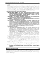
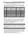
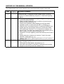
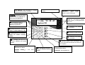
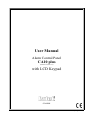
User Manual Alarm Control Panel CA10 plus (software version 4.7) with LCD Keypad GDAŃSK ca10plcu_e 07/03 WARNING In order to avoid any operational problems with the control panel, it is recommended that you become familiar with this manual before you start using the equipment. Telephone terminals of the panel should be connected to PSTN lines only. Connecting to ISDN lines may lead to damage of the equipment. In case of upgrading the PSTN line to ISDN, system owner should contact the installer. Making any construction changes or unauthorized repairs is prohibited. This applies, in particular, to modification of assemblies and components. Maintenance or repair operations should be performed by authorized personnel (i.e. the installer or factory service). CAUTION! The alarm system is fitted with a battery. After expiry of its service, the battery must not be thrown away, but disposed of as required by the existing regulations. (European Union Directives 91/157/EEC and 93/86/EEC). The SATEL Company recommends that operation of the whole alarm system be regularly tested. However, a reliable alarm system does not prevent burglary, assault or fire from happening, it only diminishes the risk that such a situation will cause no alarm or notification. History of the updates to this manual is attached at the end hereof. Control panel CA 10 plus with an LCD keypad Alarm control panel CA10 plus is a modern, microprocessor-based device designed for signaling burglaries and assaults. The CA-10 plus panel controls the operation of an alarm system, responds to information coming from the alarm system detectors about an intrusion on a protected facility and informs about the event. The panel is designed to be operated with LCD display keypads and LED keypads. Basic functions of CA-10 plus: • signaling burglary, panic and fire alarms, • informing of alarms with telephone voice messages or messages to a paging system, • answering phone calls and informing the user of system status (whether an alarm occurred since its arming), • monitoring - communication with telephone monitoring stations (real-time transmission of detailed information about specified events in a protected facility), • real-time printout of reports on all events in the system on an external printer. Features of CA-10 plus: • panel operation controlled with LCD text display keypads (2x16 characters), • clear text messages describing system status and important events, • installer-defined zone descriptions simplifying identifying the alarm origin, • simultaneous detailed status presentation of up to 16 zones controlled by the panel, • visible clock and system date display helpful in supervising and ensuring error-free operation, • reviewing the alarm and trouble logs (or detailed memory log of all system events) with text description, zone name, partition name or user name and exact time of the event, • access to numerous USER FUNCTIONS by means of function list item selection. Armed modes To adapt the alarm system to various needs the control panel CA-10 plus offers several armed modes: Audible armed mode The mode in which detectors connected to the panel control the protected facility and violation of the protected zones is signaled by the panel with all available means (sirens, monitoring stations message transmission, telephone messages). Silent armed mode Armed mode in which alarms are signaled only in the panel keypads. The installer can decide which of the detectors are automatically by-passed in this mode; he can also choose signaling device to be used in that mode. Partial armed mode The installer can determine the detectors in the system which will be excluded from the surveillance on arming the system with the special access code (authority level 7). It enables the user, by entering an appropriate code, to arm the system fully or in a chosen part only. 2 Control panel CA10 plus with LCD keypad - User's Guide Stay armed mode In this mode the panel enables automatic bypassing of chosen detectors if immediately after arming the system the user did not leave the facility and did not activate the entrance/exit detector. Operating instructions Operating of the alarm system consists basically in arming and disarming the system (setting surveillance mode) and offering an appropriate reaction to the information the control panel signals on the keypad. The keypad displays the information about the status of the alarm system by means of a two-line, backlit LCD display (2x16 characters) and six additional LED controls. LED functions: • ALARM - diode on - signals alarm, • TROUBLE - diode blinks - the control panel detects technical problems or telephone messaging system breakdown, • PARTITION 1 ... PARTITION 4 - diodes on - the status of partitions is shown: the LED blinking (with the ALARM LED control off) signals the start of the countdown for exit; the LED on signals partition armed mode. User access codes For everyday operation of the system assigning user access code is essential. The control panel comes with one factory-set code (master user code) for each partition: 1234 for partition 1, 2345 for partition 2, 3456 for partition 3, 4567 for partition 4. Programming of additional 12 user access codes is possible in each partition (but no more than 32 in the entire system). The code can be 4 to 6 digits long. By creating new user access code, the master user assigns specific, so called, authority level - determines which of the panel functions are available for a particular user, and which are excluded. Normally entering access code in one keypad will affect only in one partition. It is possible to switch on installer accessible option "global access codes". Switching on this option causes, that users access codes are accepted in all 4 partitions: each user can access do any of existing partitions. In this case there will be no information about user number in panel’s event log. Arming [Access code][#] Arming is only possible when the partition is not signaling alarm and is not already armed: ALARM and PARTITION diodes are off. In order to arm the system access code should be entered and confirmed by pressing [# ] key. If, while typing the code, user makes a mistake [*] key should be pressed and the code re-entered. When the code is correctly entered the display shows both a message confirming entering armed mode and the name of the user who activated it. Then an exit Control panel CA10 plus with LCD keypad - User's Guide 3 countdown message is displayed (if the option was allowed by the installer). The partitions in which the countdown procedure is on are visually represented by blinking PARTITION diodes with appropriate partition numbers. Accepting the command to arm the system can also be confirmed with an appropriate sound code: three short beeps (if the option of key sound confirmation was turned on by the installer). The panel may fail to arm the system if: • in the panel there are specifically designed zones which cannot be violated while the system is being armed and one of them is being violated at the time - the panel signals the situation with three long beeps. In such a case a delay is recommended until all the exits are ready and arming the system again. Pressing the Õ button displays the exits being violated. If one of the exits remains violated (the cause being, for example, the detector trouble) the armed mode can be switched on after the exit has been blocked (function 4), • access code entered is incorrect - the control panel signalizes the event with two long beeps • in the partition there are no armed type zones - the control panel signalizes the event with two long beeps (access code is correct and allows, for example, to call user functions). • battery trouble - three long beeps (proper option is selected to prevent the system from being armed in case of battery trouble). Quick Arming [0][#] On pressing the sequence [0][#] user can, without typing access code, arm the system. The Quick Arming function can be blocked by the installer. Arming is not influenced by any detectors being violated at the time. The installer can assign a special key to arm the system quickly. Disarming and clearing the alarm [Access code][#] When the control panel is armed (PARTITION diode is on) or signalizes the alarm (ALARM diode is blinking) it can accept only one order - disarming the system or clearing the alarm. Typing the access code confirmed by pressing [#]keys disarms the system or turns off the alarm. If, while typing the access code, user makes a mistake, she/he should press [*] button and re-enter the code. The control panel will not be disarmed or allow the alarm clearing if: • the access code is incorrect, • or the access code authority level does not allow disarming (for example authority level 3 or 9 - see "User Functions Menu" - "New User") It is possible to cancel the alarm without disarming the system with authority level 0 access code. Disarming the system is confirmed with an appropriate message on the LCD display and the name of the user who armed the system. If the alarm has been cleared the keypad will display the message "Review ÇÈÅÆ" - the arrow buttons allow reviewing partition status to find out the source of alarm. In the alarm system divided into zones, it is only possible to cancel the alarm in the zone, whose keypad is signaling alarm with its ALARM LED. By pressing the × key you can check in which zones the alarm was triggered. 4 Control panel CA10 plus with LCD keypad - User's Guide Timer Controlled Arming and Disarming Arming and disarming of the system can be controlled with a control panel timer. The installer can program the exact hour and minute of arming/disarming of the system. Arming and disarming will occur every day at a specified time. The control panel can also be armed with a timer and disarmed manually by a user. Alarm System Status Telephone Messages The owner of the facility with CA-10 plus control panel installed can check if the alarm is on by means of a standard telephone connection. In order to do so he has to phone the facility - the control panel will answer the phone and will brief the caller on the system status. The control panel will answer telephone calls only when the whole protected facility is armed. On receiving the call the control panel sends: • one beep a second - if, since the last arming time, there no alarm occured; • speech synthesizer message - if the alarm occurred within the last hour; • sequence of five short beeps - if the alarm occurred more than an hour ago. The installer decides if the function is on and how the control panel answers the phone calls (number of rings, double calling etc.). Control Panel Interfacing with MST-1 Telephone Control Module The control can be effected from a telephone the control panel calls up during voice messaging (immediately after the message from speech synthesizer is reproduced), or after a connection is established with the panel from any telephone set. Having answered the call, the module connected to the CA-10 plus reports its readiness with three beeps (high-, low- and high-pitched). It is possible to perform operations of two types: 1. Checking the status of zones or partitions. 2. Performing a user function. The below table presents the functions performed by the MST-1 module: CODE [0][#] [1][#] [2][#] [3][#] [4][#] [9][#] [CODE][#] [CODE][¼][4] [CODE][¼][5] [CODE][¼][7] [CODE][¼][8] DESCRIPTION End of connection with the control panel Checking the status of partition 1 Checking the status of partition 2 Checking the status of partition 3 Checking the status of partition 4 Checking zones status Arming/disarming, alarm clearing Zones bypass Silent arming Controlling of the output of ”MONO switch” type Controlling of the output of ”BI switch” type The control is performed using DTMF signals of the telephone keyboard. To call the selected function press sequentially telephone keys in accordance with the calling method as shown in the table. Control panel CA10 plus with LCD keypad - User's Guide 5 Partition status signalling: • three short beeps – partition disarmed; • four short and one long beeps - partition armed. Alarm in a partition or memory of an alarm are signalled with a series of short beeps (changing from high to low) that last approx. 2,5 seconds directly after signals informing on partition status. The function ”Checking zone status” can readout the information, which of keypad’s LEDs shine with a steady light and which of them are blinking. During co-operation with CA-10 plus control panel the module informs in accordance with the settings of service functions FS 12 do FS 15. The indication of a zone of an armed partition means memory of an alarm triggered by this zone, while the indication of a zone of a disarmed partition means violation of the zone. In the CA-10 plus control panel the installer himself defines the numbers of zones to be indicated by LEDs of the keypad assigned to the partition (such keypad needs to be connected to the control panel). It is possible to check the status of LEDs numbered from 1 to 12. The method of checking the zone status: • After the first calling of the function [9][#], the module generates short beeps, the number of which is equal to the lowest number of a shining LED. If none of LEDs shines, the module generates two long beeps. • The subsequent calling of the function [9][#] indicates the next LED, which is shining. The review needs to be continued till hearing two long signals informing that there are no more LEDs shining. The repeated calling the function (after two long signals) will restart the review of zone status. Õ×ØÖ Key Functions Activated by installer functions assigned to Õ×ØÖ keys help in everyday control of the system operation. Find the partition where alarm was activated × key In multi-partition systems the find function enables determining the partition where alarm was activated. On calling, the function shows by means of PARTITION diode(s) the partition(s) where alarm was activated, and on the LCD display the names of partitions (every time the × key is pressed next partition name is shown). Find the violated zones Õ key The function displays the names of violated zones. The zones are shown on pressing the Õ key (the function shows the partition zones as selected in "Zone Setup" by the installer. Find the zones that caused the alarm Ö key The function displays the zone names for which the alarm has not yet been cleared (individual alarm memory for zones). Every time the Ö key is pressed next zone name is shown. 6 Control panel CA10 plus with LCD keypad - User's Guide Find the partition where the keypad is attached Ø key The function displays the name of the basic partition operated with a keypad (the partition to which the keypad is physically attached). User "HOLD DOWN" Functions The functions are available to every user (without entering any access code). They are activated by holding the function key down for a short time. Switching to n partition (GO TO n) cdef In alarm systems divided into several partitions (subsystems) single keypad control over the whole system is possible. The keys 1, 2, 3, 4 kept down for a short time switch the partition the keypad is currently controlling. The keypad remains in the chosen partition for some time and then returns to its basic partition. It is possible to switch between the partitions and return to the basic partition by holding the appropriate number key down. For example: the keypad is attached to partition 1 (it is its basic partition), after holding down the key 2 for a short time it is switched to partition 2, after repeating the procedure with key 3 it is switched to partition 3, and after holding down key 1 the basic partition returns. Attention: The GOTO function described above is active only when the installer sets the parameter Function GOTO - Calling mode - according to LCD. Alarm Memory Review g Holding down key 5 activates the Alarm Memory Review function. The message "Alarm Memory Review ÇÈÅÆ" is displayed. Pressing any of the arrow keys causes the date, time, and last alarm origin name to appear. Pressing × or Ø keys enables scrolling the event log. Pressing Õ and Ö keys causes the zone description to appear. [*] key cancels Alarm Memory Review function. The control panel distinguishes between three types of alarms: zone alarms - break-in, assault, fire etc. alarms set-up by the installer, anti-tampering alarm - signaling attempts to dismantle or damage any part of the alarm system, keypad activated alarm - fire, auxiliary or panic type alarms. Trouble Memory Review h On holding down key 6 the "Trouble Memory Review ÇÈÅÆ" message is displayed. Pressing any of the arrow keys causes the date, time, and last trouble type detected name to appear. On pressing × key the list of previously detected troubles is displayed, on pressing Ø key the list of subsequent troubles. [*] key cancels the function. Current Trouble Check-out i When the control panel signals a trouble detection (TROUBLE diode is blinking), holding down key 7 activates the Current Trouble Check-out function. On the keypad display a trouble message appears. If there are more than one trouble pressing of Õ× or ØÖ allows scrolling through all the troubles detected. Control panel CA10 plus with LCD keypad - User's Guide 7 NOTE: If the installer has activated the "Indicate trouble until cancelled" option, the trouble indicator will be on until cancelled, even if the trouble cause has been removed. The trouble will be cleared after completing the trouble memory review and quitting the function by pressing the [#] key. Quitting the function by means of another key will not cancel blinking of the TROUBLE diode. The control panel detects the following problems: "No 230V power supply" - the control panel is equipped with back-up power supply that enables it to function for a specified period of time. If, however, the "non 230V power supply" message appears in spite of the fully operational wiring, service should be informed. "Clock loss" - the message appears on disconnecting and reconnecting the control panel; the clock can be set with user function 6. „No battery” – the battery is not connected or almost discharged or the fuse on the control panel board is out of order. "Low battery" - the message appears when the battery voltage is too low (lower than 12V under normal operational load). The state may hold for several hours after current supply disconnection (or after connecting a low battery). The battery charging time is dependent on its capacitance (the battery is charged with 350mA or 700 mA direct current, the battery testing time necessary for determining its state is about 12 minutes) Telephone line troubles: • "No voltage on the telephone line" - the message appears when the telephone line to which the control panel is connected is cut off. It may also appear when the telephone connected to the same line is off hook for longer than the time specified by the installer (service function FS117) • "No dialtone" or "Wrong dialtone" - the cause of the message is telephone connection trouble (no signal or busy signal on lifting the receiver). The message does not disappear till the next, successful telephone connection. It can be cleared by calling the alarm check function and pressing [#] key. "Output trouble" - no detectable load (for example the siren wiring is cut) or overloading (short circuit) - in most cases service should be called. "No RS printer" - stands for "not-ready" status of the printer attached to RS232 port of the control panel, (as a result of, for example, paper load trouble or no power supply). The RS-232 port is monitored if the installer sets up real time event printout. "RAM error" - the message appears on erratic microchip operation of the system (it may be caused by strong electromagnetic interference produced by lightning) - in most cases service should be called. "Keypad power supply trouble" - signals an installation error; servicing is necessary (the message can be displayed only while reviewing alarm memory). Switching the Chime on/off j The function enables switching the chime on/off (acoustic signaling of the violation of specified detectors) by means of the keypad. The switching off of the function with the keypad is confirmed with three short beeps, switching on - with one longer and four short beeps. 8 Control panel CA10 plus with LCD keypad - User's Guide The installer decides which zone and which keypads can use chime to signal their status. Fire Alarm (*) The function enables switching on/off of fire alarm by means of the keypad. b Auxiliary The purpose of the alarm depends on the current needs. It may, for instance, be an emergency call for doctor's help. The function may transmit an appropriate message to monitoring station and activate voice messaging. Panic alarm (#) The function enables activating the panic alarm by means of the keypad. CHANGING DISPLAY MODE OF SYSTEM STATE Ø This function makes it possible to change the LCD display operating mode from displaying text messages about the system state into displaying the state of armed zones (or the other way round). The keypad will automatically return to the installer set operating mode after approx. 40 sec. User function menu If the control panel is not armed and is not signaling any alarm, after entering the access code and pressing [*] key the panel switches to user function selection mode. The beginning of the list of user functions appears on the keypad. The set of user functions currently available depends on the authority level of the access code with which the user functions menu was activated. the arrow points to the function that will be activated by pressing # or Ö key Æ Change own code Add user list of functions: 1. Change own code 2. Add user 3. Erase user 4. Bypass zones 5. Arming silent 6. Set time 7. Mono output activate 8. Bi output switch 9. Supply reset 0. Tel. DWNL start Events review The Ø × keys enable scrolling through the user functions. [#] and Ö keys activate the given function. It is possible to activate a function directly - when User Functions Menu appears on the display - by means of pressing an appropriate numeric key, similarly to calling a function by means of LED keypad. Choosing User Functions with the Menu is very simple as the display shows clear function descriptions. NOTES: The functions 2 and 3 are only available to the partition master code user. Control panel CA10 plus with LCD keypad - User's Guide 9 The functions 7 and 8 are always available, irrespective of whether the control panel is armed, or not. Access Code Change (function 1) The function enables changing the access code of the user who called it. On calling the function a new code should be entered and confirmed by pressing [#] key. The keypad will confirm the access code change and will display the new user's name. The function is available to the master user and users with authority level 1, 2 or 7. New User (function 2) The function is available only to the master user. The user can add new users to a specific partition, assigning an access code to them and determining their authority level. The master user, thus, determines the extent of the remaining users' control over the system. The function enables new access code programming, determining new code's authority level and entering new user's name. An access code can have the following authority levels: 1 - all functions available except for creating and deleting users, 2 - arming and disarming functions available as well as changing access code, 3 - arming function available as well as disarming, but disarming only on condition that the system was automatically armed 4 - access code - trap: arming and disarming functions available but after disarming the system the "DURESS" message is sent to the monitoring station 5 - activates the output of mono type (the use of the switch is determined by the installer) 6 - switches the output to bi type (the use of the switch is determined by the installer) 7 - partial arming of the system: the code arms the system with simultaneous bypassing of a group of zones (determined by the installer in service functions), except for that the code gives the same authority as level 2, 8 - arming and disarming available without the possibility of changing access code, 9 - only arming available, 0 - only clearing the alarm available NOTES: The access codes of type 5 and 6 may be used in the following way: 1. In the user function basic mode ([CODE][*]7 or [CODE][*]8) which allows multiple control of single outputs (see description of user functions). 2. In the mode realized in the previous versions of alarm control panel (i.e.. [CODE][#]), which simultaneously controls all the particular types of outputs belonging to the partition to which the given access code is assigned. Using the access code with authority level 5 or calling the function 7 is recorded in event log as the „Entry/Exit (guard round)”. 10 Control panel CA10 plus with LCD keypad - User's Guide To make the control possible, there must be compatibility between the code type, output type and partition assignment. New user's access code can be edited with additional arrow keys. After confirmation of the new access code and its authority level the keypad displays the current name of the user, for example "P.1 user 1". It can be changed by entering new name (max. 16 characters). Key Numeric mode Text mode × deletes the character before the the previous character in the cursor alphabet Ø switches between insert/typeover the next character in the modes alphabet 1 1 . , 2 2 A a 3 3 B d 4 4 G g 5 5 J j 6 6 M m 7 7 P p 8 8 T t 9 9 W w 0 0 space While programming text messages the keys ÕÖ change the cursor position, [*] key switches the operating function mode (numeric or text), and [#] key confirms the entered text. The remaining keys has functions dependent on the operating mode. Text mode is signaled with a * sign in the upper right corner of the display. Numeric keys in text mode insert letters at the cursor position according to the preceding table. Small characters are entered by pressing a numeric key twice. × Ø keys enable the previous/next character selection. In numeric mode × key deletes the character before the cursor, and Ø key switches between insert/typeover modes. Delete User (function 3) The function enables deleting the user selected with the cursor (blinking field). On pressing and holding down the × or Ø key the name of the user indicated with the cursor appears. The cursor can be positioned with ÕÖ. Function is available only to the master user. Zone Bypassing (function 4) The function enables zone bypassing in order to partially switch off the alarm system in the protected facility or skip the broken down detectors. Ø key changes the status of the zone (operational/bypassed) indicated by the cursor. Pressing × key displays the zone name. The cursor can be positioned with ÕÖ keys. It is possible to choose a zone by giving its number with the numeric keys of the panel (for example: [*][3] will enable bypassing of zone 13). The function is available only to the master user with authority level 1. Control panel CA10 plus with LCD keypad - User's Guide Silent Armed Mode 11 (function 5) In silent armed mode the alarms are signaled only in keypads and by sending an appropriate message to monitoring station. The installer decides if silent armed mode is valid in all the protected facility or if in a selected area it will be disarmed. The function is not available for user with authority level 5, 6, 0. Setting Time (function 6) The programmable parameters (time, data, year) can be edited with additional keys: Õ and Ö keys position the cursor, × key deletes the character before the cursor, Ø key switches data entry mode (insert/typeover). The function is available only for the master user and a user with authority level 1. Mono Switch (function 7) The purpose of the function will be determined by the installer. It can activate e.g. electric locks, bells, signal lamps, or any other devices. After calling the function, the control panel generates two short beeps and waits for the output number key (1-6) to be pressed. Provision is made for multiple control of the same output or control of different outputs of the MONO switch type after single calling of the function. Correct performance of the control is confirmed by four short and one long beeps, and refusal of the control - by two long beeps. The control panel may refuse control, if the output is not of the "MONO switch" type or if it belongs to another partition. Pressing the key [#] or [*] will end the function. The control panel will automatically end the function if none of the outputs is of the „MONO switch” type, or if no key on the keypad is depressed for 40 seconds. The function is accessible to the master user, as well as to the users with authority levels 1 and 5. Bi Switch (function 8) The purpose of the function will be determined by the installer. It can be used e.g. for switching on external lighting or any electrical equipment. After calling the function, the control panel generates two short beeps and waits for the output number key (1-6) to be pressed. Provision is made for multiple control of the same output or control of different outputs of the BI switch type after single calling of the function. Activation of the output is confirmed by four short and one long beeps, and its deactivation - with three short beeps. Refusal of control is signaled with two long beeps. The control panel may refuse control, if the output is not of the "BI switch" type or if it belongs to another partition. Pressing the keys [#] or [*] will end the function. The control panel will automatically terminate the function if none of the outputs is of the „BI switch” type, or if no key on the keypad is depressed for 40 seconds. The function is accessible to the master user, as well as to the users with authority levels 1 and 6. 12 Control panel CA10 plus with LCD keypad - User's Guide Power Supply Reset (function 9) The function is used with special detectors equipped with individual on/off memory which is cleared by shutting down power supply (for example smoke detectors, broken glass detectors) The function temporarily disconnects power on the power outputs with RESET function. The function is available for the master user and a user with authority level 1. Start Download (function 0) The function can be activated by the master user and a user with authority level 1. It starts the control panel - servicing PC remote telephone connection. The function enables the panel - PC telephone connection when an attempt at establishing connection from the outside computer is blocked. When the panel is in DOWNLOAD mode the telephone line is busy only while data is being transmitted. During programming sessions the PC can send a request to stop the current connection and wait for the next one. Such an attempt at re-establishing connection will be accepted by the panel regardless of the outside connections being blocked. Closing the programming session will be successful after the PC sends the "CLOSE" message or after four hours since the last connection elapse. Reviewing Events Memory Log (additional function) On activating the function users can review the memory log in which all the events are recorded in detail. ×Ø keys enable scrolling the list of events, ÕÖ keys enable additional data display: zone descriptions, partition and user names. The function is not available for the master user and users with authority level 1. Technical Reliability of the Alarm System The alarm system is built of the devices whose reliability is vital in effectiveness of offered protection. The elements of the alarm system are subject to various outside influences, for example weather conditions (outside signaling devices), lightning (overhead telephone lines, power lines, outside signaling devices), mechanical damage (keypads, detectors). Only permanent control of the alarm system operation ensures keeping high level of burglary and fire protection. The control panel is equipped with a number of safeguards and auto diagnostic functions testing the reliability of the system. The control panel signals trouble detection by switching the TROUBLE control on the keypad on. The signal should be immediately taken care of - if necessary, the installer should be consulted. It is necessary to periodically test the reliability of the alarm system - check every single detector's ability to signal zone violation by opening the protected windows, doors etc. It is also necessary to check signaling devices and telephone voice messaging system. The installer gives specific instructions on how the system should be controlled. Periodic commissioning of the installer's maintenance service is strongly recommended. HISTORY OF THE MANUAL UPDATES The updates below refer to the manual for the control panel with program version 4.1. Date Program version 08-2002 4.2 01-2003 4.3 07-2003 4.7 Description of updates A new section added: operation via a telephone of the control panel working with MST-1 telephone control module (see p. 4) (NOTE: Control is not made available by the panel, if it calls itself reporting an alarm). • Disarming only effected by entering [CODE][#] from keypad (p. 3) – previously also [CODE][*]. • "Battery trouble" added as one of conditions of preventing the system from being armed (p. 3). • Control panel operation made available on receiving alarm message in case of a joint work with MST-1 module (p. 5). • Change of the control panel reaction to entering [CODE][*] from keypad. Now the panel always enters the user function mode, thus enabling the functions 7 or 8, irrespective of whether it is armed or not. The other user functions are only available with no alarm condition and the system disarmed (p. 9). • Introduction of notes regarding codes with authority level 5 and 6 (p. 9). • Audible distinction introduced in functions 7 and 8 for output activation / deactivation (p. 11). • Change of description regarding performance of user functions 7 and 8 (p. 11). • A note on functioning of the trouble indicator has been added (key 7 function - p. 7). • A new type of trouble added: „No battery” (p. 7). • New option that applies to possibility of activation the functions assigned to arrow keys has been added (s. 5). ALARM - alarm in the current partition LCD DISPLAY: time and date or partition name and system status message TROUBLE - signals trouble detection in the system - to check press i key for 3 seconds cdef - pressing any of the keys for 3 seconds switches to one of the four partitions CA-10 LCD 1 Jan, 12 : 35 : 47 g - pressing the key for 3 System OK seconds activates Alarm Memory Log Review 1 2 3 4 5 6 7 8 ALARM TROUBLE PARTITION 1 9 10 11 12 13 14 15 16 PARTITION 2 PARTITION 3 h pressing the key for 3 seconds activates Trouble Memory Log i - pressing the key for 3 seconds displays the trouble currently detected 1 2 3 4 5 6 7 8 9 * 0 # PARTITION 1, 2, 3, 4 control on - the zone is armed; control blinking - counting down exit delay time PARTITION 4 × - identifying the partition signaling alarm Õ - identifying violated zones Ö - identifying zones where alarm occurred j - pressing the key for 3 seconds switches the chime on/off Ø - displaying partition name, pressing the key for 3 seconds switches between text and zone state displaing [*] - pressing the key for 3 seconds activates Fire Alarm ACCESS functions CODE+[*] - user menu b - pressing the key for 3 seconds activates Auxiliary Alarm [#]-pressing the key for 3 seconds activates Panic Alarm CODE+[#] – arming/disarming