1
HOTMIX!
HOT MIX ASPHALT DESIGN EXPERT SYSTEM
FINAL REPORT IR-90-02
September 1990
David J. Elton
Lisa Waldroup Dukes
A report to the Alabama Highway Research Center
Dr. Frazier Parker, Director
HOTMIX! - Hot Mix Asphalt Design Expert System
I. Introduction
HOTMIX! is a expert system computer program created to assist in the design of asphalt
aggregate mixes. This program assists the hot mix asphalt design engineer in creating the design,
making the laboratory mixture, and evaluating the results. The strength of the program is it's ability
to provide specific advice on improving the mix to bring it into compliance.
HOTMIX! provides advice with two tools - hypertext and the inference engine. Hypertext
allows the user obtain background information pertaining to certain "hot" words (text) or phrases
on the screen. When the user places the cursor on a hypertext word (denoted by being highlighted
on the screen), a pop-up window appears that gives more information on the word/phrase in
question. Hypertext appears throughout HOTMIXL
The inference engine is what makes HOTMIX! "smart". This part analyses the results of
the laboratory mix design and tests, and reasons; after a fashion, reaching conclusions that tell the
user if the mix is within the specifications. If it is out of specification, the engine triggers advice
on how to bring it into compliance. The ability to only trigger the advice needed for the problems
the mix at hand has makes this part of the program unique.
HOTMIX! expertise was generated from experts in industry, government and academe,
listed in the Acknowledgments. Using these three different viewpoints removed the potential for
bias from anyone organization's purposes and experience. The functioning and purpose of the
program was defined by these experts as the program was being developed - making it useful to the
profession.
HOTMIX! was developed using 1st Class HT expert system development tool. HOTMIX!
offers expert advice and background information on each step in the mix design process. HOTMIX!
has the following features:
*
An Aggregate Blending Program which allows blending and automatic plotting of
several aggregate stock piles and mineral fillers into a blend that fits one of three
FHWA specifications.
*
A Marshall Mix lab data reduction program, including onscreen plotting.
*
The Asphalt Institute Marshall Mix design procedure. HOTMIX! does this by
examining the plotted data, retrieving the appropriate peak values and making the
optimum asphalt content calculation.
Plots of flow, stability, voids in mineral aggregate (VMA), voids filled with asphalt (VFA),
unit weight, and air voids (AV) versus the percent of asphalt cement contained in the mix are
created by using the Marshall mix procedure and the Marshal mix design. The program uses four
percent air voids to calculate the optimum asphalt cement content, stability, VMA, VFA, and flow.
1
The program uses these values to determine if a supported parameter is inadequate. The
parameters that are supported are flow, stability and VMA. If a parameter falls outside the
accepted values, the program gives advice to help solve the problem. The advice given was
gathered from interviews with recognized experts in the field of asphalt design.
Specific instructions on running HOTMIX! are included in the companion user's manual.
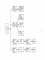
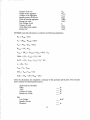
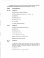
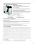
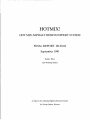
II. Program Format
HOTMIX! is composed of the following sections:
Asphalt Preparation
Blend Preparation
Marshall Mix Procedure
Marshall Mix Design
The structure of each of these sections is discussed below.
A. Asphalt Preparation (Information Only)
This section contains general information about the asphalt cement needed to make the
pills used in the Marshall Mix Procedure. It is included for the benefit of those new to the area
of asphalt design. The purpose is to provide a basic understanding of the asphalt specification.
The following information is included:
One gallon of asphalt cement is needed to make the asphalt concrete pills. Be sure a
sufficient quantity is on hand to make all the pills from one batch of asphalt cement. Using
different asphalt cements in the same batch may cause mixed results. Make sure the correct
viscosity-graded asphalt cement is being used [AC-20 is typical].
The asphalt cement should come from the same supplier that the contractor is planning
to use on the job. Slight differences in asphalt cement may cause differences between the lab
mix and performance of the mat in the field. If the asphalt cement the contractor will use is
not available, use an asphalt cement of the same grade.
There is much that is not yet understood about asphalt cement. Consequently, sometimes
two asphalt cements that meet the ASTM specification will perform differently. Therefore, it
is important to use the same asphalt cement in the lab as will be used in the field.
Penetration-graded asphalt cements are sometimes used. The specifications for these
are given in ASTM D946. (Appendix A)
Viscosity-graded asphalt cements are also commonly used. Their specifications are given
in ASTM D3381. (Appendix B)
2
Asphalt
Cement
Preparation
......
....
......
Information on
Asphalt Cement
Preparation
General
Information
on Aggregates
>....
c
UJ
Blend
Preparation
::J
~
c
'(ij
~
......
....
......-
Aggregate
Plots
~
C
Q)
,
......
M
Blend
Stockpiles
Marshall
Mix
Procedure
Marshall
Mix
Design
......
....
......
Data
Entry
........ .......
Specific
Gravity
Calculations
.......
Results
......-
Plots
.....
Conclusion
Screen
......
Advice
B. Blend Preparation
This section contains general information on aggregates. This part of the program
allows the user to blend stockpiles graphically or numerically on the screen. The user can enter
up to five different aggregates, specifying the grain size distribution and texture (whether the
aggregate is crushed or natural) of each aggregate. The grain size distribution is specified by
passing a sample through a set of sieves and recording the percent of the sample that is retained
on each sieve. The user then enters those percentages on an input screen. These gradations
are then plotted onscreen, superimposed on the user-selected acceptable gradation range.
By choosing percentages of each aggregate gradation, the user is able to blend the
aggregates together graphically. A composite gradation, consisting of the selected percentages
of each aggregate, appears on the screen. The user can try different combinations of the
gradation until the gradation curve falls within the specification range. While selecting these
percentages, the user can, at any time, view the combined gradation plotted on any of three
variations of the Fuller curve.
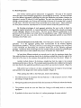
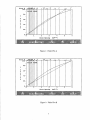
General Information on the Fuller Plot. The Fuller plot is another way to represent a
gradation. It is the aggregate grading chart recommended by the Federal Highway
Administration (FHWA). The chart, based on a scale raising sieve opening to the 0.45 power,
is very convenient for determining the maximum density line and for adjusting aggregate
gradings. Gradations which closely approach the straight maximum density line generally give
low VMA values and are often shifted away from it to increase the VMA values.
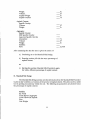
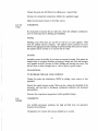
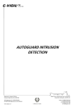
At least three different methods are currently used to plot the maximum density line.
One method obtains the maximum density line by drawing a straight line from the origin at the
lower left of the chart to the maximum (top) particle size at the top of the chart. (Figure 1).
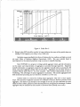
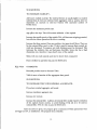
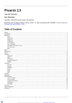
Another method obtains it by drawing a straight line from the origin to the nominal
maximum particle size at the top. The nominal maximum particle size is defined as the largest
sieve size listed in the applicable specification upon which any material is retained. (Figure 2).
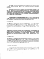
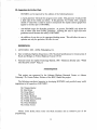
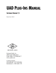
Still another way to obtain it is to draw a straight line from the origin to the percentage
point plotted for the largest sieve with material retained. (Figure 3).
When plotting the GSD on the Fuller plot, observe the following:
1.
The GSD should not be coincident with the Fuller line - it will surely have too Iowa VMA
percentage, but high density.
2.
Moving the gradation away from the Fuller line increases the VMA and reduces the density.
3.
The gradation should not cross the Fuller line. Doing so will usually lead to a mix that
segregates-.
4. If gradation is above curve, but close to it, reduce percentage of coarse material.
4
:l.11I11151113tl1:1.b
e.
2BB B1Iio4B -?1lI
:l.B
Sieve B
::l..ea
4
.25"
.5 11
.S7S"
:I."
.75"
F~~L~IRI bJRV~
,
8121
-
6181
-
4181
-
2181
-
,
X
P
a
s
s
i
e
~
v::.
V'"
V
~
/"
1--'
2"
~
//
iJ~
I
n
g
:1..5"
/"
J~
~/,
'1.
~
/"
pfr/
!,
!
?
'$
Sieve Opening
4
5;
(
(",,,,B. 45)
Figure 1: Fuller Plot A
2"
p
a
s
s
i
n
g
4
Sieve Opening
(",,,,B. 45)
Figure 2: Fuller Plot B
5
2"
~12l
p
a
_.
612l
s
s
i
n
g
413
212l
4
Sieve Opening
(",,,,11I.4!J;)
Figure 3: Fuller Plot C
5.
Humps in the GSD should be avoided. A hump indicates that some of the particle sizes are
missing. If this happens, you will get a dry, brittle mix.
Gradation ranges specified by the State of Alabama for low, medium, and high use roads
are used. (State of Alabama Highway Department, 1985). The user selected blend is
superimposed on the selected gradation range on screen to simplify blending.
Since HOTMIX! is a program to design asphalt aggregate mixes, general information
on the nature and characteristics of aggregates is provided through hypertext. Hypertext
includes information on aggregate categories: fine aggregate (usually taken as passing the #8
sieve), and coarse aggregate (larger than the #8 sieve). Aggregates can be either natural or
crushed. Natural sands tend to be more rounded. This rounded characteristic is due to
weathering. The advantage of natural aggregate is economics. The natural aggregates have
little mechanical processing and are therefore available at a lower cost.
Crushed sands are created by crushing larger aggregates. They have a more angular
shape. This increased roughness increases the coefficient of friction between particles in the
aggregate. This leads to an increase in the strength of the mix, and also decreases the mix's
ability to flush or bleed. All three of these characteristics are recognized as advantages. Crushed
aggregates may be classified by their number of fractured faces (usually one or two).
6
The FHWA has recommended limits of the amount of natural sand that can be used in
a mix, for higher volume roads. Mixes with too much natural sand tend to shove when
compacted.
MINERAL FILLER. "Mineral filler" is any inorganic material that passes the no. 200
sieve. This material may be Portland cement, lime, baghouse fines, ground agricultural lime (if
it does not contain particle sizes larger than no. 200), or material from wet washing aggregates
(sump residue). Mineral filler should be entered as a separate stockpile. If ground agricultural
lime has particle sizes larger than no. 200 sieve, the grain size distribution must be input, in
order to blend it with the other stockpiles.
Gradation Ranges - low, medium, and high use roads. The State of Alabama specifies
a range of gradations for each of three different levels of road use; low, medium, and high. The
road classifications are based on how much traffic is anticipated for that road.
A) Low use road
The A gradation is usually used for base course of asphalt concrete. It is an open gradation
with a 2.0 inch maximum aggregate size, used as the bottom asphalt concrete layer in the
pavement structure. The gradation shown in the FHWA gradation taken from the "Standard
Specifications for Construction of Roads and Bridges on Federal Highway Projects", FP-85,
1985.
B)
Medium use road
The B gradation is usually used for binder course of asphalt concrete, placed between the base
course (A) and the surface course (C). It is a fairly open gradation with a 1.5 inch maximum
aggregate size. The gradation shown in the FHWA gradation taken from the "Standard
Specifications for Construction of Roads and Bridges on Federal Highway Projects", FP-85,
1985.
C)
High use road
The C gradation is usually used for surface course of asphalt concrete. It is a closed gradation
with a 1.0 inch maximum aggregate size. This layer is used as the top asphalt concrete layer
in the asphalt concrete pavement structure. The gradation shown in the FHWA gradation taken
from the "Standard Specifications for Construction of Roads and Bridges on Federal Highway
Projects", FP-85, (State of Alabama Highway Department, 1985).
C. Marshall Mix Procedure
The Marshall Mix Procedure section asks the user for information about the samples
they are using. HOTMIX! uses this information to assist the user in making up the actual pills
that are needed to run the stability, flow, unit weight, and Rice specific gravity tests. The
following calculations are made:
7
The weight of aggregate needed from each stockpile to put in the mix to get the desired
gradation.
The weight of aggregate needed from each sieve to put in the mix to get the desired
gradation.
The information needed for these calculations is :
The total weight of the pill in air.
The asphalt percent based on the total weight.
This section also asks the user to give the asphalt percentage batch a name by which it
can be referenced later. These names are used to distinguish between pills with the same asphalt
cement percentage at a later point in HOTMIX!.
The theoretical maximum specific gravities and densities of asphalt paving mixtures are
intrinsic properties that are determined by the type ( natural or crushed) and gradation of the
aggregate mixture. They are used to calculate values for percent air voids in compacted
bituminous paving mixtures. They provide target values for the compaction of paving mixtures.
They are
essential when calculating the amount of bitumen absorbed by the internal porosity of the
individual aggregate particles in a bituminous paving mixture.
The Rice method is used to calculate the theoretical maximum specific gravity and
density of the mix (which includes the asphalt and the aggregate) by the ASTM D2041
(Appendix C). This program allows the user to select either the Rice Flask or Rice Bowl
method to calculate the specific gravity of the mix.
The Rice method determines the specific gravity of the sample at 25° C. The Rice bowl
method consists of:
1.
Weigh the sample in air
2.
Put the sample in the bowl
3.
De-air the sample (place under vacuum)
4.
Submerge the bowl with the sample in it
5.
Weigh the submerged apparatus.
6.
Calculate the theoretical maximum specific gravity by
using equation 1.
Gs
= A/(A-C)
8
(1)
Where:
G s - theoretical maximum specific gravity.
A - mass of the oven dry sample in air, g, and
C - mass of the water displaced by the sample at 25°C (77 OF)
The Rice flask method consist of the following:
1.
Weigh the empty flask,
2.
Weigh the flask filled with water (calibration),
3.
Empty flask,
4.
Put mix in the flask, weigh it,
5.
Fill the flask to the top with water, leave the mix
in the flask, weigh it.
6.
Calculate the theoretical maximum specific gravity
using equation 2.
Gs
=
A/(A + D - E)
(2)
Where:
G s - theoretical maximum specific gravity.
A - mass of the oven dry sample in air, g, and
D - mass of the container filled with water at
25°C (77 OF)
E - mass of container filled with sample and water at
25°C (ASTM, 1990)
Mter the specific gravity of the mix is calculated, the user is asked to enter the following:
Sample weight in air
Sample weight saturated surface dry (SSD)
Sample weight submerged
Flow
'Stability
Specific Gravity of the asphalt cement
Sample diameter
Total weight (lbs)
Total volume
9
W AIR
W SSD
W SUB
FLOW
STAB
GAC
SD
WT
VT
VAC
WAGG
Volume of the AC
Weight of the aggregate
Volume of the aggregate
Specific gravity of the mix
Voids in mineral aggregate
Percent air voids
Unit Weight of pill
Volume of voids
Voids filled with asphalt
Percent AC
V AGG
GMIX
VMA
%AV
y
Vyoid
VFA
%AC
HOTMIX! uses this information to perform the following calculations:
VFA
= VAC /
%AC = WAC
Vyoid * 100
* 100/ WAIR * 453.6
After the calculations are completed a summary of this particular pill is given. The summary
sheet contains the following information:
Alpha-numeric identifier:
VMA:
VFA:
Volume of Voids:
Percent Air Voids:
Pill:
Unit Weight:
Specific Gravity:
Diameter:
ill
10
lb
Weight:
Volume:
Asphalt Weight
Asphalt Content
ft3
lb
%
Asphalt Cement:
Specific Gravity:
Volume:
Weight:
Aggregate:
Specific Gravity:
SSD Specific Gravity:
Apparant Specific Gravity:
Absorption:
Volume:
Weight:
Stability:
Flow:
%
ft3
lb
=in/l00
After examining the data the user is given the choice of
a) Continuing on to the Marshall Mix Design,
b) Entering another pill with the same percentage of
asphalt cement,
or
c) Starting this section (Marshall Mix Procedure) again,
but with a different percentage of asphalt cement.
D. Marshall Mix Design
The Marshall Mix Design section uses the information from the Marshall Mix Procedure
to plot six key variables as a function of the percent of asphalt cement. The plots can be a useful
tool in spotting inconsistency within the mix. The following six parameters are plotted versus
the percentage of asphalt cement:
Stability
Air Voids
Voids Mineral Aggregate
Voids Filled with Asphalt
Flow
Unit Weight
11
The optimum asphalt cement is the numerical average of the peak values from the
stability and unit weight plots along with the average of the limits for percent air voids. The
Alabama Highway Department designs asphalt mixes based on four percent air voids. To
accommodate this, the program calculates the optimum asphalt cement percentage by
assuming four percent air voids. The results are summarized on the conclusion screen. A typical
conclusion screen is shown below.
HOTMIX! has calculated these numbers.
The optimum AC is:
%
The stability is:
lbs.
The opt A V is:
%
The opt flow is:
_in/100.
The opt VFA is:
%
The opt VMA is:
%
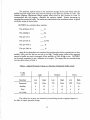
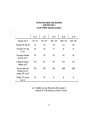
After all the calculations are completed, the program gives advice regarding how to alter
stability, VMA, and flow that are too low or too high. Certain ranges, based on the expected
amount of traffic, are used to determine if flow, stability, or VMA is high or low. HOTMIX!
can be easily customized to use a different set of ranges. The ranges that are currently being
used are given below in Table 1:
Table 1. Asphalt Parameter Values as a Function of Expected Traffic Levels'
Traffic
Level
Heavy
Medium
Light
Boundary
Low
High
Low
High
Low
High
Parameter
500
None
750
None
1500
None
Stability
8
20
8
18
8
16
Flow
8
20
8
18
8
16
Air Voids
3
5
3
5
3
5
The advice" that is given was obtained by interviewing several recognized experts in
the field of asphalt pavement design.
.
12
The advice given by the program is presented below. It is broken down into suggestions
and comments for each individual problem the program is designed to point out.
Problem
Comments /Suggestions
High Flow
COMMENTS:
If the flow is high you will get a flexible mix.
NEVER exceed maximum allowable flow. Use normal flow.
SUGGESTIONS:
TO DECREASE FLOW:
Change the grade of AC.
Use more gravel.
Use a larger maximum particle size.
Low Flow
COMMENTS:
If the flow is low you will get a dry, brittle mix.
SUGGESTIONS:
TO INCREASE FLOW:
Limestone will increase flow.
Less than 1% absorption of asphalt.
Polishing aggregate due to
nonfrictio~
values.
More crushed stone will increase flow.
High Air
Voids
COMMENTS:
It is important to decrease the air voids within a given limit even though the
stability may be satisfactory. High air void content is associated with premature
hardening of the asphalt and stripping. Stripping is a physical separation of
the asphalt and aggregate.
SUGGESTIONS:
TO DECREASE THE AIR VOID CONTENT:
13
--------- - - - - - - - - - - - - - - - - - - - -
Change the grain size distribution by adding more mineral filler.
Increase the compaction temperature (within the specified range).
Make the mix denser (closer to the Fuller curve).
Low Air
Voids
COMMENTS:
It is important to increase the air voids even when the stability is satisfactory.
Low air voids may lead to flushing and instability.
Flushing
Flushing occurs when there are too few air void (or too much asphalt). With
time, the asphalt concrete compacts. The asphalt cement squeezes out from
between the aggregate particles making the pavement slick. The cure is to reduce
the asphalt cement content or to increase the air voids.
Instability
Instability means the stability is low when the sample is loaded. This makes the
sample easier to compact, therefore producing a tender mix. The mix becomes
very unstable around 2 percent air voids. Rutting and shoving may occur. The
mix will have no shear strength due to a lack of grain to grain contact.
SUGGESTIONS:
TO INCREASE THE AIR VOID CONTENT:
Change the grain size distribution (GSD) by adding more course or fine
aggregate.
Reduce the asphalt cement content (This may also reduce the durability of the
pavement, and may lead to brittleness, accelerated oxidation and increased
permeability. )
Decrease the compaction temperature (within specified range).
Low
Stability
COMMENTS:
Low stability guarantees problems, but high sta bility does not guarantee
freedom from problems.
Changing the AC content will increase stability up °to a point.
14
SUGGESTIONS:
TO INCREASE STABILITY Add more crushed material. The internal friction is usually higher in crushed
material than in river-run material. Some aggregate, such as quartz, does not
experience an increase in inter nal friction with increased number of
broken faces.
Increase the maximum particle size.
Age pills a few days. This will increase oxidation of the asphalt.
Increase the specific gravity of the asphalt. This will decrease stripping potential,
but will also reduce pavement life due to cracking.
Increase the fines content. Fines are particles that pass the #8 Sieve. They can
be clay, mineral filler, sand, or dust. If clay is used to increase fines content, air
voids are decreased. To preserve air voids, thickness must be decreased. This
increases the oxidation rate and decreases durability. Some clay has a high
absorption rate, therefore it may absorb some of the asphalt.
Mixes with too much natural sand tend to shove when compacted.
Dust is defined as particles that pass the #200 sieve.
High VMA
COMMENTS:
Rounded particles tend to decrease VMA.
VMA is more a function of fine aggregates than gravel.
SUGGESTIONS:
TO DECREASE THE VOIDS MINERAL AGGREGATE If you have crushed aggregate, add round.
Increase maximum aggregate size.
Increase AC content.
Increase the mineral filler. Addition of mineral filler usually requires reduction
of the asphalt cement content, to avoid flushing. If fly ash is to be used as
mineral filler, 70% of it has to pass the #200 sieve.
After the advice is given, the program gives a summary of which parameters were
too high; too low, or satisfactory. The program then concludes.
15
III. Suggestions for Further Work
HOTMIX! can be improved by the addition of the following features:
a report generator will make the program more useful. This generator would provide
a hard copy of the results and advice. If the generator was written with a program
outside 1"t Class HT, it could be made to incorporate the asphalt content graphs that
appear in the final part of HOTMIX!,
user-defined ranges for allowable gradations. At present, HOTMIX! only allows the
user to select from three FHWA gradations. Allowing the user to input and store
gradations would increase the utility of HOTMIX!,
the addition of cost data on the aggregate blending screen. This will allow the user to
optimize not only the gradation, but also the cost.
REFERENCES
1.
ASTM D2041; 1990. ASTM; Philadelphia, PA.
2.
State of Alabama Highway Department, 1985, "Standard Specifications for Construction of
Roads and Bridges on Federal Highway Projects," FP-85.
3.
National Center for Asphalt Technology Bulletin, 1989. "Maximum Density Line: Which
One Should be Used?" Fall, p.6.
Acknowledgments
This project was sponsored by the Alabama Highway Research Center, at Auburn
University. Dr. Frazier Parker, Director of the HRC, funded the project.
The following contributed expertise in developing HOTMIX!, and provided many useful
suggestions in the operation of HOTMIX!:
Mr. Tommy Bender
Dr. Ray Brown
Mr. Doug Eiland
Mr. Eddie Eiland
Mr. Wayne Hubbard
Mr. Prithvi (Ken) Kandhal
Dr. Freddy Roberts
Mr. F~oyd Strickland
Mr. Johnny Turner
Messrs. Todd Dukes, Brian Jones and Mark Saunders did an extensive part of the
programming.
16
APPENDIX A
17
-
-------
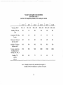
Viscosity-Graded Asphalt Cement Specification
ASTM D3381 TABLE 1
(used for NORMAL temperature pavements)
?-
AC2.5
AC-5
AC-10
AC-20
AC-40
Viscosity, 140F, P
250 ± 50
500 ± 100
1000 ± 200
2000 ± 400
4000 ± 800
Viscosity, 275F, min, cST
80
110
150
210
300
Penetration 77F, 100g
5 s, min
200
120
70
40
20
Flash point, Cleveland
open cup, min, F
325
350
425
450
450
Solubility in Trichloroethylene, min %
99.0
99.0
99.0
99.0
99.0
Tests on residue from
thin-film oven test:
viscosity, 140F, max, P
1250
2500
5000
10000
20000
Ductility, 77F, 5cm/sec
min, em
100
100
50
20
10
note: if ductility is less than 100, material will be accepted of
ductility at 60F is 100 minimum at a pull rate of 5 em/sec.
18
APPENDIXB
19
Viscosity-Graded Asphalt Cement Specification
ASTM D3381 TABLE 2
(used for LOW temperature pavements, where cracking is a concern)
AC2.5
AC-5
AC-10
AC-20
AC-30
AC-40
Viscosity, 140F, P
250 ± 50
500 ± 100
1000 ± 200
2000 ± 400
3000 ± 600
4000 ± 800
Viscosity, 275F, min,
cST
125
175
250
300
350
400
Penetration 77F, 100g
5 s, min
220
140
80
60
50
40
Flash point, Cleveland
open cup, min, F
325
350
·425
450
450
450
Solubility in Trichloroethylene, min %
99.0
99.0
99.0
99.0
99.0
99.0
Tests on residue from
thin-film oven test:
viscosity, 140F, max, P
1250
2500
5000
10000
15000
20000
Ductility, 77F,
5cm/sec
min, em
100
100
75
50
40
25
note: if ductility is less than 100, material will be accepted of
ductility at 60F is 100 minimum at a pull rate of 5 em/sec.
20
APPENDIX C
21
ASTM D 2041
Theoretical Maximum Specific Gravity of Bituminous Paving Mixtures ("Rice Method")
(abbreviated - does not cover pycnometer method)
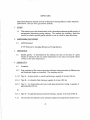
1. SCOPE
1.1
This method covers the determination of the theoretical maximum specific gravity of
uncompacted bituminous paving mixtures. The method also includes a rapid test
version for relative specific gravity suitable for use in a field or plant laboratory.
2. APPLICABLE DOCUMENT
2.1
ASTM Standard:
D 979 Methods for Sampling Bituminous Paving Mixtures
3. DEFINITION
3.1
Specific gravity - as determined by this method, the ratio of the mass of a given
volume of material at 25C (or stated temperature) to the mass of an equal volume
of water at the same temperature.
4. APPARATUS
4.1
Container:
4.1.1
Four variations of the vacuum saturation technique using containers of different size
and functional design are described. The container may be:
4.1.1.1 Type A - A glass, plastic, or metal bowl having a capacity of at least 1000 ml.
4.1.1.2 Type B - A volumetric flask having a capacity of at least 1000 ml.
4.1.1.3 Type C - An intermediate-size heavy wall glass pycnometer having a capacity of
approximately 4000 ml.
or
4.1.1.4 Type D - A large-size plastic pycnometer having a capacity of at least 10,000 ml.
4.1.2
The container size depends on the minimum sample size requirements as given in 6.2.
22
4.1.3
Containers shall be sufficiently strong to withstand an essentially full vacuum
and shall have covers as follows:
4.1.3.1 A cover fitted with a rubber gasket and a hose connection, for use with the bowl
(Type A).
4.1.3.2 A rubber stopper with a hose connection, for use with the volumetric flask (Type B).
4.1.3.3 A suitable vacuum connection assembly consisting of a vacuum gage, release valve,
and tubing connector, plus a tapered stopper device for maintaining consistent volume
regulation, for use with the pycnometer (Type Cor D).4.1.4 A small piece of fine
wire mesh covering the hose opening will minimize the possibility of loss of fine
material. Because of the mass involved, approximately 20 kg (44 lb), the large-size
pycnometer container (Type D) should be equipped with suitable handles to facilitate
transport and shaking while under vacuum to assist bubble release. Construction
should permit visual observation of the effects of vacuum and shaking.
4.2
Balance, with ample capacity, and with sufficient sensitivity to enable the specific
gravity of samples of uncompacted paving mixtures to be calculated to at least four
significant figures; that is, to at least three decimal places. For the bowl method
(Type A), the balance shall be equipped with a suitable suspension apparatus and
holder to permit weighing the sample while suspended from the center of the scale
pan of the balance.
4.3
Vacuum Pump or Water Aspirator, capable of evaluating air from the container to
a residual pressure of 30 mm Hg (4.0 kPa) or less. A water aspirator or vacuum
pump with less capability may be used for the rapid test version (Section 12).
4.4
Manometer or Vacuum Gage, suitable for measuring the specified vacuum.
4.5
Water Bath:
4.5.1
For Type A, B, or C containers, a constant-temperature water bath of suitable size
for the container to be used. For Type D, the large-size plastic pycnometer, no water
bath is required. 4.5.2 When using the weighing-in-water technique (7.4.1), a water
bath suitable for immersion of the suspended container and deaerated sample is
required.
4.6
Miscellaneous - A suitable trap (Erlenmeyer flask) installed in the line is
recommended to prevent water from entering the vacuum pump. Also, use of a
plastic twistcock valve in the line adjacent to the flask or pycnometer will minimize
loss of water during shaking and provide quick disconnection in case of foaming or
malfunction. For use with glass containers, a rubber or resilient plastic mat is
required as a safety precaution to avoid impact on a hard surface while under
vacuum.
23
6. SAMPLING
6.1
Obtain the sample in accordance with Method D979.
6.2
The size of the sample shall conform to the following requirements. Samples larger
than the capacity of the container may be tested a portion at a time.
Size of Largest Particle of Sample
Aggregate in Mixture, mm (in.)
Minimum Size, g
6000
4000
2500
2000
1500
1000
500
50.0(2)
37.5 (1 1/2)
25.4 (1)
19.1 (3/4)
12.5 (1/2)
9.5 (3/8)
4.75 (No.4)
7. PROCEDURE
7.1
Separate the particles ofthe sample, taking care not to fracture the mineral particles,
so that the particles of the fine aggregate portion are not larger than 6.4 mm (1/4
in.). If the mixture is not sufficiently soft to be separated manually, place it in a
large, flat pan and warm in an oven only until it can be so handled. See also Section
12, for alternative handling possible with the large-size plastic pycnometer (Type D).
7.2
Cool the sample to room temperature, place in a container, and weigh. Designate
the net mass of sample as A. Add sufficient water at approximately 25C (77F) to
cover the sample. With the large-size plastic pycnometer (Type D), the sample does
not have to be cooled and the added water at any convenient temperature may be
brought up into the domed lid about halfway to minimize evacuation time.
7.3
Remove entrapped air by subjecting the contents to a partial vacuum, 30 mm Hg (4
kPa) or less absolute pressure, for 5 to 15 min (see Note 5). (A partial vacuum of
30 mm Hg (4 kPa) absolute pressure is approximately equivalent to 730 mm Hg or
28.7 in. Hg reading on a vacuum gage at sea level.) Agitate the container and
contents either continuously by mechanical device or manually by vigorous shaking
at intervals of about 2 min. Glass vessels should be handled on a resilient surface,
such as a rubber or plastic mat, and not on a hard surface, to avoid impact while
under vacuum. Vacuum should be applied and released gradually by using the bleed
valve.
7.4
Immediately after removal of the entrapped air (7.3), proceed with one of the
following determinations:
24
7.4.1 Weighing in Water - Suspend the bowl (Type A) or flask (Type B) and contents in
the water bath and determine the mass after 10 min immersion. Measure the water
bath temperature, and if different from 25 C (77 1.8F) in the water bath. Determine
the mass of the container (and contents), completely filled in accordance with 5.2,
10 min after completing 7.3. Designate this mass as E.
7.4.3 Large-Size Plastic Pycnometer (Type D) Determination - Fill the pycnometer with
water of approximately the same temperature as the contents, inset the vented
stopper, and dry the outside using the same technique as in 5.3. The elapsed time
for gently pouring in the final water and drying shall be the same as the calibration
time within 1 min. Determine the mass of the pycnometer completely filled and
designate this total mass as G. Remove the vented stopper and record the
temperature of the water.
8.
CALCULATION
8.1
Calculate the specific gravity of the sample as follows:
8.1.1 Weighing in Water:
A
sp gr
=
(1)
A-C
where:
A
C
=
=
mass of dry sample in air, g, and
mass of sample in water, g.
25