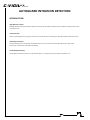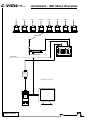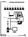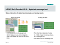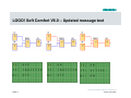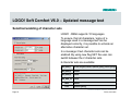
1
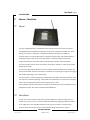
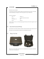
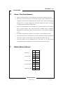
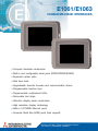
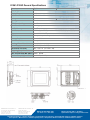
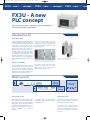
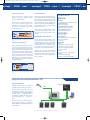
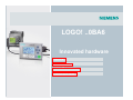
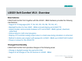
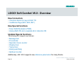
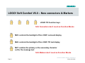
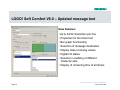
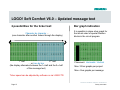
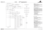
C-VIGILL T D : marine AUTOGUARD INTRUSION DETECTION C-VIGIL Ltd Registered in England & Wales: Company Registration No. 04407624 Digital House, Peak Business Park, Foxwood Rd, Chesterfield, Derbyshire, S41 9RF, UK. VAT Registration No. GB 804 6004 68 ISO 9001:2008 Registration No. GB 2001654 www.cvigil.co.uk C-VIGIL Ltd : marine Swbd: +44 (0)8432 898 464 T: +44 (0)1246 269 469 F: +44 (0)1246 351 288 E: [email protected] C-VIGILL T D : marine AUTOGUARD INTRUSION DETECTION INTRODUCTION High Risk Piracy Areas Strategically placed wireless PIR motion detectors will alert security staff to possible intrusions without exposing ship’s staff to unnecessary risks In Port Security Detect unwanted guests who try to gain access to your vessel. Protect the relatively un-patrolled outboard side of the vessel. Stowaway Prevention As the stowaway patrol is undertaken, deploy PIR motion sensors to protect areas already declared clear. Any further movements in these areas could well be stowaways. Crew Safety Monitoring Protect against inadvertent entry into unauthorised spaces i.e. confined spaces, paint lockers, cofferdam…etc. C-VIGIL Ltd C-VIGILL T D : marine AutoGuard – MK I Basic Overview AFT PORT AFT STBD AFT PORT MID STBD MID PORT FRD STBD FRD FRD PIR 1 PIR 2 PIR 3 PIR 4 PIR 5 PIR 6 PIR 7 PIR 8 Wireless Link RB External Antenna Ship’s Mains Base Station D-n-D* Interface *Optional D-n-D : - Drag-n-Drop D-n-D* PC NOT TO SCALE C-VIGIL Ltd C-VIGILL T D : marine AutoGuard – MK II Basic Overview AFT PORT AFT STBD AFT PORT MID STBD MID PORT FRD STBD FRD FRD PIR 1 PIR 2 PIR 3 PIR 4 PIR 5 PIR 6 PIR 7 PIR 8 Wireless Link RB External Antenna Ship’s Mains Base Station Splitter D-n-D* Interface Display & Control Panel F1 F2 F3 F4 ESC OK Security Station R On/Off Alarm Reset Alarm Test *Optional D-n-D: - Drag-n-Drop D-n-D* PC NOT TO SCALE C-VIGIL Ltd C-VIGILL T D : marine AutoGuard – MK III Basic Overview AFT PORT AFT STBD AFT PORT MID STBD MID PORT FRD STBD FRD FRD PIR 1 PIR 2 PIR 3 PIR 4 PIR 5 PIR 6 PIR 7 PIR 8 Wireless Link RB External Antenna Ship’s Mains Base Station Etc…Etc… Splitter Master Touch-screen Display Office D-n-D* Interface *D-n-D : - Drag-n-Drop Touch-screen Display Bridge Touch-screen Display Security Station Alarm Panel D-n-D* PC PLC Control Panel Stand-alone CCTV NOT TO SCALE C-VIGIL Ltd Part A AUTOGUARD Wireless Intrusion Detection System Part B AUTOGUARD Optional Drag-n-Drop System User Manual - Page 2 AUTOGUARD Part A AUTOGUARD Wireless Intrusion Detection System User Manual Intrusion Detection www.cvigil.co.uk C-VIGIL Ltd : marine [email protected] User Manual - Page 3 AUTOGUARD Contents SYSTEM DESCRIPTION .............................................................................................. 4 1.1 1.1.1 1.1.2 Detector Heads ................................................................................................................................... 4 General .......................................................................................................................................... 4 Detection Zones ................................................................................................................................ 5 1.2 Receiver / Base Station ........................................................................................................................ 6 1.2.1 General ...................................................................................................................................... 6 1.2.2 Alarm Outputs ............................................................................................................................. 6 1.2.3 System Code Transmission & Settings ............................................................................................... 7 1.2.4 Storage / Carry Case ................................................................................................................... 7 2. OPERATION & DEPLOYMENT............................................................................... 8 2.1 General ............................................................................................................................................ 8 2.2 Detector Deployment ......................................................................................................................... 8 2.3 Receiver / Base Station Deployment .................................................................................................... 9 3. DETECTOR BATTERY ENDURANCE ........................................................................ 9 Intrusion Detection www.cvigil.co.uk C-VIGIL Ltd : marine [email protected] User Manual - Page 4 AUTOGUARD System Description 1.1 Detector Heads 1.1.1 General Each detector head is a self-contained battery powered unit capable of transmitting a coded alarm signal to the central monitoring station. Any number of similarly coded heads or a repeater may be deployed in up to eight separate zones. Each sensor is capable of continuous operation for up to about 10 years (see Section 3. for battery endurance). Alarm response is by way of passive infra red detection (PIR). The active alarmed area is a 30m beam detection zone from the sensor faceplate. This gives excellent selective positioning control when deploying the units, for example, running along a ship’s open decks, across a hatch entrance way, gangway access point. The units have a protective faceplate that also acts as an on/off switch. Note: Environmental conditions may reduce effective operating distance Once the heads are actived they are ready for immediate deployment as and when required. Optimum detection is achieved when mounted approximately 2m above the deck and positioned so that target movement will be across the zone rather than towards or away from the unit. It is important to avoid situations where two or more heads can trigger simultaneously as this can corrupt the coded transmission to the base station. Once deployed the detection zones can be “walk-tested” using the base station on battery power. Note: Once activated the head has a reset time of approximately 5 seconds after movement has ceased. Detector heads should be tested/activated periodically otherwise after prolonged periods of inactivity the heads ‘go to sleep’ and will require the cover to be replaced to reset the detector. Intrusion Detection www.cvigil.co.uk C-VIGIL Ltd : marine [email protected] User Manual - Page 5 AUTOGUARD 1.1.2 Detection Zones The detection zones are indicated in the diagrams below: - 2m 2.4m 30m Detection Zone – Side View 3m 3m 30m Detection Zone – Plan View Intrusion Detection www.cvigil.co.uk C-VIGIL Ltd : marine [email protected] User Manual - Page 6 AUTOGUARD 1.2 Receiver / Base Station 1.2.1 General The unit is lightweight and is intended for mains operation but also contains an internal rechargeable battery capable of providing up to 36 hours of portable / standby use, “walktesting” for example. The battery is charged automatically during mains operation. The base station can also be powered by an external 12V DC supply, the internal battery is charged during this mode of operation (this facility is available to special order only). A single on/off switch, this illuminates the yellow power indicator next to the switch. The alarm sounder may be set to one of three modes ‘Off’, ‘Steady’ or ‘Pulse’ by way of the audible alarm switch. The nine bank LED display indicates an alarm condition by the individual zone numbers and remains illuminated until the reset switch is activated. The incoming alarm signal also triggers the sounder depending on the mode setting. The reset switch is used to extinguish any illuminated zone LEDs as and when required. It will also reset the low battery warning. The sounder will operate again if a new alarm is received from a zone already illuminated on the LED display prior to reset. The low Battery indicator illuminates on receipt of low battery warning transmitted by any of the detection heads. (See notes on Detector Head Batteries). 1.2.2 Alarm Outputs On the rear of the unit either a two pole terminal is fitted for providing a single common output for all alarms or a 15 pin socket is fitted for additionally supplying individual outputs for all eight alarms. The individual outputs can be used, for example, to position CCTV cameras, while the common alarm is suitable for activating existing alarm systems. Intrusion Detection www.cvigil.co.uk C-VIGIL Ltd : marine [email protected] User Manual - Page 7 AUTOGUARD Base Station Alarm Outputs:A universally normally open contact available via the two pole terminal posts. This output closes momentarily on receipt of a valid alarm signal from any of the 8 zones. 15 pin “D” Connector Pin 1 – 7 Alarms 1 – 7 Pin 9 Output common for all alarms Pin 8 & 10 – 14 N/C Pin 15 Alarm 8 These outputs are ‘clean’, normally open giving momentary closure when a signal is received from any zone 1.2.3 System Code Transmission & Settings On activation each Guardian detection head transmits two separate signal codes back to the base station. A third low battery code will be transmitted when required. 1.2.4 Storage / Carry Case When not in use the system may be stored in a hard sided case for protection and ease of transportation and deployment. Intrusion Detection www.cvigil.co.uk C-VIGIL Ltd : marine [email protected] User Manual - Page 8 AUTOGUARD 2. Operation & Deployment 2.1 General Guardian is a completely self-contained portable intruder detection system demanding minimal skill during deployment and subsequent operation. Capable of monitoring up to eight separate zones from a single monitoring unit it provides invaluable protection for a vast range of security operations where mobility and versatility are the prime operational requirements. The system is supplied in a robust protective case complete with the following items: - • A battery / mains operated base station monitoring unit complete with alarm outputs and integrated radio receiver. • Eight coded battery powered detection heads, for portable deployment on the ship as required, capable of transmitting a radio signal back to the base station giving location number of alarmed area • 2.2 Operating instructions Detector Deployment 1. Remove the detector from its carry case 2. Install the detector(s) in their final locations: i. On a suitable bracket on the ship’s structure / side rails ii. Free standing on its tripod base iii. Attached to a convenient point by the bungee cords 3. Remove the protective cover from the detector Intrusion Detection www.cvigil.co.uk C-VIGIL Ltd : marine [email protected] User Manual - Page 9 AUTOGUARD 2.3 Receiver / Base Station Deployment • Power-up the base station by connecting the mains lead into the back of the unit • Switch ‘On’ the base station, the mains LED will glow yellow indicating power is supplied to the unit (The charging LED may also glow if the internal rechargeable batteries are at a certain voltage level. This LED indicates the unit is also being charged; this will not effect the application. • With all or several detector units deployed, you may have several alarms showing, this is normal because they would have been activated during installation. Activating the reset button should clear these alarms, if not, check the detectors set-up. • It is always required that a ‘walk-test’ be carried out on each detector location. • Once the base station is activated you can choose whether you want the activation audio able or silent. In either mode the alarm LED will illuminate on alarm • The base station can be operated for up to 36 hours on its own internal rechargeable batteries, although it is normal to run the system from mains. 3. Detector Battery Endurance No Alarms 1 Alarm / 24h 2 Alarms / 24h 10 Alarms / 24h 24 Alarms / 24h Days Years 5606 15.36 Days Years 5461 14.96 Days Years 5323 14.58 Days Years 4431 12.14 Days Years 3443 9.43 Intrusion Detection www.cvigil.co.uk C-VIGIL Ltd : marine [email protected] User Manual - Page 10 AUTOGUARD Part B AUTOGUARD Optional Drag-n-Drop System Intrusion Detection www.cvigil.co.uk C-VIGIL Ltd : marine [email protected] Part B AUTOGUARD Drag-n-Drop Windows PIR Positioning Software User Manual Ver: 2.1.0.26 User Manual - Page 2 Drag-n-Drop Serial Numbers Example : 001 / 001 / 1701 Company Reference Ship Reference Part Number Please quote serial numbers in any correspondence. Intrusion Detection www.cvigil.co.uk C-VIGIL Ltd : marine [email protected] User Manual - Page 3 Drag-n-Drop Contents 1. Requirements 17 1.1 Hardware 17 1.2 Software 18 2. Installation 18 3. General Description 19 4. Operation 20 4.1 Opening Screen - First Run 20 4.2 PIR Deployment 20 4.3 Alarm Indication 21 4.4 Ship Outline Selection 21 4.5 Save Configuration Changes 22 On Screen Buttons & Menu Options 23 5.1 On Screen Buttons 23 5.1.1 PIR Icons 1 – 8 23 5.1.2 PIR Home 23 5.1.3 Speaker 24 5.1.4 Simulate Alarm 24 5.1.5 Reset All Alarms 24 5.1.6 Data Indication 25 5.1.7 Config File Function 25 5. 5.2 6. Menu Options 25 5.2.1 File 25 5.2.2 ComPort 26 5.2.3 Options 26 5.2.4 Tools 26 5.2.5 Custom 27 5.2.6 Help/About 28 First Line Fault Finding 29 Intrusion Detection www.cvigil.co.uk C-VIGIL Ltd : marine [email protected] User Manual - Page 4 Drag-n-Drop 1. Requirements 1.1 Hardware • • • • • • 1.2 Wireless receiver/base station Splitter - required if using more than one computer (up to 3 computers in total) Distribution panel (if using the fixed position portable panel) Drag-n-Drop interface panel (includes serial to USB adapter) Suitable PC or laptop with the following minimum system requirements (see below) Mouse or pointing device + keyboard Software MINIMUM COMPUTER SYSTEM REQUIREMENTS: • • • • • • • Software : Microsoft .NET Framework 4 (see below) Supported Operating Systems : Windows Server 2003; Windows XP; Windows Vista; Windows 7 Processor : 400MHz Pentium processor or equivalent (minimum); 1GHz Pentium processor or equivalent (recommended) RAM : 96MB (minimum); 256MB (recommended) Hard Disk : Up to 500MB of free space may be required CD or DVD Drive : Required Display : 800 x 600, 256 colours (minimum; 1024 x 768 high colour, 32-bit (recommended) MICROSOFT .NET FRAMEWORK GUARDIAN : Drag-n-Drop software is designed to operate within the Microsoft .NET Framework environment. • Microsoft .NET Framework 4 is installed automatically when GUARDIAN : Drag-n-Drop is installed (.NET Framework should already be installed with Windows O/S). • However, if for any reason this is not the case then Microsoft .NET Framework 4 can be installed manually from the CD Intrusion Detection www.cvigil.co.uk C-VIGIL Ltd : marine [email protected] User Manual - Page 5 Drag-n-Drop 2. Installation Please Note: The operating software should be installed on the same drive as Windows (usually C:) for the speaker to operate correctly. GUARDIAN : DRAG-n-DROP INSTALLATION • • • • Insert the CD into computer’s CD drive Depending on your computer’s CD drive’s settings the program should start automatically If this is not the case… o Open Windows Explorer or go to “My Computer” o Locate and double click on your CD drive o Locate and double click on file – AutoRun.exe o Enter serial number exactly as printed on the CD case front i.e. ***/***/**** o Select “Install Software” from the main menu o Select “Drag-n-Drop” from the sub-menu options o Select “.NET Framework” for the sub-menu options if necessary Please refer to the ReadMe for last minute release notes GUARDIAN : DRAG-n-DROP OPERATION • • • • During installation an icon will be added to your desktop Double click desktop icon or… From the Start menu go to All Programs – locate the program listed under EILAND COMMUNICATIONS LTD INTERFACE PANEL (INCLUDES SERIAL TO USB ADAPTER) Connecting the hardware to the PC… Under Windows Vista 1. Connect the Drag and Drop Interface to a USB port on your computer. 2. When the Found New Hardware appears select Locate and install driver software (recommended). 3. Insert the CD provided into you CD-ROM drive and click Next. 4. When the installation is done click Close. 5. A pop-up message will appear in the notification area indicating the installation is complete. Restart your computer if prompted to do so. Under Windows XP Note: DO NOT connect the Drag and Drop Interface to your computer before completing the driver installation. 1. Insert the CD provided into your CD-ROM drive. Run the Setup file under x:\Driver\Win98_XP where x: is your CD-ROM drive letter. When the welcome screen appears click Next. 2. Click Finish to complete the installation. 3. Once the installation is done connect the Drag and Drop Interface to a free USB port on your computer. Check in Control Panel , System , Device Manager then Ports (COM & LPT) that a port labelled Prolific USB-toSerial Comm Port (COMx) has appeared. Note its designation e.g. COM3. This is the port you should select from the drop down menu when running the client software. Intrusion Detection www.cvigil.co.uk C-VIGIL Ltd : marine [email protected] User Manual - Page 6 Drag-n-Drop 3. General Description The Drag-n-Drop option is a bolt-on to the GUARDIAN wireless motion detection system, the basic system having zone indication only. However, the basic system can easily be expanded to allow visual identification and simple interpretation of the detected point of intrusion. The Drag-n-Drop program allows you to customise the onscreen presentation to match your ship type and the layout of the PIR detectors. Holding down the mouse left button on the PIR icon will allow you to Drag-n-Drop the icon at a location on the ship outline co-incident with the actual physical location that you have place the PIR. On activation, the affected on screen PIR icon will flash red and an audible alarm will be heard (provided you have not muted the computer’s sound output). The alarm will continue till the operator accepts the condition, when the PIR icon will then turn steady red till the alarm is reset, if the PIR is reactivated during this period the alarm will be reinstated. Once the intrusion has been investigated the alarm should be reset, at this time the icon will return to green. Intrusion Detection www.cvigil.co.uk C-VIGIL Ltd : marine [email protected] User Manual - Page 7 Drag-n-Drop 4. Operation 4.1 Opening Screen – First Run Figure 1 : Main Screen When the program is first run, the basic un-configured main screen is displayed - see Figure 1, it can be seen that all the PIR icons are parked in the home position. If the interface panel is connected & installed correctly the red data icon will flash green. The speaker is turned on please ensure that the computer’s audio is not muted. 4.2 PIR Deployment Figure 2 : PIRs Deployed Intrusion Detection www.cvigil.co.uk C-VIGIL Ltd : marine [email protected] User Manual - Page 8 Drag-n-Drop PIR Deployment – during the physical deployment of the PIR motion detectors, make a note of where each PIR has been situated. Using the computer’s mouse, left click & hold on a specific PIR icon and then drag it to coincide with the actual physical position, do this for all the PIR’s being used – see Figure 2. Once in position, right click on the icon and from the new menu click on PIR label. Select a corresponding position from the drop down list; the selected position will now appear in the PIR position table. You can also add custom positions to the label list i.e. Main Deck Hatch Entrance No 1. From the Menu Options click on “Custom” Click on “Edit PIR Location List” Enter he PIR’s location and click Save. The custom position will now be added to the selectable list. This custom position will now be available when you right click the PIR icon and select Label. Once all the PIRs have been deployed click on the “Simulate Alarm” to test that the alarm function is operating correctly. A random PIR will be activated and the audible alarm sounded. Click on the “Reset All” button to begin using the system. The program can be run minimised if required, to allow the user access to other programs on the PC. Once the PIRs are no longer required and have been retuned to their storage case, click on the “PIR Home” button to return the PIR icons to their parked position. Intrusion Detection www.cvigil.co.uk C-VIGIL Ltd : marine [email protected] User Manual - Page 9 Drag-n-Drop 4.3 Alarm Indication Alarm Detection: If a PIR is activated the corresponding PIR icon will start to flash red and an audible alarm activated (provided the speaker is not muted). With the program minimised the taskbar tab flashes red to indicate an activation. In the maximised state the window panel also flashes. Alarm Acceptance: Right click on the flashing icon and click on “PIR Accept Alarm” the flashing red now turns steady red, audible alarm reset, window panel stops flashing. Alarm Reset: Right click on the red icon and select “PIR Reset” to return the icon to its normal state – steady green, or use the “Reset All” button to accept all active icons. 4.4 Ship Outline Selection Figure 3 : Ship Outline Selection To facilitate for differing hull forms and ship types it is possible to select an outline to correspond with your requirements. From the Options menu click on “Ship Type” then from the drop down menu select the most appropriate outline to match your requirements – see Figure 3. 4.5 Save Configuration Changes The current PIR icon positions can be stored for future use by clicking on the “Save” button, or they can be stored with a specific name using the “Save As” button – you will now be given the opportunity to save the configuration to a location of your choice. Intrusion Detection www.cvigil.co.uk C-VIGIL Ltd : marine [email protected] User Manual - Page 10 Drag-n-Drop 5. On-Screen Buttons & Menu Options The majority of the on-screen buttons have corresponding functions available through the menu options. For those who prefer – these menu functions have keyboard short cuts assigned. 5.1 On-Screen Buttons 5.1.1 PIR Icons 1 – 8 Drag-n-Drop PIR icons: can be positioned to correspond to actual PIR detector positions. 5.1.2 PIR Home Returns deployed PIR icons to parked position when not in use. Intrusion Detection www.cvigil.co.uk C-VIGIL Ltd : marine [email protected] User Manual - Page 11 Drag-n-Drop 5.1.3 Speaker Clicking on the speaker icon turns the audible output on/off (requires the computer’s speaker to be on) Speaker Off Speaker On 5.1.4 Simulate Alarm Simulates an actual PIR detector operation by randomly activating a PIR icon; useful for testing the volume of the audible alarm. 5.1.5 Reset All Alarms Reset all activated icons simultaneously. Intrusion Detection www.cvigil.co.uk C-VIGIL Ltd : marine [email protected] User Manual - Page 12 Drag-n-Drop 5.1.6 Data Indication Flashing green – Normal condition Flashing Red – Lost communication with interface panel. Clicking on the Data icon will reset the connection to the interface panel, which should restore communications 5.1.7 Config File Function Save: Saves current PIR icon deployment configuration Load: Loads last PIR icon deployment configuration Save As: Saves current PIR icon deployment configuration to a location/directory of your choice – opens up a new directory/file location window. Load From: Loads previously saved PIR icon deployment from the location/directory chosen – opens up a new directory/file window. 5.2 Menu Options The majority of on screen button operated functions are available through the menu options that include functions available as keyboard short cuts. The menu functions not already covered in the preceding sections are: - 5.2.1 File PIR Event Logging The program logs ALL events i.e. PIR5 activation, PIR5 Alarm Acceptance, PIR5 Alarm Reset…etc. This can be useful for post event analysis. Intrusion Detection www.cvigil.co.uk C-VIGIL Ltd : marine [email protected] User Manual - Page 13 Drag-n-Drop 5.2.2 ComPort When the interface panel is first installed Windows will assign a Com port for communicating with the program. When the program first starts, with the interface panel connected, it will look for the Com port assigned during installation, if for any reason this Com port is not found it can be selected from the drop down menu. 5.2.3 Options Ship Type Select the ship outline from the default list – basic ship types - or customise your own outline using basic Windows image editing tools. Once an image file has been prepared – see Custom section – it can be imported using the Custom Ship Type option. PC Speaker Toggle PC speaker on/off Load Config on Restart Loads present configuration after restarting the program – if not selected then the default settings will be loaded. Toggles option on/off. 5.2.4 Tools PIR Home Returns the PIR icons to their parked home position Reset All Alarms Resets any/all activated PIR icons to normal condition. Resets Locations to Unassigned Resets PIR icon location table to unassigned. Intrusion Detection www.cvigil.co.uk C-VIGIL Ltd : marine [email protected] User Manual - Page 14 Drag-n-Drop 5.2.5 Custom Edit PIR Location List You can add custom positions to the label list i.e. Main Deck Hatch Entrance No 1…etc. From the Menu Options click on “Custom” Click on “Edit PIR Location List” Enter he PIR’s location and click Save. The custom position will now be added to the selectable list. This custom position will now be available when you right click the PIR icon and select Label. Copy Ship Type (Layout) to Clipboard Clicking on this menu option, or right clicking on the ship outline, will copy the background ship outline image to Windows clipboard. You can now open your preferred image editor and paste the image for editing. Edit Ship Type (Layout) With MS Paint With this option, after copying the image to clipboard it will open MS Paint (default Windows image editor) to allow basic image editing. Provided for computer installations which don’t having bespoke image editors. Import Ship Layout Imports previously prepared jpeg background image. Intrusion Detection www.cvigil.co.uk C-VIGIL Ltd : marine [email protected] User Manual - Page 15 Drag-n-Drop 5.2.6 Help About Displays the program’s software version and the interface panel’s hardware version. Technical Manual User Manual & technical drawings in pdf format Intrusion Detection www.cvigil.co.uk C-VIGIL Ltd : marine [email protected] User Manual - Page 16 Drag-n-Drop 6. First Line Fault Finding Symptom The Com Port designation says COM0 or unable to open Com Port is displayed. Probable Cause Windows has changed the COM port designation since the last time the software was run. Remedial Action Select the COM port from the drop down menu. You can check the port in use in device manager to confirm the correct port. The data light is GREY Wrong COM port Select the COM port from the drop down menu. You can check the port in use in device manager to confirm the correct port. The COM Port is correct but the data light is RED Hardware Fault Click the data icon to reset the Interface Box then check the ‘About’ menu to see if the hardware version appears. If it appears as - ?.?? the Interface Box is either not working, the Com Port is not working (try uninstalling then re-installing) or you have selected the wrong Com Port Unable to open COM Port The software is open twice Close one of the applications Windows cannot create the file location for saving the Config Files Occurs in Windows Vista. Windows User Access Control prevents folder creation. Manually create the folder for the config files. PC Speaker not sounding even though enabled in software PC speaker failure or PC speaker volume turned down. Test the PC speaker by another means eg most PC ‘beep’ at power up. Check the volume control setting in the Windows Audio settings. Intrusion Detection www.cvigil.co.uk C-VIGIL Ltd : marine [email protected] User Manual - Page 17 Drag-n-Drop C-VIGIL Ltd : marine Digital House, Peak Business Park, Foxwood Rd, Chesterfield, Derbyshire, S41 9RF, UK. +44 1246 269 469 (Int tel) +44 1246 351 288 (fax) 08700 056 248 (UK tel) [email protected] www.cvigil.co.uk Intrusion Detection www.cvigil.co.uk C-VIGIL Ltd : marine [email protected] E1061/E1063 HUMAN MACHINE INTERFACES • Compact industrial construction • Built-in and configurable serial ports (RS232/RS422/RS485*) • Expansion option slots • Real time clock • Upgradeable terminal firmware and communication drivers • Programmable function keys • Programmable multicolored LEDs • Removable text strips • Ultra-thin display panel construction • High resolution display technology • Built-in 10/100MB Ethernet ports • Universal Serial Bus (USB) ports (host support) Discover the Many Facets of Mitsubishi Electric. The Power in Automation Solutions. E1061/E1063 General Specifications Model E1061 Display Type STN Display Size 5.7” Resolution/Pixels QVGA 320 x 240 Colors 65K Input Type Touch LED / Function Keys 20 / 22 Alarm Function 7 – 11 groups FLASH Memory 12 MB Serial Ports RS232 (9-pin DSUB), combined RS422/RS485 (25-pin DSUB) Ethernet One 10/100 Mbit TP-port USB Host One port for printer, keyboard, mouse, scanner. . . Memory Cards Not available Real-Time Clock Battery backed Housing / Front Material Cast aluminum Power Supply ±24 VDC (20 - 30 VDC) Dimensions mm (inch) 201 x 152 x 6 (7.9 x 6.0 x 0.2) Weight kg (lbs) 0.87 (1.9) Max. Current Draw Min. (Max.) 0.25A (0.45A) Ambient Temp V (H) 0 – 50°C (0 – 40°C) Mitsubishi Electric Automation, Inc. 500 Corporate Woods Parkway Vernon Hills, IL 60061 Phn: (847) 478-2100 Fax: (847) 478-2253 Mitsubishi Electric Automation, Inc. 4299 14th Avenue Markham, Ontario L3R 0J2 Phn: (905) 475-8989 Fax: (905) 475-7935 E1063 16 (Grayscale) Visit us at www.meau.com Effective October, 2006 • L-VH-06078 Specifications subject to change without notice. Automation Platforms™ • Industrial Computers • Programmable Logic Controllers • Human Machine Interfaces • SCADA • Software Servo Systems • Motion Control • Variable Frequency Drives • Computerized Numerical Controls • PC Based Control • Robots FX3U Prod.Lnch_en 30.10.2005 11:51 Uhr Seite 1 Product News EBG 161-EN FX3U MELSEC PLC A new PLC concept with more power and performance Increased I/O capacity for advanced network/system control Up to 4.5 times faster for quicker program response 5 times more data storage to make program construction easier 8 times more memory for larger and more complex programs FX3U_Prod.info_en.qxd 16.11.2005 14:43 Uhr Seite 2 FX3U a new PLC concept /// FX3U a new PLC concept /// FX3U a new PLC con FX3U - A new PLC concept The new FX3U CPU brings a combination of greater flexibility and increased performance to the FX Family. Introduction /// New high speed bus The FX3U design has increased the opportunity to configure the PLC directly for your needs. Following the standard FX Family configuration, the FX3U CPU can be expanded to the right hand side using a wide range of options. The FX3U has an enhanced communications bus that automatically switches into high speed mode for communication with new FX3U expansion modules. Full compatibility is still available with FX2N and FX0N expansion blocks, and when these are configured the FX3U automatically reduces the bus speed to suit. Adapters add flexibility A major design enhancement of FX3U is the new adapter expansion bus on the left hand side of the FX3U CPU. Through this bus users can add additional analog and temperature units as well as multiple communications and positioning blocks. However, the major benefit for the user is that the analog and positioning adapter units no longer require the use of the traditional To/From instructions to configure and operate. The FX3U can use new FX3U blocks as well as standard FX2N and FX0N expansion blocks. FX3U has a unique new system of directly programmable adapters. All control is through direct access data registers and setting bits. This means quicker set-up, easier use, and above all much higher processing speeds. What’s new /// FX3U Base Unit A Expansion I/O Maximum + Network master B Remote I/O 256 I/O Remote I/O Remote I/O Remote network stations Maximum System Maximum 384 I/O A + B 384 256 I/O FX3U provides additional I/O and networking capacity. Increased I/O capacity With enhanced networking functions, the FX3U requires an increased input/output (I/O) range. FX3U can support systems with combined local I/O and networked I/O up to a total of 384 I/O points. For users, this means increased system control and added possibilities for advanced networks. Up to 4.5 times faster In addition FX3U also fully supports Profibus/DP as well as Ethernet using TCP and UDP protocols. This means the PC MIX value has been greatly improved with basic instructions now being processed in 0.065µsec. For users this means quicker program response and more accurate process performance as inputs, outputs and actions are processed and monitored more times per second. FX3U_Prod.info_en.qxd 29.11.2005 15:00 Uhr Seite 3 oncept /// FX3U a new PLC concept /// FX3U a new PLC concept /// FX3U a ne 8 times more memory 75 new instructions FX3U comes with a standard internal memory of 64k steps, which is 8 times more memory than FX2N. The FX3U has 75 new instructions in comparison with FX2N.This now makes available 209 instructions for program creation. All of the instructions follow the traditional FX Applied instruction concept designed to make the task of application building and program writing easier and quicker, with less chance for errors. More memory means users can write larger and more complex programs, store more data in file registers, or take greater advantage of using IEC 61131-3 style programming tools. New instructions include greater control over data processing with a range of new comparison and string manipulation commands. Simple high speed positioning FX3U provides increased performance in all areas. 5 times more data storage With a larger program memory comes the need for more operational devices such as timers, state flags, auxiliary relays and data registers. The FX3U has increased capacity in all of these major areas making program construction easier. Data register capacity has increased by a factor of 5 reflecting the needs of users who have an increased requirement to log operation information against products or batches of products being manufactured. The FX3U has been designed with six high speed counters that can each count up to 100kHz simultaneously per channel. This, combined with three 100kHz pulse train outputs, means users can directly configure simple 3-axis positioning systems without the use of additional modules. However, the new High Speed Counter ADP and Pulse train ADPs can provide the FX3U with maximum positioning performance. Each unit can process signal speeds of up to 200kHz. FX3U at a glance I/O range 16 – 384 (Discrete I/O, maximum 256) Program memory 64k steps (standard) Basic instruction processing 0.065µsec/logical instruction Analog signal processing Up to 80 analog inputs, 48 analog outputs Analog resolution 8, 12 and 16 bits Analog options 14 analog input, output and temperature blocks available for selection Positioning Internal: 6 high speed counters (100kHz) 2 high speed counters (10kHz) 3 pulse train outputs (100kHz), transistor unit only External: High speed counter ADP module (200kHz) Pulse train ADP (200kHz) Pulse train output block (1MHz) FX3U provides increased performance in all areas. Improved communications /// A great communicator FX3U has strengthened the communications capability of the FX Family even further. GOT1000 RS 232 The new adapters allow up to three RS communication channels to be operated simultaneously allowing multiple HMIs to be connected to a single FX3U CPU or combinations of HMIs, third party devices and programming tools – the choice is yours. The FX3U also supports a wide range of network options including AS-interface, Profibus/DP,CC-Link,DeviceNet,CANopen as well as Ethernet. RS 422 USB RS 485 Inverter multidrop Inverter 1 FX3U has a range of flexible communication options. Inverter 8 FX3U Prod.Lnch_en 30.10.2005 11:52 Uhr Seite 4 Specifications /// Specifications FX3U I/O points (addresses) Max. total 384 (with remote I/O) Address range Max. 256 direct addressing and max. 256 network I/O Program memory 64,000 steps RAM (internal), exchangeable FL-ROM for easy program exchange Cycle period 0.065 µs /basic instruction Number of instructions 27 sequence instructions, 2 step ladder instructions, 209 applied instructions Programming language Step ladder, instruction list, SFC and IEC61131-3 languages using GX IEC Developer Program execution Cyclical execution, refreshmode processing Internal relays 7680 Special relays 512 State relays 4096 Timer 512 Counter 235 High-speed counter 8 points 1 phase (6 points max. 100kHz, 2 points max. 10 kHz); 2 points 2 phase max. 50kHz Real-time clock Year, month, day, hour, minute, second, weekday Data register 8000 File register 32768 Index register 16 Special register 512 Pointer 4096 Nestings 8 Interrupt inputs 6 Communication options Ethernet (TCP/UDP), Profibus-DP, CC-Link, DeviceNet, CANopen, AS-interface, RS 485, RS 232, USB EUROPEAN BRANCHES EUROPEAN REPRESENTATIVES MITSUBISHI ELECTRIC EUROPE B.V. 25, Boulevard des Bouvets F-92741 Nanterre Cedex Phone: +33 1 55 68 55 68 FRANCE MITSUBISHI ELECTRIC EUROPE B.V. Gothaer Straße 8 D-40880 Ratingen Phone: +49 (0) 2102 / 486-0 GERMANY GEVA GmbH AUSTRIA Wiener Straße 89 AT-2500 Baden Phone: +43 (0) 2252 / 85 55 20 UTU Elektrotehnika AS Pärnu mnt.160i EE-11317 Tallinn Phone: +372 (0) 6 / 51 72 80 TEHNIKON Oktjabrskaya 16/5, Ap 704 BY-220030 Minsk Phone: +375 (0)17 / 210 4626 Beijer Electronics OY FINLAND Ansatie 6a FIN-01740 Vantaa Phone: +358 (0) 9 / 886 77 500 UAB UTU POWEL Savanoriu pr.187 LT-2053 Vilnius Phone: +370 (0) 52323-101 LITHUANIA INTEHSIS SRL Cuza-Voda 36/1-81 MD-2061 Chisinau Phone: +373 (0)2 / 562 263 MOLDOVA BELARUS ESTONIA SIA POWEL Lienes iela 28 LV-1009 Riga Phone: +371 784 / 22 80 ROMANIA GTS TURKEY Darülaceze Cad.No.43 Kat.2 TR-80270 Okmeydani-Istanbul Phone: +90 (0) 212 / 320 1640 Elektrostyle Poslannikov Per., 9, Str.1 RU-107005 Moscow Phone: +7 095 542 4323 INEA SR d.o.o. SERBIA AND MONTENEGRO Karadjordjeva 12/260 SCG-113000 Smederevo Phone: +381 (0)26/ 617 - 163 CSC Automation Ltd. UKRAINE 15, M.Raskova St., Fl.10, Office 1010 UA-02002 Kiev Phone: +380 (0) 44 / 494 3355 Elektrostyle RUSSIA Krasnij Prospekt 220-1, Office No.312 RU-630049 Novosibirsk Phone: +7 3832 / 106618 AutoCont Control s.r.o. Radlinského 47 SK-02601 Dolný Kubín Phone: +421 435868 210 SLOVAKIA Kazpromautomatics Ltd. KAZAKHSTAN 2, Scladskaya Str. KAZ-470046 Karaganda Phone: +7 3212 50 11 50 ICOS Ryazanskij Prospekt, 8A, Off.100 RU-109428 Moscow Phone: +7 095 232 0207 RUSSIA Koning & Hartman B.V. NETHERLANDS Haarlerbergweg 21-23 NL-1101 AK Amsterdam Phone: +31 (0)20 / 587 76 00 INEA d.o.o. Stegne 11 SI-1000 Ljubljana Phone: +386 (0) 1-513 8100 SLOVENIA Avtomatika Sever Ltd. Lva Tolstogo Str.7, Off.311 RU-197376 St Petersburg Phone: +7 812 1183 238 RUSSIA NPP Uralelektra Sverdlova 11A RU-620027 Ekaterinburg Phone: +7 34 32 / 532745 RUSSIA RUSSIA LATVIA Sirius Trading & Services srl Str.Biharia No.67-77 RO-013981 Bucuresti 1 Phone: +40 (0) 21 / 201 1146 RUSSIA IRELAND Koning & Hartman B.V. BELGIUM Researchpark Zellik, Pontbeeklaan 43 BE-1731 Brussels Phone: +32 (0)2 / 467 17 44 UTECO A.B.E.E. 5, Mavrogenous Str. GR-18542 Piraeus Phone: +302 (0) 10 / 42 10 050 MITSUBISHI ELECTRIC EUROPE B.V. Via Paracelso 12 I-20041 Agrate Brianza (MI) Phone: +39 039 6053 1 ITALY TELECON CO. BULGARIA Andrej Ljapchev Lbvd.Pb 21 4 BG-1756 Sofia Phone: +359 (0) 2 / 97 44 05 8 Meltrade Ltd. Fertõ Utca 14. HU-1107 Budapest Phone: +36 (0)1 / 431-9726 MITSUBISHI ELECTRIC EUROPE B.V. Carretera de Rubí 76-80 E-08190 Sant Cugat del Vallés Phone: +34 9 3 / 565 3131 SPAIN AutoCont CZECH REPUBLIC Nemocnicni 12 CZ-702 00 Ostrava 2 Phone: +420 59 / 6152 111 Ilan & Gavish Ltd. 24 Shenkar St., Kiryat Arie IL-49001 Petah-Tiqva Phone: +972 (0) 3 / 922 18 24 ISRAEL Beijer Electronics A/S Teglverksveien 1 N-3002 Drammen Phone: +47 (0) 32 / 24 30 00 NORWAY Beijer Electronics AB Box 426 S-20124 Malmö Phone: +46 (0) 40 / 35 86 00 SWEDEN Consys Promyshlennaya St.42 RU-198099 St Petersburg Phone: +7 812 325 3653 RUSSIA STC Drive Technique Poslannikov Per., 9, Str.1 RU-107005 Moscow Phone: +7 095 790 7210 MITSUBISHI ELECTRIC EUROPE B.V. Travellers Lane GB-Hatfield Herts. AL10 8 XB Phone: +44 (0) 1707 / 27 61 00 UK louis poulsen Geminivej 32 DK-2670 Greve Phone: +45 (0) 70 / 10 15 35 TEXEL Electronics Ltd. Box 6272 IL-42160 Netanya Phone: +972 (0) 9 / 863 08 91 ISRAEL MPL Technology Sp.z o.o. ul.Sliczna 36 PL-31-444 Kraków Phone: +48 (0) 12 / 632 28 85 POLAND ECONOTEC AG SWITZERLAND Postfach 282 CH-8309 Nürensdorf Phone: +41 (0) 1 / 838 48 11 Electrotechnical Shetinkina St.33, Office 116 RU-630088 Novosibirsk Phone: +7 3832 / 119598 RUSSIA CBI Ltd. SOUTH AFRICA Private Bag 2016 ZA-1600 Isando Phone: +27 (0) 11/ 928 2000 MITSUBISHI ELECTRIC EUROPE B.V. Westgate Business Park, Ballymount IRL-Dublin 24 Phone: +353 (0) 1 / 419 88 00 DENMARK GREECE HUNGARY Mitsubishi Electric Europe B.V. /// FA - European Business Group /// Gothaer Straße 8 /// D-40880 Ratingen /// Germany Tel.: +49(0)2102 4860 /// Fax: +49(0)2102 486112 /// [email protected] /// www.mitsubishi-automation.com Specifications subject to change without notice /// Art-Nr. 166508-A /// 10.2005 Factory Automation SIMATIC LOGO! ..0BA6 Colin Limbert Factory Automation Department Product Manager LOGO! and S7-200 LOGO! ..0BA6 Innovated hardware Overview Innovated inputs LOGO! TD text display 3 new plug-in cards LOGO! ..0BA6 – Overview LOGO! ..0BA6 hardware series provides the following new features: Innovated inputs for LOGO! 24(o) and LOGO! 12/24RC(o) LOGO! TD text display Backlight function for LOGO! on-board display + LOGO! TD (permanently on/off or controlled by user program) 3 new plug-in cards (memory card, battery card, combined card) 10 menu languages: (EN, IT, NL, ES, FR, CN, DE, TR, RU, JP*) Extended memory – 200 FB´s *) Japanese menu texts will be implemented in a E-stand change in 10/08 © Siemens AG 2008 – Subject to modifications Page 3 Factory Automation LOGO! ..0BA6 – Innovated inputs LOGO! 24(o), 12/24RC(o) now with 4 fast inputs and 4 analog inputs on-board AI3 AI4 Fast Counter Inputs AI1 AI2 LOGO! versions with DC power supply now offer: 4 fast counter inputs (for frequency up to 5 kHz) I3, I4, I5, I6 4 analog inputs (0-10V) I1=AI3 I2=AI4 I7=AI1 I8=AI2 4x 5kHz 4x AI (0-10V) for DC versions In LSC V6.0 you must defined weather 2 or 4 integrated analog inputs are to be used. © Siemens AG 2008 – Subject to modifications Page 4 Factory Automation LOGO! ..0BA6 – New separated text display LOGO! TD LOGO! TD text display LOGO! ..0BA6 provides a new text display LOGO! TD. The LOGO! TD extends the display and user interface capabilities of all LOGO! basic modules. LOGO! Soft Comfort V6.0 provides configuration of the following LOGO! TD features: Power-on screen Function keys Message texts Backlight function © Siemens AG 2008 – Subject to modifications Page 5 Factory Automation LOGO! ..0BA6 – New separated text display LOGO! TD LOGO! TD text display Power Supply: 12V DC, 24V AC/DC unipolar power supply connector Features: 4 lines with 12 characters per line connectable to all ..0BA6 basic modules via a new interface socket Special connection cable is delivered with the LOGO! TD 6 standard keys and 4 additional function keys (F1-F4) IP65 protection class List price £89.00 (incl. cable) © Siemens AG 2008 – Subject to modifications Page 6 Factory Automation LOGO! ..0BA6 – 3 new cartridges LOGO! ..0BA6 supports 3 new cartridge: LOGO! Memory cartridge (violet colour) (single memory card with doubled memory – 32K) LOGO Battery cartridge (green colour) (single battery card, supports RTC power supply up to 2 years) (Back up for Clock without a battery is 80 hours at 25°C) LOGO! Memory / Battery cartridge (brown colour) (combined memory / battery card) Note: LOGO! ..0BA6 still supports the brown memory cartridge from 0BA4/0BA5 (read, not write). i.e. Transfer Cartridge > LOGO! © Siemens AG 2008 – Subject to modifications Page 7 Factory Automation LOGO! ..0BA6 Innovated software Overview New functionalities of LSC V6.0 New function blocks Updated message text LOGO! Soft Comfort V6.0 - Overview New features LOGO! Soft Comfort V6.0 together with the LOGO! ..0BA6 hardware provides the following new features: Support of 10 languages (EN, IT, NL, ES, FR, CN, DE, TR, RU, JP) Backlight function for the LOGO! ..0BA6 on-board display and LOGO! TD Analog modem communication between a PC and LOGO! ..0BA6 (upload, download, online-test) Online status for LAD circuit programs Display of PI controller analog output value in a trend view during simulation or online test Method to delete user program with password in LOGO! ..0BA6 over LOGO! Soft Comfort Power-on screen for the LOGO! TD Changed functionality LOGO! Soft Comfort V6.0 provides changes in the following areas: Change in daylight savings time period for USA Support of all changes in the I/O structure in LOGO! ..0BA6 © Siemens AG 2008 – Subject to modifications Page 9 Factory Automation LOGO! Soft Comfort V6.0 - Overview New Connectors 4 function blocks for keys LOGO! TD 3 additional flags (M25, M26, M27) New Special functions Pulse Width Modulator (PWM) Analog Math FB and a separate Error detection FB Updated Special functions The following FB´s support new features: Message text PI-controller Operation hours counter Weekly timer Yearly timer Analog watchdog Up/down counter Additionally, LSC V6.0 supports new reference parameters for many blocks. © Siemens AG 2008 – Subject to modifications Page 10 Factory Automation LOGO! Soft Comfort V6.0 – New connectors & Markers LOGO! TD Function keys N.B. Connectors don’t count as Function Blocks M25: controls the backlight of the LOGO! on-board display M26: controls the backlight of the LOGO! TD text display M27: enables the primary or the secondary character set for the message text N.B. Markers don’t count as Function Blocks © Siemens AG 2008 – Subject to modifications Page 11 Factory Automation LOGO! Soft Comfort V6.0 – New FBs: Pulse Width Modulator (PWM) The PWM function modulates the analog input value Ax into a digital output signal. The pulse width is proportional to the analog value Ax. © Siemens AG 2008 – Subject to modifications Page 12 Factory Automation LOGO! Soft Comfort V6.0 – New FBs: Analog Math and Analog Math Error Detection Analog Math With this new function basic arithmetic operations are possible ( + , - , x , / ) . The result is an internal analog value (-32768 - +32767). Analog Math Error Detection With this new function it’s possible to handle both error cases of the Analog Math FB: Overflow Division by zero © Siemens AG 2008 – Subject to modifications Page 13 Factory Automation LOGO! Soft Comfort V6.0 – Updated message text New features: Up to 24/32 characters per line Properties for the ticker text Bar graph functionality Selection of message destination Display state of analog values Digital I/O states Selection / enabling of different character sets Display of remaining time of all timers © Siemens AG 2008 – Subject to modifications Page 14 Factory Automation LOGO! Soft Comfort V6.0 – Updated message text 2 possibilities for the ticker text: Bar graph indication Character by character … (one character after another tickers through the display) It is possible to place a bar graph for the actual value of special function blocks in the circuit program. 1st half 2nd half … or Line by line (the display alternates between the 1st half and the 2nd half of the message text) Placement: Horizontal / Vertical Max. 32 bar graphs per project Max. 4 bar graphs per message Ticker speed can be adjusted by software or via LOGO! TD © Siemens AG 2008 – Subject to modifications Page 15 Factory Automation LOGO! Soft Comfort V6.0 – Updated message text Status indication of digital inputs/outputs and analog inputs Digital I/O state 4 I/O states in one message text 20 I/O states in one circuit diagram User can define his own text for each state Analog AI state The internal analog input value 0…1000 of any AI can be shown in a message text 2 AI values in one message text © Siemens AG 2008 – Subject to modifications Page 16 Factory Automation LOGO! Soft Comfort V6.0 – Updated message text © Siemens AG 2008 – Subject to modifications Page 17 Factory Automation LOGO! Soft Comfort V6.0 – Updated message text Selection/enabling of character sets LOGO! ..0BA6 supports 10 languages. To ensure, that all characters / signs of a language used in a message text can be displayed correctly, it is possible to activate an alternative character set. In a message 2 text character sets can be enabled. By using new flag M27 the user can switch between the 2 character sets. 6 character sets are available: ISO_8859_1 German, English, Italian, Spanish (partly), Dutch (partly) ISO_8859_5 Russian ISO_8859_9 Turkish ISO_8859_16 French GBK Chinese SJIS Japanese (partly) © Siemens AG 2008 – Subject to modifications Page 18 Factory Automation