1
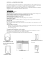
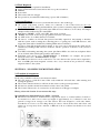
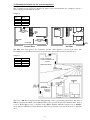
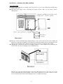
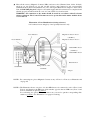
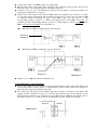
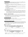
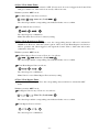
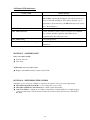
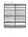
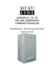
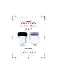
The most user friendly
Security Alarm System
LS400
Contents
Section 1 – Overview of System
1.1 Kit Contents
1.2 Tools Required
1.3 System Features
Section 2 – Planning your Installation
2.1 Location of components
2.2 Planning the location for the system components
Section 3 – Installing the System
3.1 Control Unit
3.2 Movement Detector/PIR
3.3 Door/Window Contact Detector
3.4 External Siren
3.5 Testing the System
Section 4 – Using the System
4.1 User PIN and Duress PIN
4.2 Changing the User PIN & Duress PIN
4.3 Set / Clear chime Zones
4.4 Set / Clear Home-Bypass Zones
4.5 Set / Clear bypass Zones
4.6 Display bypass Zones
4.7 Display Zones with faulty devices
4.8 Display Home-Bypass Zones
4.9 Set delay time
4.10 Set siren duration time
4.11 Walk Test command
4.12 Clear the Alarm Hold Indications
4.13 Panic alarm
4.14 Silencing the System
4.15 Arm (set) the Alarm System while Exiting the House
4.16 Disarm (unset) the Alarm System while Entering the House
4.17 Arm (set) the Alarm System when you are Inside the House
4.18 Summary of the zones in different mode
4.19 Summary of Factory Settings
4.20 Status LED indications
Section 5 – Maintenance
Section 6 – Extending the System
Section 7 – Troubleshooting
Section 8 – Specifications
SECTION 1 – OVERVIEW OF SYSTEM
The LS400 is an indoor alarm system based on our patent technology to give exceptional levels of
protection and reliability. It is a fuseless system with special electronic circuitry for short-circuit
protection. It is simple to use, easy to install, no special tools or training is required.
IMPORTANT – Please read this manual carefully, in full, before commencing Installation. You will find
installation easier if you follow these steps in the sequence shown.
1.1 Kit Contents
The system comprises of:
★ CONTROL UNIT
This main unit receives signals from detectors, accepts input from users and activates warning devices.
★ MOVEMENT DETECTOR PASSIVE INFRA-RED (PIR) (Two units)
It senses body heat of moving person; one unit may cover entire room.
★ DOOR/WINDOW CONTACT (Four pairs)
Uses a magnetically operated switch to sense the opening of door or window.
★ EXTERNAL SIREN
Gives audible indication of an alarm condition to warn people who are away from the Control Unit.
★ ADAPTOR
For mains supply to the Control Unit and the system.
N.B. The adaptor supplied with this kit is CE approved. If other adaptor is used, make sure it is a CE
approved type.
The alarm kit also contains:
-
50 meters of two-core flat wire and clips for wiring the detectors and external siren to the Control unit.
N.B. This wire MUST NOT be used for mains connections.
Screw/ wall plug packs.
To complete your installation, you also require:
Eight pieces 1.5V “AA” alkaline batteries for fitting inside Control Unit as back-up power source so
as to maintain system functions in the event of main power failure.
The batteries are not included in your kit, and need to be purchased separately.
DOOR/WINDOW CONTACTS
MOVEMENT DETECTOR
PASSIVE INFRA-RED (PIR)
(Four pairs)
(Two units)
CONTROL UNIT
ADAPTOR
EXTERNAL SIREN
-2-
1.2 Tools Required
The following tools are required for installation:
★ Large & small flat bladed screwdrivers and cross point screwdrivers
★ Hammer
★ Power drill
★ Wire cutters and wire stripper
★ Eye protection (recommended when using a power drill or hammer)
1.3 System Features
★ Simple and effective Four-zone system with the new two-wire technology.
★ All system components (sensors, sirens) are connected to the Control Unit via two-core
non-polarity flat wires. Wiring and installation of the system is extremely simple and easy.
★ Control Unit has built-in keypad with status LEDs and zone indicators. Low battery and tamper
attempts will be indicated by the status LEDs.
★ Push-button “HOME”, “OUT” and “OFF” three mode operation.
★ “HOME” and “OUT” modes are pre-programmed for user convenience.
★ At “OFF” mode, door chime function is available.
★ All sensors, sounders are 24 hour line-protected and fully supervised. Any attempt to interfere
with the system, such as cutting the connecting wires or opening any of the PIR detectors, will
trigger the alarm and be identified by flashing LEDs and zone indicator.
★ No fuse to burn. Short-circuit tamper attacks to any zone sensor will trigger the alarm and be
identified by flashing LEDs and zone indicator, but the operation of the rest of the system is
protected.
★ User PIN for disarming (unsetting) the system, plus Duress PIN to also dial out a telephone dialer
(if one is fitted) when entering the premises under duress.
★ Individual zones can be set to “HOME-BYPASS” or “BYPASS”; for example, the up-stairs
detectors can be set to “HOME-BYPASS” at night.
★ Two PIR motion detectors can be connected to one zone, therefore the system can be expanded to
have four PIRs plus many magnetic contacts. Also, easy connections are provided for adding
telephone dialer to the system.
SECTION 2 – PLANNING YOUR INSTALLATION
2.1 Location of components
Control Unit – Location
In choosing a suitable location you should bear in mind:
★ The user needs to reach the Control Unit easily within the allocated time, when entering and
leaving the premises.
★ The Control Unit should not be visible from the exterior of the protected premises.
★ All detectors and the external siren must be wired to the Control Unit.
★ The Control Unit needs to be connected to an AC main via a CE approved adapter.
Having chosen the location do not mount at this stage.
Movement/Passive Infra Red Detector (PIR) – Location
★ The detector should not be mounted near to large metal objects or on metal surfaces. It needs to
be mounted on a wall or in a corner at a height of approximately 2 to 2.5meters for the best
general coverage in an average room. The detector has been designed to avoid false alarms,
nevertheless, it is best to avoid looking directly at sources of heat such as fires and boilers, and
always try to keep away from a window. A PIR can look at a radiator but should not be sited
above one.
-3-
★ Do not site a PIR where its field of view may be obstructed (e.g. by curtains). Also note that PIRs
work best when sensing movement across rather than along their detection beams. You need to
consider the need to wire these units back to the Control Unit.
Detection Area of PIR
Having chosen the location do not mount at this stage.
Door/Window Contact Detectors – Location
★ Door/ Window Contact Detector is designed to detect a door or window
opening, so it is better mounted onto the frame with a magnet mounted next to
it on the door or window.
★ In most applications one door contact is fitted to the front door and assigned to
ZONE 1 which is the Entry/Exit Zone. When the system is set at “OUT” mode,
Zone 1 allows a 30 second (adjustable) delay for the user to enter or leave the
house, and should be the only zone activated before reaching the Control Unit
on entering the premises. The other contact detector can be mounted to the
back door or window and assigned to Zone 2.
Having chosen the location do not mount at this stage.
External Siren – Location
★ Choose a location for the siren box, preferably in a prominent position
high up on an external wall, taking into account that it must be wired
back to the Control Unit. The cable should ideally run directly from behind
the siren box through the wall to the inside. This is to avoid any cable
running along the exterior wall which could be reached by an intruder.
Having chosen the location do not mount at this stage.
-4-
2.2 Planning the location for the system components
Example of a domestic layout
The 2 sample layouts below are intended as guides only but demonstrate two examples of how a
house can be protected with the system.
Sample 1:
Zone
Area
1
2
3
4
Front Door
Back Door
Downstairs
Upstairs
DOOR/ WI NDOW
CONTACT DETECTOR
( ZONE1)
R
PI
DI NI NG ROOM
ZONE4
LS400
CONTROL
UNI T
BEDROOM
#1
KI TCHEN
ZONE3
R
PI
LI VI NG ROOM
BEDROOM
#2
DOOR/ WI NDOW
CONTACT DETECTOR
( ZONE2)
BEDROOM
#3
EXT.
SI REN
Ground Floor
2nd Floor
The PIRs have been placed one downstairs and the other upstairs to protect both areas. The
Door/Window Contact Detectors have been positioned to protect the front door and back door.
Sample 2:
Zone
Area
1
2
3
4
Front Door
Back Door
Living Room
Bedroom
DOOR / WINDOW
CONTACT DETECTOR
(ZONE 1)
ENTRANCE HALL
ZONE 3
LS400
CONTROL UNIT
DOOR / WINDOW
CONTACT
DETECTOR
(ZONE 2)
The Zone 3 PIR has been placed in the Dining/Living room to protect this general area. The Zone 4
PIR has been placed in Bedroom #1 (Master Bedroom) to protect the personal valuables there. Zone 4
is set as “Home-Bypass zone” so that the zone 4 PIR is disabled when the system is set at “HOME”
mode. The Door/Window Contact Detectors have been positioned to protect the front door and back
door.
-5-
SECTION 3 – INSTALLING THE SYSTEM
3.1 Control Unit
★ Remove and retain the two holding screws from front cover of Control Unit and carefully hinge
off the front cover.
★ Disconnect the battery snap connecting the battery holder. Take out the battery holder.
(Illustration 1)
Illustration 1
★ Place the Control Unit Mounting Template Sheet on the wall at the chosen location. Mark and
drill holes for the three mounting screws. Put in the wall plugs and have the two mounting screws
at the top (the hanging screws) inserted, leaving the two screws to protrude by about 5mm.
★ Aligning the Control Unit with the mounting guidelines on the template sheet and hang the
Control Unit onto the two hanging screws. (Illustration 2)
N.B. Do not put in the third mounting screw (the final fixing screw at the lower part of the
Control Unit) until after all the wirings to the Control Unit have been done, because you may
need to take the Control Unit off the hanging screws to facilitate the wiring.
-6-
★ Have all the sensors (Magnetic Contacts, PIRs) and accessories (External siren, dialer, if fitted)
wired up (as per Section 3.2, 3.3 and 3.4 that follows) and connected to the corresponding
terminals in the Control Unit (Illustration 3). Also wire up the Main Power Adaptor to the Control
Unit, but DO NOT plug in the adaptor to the main supply until all connections are completed and
all units properly mounted and front cover of Control Unit closed and secured.
WARNING: All connection to the mains should be made in accordance with all relevant
wiring regulations. The Control Unit must never be operated from the mains with the front
cover removed.
Illustration 3: Part Identification (wiring reference)
* All connections are simply by 2 non-polarity flat wires only.
Zone Indicators
Magnetic Contact in Zone 1
( NOTE 1 )
Power Indicator
Magnetic Contact in Zone 2
2-Wire PIR in Zone 3
( NOTE 2 )
2-Wire PIR in Zone 4
External Siren
Status LEDs
Enlarged View of the
Terminals
Adaptor
NOTE 1: For connecting two pieces Magnetic Contacts to any of Zone 1 or Zone 2, see Illustration 10
on page 10.
NOTE 2: The Illustration shows one piece of 2-wire PIR detector is connected to each of Zone 3 and
Zone 4; and therefore the PIR zone slide switches opposite the two PIR zone (Zone 3 and
Zone 4) terminals are put in position 1.
For connecting two pieces PIR to the same zone, you need to put the corresponding slide
switch to position 2. See Illustration 7 on page 9 for wiring.
-7-
★ After all the wirings are done, put in the final fixing screw (at the lower part of the Control Unit)
to secure the mounting.
★ Plug in 8 pieces AA alkaline battery into the battery holder and put it back into the Control Unit
connecting it with the battery snap.
★ Put back the front cover carefully and secure it with the two holding screws, complete
with the screw covers (plugs). Tear off the mounting template sheet.
3.2 Movement Detector/PIR
★ Remove and retain the screw from the bottom of the PIR and lift off the cover.
★ Carefully remove the electronic module from its retaining clips, ensuring not to touch the
pyroelectric sensor (Illustration 4).
Illustration 4
Illustration 5
★ Use mounting points “A”, if you are fitting the detector in a corner. Use mounting points “B”, if
you are fitting the detector on a flat surface. Use a small drill to create two fixing holes at the
mounting points (Illustration 5).
★ Hold the base of the PIR in the chosen position, ensuring that the front of the PIR will face
towards the center of the protected area, mark and drill two fixing holes in the wall.
Choose one of the cable entry holes “C” and make a third hole in the detector base. Put one end
of the 2-core wire through this hole “C”, then secure the PIR to the wall using two screws and
wall plugs provided.
★ Replace the electronic module into the retaining clips, ensuring that it is correctly positioned and
firmly seated.
★ If required, select the PIR LED “ON” or “OFF” option and the sensitivity (pulse count) by setting
the corresponding jumpers on the electronic module. Note that Pulse 1 option is more sensitive
than the pulse 4 option. Pulse 1 option is used when it is necessary to activate an alarm on the
first detected pulse, or in high security installations – where fast “catch” performance is of
greatest importance. Pulse 2 or 4 setting provides improved protection against false alarms caused
by all types of environmental disturbances. (Illustration 6)
Pulse Count
Connect the two
Pulse 1
wires to these
two switch terminals
Pulse 2
Pulse 4
Illustration 6
-8-
★ Connect the 2 wires to the PIR, polarity is not important.
★ Run the cable back to the Control Unit, fixing the cable with cable clips and enter the wire into
the back of the Control Unit through any convenient cable hole.
★ Connect to zone 3 or zone 4 terminals in the Control Unit as required, connection polarity is not
important. See Illustration 3 on page 7.
★ In the Control Unit, against each of the two PIR connection terminals (zone 3 and zone 4), there
is a 3-position (0,1,2) slide switch. These switches are factory pre-set at position “0” when no PIR
is connected. When connecting one piece 2-wire PIR to the zone, you need to set the
corresponding switch to position “1”. When connecting 2 pieces 2-wire PIR to the same zone
terminals, put the corresponding switch to position “2”. The wiring to connect two pieces 2-wire
PIR to one same zone terminals are as Illustration 7.
When the two PIRs are running in the same direction:
(Switch at
Position 2)
When the two PIRs are running in opposite directions:
(Switch at
Position 2)
(Switch at
Position 2)
Illustration 7
★ Replace cover on PIR and refit the retaining screw.
3.3 Door/Window Contact Detector
★ Choose the location for each magnetic contact (remembering the need to wire them back to the
Control Unit). Each contact consists of a magnetically-operated switch (with screw terminals at
the back) and a magnet in an identical housing.
★ The switch (the part with screw terminals and cable) should be mounted on the frame. The
magnet should be mounted on the door or window itself directly opposite the switch, no more
than 8mm apart when the door or window is closed (Illustration 8). Mark two mounting holes for
the magnet on the door or window and two mounting holes for the switch on the frame.
WINDOW
Illustration 8
-9-
FRAME
★ Choose a convenient entry point for the cable on the switch housing and carefully remove part of
the plastic using a sharp knife to create a hole (Illustration 9). Connect the 2 wires to the two
screw terminals.
Illustration 9
★ Fixed the contact and magnet in position using the four mounting screws provided.
★ Run the cable back to the Control Unit.
★ Connect to zone 1 or zone 2 terminals of the Control Unit as required. Connection polarity is not
important. See Illustration 3 on page 7.
★ If two magnetic contacts need to be wired to one same zone (zone 1 or zone 2), wire them up in
serial connection as Illustration 10.
MC 1
MC 2
Illustration 10
3.4 External Siren
★ Remove the cover retaining screw from the base of the siren cover (Illustration 11). Take off the
cover from the siren baseplate.
Fixing holes
Illustration 11
Illustration 12
★ Use the siren baseplate as a template to mark and drill three fixing holes (Illustration 12) in the
wall at the chosen position. For mounting the siren outside the house, drill a further hole through
the wall directly behind the siren for the 2 core cable to run through from the Control Unit to the
Siren.
★ Mount and fix the siren with the screws and wall plugs provided.
★ Connect the 2-wire cable to the terminals inside the siren, and the other end of the cable to the
corresponding terminals in the Control Unit. See Illustration 3 on page 7.
★ Replace cover on siren and refit retaining screw.
- 10 -
3.5 Testing the System
★ After installation is completed, plug in the main power supply adaptor. The “POWER” indicator
will illuminate and the “OFF” mode LED (green) will also light up, showing the system is in
“OFF” mode. Wait about two minutes for the system to get ready.
Testing the detectors
With the system in “OFF” mode (“OFF” mode LED illuminated), press “*”, “6”, “1”, “#”.
Two short beeps acknowledge acceptance of command and walk test mode
activated.
Trigger all the detectors (magnetic contacts and PIRs) one by one. The corresponding zone
indicators on the Control Unit should light up.
If the zone indicator does not light up, check the corresponding detector. Fix the problem
and test again.
Exit walk test mode by pressing “*”, “6”, “#”. Two short beeps with zone indicators turned
off indicate walk test mode exited.
Repeat the test periodically where necessary.
Testing the external siren
Use the Panic Alarm command (pressing “*” and “#” simultaneously) to trigger the alarm
for testing. The built-in siren in the Control Unit will sound immediately with all four zone
indicators illuminated and the external siren will sound 30 seconds later. The alarm sound
will stop automatically after 3 minutes (alarm duration timer, adjustable). To stop the alarm
sound, enter User PIN at the Control Unit. To clear the zone indicators, enter “*”, “8”, “#”.
SECTION 4 – USING THE SYSTEM
★ Note: If you enter an invalid command or the command is incomplete, the Control Unit will give
a long, low-pitched beep (“error” tone). For valid commands, the Control Unit will acknowledge
acceptance with two short beeps, and if the command is related to one of the four detection zones,
the corresponding zone indicator will also flash once for confirmation.
4.1 User PIN & Duress PIN
★ User PIN can disarm the system and change to OFF mode.
★ Duress PIN can disarm the system and change to OFF mode, and also trigger the telephone dialler
to dial out if one is fitted.
Note: The factory setting for the User PIN is 1234 and the Duress PIN is 7890.
4.2 Changing the User PIN & Duress PIN
★ User is highly recommended to change the PIN number when using it for the first time. The User
PIN is set to 1234 and the Duress PIN is set to 7890 at the factory and you may change them to any
four-digit numbers of your choice. The User PIN and Duress PIN will be changed back to their
respective default values “1234” and “7890” if the power of the Control Unit has been reset.
With the system in “OFF” mode,
Change user PIN as follows:
*
0
1
2
3
4
5
Default
6
7
8
#
New PIN NO.
Two short beeps indicate the command is successful and a long beep indicates the command is
rejected.
Change Duress PIN as follows:
*
9
7
8
9
0
Default
6
7
8
9
#
New PIN NO.
Two short beeps indicate the command is successful and a long beep indicates the command is
rejected.
Note: The User PIN is 1234 at factory setting. The Duress PIN is 7890 at factory setting.
- 11 -
4.3 Set / Clear chime Zones
★ The system can be set so that, when in “OFF” (Unset) mode, if a zone is triggered, the Control Unit
with give a chime tone. This can be done for any of the four zones.
With the system in “OFF” mode,
Set chime flag for any Zone as follows:
Zone No. (1~4)
1
*
#
Two short beeps and the corresponding zone indicator flashes once to confirm.
Clear chime Zones as follows:
1
*
#
Two short beeps for confirmation.
Note: The chime Zone is Zone 1 at factory setting.
4.4 Set / Clear Home-Bypass Zones
★ When the zone is set to Home-Bypass zone, the corresponding detector will not be activated in
HOME mode. However, when the system is put in “OUT” mode, the Home-Bypass zone detector
will be operative and, when triggered, will signal the Control Uint to alarm after 30 seconds
(adjustable) delay time.
.
With the system in “OFF” mode,
Set Home-Bypass Zone for any of Zone 2 to 4 as follows:
2
*
Zone No. (2~4)
#
Two short beeps and the corresponding zone indicator flashes once to confirm.
Clear Home-Bypass Zones as follows:
2
*
#
Two short beeps for confirmation.
Note: Zone 4 is set as Home-Bypass Zone at factory setting.
4.5 Set / Clear Bypass Zones
★ When a zone is set to Bypass Zone, the corresponding detector will not be activated in ANY
mode.
With the system in “OFF” mode,
Set Bypass Zone for any of Zone 2 to 4 as follows:
Zone No. (2~4)
3
*
#
Two short beeps and the corresponding zone indicator flashes once to confirm.
Clear Bypass Zones as follows:
*
3
#
Two short beeps for confirmation.
- 12 -
4.6 Display Bypass Zones
With the system in “OFF” mode,
Check which zones have been set as Bypass Zones as follows:
*
4
1
#
Two short beeps and the zone indicators for the Bypass Zones will illuminate for a few seconds.
4.7 Display Zones with faulty devices
With the system in “OFF” mode,
Check which, if any, zone detector in the system has any problem as follows:
*
4
2
#
Two short beeps and the Zone indicator for any zone with faulty devices will illuminate for a few
seconds.
4.8 Display Home-Bypass Zones
With the system in “OFF” mode,
Check which zones have been set as Home-Bypass Zones as follows:
*
4
3
#
Two short beeps and the zone indicators for the Home-Bypass Zones will illuminate for a few
seconds.
.
4.9 Set delay time
★ When the system is put in “OUT” mode, there is a 30 seconds (factory preset, can be changed by
user to 15 or 45 seconds) delay time before the alarm will be activated. The delay time is to give
the user enough time to exit or enter the premises before the alarm is activated. User may select
the delay timer as follows:
With the system in “OFF” mode,
Set entrance / exit delay timer:
*
5
1
N
#
N =1 for 15 sec
N =2 for 30 sec
N =3 for 45 sec
Two short beeps indicate the command is successful and a long beep indicates the command is
rejected.
4.10 Set siren duration
★ The siren is preset at the factory to a duration of 3 minutes. The alarm will stop by itself after this
preset siren duration and the alarm hold indication (illuminated zone indicator) will be on. To
change the siren duration, do as follows:
With the system in “OFF” mode,
Set siren duration timer:
*
5
2
N
#
N =1 for 1 min
N =2 for 3 min
N =3 for 10 min
Two short beeps indicate the command is successful and a long beep indicates the command is
rejected.
- 13 -
4.11 Walk Test command
With the system in “OFF” mode,
Enable walk test mode as follows:
1
6
*
#
Two short beeps confirm command is accepted and Walk Test mode is activated.
Trigger all the zones and the corresponding zone indicators will illuminate.
Exit walk test mode as follows:
*
6
#
Two short beeps and zone indicators will turn off, Walk Test mode is exited.
4.12 Clear the Alarm Hold Indications
★ To clear the alarm hold indications (illuminated zone indicators), do as follows:
With the system in “OFF” mode,
Key in the following buttons:
*
8
#
Two short beeps and all zone indicators turn off.
4.13 Panic alarm
★ Should you need to attract attention, the full alarm signal can be activated at emergency by
pressing * and # together.
Press *
&
# simultaneously, the system will sound immediately and all four zone
indicators will illuminate. The external sounder and the telephone dialer (if one is fitted) will be
triggered 30 seconds later.
4.14 Silencing the System
★ When the alarm is triggered, the user has to enter the PIN at the Control Unit to cancel the alarm
sound. If a telephone dialer is fitted and also triggered, it will dial out automatically as preset and
cannot be cancelled.
★ If the alarm has not been cancelled, the alarm sound will stop by itself after the preset alarm
duration timing (3 minutes at the factory setting, adjustable by user) and the alarm hold indication
(zone indicator) of the intruded zone will illuminate.
4.15 Arm (set) the Alarm System while Exiting the House
Press “OUT” key for a while.
The “Zone 1” indicator will illuminate while the entry zone (zone 1) is opened. The count down
warning sound (exit delay) will start when the entrance door is closed.
Close the door and leave the house within the exit delay time (30 seconds at factory setting, user
adjustable). Both PIRs & Magnetic Switches are activated for protection after the exit time
expires.
Note: The system cannot enter OUT mode if zone 2 and/or 4 is triggered (Zone 2 and 4 indicators
illuminated).
4.16 Disarm (unset) the Alarm System while Entering the House
When you open the entrance door of zone 1, the count down warning sound (entry delay time) will
be on.
Enter your four-digit User PIN within the delay time (30 seconds at factory setting, user
adjustable). System changes to “OFF” mode (OFF mode status LED illuminated).
- 14 -
4.17 Arm (set) the Alarm System when you are Inside the House
Press “HOME” key for a while.
Both Magnetic Switches and PIRs are activated to protect your home except the Home-Bypass
zone.
You may set Home-Bypass zone for the areas where you will be in.
Note: The system cannot enter Home mode if zone 1 or 2 are opened.
4.18 Summary of the zones in different mode
Zone
1 (MS)
2 (MS)
Home mode
Instant
Instant
Out mode
Delay
Delay
3 (PIR)
Delay
Delay
4 (PIR)
Delay
Delay
Usage
Exit/Entry zone
Protect door/window
which are not often used
Protect area close to
exit/entry zone
Protect area far away
from exit/entry zone
4.19 Summary of Factory Settings
Factory Preset
Control Unit
(1) User PIN
(2) Duress PIN
(3) Panic Alarm Command
(4) Chime Zone
(5) Home-Bypass Zone
(6) Bypass Zone
(7) Entrance/Exit Delay time
(8) Siren Duration
(9) PIR Slide Switch Position
1234
7890
‘*’ and ‘#’ together
Zone 1
Zone 4
Nil
30 sec.
3 minutes
Position “0”
Can be changed
by User to
Any 4 digit PIN
Any 4 digit PIN
Cannot be changed
Any Zone
Zones 2, 3 &/or 4
Zones 2, 3 &/or 4
15, 30 or 45secs
1, 3 or 10 minutes
0, 1 or 2
according to the number
of PIRs connected
Section 4.1 & 4.2
Section 4.1 & 4.2
Section 4.13
Section 4.3
Section 4.4 & 4.8
Section 4.5 & 4.6
Section 4.9
Section 4.10
Section 3.2
(Illustration 7)
Section 3.2
(Illustration 6)
Section 3.2
(Illustration 6)
PIR Movement Detector
(1) Test LED Jumper
“ON”
ON or OFF
(2) Pulse Count Jumper
Pulse 2
Pulse 1, 2 or 4
- 15 -
Manual Reference
4.20 Status LED indications:
STATUS LED
“HOME” LED illuminated
INDICATIONS
System armed (set) with INSTANT Magnetic Contacts and
DELAY PIRs, and any Home-Bypass zone will be inactive (i.e.
detectors in the Home-Bypass Zone will be disabled, e.g. at
night with people inside house, the PIR inside the house can be
set to “Home-Bypass”)
“OUT” LED illuminated
System armed (set), with “Delay” for all four zones.
“OFF” LED illuminated
System “disarmed” (unset), ready to accept User commands.
Also “Chime” function operative and Chime can be
programmed for any of the four zones.
“OFF” LED flashing
Low back-up battery.
“HOME” and “OUT” LEDs flashing together TAMPER, and Zone Indicator(s) for the tampered zone(s) also
illuminated.
SECTION 5 – MAINTENANCE
Once every three months,
★ Test all detectors.
★ Test sirens.
Additionally, once every three years,
★ Replace the Alkaline batteries in the Control Unit.
SECTION 6 – EXTENDING THE SYSTEM
A number of accessories are available to expand your system to suit your exact requirements.
★ Wired Movement Detector/PIR – covers a large area, easy to wire.
★ Wired Door/Window Contact Detector – small, robust and reliable.
★ Auto Voice Dialer – will phone you when your premises is alarmed. There is a simple plug-in
connector at the back of the electronic circuit board of the Control Unit for easy connection to
the dialer.
- 16 -
SECTION 7 – TROUBLESHOOTING
Control Unit
Possible causes & cures
Power Indicator and all status LEDs do not light No power supply to unit. Check connections to
up – unit totally “dead”
mains and backup battery.
Power Indicator does not light up and one of the Main supply off, unit operating from backup
status LEDs (“HOME” or “OUT” or “OFF”) battery.
illuminated.
Check mains connections /adaptor.
When power is applied, siren sounds and “OFF” Tamper fault on PIR detectors. Check the wiring
status LED (green) illuminated, “HOME” (red) of the PIR zones (Zones 3 and 4) to Control Unit.
and “OUT” (red) LEDs are flashing.
Check the PIR detector cover is correctly fitted
and securely fastened.
“OFF” status LED (green) flashing.
Low backup battery condition in Control Panel,
replace batteries as soon as possible.
When “OUT” key is pressed, unit will not arm, Indicated zone(s) open/triggered.
give “error” tone (one long beep) and zone 2 Check that zone 2 and/or 4 are cleared
and/or zone 4 indicator(s) illuminates.
(door/window closed, no movement near PIR),
and try again.
When “HOME” key is pressed, unit will not arm, Indicated zone(s) open.
give “error” tone (one long beep) and zone 1 Check that all magnetic contacts (zone 1 and zone
and/or zone 2 indicator(s) illuminates.
2) are closed, and try again.
PIR Detector
Possible causes & cures
Does not detect movement (PIR’s LED does not Is the PIR’s LED turned off?
light up when triggered).
PIR causes false “intruder” alarms.
Check that PIR is not pointed at heat sources or
moving object, and is not mounted above a
radiator or other heater.
PIR will not trigger alarm when the system is set PIR not yet warms up.
(armed).
Wait for a couple of minutes and trigger the PIR
again.
Magnetic Contact Detector
Possible causes & cures
Does not detect opening of door or window Check that magnet is correctly positioned.
(corresponding zone indicator does not illuminate
when door/window is opened, whilst system is
armed or during walk test).
External Siren
Siren does not sound during test or full alarm.
Possible causes & cures
Check all siren wiring and connections.
Remark: If you have any problem with the system of LS400, take off the battery and disconnect
the mains for couple of minutes. The system will reset to factory default settings.
- 17 -
SECTION 8 – SPECIFICATIONS
Control Unit
Type
Housing
Zones
Entry/Exit Delay
Siren Duration
Siren/Strobe Outputs
Microprocessor based control unit with new two-wire technology
ABS
4 Alarm Zones (Expandable by connecting 2 PIRs to each of
Zones 3 and 4)
15, 30, 45 seconds, programmable
1, 3, 10 minutes, programmable
12V
PIR
Type
Housing
Adjustments
Test LED
Mounting height
Detection Range
Dual Pyroelectric element with hemispherical lens and new
two-wire technology
ABS
Pulse Count (1, 2 or 4)
Selectable (on/off)
2-2.5m
Up to 15m
Door/Window Contact Detector
Type
Magnetically - actuated switch
Housing
ABS
External Siren Unit
Type
Housing
Siren Output
Piezo electronic external siren
ABS
110dB min. at 1m
- 18 -