1
Intelligent Alarms
in Anesthesia:
An implementation
by
J.H.M. van Oostrom
EUT Report 89-E-229
ISBN 90-6144-229-X
October 1989
Eindhoven University of Technology Research Reports
EINDHOVEN UNIVERSITY OF TECHNOLOGY
Faculty of Electrical Engineering
Eindhoven
The Netherlands
Coden: TEUEDE
ISSN 0167- 9708
INTELLIGENT ALARMS IN ANESTHESIA:
An implementation
by
J.H.M. van Oostrom
EUT Report 89-E-229
ISBN 90-6144-229-X
Eindhoven
October
--
~'~~f'~.':J.i.,:¥1f-
'..__. _
.<
1989
This report was submitted in partial fulfillment of the
requirements for the degree of Master of Eleotrioal
Engineering at the Eindhoven University of l'eohnology,
The Netherlands.
The work Was oarried out from Maroh 1988 until Deoember' 1988
under responsibility of Professor J.E.W. Beneken, Ph.D.,
Division of Medioal Eleotrical Engineering, Eindhoven University
of Teohnology, at the Department of Anesthesiology, College of
Medioine, University of Florida, GainesviUe, Florida, under
supervision of M.L. Good, M.D., J.S. Gravenstein, M.D., and
J.J. van del" Aa, M.E.
CIP-GEGEVENS KONINKLIJKE BIBLIOTHEEK, DEN HAAG
Oostrom, J.H.M. van
Intelligent alarms in anesthesia: an implementation / by
J.H.M. van Oostrom. - Eindhoven: Eindhoven University of
Technology, Faculty of Electrical Engineering. - Fig., tab. (EUT report, ISSN 0167-9708, 89-E-229)
ISBN 90-6144-229-X '
Met lit.apg., reg.
SISO 608.1 UDC 616-089.5 NUGI 742
Trefw.: anesthesie; patientbewaking.
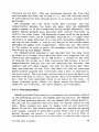
SUMMARY
Abnormal and potentially dangerous fault conditions in the
anesthesia breathing circuit include leaks,
obstructions,
disconnects, incompetent valves and CO2 absorber malfunction.
Because the current alarms of monitoring devices are not specific
enough, there is a need for an intelligent alarms system that can
determine the integrity of the breathing circuit. Three signals
were measured at three different places: CO2 partial pressure at
the Y-piece, airway pressure at the patient side of the
inspiratory valve and airway flow at the patient side of the
expiratory valve. From these measurements features were extracted
for each signal, and the feature changes were analyzed. From
these analysis a rule base was designed, which was implemented
in an expert system by using the SIMPLEXYS expert systems
language. Real time signal analysis and feature extraction were
implemented in a multitasking environment. Initial tests were
performed.
It was found that an implementation of the total system was
possible on an IBM-AT with the multitasking environment MultiDosPlus. The intelligent alarms system was able to distinguish the
following
malfunctions:
inspiratory
valve,
incompetent
incompetent expiratory valve, exhausted CO2 absorber, obstruction
at the Y-piece, obstruction at the inspiratory hose and
obstruction at the expiratory hose. The rule set is currently
being expanded with rules for leaks and disconnects.
InteLligent ALarMs in Anesthesia
i
SAMENVATTING
Abnormale en potentieel gevaarlijke foutencondities in het
beademings circuit dat tijdens anesthesie gebruikt wordt, bestaan
onder meer uit lekken, verstoppingen, losgeraakte verbindingen,
nietwerkende kleppen en een niet goed functionerende CO2
absorber. Orndat de huidige alarmering van de monitors niet
specifiek genoeg is en onvoldoende informatie geeft, is er
behoefte aan een intelligent alarmerings systeem dat kan
uitzoeken wat er mis is in het beademings circuit. V~~r de
implementatie wordt gebruik gemaakt van drie signalen die gemeten
worden op drie verschillende plaatsen: partiele CO2 druk bij het
T-stuk, druk in de inademings gedeelte van het beademings
circuit, gasstroom in het uitademings gedeelte van het beademings
circuit. uit deze metingen werden features gehaald, en de
veranderingen van de features werden geanalizeerd. Uit de
resultaten van deze analyze werd een regelset ontworpen, welke
in een expert systeem ge:implementeerd is m. b. v. de S IMPLEXYS
expert systeem taal. Real time analyze en feature berekening zijn
ge:implementeerd in een multitasking omgeving. Voorlopige tests
zijn uitgevoerd.
Een implementatie van het totale systeem bleek mogelijk te
zijn op een IBM-AT met de multitasking omgeving van MultiDosPlus. Het intelligente alarm systeem kon de volgende fouten
onderscheiden: niet-werkende inademings klep, niet-werkende
uitademings klep, uitgeputte CO 2 absorber, verstopping van het
T-stuk, verstopping van de inademingsbuis en verstopping van de
uitademingsbuis. Op het moment wordt de regelset uitgebreid met
regels voor lekken en onderbrekingen.
Intelligent Alaras in Anesthesia
ii
CONTENTS
page
SUMMARY
SAMENVATTING
i
ii
LIST OF FIGURES
v
LIST OF TABLES
vi
INTRODUCTION .
vii
Chapter 1: An introduction in Anesthesia
1.1 Introduction
1.2 Anesthesia machine . . . .
1.3 Ventilator . . . . . . . .
1.3.1 Ventilator settings
1.4 High pressure part
1.5 Low pressure part . .
1.5.1 Flow settings
1.6 Circle system . . . .
1.7 Scavenging system . .
1
Chapter 2: Signal measurement versus detection
2.1 Introduction
•...•....•
2.2 What do we want to detect • . . . •
2.3 Which signal do we want to measure?
2.3.1 Monitors
2.3.2 Previous work
7
7
7
1
1
3
3
4
4
5
5
6
9
9
9
Chapter 3: Data analysis
3.1 Introduction
3.2 General approach
3.2.1 Phase detection
3.2.2 Parameter calculation
3.2.2.1 Calculating levels
3.2.2.2 Calculating slopes
3.2.3 Parameter validation
3.4 Pressure in the inspiratory limb
3.5 Flow in the expiratory hose
11
Chapter 4: Feature analysis . . . •
4.1 Introduction
....
4.2 Normal curves versus malfunctions
4.3 Detection rules . . . . . .
19
19
20
Chapter 5: An introduction in expert systems
5.1 What is an expert system? .
5.1.1 Knowledge base . . • . . . •
5.1.2 Inference engine . . . . . .
5.2 SIMPLEXYS: an expert system building tool
5.2.1 The SIMPLEXYS rule compiler
5.2.2 A SIMPLEXYS program
5.3 Implementation in SIMPLEXYS . . . .
Intelligent ALarms in Anesthesia
11
11
12
12
12
13
15
16
17
25
28
28
29
29
29
30
30
32
iii
Chapter 6: Program considerations
6.1 Introduction . • . . .
6.1.1 Signal analysis
6.1.2 Feature analysis
6.1.3 Rule evaluation
6.2 MultiDos-Plus . • . . .
6.3 Intertask communications
6.3.1 Information block
6.4 Implementation • • . .
6.4.1 Flow measurement.
33
33
33
34
34
35
35
36
37
38
Chapter 7: Conclusions an Recommendations
7.1 Conclusions . .
7.2 Recommendations
40
40
40
LITERATURE . . . . . • .
42
APPENDIX A: Programming tools
44
APPENDIX B: Manual utility routines
45
APPENDIX C: OMHEDA 5410 VOLUME MONITOR
55
IntelLigent Alaras in Anesthesia
iv
LIST OF FIGURES
page
Figure
Figure
Figure
Figure
Figure
Figure
Figure
Figure
Figure
Figure
Figure
Figure
Figure
Figure
1.1:
1.2:
2.1:
3.1:
3.2:
3.3:
3.4:
4.1:
4.2:
4.3:
4.4:
4.5:
4.6:
5.1:
Block diagram anesthesia system
Circle breathing circuit
Inspiratory valve
Normal CO2 signal
Simple electrical lung model
Normal pressure signal
Normal flow signal
CO2 features
CO2 features
Pressure features
Pressure features
Flow features
Flow features
The building of an expert system
Intelligent Alarms in Anesthesia
1
5
7
15
16
17
18
24
24
24
24
24
24
28
v
LIST OF TABLES
page
Table
Table
Table
Table
I: CO2 signal
II: Pressure signal
III: Flow signal . .
IV: Extracted features
Intelligent Alar.s in Anesthesia
15
17
18
19
vi
INTRODUCTION
This project was done as part of the fulfillment of the
requirements for a M.Sc. degree in Electrical Engineering at the
Eindhoven University of Technology,
Division of Medical
Electrical Engineering, The Netherlands. The research was
performed at the University of Florida, College of Medicine,
Department of Anesthesiology in Gainesville, U.S.A. Funding for
the research was provided by Ohmeda in Madison WI, manufacturer
of anesthesia equipment.
Problem definition
Dur ing surgery, a patient is under anesthesia. This is an
induced state in which the patient is unconscious, insensitive
to pain, and the muscles of the patient are relaxed to the point
where respiration must be supported by external means; an
anesthesia system is used for this support. The risk of
anesthesia is small. It is estimated that between 2 and 10
anesthesia related incidents result in death for every 10,000
anesthetics [ORK86]. A large percentage of these incidents are
due to human error and equipment failure [C0078]. Monitoring
devices are used by the anesthesiologist for early detection of
unwanted situations. Most monitors are equipped with alarms that
generate a sound when a user settable threshold has been
exceeded. At some critical moments, many monitors can and will
sound an alarm and the clinician is overwhelmed with an abundance
of tones; it is the clinician's task to analyze the multitude of
unspecific alarms and reach a conclusion about what exactly is
going on.
An unwanted situation can be the result of either an equipment
malfunction or a patient problem.
The first thing the
anesthesiologist does is to check the equipment. If this appears
to work well, the anesthesiologist checks the patient. It is our
goal to develop a system that helps the anesthesiologist to reach
a conclusion about the nature of the alarm situation. This stUdy
is a start; it focusses on the integrity of the anesthesia
system.
If we let a computer monitor the anesthesia system (in the
Intelligent Alarlls in Anesthesia
vii
same way as the anesthesiologist does) and if we give the
computer the same knowledge the anesthesiologist uses to reach
a conclusion about the source of the alarm, such an aid could be
developed. This report describes how a clinician monitors the
anesthesia system and how to implement this knowledge in a
computer so that an intelligent (alarms) system can be developed,
that aids the clinician to reach a conclusion about the possible
problem more rapidly.
Problem approach
For now, we limit our intelligent alarms system to the
integrity of the breathing system of the anesthesia system (for
a description of the anesthesia system and the breathing system
see chapter 1).
A definition of what can go wrong with the breathing system
has to be made. It has to be determined which signals have to be
measured and where in the system they have to be measured. A
continuous analysis of these measurements has to be made to
determine whether a malfunction exists and if so, what exactly.
Symbolic data will be derived from the signals and these will be
given to an expert system containing the domain specific
knowledge, which will reach a conclusion about the integrity of
the breathing circuit. The following is a list of tasks that
needed to be done to implement an intelligent alarms system.
These tasks will be described in this report.
- Define the malfunctions that we want to detect.
Make a comprehensive list of all dangerous malfunctions
by interviewing anesthesiologists and studying the used
anesthesia system (chapter 2).
- Define which signals must be measured to detect these
malfunctions, and where in the system they must be measured.
Find out which monitors are normally used and which
monitors are available. Place the sensors so that an
optimal malfunction detection can take place (chapter 2).
- Record the signals that result after wilful introduction of
Intelligent AlarBs in Anesthesia
viii
the earlier defined malfunctions (with a simulated patient).
Sample the signals so they can be processed by a computer,
and plot them.
- Analyze the recorded data, define and extract their important
features.
Define important features for every signal, calculate the
features (chapter 3).
- Analyze the features, define how these features change for
every malfunction.
Extract detection rules for every malfunction (chapter
4) •
- Incorporate the derived knowledge in an expert system.
Make an expert system that reaches a conclusion about the
integrity of the system, using a set of detection rules
(chapter 5).
A real time implementation of the intelligent alarms system
has been made; it is described in chapter 6.
IntelLigent ALaras in Anesthesia
ix
Chapter 1: An introduction in Anesthesia
1.1 Introduction
Anesthesia is a state of unconsciousness, analgesia (the
blocking of pain), and relaxation of the muscles. This state is
needed during surgery to help the surgeon perform the operation.
The anesthetic state is induced by an anesthesiologist, usually
a physician trained to administer anesthetics.
The most common method in the U.S.A. to obtain anesthesia is
inhalation of one or more anesthetic gases. Because all the
patient's muscles are relaxed, he can not breathe himself. The
anesthetic mixture, a mixture of anesthetic gas(es) and oxygen,
prepared by an anesthesia machine and supplied by a ventilator,
is forced into the patient via a breathing circuit and through
a tube brought into the trachea (endotracheal tube).
1.2 Anesthesia machine
There are several different anesthesia machines in use. I will
concentrate on the Ohmeda Modulus II Anesthesia System, which is
used in Shands hospital in Gainesville.
The Modulus II is most often used with a circle breathing
system. In a circle system the gases, exhaled by the patient, are
reused. A great advantage of this method is that the quantity of
anesthetic agent that is needed decreases, because the exhaled
(unused) fraction of the agent is reused. In the patient'S lungs
CO2 is replaced by oxygen, so the patient exhales CO2 that has to
be removed from the breathing circuit; this is done by the CO2
absorber.
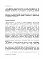
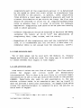
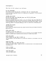
The following 5 parts can be identified in the inhalation
anesthesia system:
- High pressure system
connections to the wall outlet or gas tanks.
Intelligent ALarms in Anesthesia
1
circle
systeIIl
••
Ventilalor/
Scavenging
Syst.eIll
1.1 :
Block
anesthe
system
composed by J.S. Gravenstein M.D.
- Low pressure system
flow control valves with
administer anesthetics.
flow
meters,
vaporizer
to
- Scavenging system
excess gas outlet.
- Ventilator system
ventilator, hand bag.
- Circle breathing system
CO 2
absorber,
hoses
to
connect
to
the
endotracheal tube, unidirectional valves.
patient,
The high pressure and low pressure systems together are called
the anesthesia machine.
Intelligent Alar.s in Anesthesia
2
1 . 3 Ventilator
The ventilator is the driving source of the anesthesia system.
This device forces the gas mixture via the breathing circuit into
the patient. In case of an emergency, a hand bag in the system
can be used to manually ventilate the patient.
1.3.1 Ventilator settings
The ventilator can be set to accommodate patients of different
age, weight, physical condition and the type of operation.
Typical controls on an anesthesia ventilator are:
- Minute volume dial
This dial is used to set the number of liters per minute
of gas delivered to the lung.
- Rate dial
This dial is used to set the respiratory rate (number of
breaths per minute).
- I:E ratio dial
This dial is used to set the ratio of inspiration time
to expiration time.
Some basic principles to set these values are:
- Minute volume = Tidal volume * Respiratory rate.
At normal respiratory rates, the tidal volume shoUld be lOIS ml/kg body weight. This is the inspired tidal volume; it
is delivered to the patient during the period called the
inspiration time. There is also an expired tidal volume. It
is different from the inspired tidal volume because the
expired gas is at a different pressure, at a different
temperature, has a different composition, and because the
respiratory quotient is not exactly equal to one.
- Inspiratory Flow = Minute volume * (1 + Ell).
The inspiratory flow (which is constant, due to the mechanics
of the system) must deliver the gas volume during the
InteLligent Alarms in Anesthesia
3
inspiratory part of the respiratory period; it is determined
by the speed at which the tidal volume is transferred from
the bellows to the patient. In general, lower inspiratory
flows produce a lower peak inspiratory pressure and lead to
a better distribution of gas within the lungs. The flow rate
should be adjusted to allow for an inspiratory/expiratG'rY
ratio no greater than 1, in order to provide for adequate
expiration. Inspiratory flow rates of 40-50 L/min are usually
used.in adult patients.
- Alveolar respiration should be adjusted to maintain the PaC02
(alveolar CO2 level) at 30-35 torr* (by adjustments of
respiratory rate, tidal volume, and I:E ratio).
- Regardless of the respiratory rate and the inspiratory flow
rate, it is recommended that the I:E ratio is more than 1:1;
otherwise there is not enough time for exhalation. [LIC74]
1.4 High pressure part
Two or more gases can be used with the Modulus II. Usually
Oxygen and Nitrous oxide are used. For every gas it is possible
to choose between wall supply or tank supply.
1.5 Low pressure part
Flow control valves set the flow of every gas. The flow control
are mechanically
oxide
oxygen
and
nitrous
valves
for
interconnected. This 1S done to be sure there is a minimum oxygen
concentration of 25% in the gas mixture delivered to the patient
[OHMS3]. Vaporizers are used to add anesthetics to the gas
mixture (nitrous oxide is an anesthetic gas, but by itself it
does not provide a sufficient anesthesia). An oxygen flush valve
allows the anesthesiologist to temporarily give the patient an
extra dose of oxygen.
*1
.
torr 15 aLMOst equal to 1 MMHg. 1 kPa is equal to 7.5 .-Kg.
Intelligent Alar.s in Anesthesia
4
1.5.1 Flow settings
Not only the ventilator dials need to be set, also the fresh
gas flow has to be set. Usually two gases are used: 02 and N20.
So the total gas flow and the fraction of 02 (Fi02) can be set.
The Fi02 should be such that the concentration 02 in the
mixture is at least 21%. The Fi02 should be as low as possible to
avoid the toxicity of high concentrations of oxygen. For patients
with normal lungs 40% 02 is usually adequate, but during short
periods 100% can be necessary.
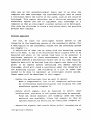
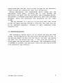
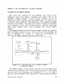
1.6 Circle system
The circle system consists of two parts: the inspiratory limb
and the expiratory limb. When the ventilator cycle starts, the
inspiratory valve opens and the expiratory valve closes. Gas
1""':"'---,
i nsp ira tory
valve
inspirator!,!
fresh
hose
9as
••
.,
C02
•••
absorber
!'-:,...".---;."'.=-=•. .",-"---;.:-' •••I,--,c---'.=-ven t i l a t or
expiratory
valve
Figure 1.2: Circle breathing circuit
Intelligent Alarms in Anesthesia
5
(both fresh gas and gas recirculated through the CO2 absorber)
flows through the inspiratory hose into the patient.
During expiration, the inspiratory valve closes and the
expiratory valve opens, allowing gas to flow through the
expiratory hose back into the ventilator and scavenging system.
The patient's inflated lungs empty passively, much like a balloon
deflates, after the ventilator has delivered the set tidal
volume.
The CO2 absorber is a canister filled with soda lime, which
scrubs the gases passing through it from CO2 , The soda lime has
to be replaced regularly, because it gets exhausted after
extensive use.
1.7 Scavenging system
The scavenging system exists of an excess gas bag and some
valves. During expiration the ventilator bellows gets filled. If
the bellows overfills and hits the top of its case, the excess
gas goes into the excess gas bag. If even more gas arrives, a
valve opens and the gas exits the system. The scavenging system
is needed to prevent the operation room from getting polluted
with anesthetic gas mixtures.
Intelligent Alarms in Anesthesia
6
Chapter 2: Signal measurement versus detection
2.1 Introduction
Our goal is to derive a conclusion about the integrity of the
breathing circuit from information present in the signals
measured in or near the breathing circuit. Many things can go
wrong with the breathing circuit of an anesthesia machine. With
the current technology, it is difficult to conclude what exactly
goes wrong, because several different monitors may give partially
overlapping and quite unspecific alarms.
Our first task is to find out which malfunctions should be
detected and alarmed on. Secondly, we have to determine which
signals are to be measured in the breathing circuit and where we
should measure these signals in order to best detect these
malfunctions.
2.2 What do we want to detect
The circle breathing circuit exists of disposable plastic
hoses, unidirectional valves, and a COz absorber. Because the
hoses have to be easily replaceable, leaks and disconnects can
occur. If the hoses kink, an obstruction may result. As indicated
in 1.6, the soda lime of the COz absorber can get exhausted,
resulting in inadequate ventilation by QQz rebreathing.
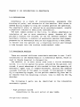
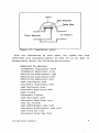
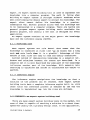
The uni-directional valves consists of a disc that elevates
when the pressure on one side higher is than the pressure on the
other side. The disc's movement is limited by a retainer. The
disc is made of flexible plastic, and when it becomes moist
(humidity of expired gas is high) it is possible that the ~
gets stuck in the open position. The dome is transparent and
removable, so a stuck valve can be confirmed and repaired.
IntelLigent Alarms in Anesthesia
7
Disc Retainer
Valve Dille
FTOTn AbsOTbeT
To Patient
Figure 2.1: Inspiratory valve
From the information we have about the system and from
interviews with anesthesiologists we have set as our goal to
automatically detect the following malfunctions:
Exhausted CO2 absorber
Incompetent Inspiratory valve
Incompetent Expiratory valve
Obstruction Endotracheal tube
Obstruction Inspiratory hose
Obstruction Expiratory hose
Leak Inspiratory hose
Disconnect Inspiratory hose
Leak Expiratory hose
Disconnect Expiratory hose
Leak V-piece
Disconnect v-piece
Leak Ventilator hose
Disconnect ventilator hose
Leak CO2 canister
Leak Endotracheal tube cuff
Disconnect Endotracheal tube cuff
Leak Fresh Gas Flow
Disconnect Fresh Gas Flow
Intelligent Alarms in Anesthesia
8
2.3 Which signal do we want to measure?
In order to detect malfunctions, several signals will have to
be measured from the circle system. If possible, we would like
to use the standard set of measurements.
2.3.1 Monitors
We want to detect malfunctions in a system where gases flOW,
and where CO2 is added and extracted. The logical thing to do is
to measure CO2 , pressure and flow. In anesthesia monitoring CO2
and pressure are usually monitored, but flow monitoring is not
cornmon. It is much more cornmon to measure expired volume, the
integral of the (expiratory) flow over the expiratory period.
CO2 , pressure and volume monitors are now standard and widely
available. In the Ohmeda Modulus II the Ohmeda 5200 CO2 monitor,
the Ohmeda 5500 airway pressure monitor and the 5410 volume
moni tor are used. Other signals, like O2 percentage, oxygen
saturation, blood pressure and anesthetic agent percentage, are
usually measured by additional monitors. In a system where flow
and CO 2 monitoring are the major features, we choose to use CO2 ,
pressure and flow signals.
2.3.2 PreVious work
Previous work has been done in this field by Rob Bastings
[BAS87) and Jan van der Aa [AA87). They measured CO2 , pressure
and flow signals at the Y-piece. As result of these measurement
they could detect 5 clusters of malfunctions:
cluster 1:
Endotracheal tube leak
Leak in expiratory hose
Ventilator tube leak
cluster 2:
Leak in inspiratory hose
Partial disconnect of the fresh gas flow
Intelligent Alar., in Anesthesia
9
cluster 3:
Incompetent inspiratory valve
cluster 4:
Incompetent expiratory valve
Exhausted CO2 absorber
cluster 5:
Increased airway resistance (obstructions)
It was not possible to distinguish between malfunctions within
a cluster. The advantage of an integrated sensor at the Y-piece,
that they used, is that there is only one sensor that has to be
placed. The disadvantage is that malfunctions far from the
sensors are hard to pick up and because all sensors are located
in one place, the detection is not optimal. Ideally we would like
to have a sensor in every limb of our system, but this would
require a very complicated build-up of the system, with a higher
possibility of errors, and a higher possibility of sensor
malfunction.
Traditionally, in the Modulus II with circle breathing system,
the CO2 is measured at the Y-piece, pressure in the inspiratory
hose and flow in the expiratory hose. This is the setup we choose
to use. It gives us the advantage of using standard equipment and
thus easier testing, because we can setup our system with a
standard anesthesia system.
Intelligent Alarms in Anesthesi6
10
Chapter 3: Data analysis
3.1 Introduction
If a computer program is to derive conclusions from analog
signal wave forms, samples of the wave forms are needed as input
to the computer. On practical grounds, we conclude that for our
signals a sample rate of 20 Hz is enough to extract the important
information from these samples.
3.2 General
a~~roach
First we have to determine the kind of information the signals
contain. A set of features of each signal has to be defined, so
that the feature set resembles the signal's clinically useful
information closely.
We limit our signals to (almost) periodic signals, that can
be described by a sequence of segments with the following
attributes:
- horizontal
- slope
- exponential curve
{ HORIZ }
{ SLOPE }
{ EXPON }
Each attribute has parameters associated with it. HORIZ has
start-time, end-time, level. SLOPE has start-time, end-time,
start.-value, slope. EXPON has start-time, end-time, timeconstant.
A-priori information about the signal must be available to
know in which phase (or segment) the signal is (every phase has
an attribute associated with it).
So a signal analysis routine consists of the following parts:
- phase detection
Determines in which phase the signal is.
- parameter calculation
Calculates the parameters for each phase.
Intelligent Alarms in Anesthesia
11
- parameter validation
Determines if the parameter can be calculated.
3.2.1 Phase detection
Phase detection is more difficult than it seems at first. with
well-defined, noise-free signals, it would not be difficult, but
data from patients is corrupted with noise and artifacts. To
determine the phase, we can use both the signal and the
derivative. Limits have to be set to determine the phase. This
work was done by Rob Bastings [BAS87]. The next quote from his
report describes his method of phase detection. "The samples are
filtered with a digital low pass filter (moving average filter,
HvO) to obtain a mean value. A positive and negative amplitude
can be obtained by filtering the samples above and below the mean
value. The low and high thresholds are defined as the sum of the
mean value and 50% of the positive and negative amplitude
respectively. ( ..• ) This method decreases the number of false
level detections.
An estimation of the derivative is used to determine if a high
or low level is reached." ([BAS87] p. 24,25)
3.2.2 Parameter calculation
The parameters that have to be calculated are slopes (of a
curve segment), levels (of a horizontal line) and time constants
(of a curve segment). The developed signal-processing routines
are robust with regard to noise, i.e. noisy data still yield a
good enough result. They are ~ artifact-resistant; artifacts
must be detected (and removed) by another method.
3.2.2.1 Calculating leVels
In the calculation of the level of what we call 'a horizontal
line', (in practice this line will be noisy, and it will not
always be strictly horizontal either), two levels can be
important: the maximum and the minimum. In some cases the maximum
is important, in other cases the minimum.
In the ideal
lntell igent ALarD in Anesthesia
12
'horizontal line', the maximum and the minimum are of course the
same.
Maximum and minimum can be calculated with the following
algorithm:
if
if
sample , max
sample ( min
max
min
=
=
sample;
sample;
A proper initialization of max and min is needed (eg. min
highest possible minimum if the search is for a minimum).
,=
3.2.2.2 Calculating slopes
Since our signal is noisy, the slopes must be calculated in a
way such that noisy signal values yield an accurate value for the
slope.
Assume that our data points are modelled by the line
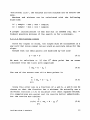
y = ax + b
(3.1)
We want to calculate a. If the kth data point has an error
(distance from the line) with magnitude
(3.2)
The sum of the errors over all m data points is
m
(3.3)
1:
k=1
Since this error sum is a function of a and b, a and b can be
chosen so that the function has a minimum. We actually use a
different function (3.4) to minimize (the least squares method;
its computations are easier and its results better understood),
but the results are similar.
m
(a,b)
=1: ( aX k
+ b -
Yk
)
2
(3.4)
k=1
Intelligent Alaras in Anesthesia
13
The conditions to minimize this are:
=
0,
=
o.
(3.5)
Applying this results in:
m
L
k=l
2 ( aX k + b - Yk ) x k = 0
(3.6a)
2 ( aX k + b - Yk ) = 0
(3.6b)
m
L
k=l
Taking in account that t.1 1 = m, the solution for a and b is:
a = lId
(
m
m
m
m L xkYk - L x k L Yk
k=l
k=l k=l
= lId
(
m
m
m L x 2 L XkYk
k=l k k=l
b
m
(3.7a)
)
m
- L Xk L Yk
k=l
(3.7b)
k=l
where
(3.8)
[CHE8S)
We use equations (3.7a) and (3.8) to calculate the slope of a
curve.
3.2.2.3 Calculation time constants
For an exponential curve a similar calculation is used to
calculate the time constant T, were we take the natural logarithm
of the samples, minus the offset of the exponential curve.
Y = exp(-Tx) + Yo
In(y - Yo)
=
Intelligent Alar.s in Anesthesia
-Tx
(3.9)
(3.10)
14
y'
=
-Tx
(3.11)
Our signals are assumed to have only the attributes described
above. In order to represent the signal by segments having only
these attributes, we must have a-priori information about the
signals to be able to describe the signal as a sequence of
segments (phases). We have to determine which attribute a signal
has in which segment, and hence which features need to be
calculated when.
3.2.3 Parameter validation
Parameter validation is done for EXPON and SLOPE. In our
algorithms, if less than ten samples are available for slope
calculation, the feature value is not valid (the calculated slope
will not be reliable enough). All the other features are always
calculated, because at this stage the intelligence to determine
if a feature is valid or not is not available. This will be
available in a later stage (an expert system).
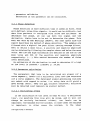
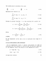
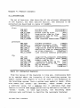
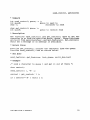
3.3 CO2 siQ"nal
The CO2 signal, measured at the V-piece, consists of 2 major
parts: 1) the plateau during expiration, 2) the zero plateau
during inspiration.
status
attribute
feature
1
HORIZ
SLOPE
HORIZ
SLOPE
Inspired CO2 level
Up slope
Expired CO2 level
Down slope
2
3
4
Table I: CO2 signal
Intelligent ALarMs in Anesthesia
15
InnH91
88
G8
411
3
i~
/
2111
.4
8~__~__~'~1~____~~,__~______~____________
8
:I
G
9
t2
Figure 3.1: Normal CO2 signal
tS
to
During inspiration, gas (fresh gas and gas through the CO2
absorber) is forced into the patient. This gas normally does n
ot contain any CO2 . During expiration the CO2 level will increase
until it reaches a level that is approximately equal to the
alveolar CO2 level.
The CO2 signal at the Y-piece is described in table I and in
figure 3.1.
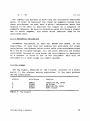
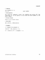
3.4 Pressure in the inspiratory limb
A breathing circuit with a lung can be modeled by a resistorcapacitance circuit.
Figure 3.2: Simple electrical lung model
The flow is modelled with the current
vOltage v.
I,
the pressure with
Equationo~
(3.12)
Intelligent Alar.s in Anesthesia
16
I = (V - Vc)/R
(3.13)
During inspiration, the gas is forced into the patient with a
constant flow (I=constant). So Vc has a linear increase (from eq.
3.12) and V also has a linear increase because of eq. (3.13).
During expiration the capacitor (representing mostly compliance
of the lungs) is discharged, resulting in an exponential
decrease.
status
attribute
feature
1
SLOPE
EXPON
HORIZ
up slope, maximum
time constant
minimum
2
3
Table II: Pressure signal
IcMH20J
16
12
8
4
/-
f'
1/
'.2
;
\ ....
.
/
:
0
,/
3
;
..
/-
r
"'--
;
i
:
',-
B~--~--~----~--~----~--~--------(secJ
18
B
3
6
12
15
9
Figure 3.3: Normal pressure signal
The pressure signal in the inspiratory hose is described in
table II and in figure 3.3.
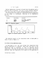
3.5 Flow in the expiratory hose
As described in 3.4, the flow through the
during inspiration is constant. Since only
expiratory limb is measured, no flow is
inspiration. Only when the expiratory valve is
measured. When the expiratory valve opens at
Intelligent Alarms in Anesthesia
inspiratory hose
the flow in the
measured during
open, flow can be
the beginning of
17
expiration, there is a steep increase in the flow. As described
in 3.4, the capacitor discharges and hence the flow decreases
exponentially.
.\
22
7
-8
.
.,
IPl1/s)
\1
"-
''---
....'.
:3
2
\
',-
'\........
~.
-23
-38
a
3
S
9
i2
i!:
i9
lsecl
Figure 3_4: Normal flow signal
The expiratory flow signal is described in table III and in
figure 3.4.
status
attribute
feature
1
2
3
EXPON
HORIZ
time constant
minimum
maximum
Table III: Flow signal
Intelligent Alarms in Anesthesia
18
Chapter 4: Feature analysis
4.1 Introduction
The set of features, that describe all the relevant information
in the signals, has been defined earlier. The features to be
extracted are described in table IV [BAS87).
flow:
FLW MIN
FLW MAX
FLW B TIME
FLW- INS- T
FLW_EXP_T
FLW_EX_VOL
FLW_T_CONST
minimum flow.
[Liters/min)
maximum flow.
[Liters/min)
breath time by flow.
[sec)
inspiration time by flow.
[sec)
expiration time by flow.
[sec)
expired volume.
[Liters)
time constant downstroke fl~wec)
pressure:
PRS MIN
PRS MAX
PRS B TIME
PRS_INS_T
PRS- EXP- T
PRS SLOPE
PRS T CONST
minimum pressure.
[cmH20)
maximum pressure (PIP).
[cmH20)
breath time by pressure.
[sec)
inspiration time by pressur~sec)
expiration time by pressure~sec)
up slope pressure.
[cmH2 0/sec)
time constant downstr press~sec)
C02 INS
C02-EXP
C02 B TIME
C02 DO TIME
C02-EXP T
c02=up3TR
C02 DO STR
inspired CO2 pressure level~mmHg)
expired CO2 pressure level. [mmHg)
breath time by CO2 ,
[sec)
'inspiration time' by CO2 , [sec)
expiration time by CO2 ,
[sec)
CO2 up stroke.
[mmHg/sec)
CO2 down stroke.
[mmHg/sec)
Table IV: Extracted features
From the values of the features in this set, conclusions have
to be reached about the integrity of the breathing system. An
expert system (see chapter 5) will be used in the diagnosis of
the breathing system. Such a system uses symbolic input, often
with names like 'normal' and 'abnormal', where 'normal' is not
a numerical value, but a logical onei it indicates that some
feature is within some range operationally defined to include all
'normal' values. In this application, the following three
statuses were sufficient to describe the necessary features:
lntelligent
Ata~ms
in Anesthesia
19
UC Unchanged
The feature value is within a band around a normal value*.
UP Up
The feature value is higher than the upper threshold.
DN Down
The feature value is lower than the lower threshold.
The thresholds were defined as 20% higher and 20% lower than
the normal value or 'baseline'. This gives a 40% 'normality
band'. This relative value (the band width is expressed as a
percentage) gives problems if 'normal' is close to zero.
Therefore a band width of 2 (-1 to +1) was taken if the feature's
value was smaller than 5. This is useful for the CO2 and flow
signals, because their minimum is zero.
The values used here are arbitrary values. More research needs
to be done about how to derive 'baselines' and how to set the
detection bands, in order to get optimum detection. This research
is planned for the future.
4.2 Normal curves versus malfunctions
In order to know how the signals (or rather the features)
behave in the case of a malfunction, we measured the three
signals with the set of malfunctions of 2.2, generated by the
anesthesia simulator (a modified anesthesia system that can
introduce a number of malfunctions [GOOB7]).
The data from these measurements were analyzed, and the
features were extracted with the techniques described in chapter
3. The feature values were plotted in graphs in order to compare
the time course of the values, that result from any single
malfunction, with the normal values.
*Nor.al value ;s the value of a feature when there are no malfunctions or disturbances. A feature
value that didn't change over a certain period of tiMe can be called a normal value,
anesthesiologist didn't find it necessary to change somethinQ.
Intelligent Alar.s in Anesthesia
since the
20
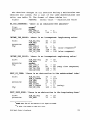
The absolute changes of all features during a malfunction was
obtained and listed. For a list of the used abbreviations and
units, see table IV. The format of these tables is:
signal
FEATURE
normal value -, malfunction value
BS_C02_ABSORBER: 'there is an exhausted C02 absorber'
flow:
pressure:
CO2 :
normal *
normal
C02_INS_P
C02 DO STR
o
-, 5
118 -, 111
INCOMP_INS_VALVE: 'there is an incompetent inspiratory valve'
flow:
pressure:
CO2 :
FLW EX VOL
FLW MAX
DQrIDal
CO2 - INS P
C02 EXP-P
C02_DO_STR
C02 UP STR
36
32
0
48
118
100
-,
-,
-,
-,
-,
-,
15
16
5
60
(slow response) **
20
120 (slow response)
INCOMP_EXP_VALVE: 'there is an incompetent expiratory valve'
flow:
pressure:
CO2 :
FLW_EXP_VOL
FLW MIN
DQl:Jllal
CO2 - INS P
CO2 - EXP P
CO2 - DO STR
CO2 - UP STR
36
0
-,
-,
20
-11
0
50
118
100
-,
18
60 (very slow response)
90
70
-,
-,
-,
OBST_ET_TUBE: 'there is an obstruction in the endotracheal tube'
flow:
pressure:
CO2 :
FLW EX VOL
FLW T CONST
FLW MAX
PRS MAX
PRS - SLOPE
PRS _T_CONST
CO2 - UP STR
36
1
32
13
6
1
100
-,
-,
-,
-,
-,
-,
-,
33
2.5
15
28
13
3 (noisy)
65
OBST_INSP_HOSE: 'there is an obstruction in the inspiratory hose'
flow:
pressure:
FLW EX VOL
PRS MAX
*D2tmA1 means that all the features of
** It takes a few breaths to reach this
Intelligent Alarms in Anesthesia
36
-, 33
13
-, 29
this signal are normal.
value.
21
PRS SLOPE
noriiial
6
-, 13
OBST_EXP_HOSE: 'there is an obstruction in the expiratory hose'
flow:
pressure:
CO2 :
FLW_T_CONST
FLW MAX
PRS T CONST
DQriiial
1
32
1
-,
-,
-,
2.5
15
1.7
DISC Y PIECE: 'there is a disconnect at the Y-piece'
flow:
pressure:
CO2
.
FLW EX_VOL
FLW- MAX
signal
flat
signal flat
36
32
-, 7
-, 20
DISC_INSP_HOSE: 'there is a disconnect of the inspiratory hose'
flow:
pressure:
CO2
FLW_EX_VOL
FLW MAX
signal flat
signal flat
36
32
-, 8
-, 20
DISC_EXP_HOSE: 'there is a disconnect of the expiratory hose'
flow:
pressure:
CO2 :
FLW_EX_VOL
FLW MAX
signal flat
signal flat
36
32
-, 7
-, 20
DISC FGF: 'there is a disconnect of the Fresh Gas Flow'
flow:
pressure:
CO2 :
FLW EX VOL
FLW_MAX
PRS_MAX
PRS T CONST
CO2 _DO_STR
CO2 UP STR
36
32
13
1
118
100
-,
-,
20
22
-,
0.5
180
80
-,
-,
-,
4
DISC_VENT_HOSE: 'there is a disconnect of the ventilator hose'
flow:
pressure:
CO2 :
*signal
signal flat
signal flat
signal flat
flat lteons that the signals have so little variation that no breath detection could be
perforited.
Intelligent Alarms in Anesthesia
22
Leaks of three different sizes were measured. Leaks of sizes
1.5rnrn, 2rnrn and 3rnrn (diameter) were introduced. The format of the
following result table is:
signal
FEATURE
normal value -, 1.5rnrn, 2rnrn, 3rnrn leaks
LEAK_Y_PIECE:
flow:
pressure:
CO2 :
FLW_EX_VOL
FLW_MAX
PRS_MAX
PRS SLOPE
PRS T CONST
C02 DO STR
C02::::DO::::TIME
28 -, 21, 18, 15
38 -, 32, 28, 23
18 -, 16, 15, 14
-, 4.5, 4, 3
6
0.3 -> 1, 3, 6
100 -> 30, 40, 50
1.5 -, 3.5, 4.5, 4.5
FLW EX VOL
FLW MAX
PRS T CONST
PRS_MIN
PRS_MAX
CO2 DO STR
28 -,
37 -,
0.3 -,
-,
7
18 -,
100 ->
FLW_EX_VOL
FLW MAX
PRS MAX
PRS T CONST
PRS- SLOPE
CO2 DO STR
CO2 - DO TIME
28
37
18
1.2
6
100
1.8
-,
-,
-,
-,
-,
-,
-,
21, 19, 15
32, 28, 25
16, 15, 14
2, 4, 6
6, 6, 3.5
50, '"50, 60
1. 8, 1. 8, 4.2
FLW_MAX
PRS EX VOL
PRS MAX
PRS- SLOPE
PRS T CONST
CO2 - DO TIME
CO2 DO STR
38
28
18
6
0.3
1.5
100
-,
33, 32, 30
27, 22, 21
16, 15, 13
5, 4, 3
2, 4, ?
1. 5, 1.5, 3.5
100, 100, 30
LEAK INSP_HOSE:
flow:
pressure:
CO2 :
-
21, 19,
32, 29,
2, 4, 6
7, 7, 6
16, 15,
70, 70,
15
25
13
50
LEAK_EXP_HOSE:
flow:
pressure:
CO2 :
-
LEAK_VENT_HOSE:
flow:
pressure:
CO2 :
-
-,
-,
-,
-,
-,
-,
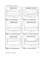
Examples of the graphs are given in figures 4.1 to 4.6. The
feature values during a malfunction have to be compared with the
values in the normal situation (right and left picture). The
graphs give a good impression of the stability of the features
Intelligent Alarms in Anesthesia
23
in the normal situation.
Normal curves
Incompetent Insp. valve
'o,--------------------------------,
30
."
'SO
"
"
'0
"
",
ls~,:-~.=,~,~,~-,=,~,=o~--:c,,~."'c::-~~,,~,~,~-:,~,=,,~-:,~,~,,:--'o
.,
A
"
A
o
0
10.00
233{) 3785
61.10
114 M
time
-
Ic02
-+- Eco2
-&- UPstr
111115
10(,00 111.80 137.10
~
UPSI'
---b-
DOSlr
C02 le81u, ••
Figure 4.2: CO2 features
Figure 4.1: CO2 features
Incomp. Insp. valve
Normal curves
'0,-------------------------------,
30
"
'"
- t
- ,-
1-
+ - 1--+--+--- ...... -
\-
•
,
_/
-l---
'"
I
If
,
I
,
I
!-
,
t
1- I
1-+- +-1-1
I-I
"!IS lt56 18 co:"'. 20:l1.1Xl38.6r...S 2!>51 Q!i58
0
~OO5 2.~11
gO 78 5586.2001 gO
.
,
'"
time
23.00
:II! 35
(fj,70
Figure 4.3: Pressure features
1\:1.10
16.• 0
0
89_!!1:> 100 00 "1135 13"1,05
time
-+- rna_
p'~.u'e
'-,
,
~~--"~ -.;._-~{t--4~_'j-~-
o/r~~¥
o
o _S
-+- Eco2
-lc02
-.!r- 0081'
CO2 ! ••!u •••
,
n.8S
time
-+-
slope
-b- Teons!
r...,u,.. ~
Flgure 4.4: Pressure features
Incomp. Insp valve
Normal curves
15 - - - - - - - - - - - - - - - - - - - - - . -
.0
'0
30
"
"
." L~_:::"::_'_::::::::~_:::c::_~::':_~_::::':::_-~_=_c=--'o
1'115
111.'6
3280
_510
5Q
"~I
72.76
8!1.10
-15 :.-......-L--L..-.1-I~_'--_~~---'
~fjO
IIrne
time
-
min
-+- ma~
-b- ex VOl
-R--- TconSI
Figure 4.5: Flow features
Intelligent AlarMs in Anesthesia
0
\125 lG.M 431105120105583.85911011060130601.380 16715
-
mLn
·i -
m8~
-6-- 6, ~
--11-- TeOns!
Figure 4.6: Flow features
24
4.3 Detection rules
From the measurements described in the previous paragraph, the
attributes YD, ~ or unchanged can be added to each feature in
case of a malfunction. A description of every malfunction can be
made in the form of rules, that describe the status of the
feature set.
The detection rules were derived from the
differences between the values of the normal and the disturbed
features. A straight forward translation of the observations for
rule BS_C02_ABSORBER would be:
FLOW normal
and
PRESSURE normal
and
and
Now, for all rules, we take the following three steps:
1.
delete all features that are normal; normal is the
default. In this example, this gives the following rule:
2.
delete features that are superfluous, especially if they
are unreliable or noisy. In this example, there are none
of those.
3.
Add enough features to make the rule unique, i.e. prevent
the rule from being true if other problems arise. In this
example, C02_INS_up does occur with other problems, ego
INCOMP_INS VALVE and INCOMP_EXP_VALVE (see the list
above). This step is the most difficult; it requires a
thorough (expert level) understanding of the problem. This
step may reintroduce features that are normal or features
that are llQt up or llQt down. In the example, the following
rule is obtained:
After these steps, no two rules should be equivalent, nor should
any rule be subsumed under another rule (a SIMPLEXYS knowledge
acquisition tool to automatically perform these tests is under
IntelLigent ALarms in Anesthesia
25
development).
The list of all rules is as follows:
BS- C02 - ABSORBER:
C02_INS_up and FLW_EX_VOL_unchanged and not FLW_MIN_down
The rule uses inspired CO2 because the
signaLs are norDBL.
C~
is not scrubbed out by the CO2 absorber. The flow and pressure
INCOMP_INS_VALVE:
FLW_EX_VOL_down and FLW_MAX_down and C02_DO_STR_down
and not FLW_MIN_down
Expi red flow and MaXillU1l flow are down because in thi s case expi rat ion takes place through both the
expiratory hose ADd the inspiratory hose. The CO downstroke is prolonged, because during the first part
2
of the inspiration the gas, that is already in the inspiratory hose, passes the CO2 monitor. This gas
contains CO2, because it is the previous exhaled gas. There is no reverse flow in the expiratory hose.
INCOMP_EXP_VALVE:
FLW- MIN- down
There is reverse flow through the expiratory hose, because inspiration takes place through the inspiratory
ADd expiratory hose.
OBST- INSP- HOSE:
The slope of the pressure is up, because the resistance of the inspiratory circuit has changed. The pressure
DaXiMUM is up, because there is a pressure build-up caused by an increased airway pressure.
OBST EXP HOSE:
- FLW_T_CONST_up and PRS_T_CONST_Up
The time constants of flow and pressure are up, because the resistance of the expiratory circuit has
changed.
OBST ET TUBE:
OBST- INSP- HOSE and OBST- EXP- HOSE
According to the feature changes, it appears that there is an obstruction both in the inspiratory hose and
the expiratory hose.
DISC Y PIECE:
DISC- PATIENT- HOSE
DISC- EXP- HOSE:
DISC- PATIENT- HOSE
Intelligent Alarms in Anesthesia
26
DISC_INS_HOSE:
DISC_PATIENT_HOSE
DISC_PATIENT_HOSE:
FLW_EX_VOL_down and FLW_MAX_down and PRS_flat and C02_flat
There is no breath detection on the pressure and CO signals. The expiratory flow is down. When the
2
inspiratory hose is disconnected, flow will only be detected if the disconnect occurs at the absorber side
of the sensor.
DISC_FGF:
FLW EX VOL_down
PRS_T_CONST_down
and
and
and
Less gas, and at a lower pressure, will flow into the system if the fresh gas hose is disconnected.
DISC_VENT_HOSE:
GENERAL_FAILURE
There is no breath detection at all, because the driving force failed. There is no gas flow in the syste..
GENERAL_FAILURE:
C02_flat and FLW flat and PRS_flat
The leak rules are currently under development. Proposed rules
are given below:
LEAK PATTERN:
FLW EX VOL down
and
FLW MAX down
PRS=T_CONST_Up and C02_DO_STR_down
and
PRS- MAX- down
and
LEAK Y PIECE:
LEAK=PATTERN and C02_DO_TIME_up and PRS_SLOPE_down
LEAK INS HOSE:
LEAK=PATTERN and PRS_MIN_down
LEAK_EXP_HOSE: {== LEAK_Y_PIECE }
LEAK_PATTERN and PRS_SLOPE_down and C02_DO_TIME_up
LEAK_VENT_HOSE: { == LEAK_Y_PIECE }
LEAK_PATTERN and PRS_SLOPE_down and C02_DO_TIME_up
Intelligent Alarms in Anesthesia
27
Chapter 5: An introduction in expert systems
5.1 What is an expert system?
Ever since the invention of the computer, man tried to let
computers think like humans. Computers are mainly used to do
straight forward things, which usually contain a lot of
repetition. This is mostly non-intelligent work. In order to let
a computer solve problems like humans do, that computer program
has to be intelligent. One approach to make a program intelligent
is to provide it with lots of high-quality, specific knowledge
about some problem area. These programs are called expert
systems.
The biggest problem with building an expert system is to define
what knowledge should be used, how to obtain the knowledge and
how to implement it. Figure 5.1 shows the participants in
building an expert system and their relations.
Domain
Toolbuilder
Expert
Expert System
Building Tool
hl..,ds
and l.sI
Knowledge \/1---",1
Usn
engineer
Bulld,s,
Expert
System
End-user
u••,
... nnn.
Clnd ",.'5
Adds
dolo
Clerical
Staff
Figure 5.1: The building of an expert system
From Waterman p.8 [WATB6J
The domain expert is the person who has the knowledge about
the particular problem area. The knowledge engineer is the person
who collects the knowledge and implements it in the expert
system. The knowledge can be acquired by interviewing the domain
Intelligent Alarms in Anesthesia
28
expert. An expert system building tool is used to implement the
knowledge into a computer program. The path to follow when
building an expert system is straight forward. Problems arise
when interviewing the domain expert to extract his knowledge. The
expert often cannot define his knowledge in a precise,
unambiguous way. Another problem arises when the knowledge has
to be represented in a computer program. There are hardly any
general purpose expert system building tools available for
general purpose, and usually a new tool is designed for every
application.
An expert system consists of two major parts: the knowledge
base and the inference engine [WAT861.
5.1.1 Knowledge base
Most expert systems are rule based. That means that the
knowledge is contained in rules like ".if an animal has a long
neck .and eats leafs .th.e.n it is a giraffe". Advantage of this
method is that rules are easy to read and easily understood.
Another method of implementing knowledge is a semantic net.
States and relations between the states are described. In a
semantic net it is well described how some part of the knowledge
influences another part of the knowledge. With semantic nets
searching is optimized and checks on correctness are easier to
perform.
5.1.2 Inference engine
The inference engine manipulates the knowledge so that a
solution of the problem can be reached. Some expert system
building tools have a complete inference engine built in, with
other tools the inference process is defined by the way the
knowledge is implemented (eg. how the rules are defined).
5.2 SIMPLEXYS: an expert system building tool
There are many expert system building tools on the market, but
none of them is capable of reaching a solution in a short time.
Speed was usually not a primary design issue. In our application,
Intelligent Alarms in Anesthesia
29
a conclusion about the integrity of the breathing circuit has to
be reached every breath (eg. every 6 seconds). An expert system
that could run in a real time environment was desired.
At the Eindhoven University of Technology, an expert system
building tool named SIMPLEXYS (SIMPLe EXpert sYStem) was designed
by J.A. Blom of the Division of Medical Electrical Engineering.
A first version of SIMPLEXYS was available for our development.
SIMPLEXYS is an expert system building tool based on a semantic
network, although the nodes of the network are defined by rules.
The semantic network consists of a collection of nodes (rules)
and relations (relations, that specify how a rule uses other
rules). A rule is either a primitive that represents an atomic
concept (therefore no other rules are needed in its evaluation),
or it is a composite: a higher level concept, some type of
combination of other rules. The rules that represent the
conclusions to be evaluated are called gQal rules or simply the
goals.
Conclusions (goal rules) are evaluated by evaluating their
constituent rules, if any, recursively, until the recursion ends
when finally the primitive rules are reached. This type of
evaluation is called backward chaining [BLOSS).
5.2.1 The SIMPLEXYS rule compiler
The SIMPLEXYS expert system language is written in Pascal (a
C version is forthcoming) and the rules are compiled to Pascal
code by the SIMPLEXYS rule compiler. Pascal procedures and
variables can be defined, for example to perform some action when
a rule becomes true (display a message, control a process etc.).
These procedures and variables are contained in the Pascal code
file with the compiled rules. This code file can be compiled with
a Pascal compiler, resulting in a fast and efficient program.
5.2.2 A SIMPLEXYS program
A definition of the syntax of the SIMPLEXYS expert systems
language is beyond the scope of this thesis, but a few concepts
will be shown in the following small example program:
InteLligent Alarms in Anesthesia
30
00
01
02
03
04
05
06
07
08
09
10
11
12
13
14
15
DECLS
type up_do_uc_nv = (UP, DN, UC, NV);
var flw_min : uc_do_uc_nv;
procedure message( mess_text: string );
begin
writeln( mess text );
end;
INITG
{put all the global initialization code here}
{executed only once}
INITR
{put all the run initialization code here}
{executed every run}
16
17
18
19
20
21
22
23
24
25
26
27
28
RULES
exit: 'exit the expert system program'
BTEST keypressed
running: 'The breathing circuit expert system is running'
STATE
INITIALLY TR
THEN GOAL: INCOMP_EXP VALVE
INCOMP_EXP_VALVE:'There is an incompetent expiratory
valve'
(FLW_MIN_DOWN)
THEN DO message('Incompetent expiratory valve');
29
30
31
32
33
34
FLW MIN DOWN: 'There is reverse flow'
BTEST (flw min = DN)
PROCESS
ON exit FROM running TO *
line 00:
line 09:
line 13:
line 17:
The code in the DECLS part is Pascal code with the
procedures and Pascal variables definition.
The Pascal code in the INITG part is executed only
when the expert system program is started up. For
example if a serial port has to be initialized.
The Pascal code in the INITR part is executed when
a new run of the expert system is started.
The RULES part contains the SIMPLEXYS rules with the
knowledge. If the exit rule becomes true (if a key
is hit), the program stops looping. In the running
rule the goal of the expert system is defined. The
inference engine will try to evaluate the goal rule.
Intelligent ALarms in Anesthesia
31
line 19:
line 22:
line
23:
line 27:
line 27:
line 33:
line 34
BTEST is a boolean test which returns the evaluation
of the following test.
A STATE rule defines which goals are to be evaluated
if that STATE rule's value is true. Here the only
goal is INCOMP_EXP_VALVE.
Rules can have one of four values: True(TR),
False(FA), Possible (PO) and Undefined(UD). Initially
all the rules are UD. When a rule is evaluated it
becomes TR, FA or PO. If PO is the result of an
evaluation, neither TR nor FA could be assigned to
the rule. In that case, an alternative path of
evaluation could possibly be followed to reach a
conclusion. With the INITIALLY keyword a rule can be
assigned a initial value other than UD.
In this example, rule INCOMP_EXP_VALVE needs only the
evaluation of rule FLW_MIN_DOWN.
THEN DO is used if an action has to be performed when
the rule evaluates to true.
The PROCESS section describes the dynamics of the
rule evaluation process: when to evaluate which
rules.
The expert system program continuously loops until
the exit rule becomes true.
5.3 Implementation in SIMPLEXYS
SIMPLEXYS proved to be a useful tool for the implementation
of our intelligent alarms system. It provides both a fast expert
system and an easy interface with a powerful language like
Pascal. A language like Pascal is needed because interfacing
routines which interface with other parts of the system have to
be written.
Intelligent Alarms in Anesthesia
32
Chapter 6: Program considerations
6.1 Introduction
Our intelligent alarms system can be divided into the following
three functional parts, each of which has been described in
previous chapters.
- Signal analysis
(chapter 3)
- Feature analysis
(chapter 4)
- Rule evaluation
(chapter 5)
In this chapter we describe how these parts work together. The
problems encountered during the implementation and their
solutions are described.
6.1.1 Signal analysis
We assume that the data is sampled with a frequency of 20 Hz.
These samples are the input for the signal analysis routines. The
signal analysis consists of the following parts (see chapter 3):
- phase detection
determines in which phase (segment) a signal is
- feature update
updates the current feature calculation
Every sample has to be processed in order to determine in which
phase a signal is, and if the phase has changed. Once the phase
has been determined, it is known from a-priori knowledge which
calculations have to be performed. For every sample the feature
currently calculated has to be updated.
The signal analysis part is a loop that is executed for each
sample, i.e. 20 times per second. This loop consists of
procedures for sample retrieval, with timing provided by an AID
converter (the program waits until a new sample is available),
Intelligent Alarms in Anesthesia
33
phase detection (and therefore breath detection) and feature
calculation.
6.1.2 Feature analysis
After the signal analysis has been performed and a complete
breath was detected, the features are available for the features
analysis part (see chapter 4). The detection of a breath is not
straight forward. Three signals are now analyzed; because the
sensors are not in the same place, and because there is some
delay between the physical input to the sensor and the electrical
signal output from the sensor (especially the CO2 monitor), the
completion of a breath will be detected at a different time for
each signal. We choose to solve this problem by waiting until in
all signals a full breath is detected; a breath detected flag
will then be set. If one signal did not detect a breath within
a certain time (eg. 10 seconds), all the features of that signal
will be set to not valid (NV) and the breath detected flag will
be set. The advantage of this method is that the information that
~ available will be analyzed, even if some other information is
missing. The feature analysis is on a breath to breath basis.
6.1.3 Rule evaluation
The rule evaluation part (written in the SIMPLEXYS expert
systems language, see chapter 5) takes the symbolic information
from the feature analysis part, evaluates the rules and displays
the result of the evaluation (alarm messages).
The rule evaluation is also performed on a breath to breath
basis.
If all three parts have to be incorporated into the same
program, the problem is that one part has to run 20 times per
second, and two other parts have to run every breath (eg.
approximately every 6 seconds). Either the feature analysis with
the rule evaluation has to run in 1/20 second or there has to be
a multi-tasking operating system where several tasks can run at
the same time.
The computing power and memory of an IBM-AT or compatible is
sufficient for this task. However, the operating system mostly
Intelligent Alarms in Anesthesia
34
used for these machines (MS-DOS) is a single tasking operating
system. There are several multi-tasking operating systems for the
IBM-AT (eg. XENIX, a sort of UNIX or MS-WINDOWS, a graphical
multi-tasking environment), but these programs tend to demand a
lot of memory and/or a special compiler. There is a mUlti-tasking
shell on the market, that does not have these drawbacks, and that
accommodates our needs: MultiDos-Plus by Nanosoft Associates
(Natick, MA).
6.2 MultiDos Plus
MultiDoS-Plus is a multi-tasking extension to MS-DOS. I t allows
the users to load mUltiple programs in their computer and have
them run concurrently.
At start-up, the MultiDos-Plus program will replace the
interrupt driven system services for screen and keyboard I/O,
disk access and DOS functions with its own routines. MultiDosPlus assigns CPU time slices to the various programs. Programs
with higher priority receive more time slices than programs with
lower priority. The time slice interval is based on the timer
interrupt in the computer and is about 55 milliseconds in the
IBM-AT. Programs which cannot execute for any reason (waiting for
keyboard input, waiting for disk access etc.) are not assigned
time slices.
A program that runs under MultiDos-Plus can be in one of two
states: foreground or background. Only one program at a time can
be in the foreground. If a program is in the background, screen
I/O is written to an invisible screen. There are commands to put
a program in the background or foreground.
MultiDos-Plus provides message queues, which can be read by
any task, to make communication (data) or task control:possible
(eg. timing by signal and wait) [MUL86j.
6.3 Intertask communications
In our system three tasks have to run at the same time:
- Task 1: Analyze (signal analysis)
Intelligent Alaras in Anesthesia
35
- Task 2: Features (feature analysis)
- Task 3: BS-expert (expert system)
Communication between the tasks is necessary, because data has
to flow from task 1 to task 2 and from task 2 to task 3. It is
also necessary for one task to be able to control the other
tasks. Therefor a control queue for every task was defined; each
task monitors its control queue and the other tasks can put
control characters in it. Five message queues were defined:
DATA
QUEUE NUMBER
task 1
task 2
-)
-)
task 2
task 3
CONTROL
task 1
task 2
task 3
5
6
1
2
3
A set of control characters, that is recognized by all the
tasks, was defined for the control queue:
A
S
R
N
Abort task
Suspend task
Reset baselines
New log file
6.3.1 Information block
An information block was defined to hold all the information
available about the system. The information block contains the
latest information on a breath to breath basis. For every signal
it contains some information like the name of the signal, whether
the monitor was calibrated or not, etc. It also contains the
features that describe the signal with information like name,
value, unit etc. The information block is defined as follows:
INFORMATION BLOCK
Intelligent Alarms in Anesthesia
36
SIGNALl
name
available(Y/N)
calibrated(Y/N/ONGOING)
cal.time
FEATUREl
name
unit
value
valid(Y/N)
accepted(Y/N)
stat(UP/DN/UC)
dyn(UP/DN/UC)
PhysLowLimit
PhysHighLimit
FEATURE2 ••..
FEATURE3 .•••
SIGNAL2 •...
FEATUREl ... .
FEATURE2 ... .
(signal name)
(monitor present and working?)*
(monitor calibrated)*
(time when last calibrated)*
(feature name)
(unit of feature)
(value of feature)
(value valid or not?)
(valid accepted or not?)H
(static status)
(dynamic status)H
(lower physical limit)H
(upper physical limit)H
The information block is filled by several tasks. Every time
more information becomes available, the block is updated. Every
task can extract information from the information block. The
expert system for example can use the feature names to give
feedback to the anesthesiologist. Currently only the static
status is used by the expert system, but expansion of the part
of the information that is used is expected.
6.4 Implementation
An implementation of the described techniques resulted in a
demonstration prototype. In this prototype the data is read out
of a data file. Message queue 4 is used by task 3 to signal task
1 that the run of the expert system is ready, and that new
•This information is currently not available from the MOnitors.
H
Currently not used (reserved for future use)
IntelLigent Alarms in Anesthesia
37
features can be sent. This was necessary because the file read
routine does not have any timing in it, and the features would
be overflowing the data message queue if no signal and wait were
performed.
The programs for the three tasks were written, and the
communication between the tasks was made. Only the SIMPLEXYS
expert system is in the foreground during normal execution. The
expert system program also provides some control functions to
control the other tasks. The keyboard is monitored by the program
and the other tasks can be suspended, aborted etc. A simple user
interface is made existing of a line with available comments at
the top of the screen, a line at the bottom of the screen where
messages can appear like "suspending", "aborting" etc. The center
of the screen is used to print the messages resulting from the
evaluation by the expert system.
For demonstration purpose it was desired that the data could
be shown on a screen. Since MultiDos-Plus only supports the low
resolution CGA graphics of an IBM AT(PC), a second PC was used
to display the curves on a high resolution EGA screen. A serial
communications routine for the two machines was written. The
samples (one for every signal) are sent to the serial port when
they are read out of the file. The other PC runs an interrupt
based receive program that interrupts when a byte is received at
the serial port. The interrupt service routine gets the byte from
the port and puts it into a ring buffer. with this method no byte
will ever be lost (provided there is no noise on the line). If
three floating point values (12 bytes using the Microsoft C
compiler) are received, the three samples are displayed.
6.4.1 Flow measurement
Ohmeda provided three monitors to measure the necessary signals
in the breathing circuit: the Ohmeda 5200 CO2 monitor, the Ohmeda
5500 airway pressure monitor and the Ohmeda 5410 volume monitor.
The CO2 and the pressure monitors have an analog output at the
back. These signals are easy to sample with an AID converter
board in the PC. The volume monitor does not provide an analog
flow signal; instead it provides a pulse every time 3 ml gas has
passed through the sensor. A signal that can be either high or
low determines the direction of the flow. A routine that counts
Intelligent Alaras in Anesthesia
38
the pulses was written. An interrupt is generated for every pulse
and the interrupt service routine counts the pulses and
determines the flow direction. Appendix C describes this routine.
Intelligent Alarms in Anesthesia
39
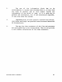
Chapter 7: Conclusions an Recommendations
7.1 Conclusions
It was possible to build a working prototype of the intelligent
alarms expert system on an IBM-AT in the multitasking environment
of MultiDos-Plus. Tests were performed on a second data set that
was obtained from the anesthesia simulator; this is another data
set than the development set. The system was twice as fast
compared to a run in real time. The following malfunctions could
be identified:
-
Incompetent inspiratory valve
Incompetent expiratory valve
Exhausted CO2 absorber
Obstruction at the Y-piece
Obstruction in the inspiratory hose
Obstruction in the expiratory hose
It is expected that leaks and disconnects can also be detected,
but it will be difficult to distinguish between all the leaks and
disconnects. New rules for the leaks and disconnects are
currently under development.
Apart from some unexplainable crashes during startup, MultiDosPlus is good way to do multitasking under the single task
operating system MS-DOS.
7.2 Recommendations
1.
The rules for the disconnect and the leaks have to
be implemented. Extensive tests of the intelligent alarms
system have to be performed with both simulator data and
real patient data. Although it is not possible to
introduce malfunctions while ventilating a real patient
it is important to test the system in a normal situation
to see how it behaves in the real, violent environment of
the operating room.
Intelligent Alerms in Anesthesia
40
2.
The use of the information block has to be
reconsidered; it causes some overhead when it is sent from
one task to another and at this moment hardly any
information of the block is used. It is a good way to
present the information, but if the information expanses,
it may slow down the system.
3.
Implementation of more sensors (second flow device,
ventilator settings) can provide a more accurate detection
of malfunctions.
4.
The way the time constants of the flow and pressure
are calculated has to be reconsidered. They do not provide
a very stable calculation of the time constants.
Intelligent Alar.s in Anesthesia
41
LITERATURE
[AA87]
Aa, J.J. van der
Monitoring the integrity of the circle breathing systp.m
during general anesthesia with mechanical ventilation.
M.Sc. thesis. Department of Electrical Engineering,
University of Florida, Gainesville, 1987.
[BAS87]
Bastings, R.H.A.
Towards the deve~opment of an intelligent alarm system in
anesthesia.
M.Sc. thesis (1987). Faculty of Electrical Engineering,
Eindhoven University of Technology, 1989.
EUT Report 89-E-227
[BL088]
B1om, J.A.
The SIMPLEXYS expert systems toolbox.
Preliminary version of a Ph.D. thesis, chapter 7, to be
submitted to the Eindhoven University of Technology in 1990.
[CHE8S]
Cheney, E.W. and D.R. Kincaid
Numerical mathematics and computing. 2nd ed.
Belmont, Cal.: Wadsworth, 1985.
[C0078]
Cooper, J.B. and R.S. Newbower, C.D. Long, B. McPeek
Preventable anesthesia mishaps: A study of human factors.
Anesthesiology, Vol. 49 (1978), p. 399-406.
[G0087]
Good, M.L. and S. Lampotang,G.L. Gibby, J.S. Gravenstein
Training in anesthesiology: Critical event simulation.
Scientific Exhibit. Annual Meeting of the American Society
of Anesthesiologists, Atlanta, Ga., 10-14 Oct. 1987.
[LIC74]
Lichtiger, M. and F. Moya (eds.)
Introduction to the practice of anesthesia.
New York: Harper & Row, 1974.
[MUL86]
Mu1tiDos, a Multi tasking program for PC-DOS. Program manual.
Nanosoft Associates, 13 Westfield Road, Natick, MA 01760.
1986.
[OHM83]
Ohmeda Modulus II. Operation manual.
Madison, Wis.: Ohmeda, 1983.
Intelligent
Alar~s
in Anesthesia
42
[ORK86]
Orkin, F .K.
Anesthetic systems.
In: Miller, R.D., Anaesthesia. 2nd ed. New York: Churchill
Livingstone, 1986.
[WAT86]
Waterman, D.A.
A guide to expert systems.
Reading, Mass.: Addison-Wesley, 1986.
Teknowledge series in knowledge engineering
Intelligent Alarms in Anesthesia
43
APPENDIX A: Programming tools
The data analysis program and the feature extraction program
are written in C and compiled with the Microsoft C compiler
version 4.0 (at this moment a change to version 5.1 is made). The
expert system is written in SIMPLEXYS and compiled by the
SIMPLEXYS rule compiler and the Turbo Pascal compiler version
4.0.
For the C programs some utility routines, to be used in both
programs, were written. The source code is contained in "uti!. c".
The data analysis routines are contained in "anal. c"; several
include files are needed for this (see fig. A.1). "anal.c" and
"uti!. c" were compiled and Microsofts library utility was used
to put both object files in "alarms .lib". The data analysis
("analyze.c") and the feature extraction ("features.c") have to
be linked with this library.
co2def'.h
p~def'.h
f'lwdef'.h
fl'aMe.h
analco2.c
ana I PI'S. C
analf'lw.c
defines.h
flagdef.h
~~~~~t·
d!:jnaM i c. hh
analyze
C
f eat u res 1---------1_-+•
•
o
bsexpert
IntelLigent Alarms in Anesthesia
44
APPENDIX B: Manual utility routines
error
'" Swmnary
int error( str );
char *str;
pointer to error string to print
'" Description
The funtion error() prints the error string on the screen, prints
a dos error string if possible, and aborts the program that calls
the function.
'" Return Value
No return value.
'" See Also
'" Example
/* exit on error */
char filename[801;
FILE *data;
i f ( ( data = fopen( filename,
"w" ) ) -- NULL)
error( filename );
/* the program is aborted if the file cannot be opened */
InteLligent Alarms in Anesthesia
45
* Swmnary
int
int
int
int
get_features( address, len, queue )
address;
address of message
len;
number of bytes in message
queue;
queue number (1-31)
* Description
The function get_features () gets 'len' bytes for the message
queue 'queue'. The bytes are stored consecutive, starting at
'address', so complex structures can also be send. This function
is designed for the small mOdel of the compiler. That means that
all data is in one segment, and that the addresses only consist
of the offset. An address is a pointer to a variable.
If there is no message in the queue, the function starts waiting
until one arrives.
* Return Value
There is no return value.
* See Also
* Example
/* get a message out of queue 5 */
struct SIGNAL signal_frame[3];
/* defined in "frame.h" */
get_features ( signal_frame, 3*sizeof( struct SIGNAL ), 5
Intelligent Alarms in Anesthesia
)i
46
*
Summary
int get_timet t
char *t;
*
);
pointer to time array;
Description
This function gets the date and time as a string, and stores it
in array ' t ' . The array will contain 26 characters, and has the
form:
Tue Jul 26 15:05:11 1988\0\0
*
Return Value
There is no return value.
*
See Also
*
Example
/* get the time and date */
char current_time[26J;
*/
/* string lenght will always be 26
get_time ( current_time );
printf( "%s\n", current time);
Intelligent Alarms in Anesthesia
47
* Sunnnary
int init_flag( fIg
int flgi
)i
16 bits to be zeroed
* Description
The function init_flag() sets a 16 bits variable to zero. This
can be used for the 16 bits flag structures.
* Return Value
No return value
* See Also
* Example
/* initialize flag structure */
struct C02 FLAG flagi
init_flag( flag
/* defined in co2def.h */
)i
Intelligent Alarms in Anesthesia
48
* Sununary
* Description
The function multi_dos_test, tests whether the program is started
up from DOS or MULTI-DOS. If the program was started from DOS the
function prints an error message, and aborts.
* Return Value
No return value
* See Also
send_features, get_features, get_control, send control
* Example
/* test for multi-dos */
test_queue( queue )j
Intelligent Alarms ln Anesthesia
/* never done if no multi-dos */
49
* Swmnary
int printf_bin( flg );
int flag;
16 bits to be printed
* Description
The function printf_bin() prints a 16 bit variable as O's and
l's. No return is added. This can be used to print a 16 bit flag
structure.
*
Return Value
No return value
* See Also
* Example
/* print a flag */
struct C02_FLAG flag;
/* defined in eo2def.h */
flag.be = 1;
flag.to = 0;
printf_bin( flag );
printf( "\n");
Intelligent Alarms in Anesthesia
50
send_control, getcontrol
.. Sununary
int send_control ( queue, c ) i
int queuei
queue to send to
character to send
char Ci
char get_control( queue )i
int queuei
queue to receive from
.. Description
The functions send_control() and get_control() send or get one
character to or from the specified queue 'queue'. These functions
are built from send_features() and get_features(). Get_control()
\o/aits for a message if no message is available.
* Return Value
Function get_control() returns the character from the queue.
Function send_control() has no return value.
.. See Also
* Example
/* send a character to queue 1 and get it out of there */
char controli
send_control ( 1, "A"
)i
control = get_control( 1
)i
if ( control=='A' ) exit( 1
Intelligent ALarms in Anesthesia
)i
51
send features
*
Summary
int
int
int
int
*
send_features( address, len, queue )i
addressi
address of message
leni
number bytes in message
queuei
queue number (1-31)
Description
The function send_features() sends 'len' bytes to the specified
message queue, starting from 'address'. Complex structures can
also be send, as long as
the data of these structures are
continuous in the memory. This function is designed for the small
model of the compiler. That means that all data is in one
segment, and that the addresses only consist of the offset. An
address is a pointer to a variable.
*
Return Value
There is no return value.
*
See Also
* Example
/* send features to queue 5 */
struct SIGNAL signal_frarne(3]i
/* defined in "frarne.h" */
send_features ( signal_frame, 3*sizeof( struct SIGNAL ), 5 )i
intelligent Alarms in Anesthesia
52
suspend
* Summary
int suspend( nr );
int nr;
task number
.. Description
The function suspend() stops the program and waits for the
character 'G' in its queue; In this case the task number is the
queue number.
*
Return Value
There is no return value.
.. See Also
.. Example
/* suspend the program */
control = get_control( 5 );
if ( control=='S' ) suspend( 1 );
Intelligent Alarms in Anesthesia
53
* Sununary
int test_queue( queue );
int queue;
message queue number
* Description
The function test_queue() tests if there is a message in the
specified queue. This can be used if the program wants to do some
other task while waiting for a message (test the keyboard for a
key for example).
* Return Value
Test_queue() returns 0 if no message is avaiable and returns 1
if there is a message in the queue.
* See Also
send_features,
multi_dos_test
get_features,
send_control,
get_control,
* Example
/* get a message from queue 1 */
/* display keystrokes while waiting */
while ( !test_queue( 1 ) )
{
i f (kbhit()
) printf("%c", getch() );
}
control
=
get_control( 1 )i
Intelligent Alarms in Anesthesia
54
APPENDIX C: OMHEDA 5410 VOLUME MONITOR
This paper describes how an Ohmeda 5410 Volume Monitor can be
interfaced with a IBM AT(XT), in order to get the flow, using the
standard serial port (RS-232).
Signals
According to the 5410 Service Manual (page 36), the 5410
provides an Expired Flow signal at pin 3 of connector J2. The
direction of the signal is given on pin 4 (high is reverse flow).
Jumpers PJ3 and PJ4 have to be jumpered for transducer signals.
The signal on pin 3 will give a pulse for approximately every
3 milliliters of gas flow through the transducer.
Counting pulses
The only thing that has to be done is to count the pulses in
one period of time (e.g. 1 second). The current flow can then be
calculated by: flow := counter*3/delta. 'Counter' is the number
of pulses received in period 'delta' (e.g 1 second). The numeric
value of the flow derived by this formula will be the average
flow over the period 'delta'.
RS-232 IBM AT(XT) interrupts
Because the flow pulses will come at an irregular time
interval, the best way to count them is a method based on
interrupts. The IBM machines provide two hardware interrupt
channels for communications (one for COM1, one for COM2).
Four classes of these hardware interrupts are possible:
00
01
10
11
change in modem status register
transmitter holding register empty
data received
reception error or break condition received
We choose to use the interrupt when data is received. Any of
the other interrupts could also be used. If this interrupt is
enabled it gives a hardware interrupt when pin RD (3 on DB25, 2
on DB9) goes from low to high. Interrupt OB is given if COM2 is
used, OC if COM1 is used. The following part of C code should be
used to initialize the registers of the serial port (COMl).
outp( Ox3fb, 0 )i
outp( Ox3fc, OxOB )i
inp ( Ox3fd ) i
outp( Ox3f9, 1 )i
/*
/*
/*
/*
clear line control register */
set RTS, DTR, user aux input '2 */
read line status register
*/
enable interrupt on data received* /
In order to use any hardware interrupt, the corresponding bit
in the interrupt mask register (IMR) has to be set. For the
communication interrupt of COM1 this is done by:
Intelligent Alarms in Anesthesia
55
in
and
out
aI, 21H
aI, efH
dx, 21H
;get the content of IMR
;set bit for COM1
;send byte
WritinQ an interrupt service routine
Because we use an interrupt to update our counter, we have to
provide an interrupt routine that replaces the current interrupt
routine. Because the Microsoft C compiler doesn't provide a way
to write such a routine, it is written in assembler.
Basics of an interrupt routine:
- push the used registers on stack
- do the tasks you want to do
DO NOT use DOS, because it is not re-entrant
- pop the registers from stack
- IRET instruction
Because we want to use a variable in our interrupt routine
that is shared by our C program, we have to make sure that the
data segment is set to DGROUP (the name the MSC compiler uses for
its small model data segment). If an interrupt is invoked, this
is not automatically done. We also have to make sure that all
names that we use for segments are the same as in the assembler
program. See Microsoft C manual for details.
If the interrupt is a hardware interrupt, the interrupt service
routine should end with:
mov
out
aI, 20H
20H, al
This will clear the 'in service register' so that interrupts at
a lower level as the one just completed, are re-enabled.
When the interrupt service routine is written, the address of
the beginning of the routine has to be placed in the interrupt
vector table. The interrupt vector table occupies 4 bytes
(segment:offset) for every interrupt, starting with interrupt O.
The begin address of the vector table is 0000:0000. The address
for the interrupt service routine OC should thus be written at
(0000:0030 hexadecimal).
Implementation
The interrupt service routine written to get the flow pulses
from the Ohmeda 5410 Volume Monitor replaces the current
interrupt OC routine. COMI is used to connect the flowmeter.
The interrupt routine tests status of the pin carrier detect
(CD) by reading the modem status register. If CD is low the
routine increases the counter, else it decreases the counter.
If pin 3 of connector J2 is connected to data received (RD)
and pin 4 is connected to carrier detect (CD), the counter
represents the volume passed since the last counter reset in
amounts of 3 mI. When time information is known, the flow can be
calculated.
Intelligent Alarms in Anesthesia
56
The pin connections from the Volume Monitor to a DB9 serial
plug are:
5410
1 (ground)
--------,
3 (PULSE)
--------,
4 (EXP FLOW) --------,
PC (DB9)
5 (ground)
2 (RD)
1 (CD)
Li tcrature
Jourdain, R.L.
Programmer's problem solver for the IBM PC, XT & AT.
Englewood Cliffs, N.J.: Brady Communications/Prentice-Hall, 1986.
Ohmeda 5410 and 5420 volume [Jonitor. Service manual.
Madison, Wis.: BOC Group Inc., Product Service Department,
Ohmeda, 1987.
Intelligent Alarms in Anesthesia
57
ISSN 0167-9708
Coden: TEUEDE
(205) Butterweck, H.J. and J.H.F. Ritzerfeld, M.J. Werter
FINITE WORD LENGTH EFFECTS IN DIGITAL FILTERS:~iew.
EUT Report 88-E-205. 1988. ISBN 90-6144-205-2
(206) Bollen, M.H.J. and G.A.P. Jacobs
EXTrNSIVE TESTING OF AN ALCORTiHM FOR TRAVELLING-WAVE-BASED DIRECTIONAL
DETECTION AND PHASE-SELECTION BY USING TWDNFIL ANO EMTP.
EUT Report 88-E-2D6. 1988. IS8N 90-6144-206-0
(207) Schuurman, W. and M.P.H. Weenink
STABILITY OF A TAYLOR-RELAXED CYLINDRICAL PLASMA SEPARATED FROM THE WALL
8Y A VACUUM LAYER.
EUT Report 88-E-2D7. 1988. ISBN 90-6144-207-9
(208) Lucassen, F.H.R. and H.H. van de Ven
A NOTAl ION CONVENTION IN RIGID RDBDT MODELLING.
EUT Report 88-E-208. 1988. IS8N 90-6144-208-7
(209) Jozwiak, L.
MINIMAL REALIZATION OF SEQUENTIAL MACHINES: The method of maximal
adjacencies.
EUT Report 88-E-209. 1988. IS8N 90-6144-209-5
(210) Lucassen, F.H.R. and H.H. van de Ven
OPTIMAL 8DDY FIXED COORDINATE SYSTEMS IN NEWTON/EULER MODELLING.
EUT Report 88-E-210. 1988. IS8N 90-6144-210-9
(211) Boom, A.J.J. van den
Hoo-CONTROL: An exploratory study.
EUT Report 88-E-211. 1988. IS8N 90-6144-211-7
(212) Zhu Yu-Cai
ONITHE ROBUST STABILITY OF MIMO LINEAR FEED8ACK SYSTEMS.
EUT Report 88-E-212. 1988. ISBN 90-6144-212-5
(213) Zhu Yu-Cai, M.H. Driessen, A.A.H. Damen and P. Eykhoff
A"NEW SCHEME FOR IDENTIFICATION AND CONTROL.
EUT Report 88-E-213. 1988.
ISBN 90-6144-213-3
(214) Bollen, M.H,J. and C.A.P. Jacobs
IMPLEMENTATION OF AN ALGORTfHMifOR TRAVELLING-WAVE-8ASED DIRECTIONAL
DETECTION.
Eur Report 89-E-214. 1989. ISBN 90-6144-214-1
(215) Hoei jmakers, M.J. en J.M. Vleeshouwers
EEN MODEL VAN DE SYNCHRONE MACHINE MET GELIJKRICHTER, GESCHIKT VODR
REGELDOELEINDEN.
EUl Report 89-E-215. 1989. ISBN 90-6144-215-X
(216) Pineda de Cyvez, J.
LASER:
A LAyout
Sensitivity ExploreR. Report and user's manual.
EUT Report 89-E-216. 1989. IS8N 90-6144-216-8
(217) Duarte, J.L.
MINAS: An algorithm for systematic state assignment of sequential
machines - computational aspects and results.
EUT Report 89-E-217. 1989. ISBN 90-6144-217-6
(218) KOWP' M.M.J.L. van de
S TWARE SET-UP FOR DATA PROCESSING OF DEPOLARI2ATION DUE TO RAIN
AND ICE CRYSTALS IN THE OLYMPUS PROJECT.
EUT Report 89-E-218. 1989. ISBN 90-6144-218-4
(219 ) Koster, C.J.P. and L. Stok
~ETWORK TO ARTWOR~utomatic schematic diagram generation.
un i<1!port
(220)
A9-E-219. 1989. ISBN 90-6144-219-2
Wi I I elll!.. , F.t1.J.
CONVERSES FOR WRITE-UNIDIRECTIONAL MEMORIES.
EUT Report 89-E-220. 1989. ISBN 90-6144-220-6
(221) Kalasek, V.K.I. and W.M.C. van den Heuvel
L-5WITCH: A PC-program for computing transient voltages and currents during
switching off three-phase inductances.
EUT Report 89-E-221. 1989. IS8N 90-6144-221-4
Eindhoven Universit of Technolo
acu ty 0
ectrlca
nglneerlng
(222)
J6~wiak,
Research Re arts
ISSN 0167-9708
Coden: TEUEDE
L.
THE FULL-DECOMPOSITION OF SEQUENTIAL MACHINES WITH THE SEPARATE REALIZATION
OF THE NEXT-STATE AND OUTPUT FUNCTIONS.
EUT Report 89-E-222. 1989. ISBN 90-6144-222-1
(223) Jozwiak, L.
THE Bit FULL-DECOMPOSITION OF SEQUENTIAL MACHINES.
EUT Report 89-E-223. 1989. ISBN 90-6144-223-0
(224) Book of abstracts of the first Benelux-Japan Workshop on Information and
Communication Theory, Eindhoven, The Netherlands, 3-5 September 1989.
Ed. by Han Vinck.
EUT Report
~224.
1989. ISBN 90-6144-224-9
(225) Hoeijmakers, M.J.
A POSSIBILiTY TO INCORPORATE SATURATION IN THE SIMPLE, GLOBAL MODEL
OF A SYNCHRONOUS MACHINE WITH RECTIFIER.
EUT Report 89-E-22S. 1989. ISBN 90-6144-225-7
(226) ~ah~~i' R.P. and E.M. van Veldhuizen) W.R. Rut£ers, L.H.Th. Rietjens
XP MENTS ON INITIAL BEHAViOUR OF CORONA eEN RATED WITH ELECTRICAL
PULSES SUPERIMPOSED ON DC BIAS.
EUT Report 89-E-226. 1989. ISBN 90-6144-226-5
(227) Bastings, R.H.A.
TOWARD THE DEVELOPMENT OF AN INTELLIGENT ALARM SYSTEM IN ANESTHESIA.
EUT Report 89-E-227. 1989. ISBN 90-6144-227-3
(228) Hekker, J.J.
~ER ANIMATED GRAPHICS AS A TEACHING TOOL FOR THE ANESTHESIA MACHINE
SIMULATOR.
EUT Report 89-E-228. 1989. ISBN 90-6144-228-1
(229) Oostroffi, J.H.M. van
INTELLIGENT ALARMS IN ANESTHESIA: An implementation.
EUT Report B9-E-229. 1989. ISBN 90-6144-229-X