1
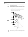
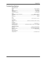
User Manual Edition Notes Edition Notes CHAUVET® released this edition of the Followspot 1200 User Manual Rev. 05 in March 2012. Trademarks CHAUVET® is a registered trademark of CHAUVET & Sons Inc. (d/b/a CHAUVET® or Chauvet). The CHAUVET® logo in its entirety including the Chauvet name and the dotted triangle, and all other trademarks on this manual pertaining to services, products or marketing statements (example: It’s Green Thinking™) are owned or licensed by CHAUVET®. Any other product names, logos, brands, company names, and other trademarks featured or referred to within this document are the property of their respective trademark holders. Copyright Notice CHAUVET® owns the content of this user manual in its entirety, including but not limited to pictures, logos, trademarks and resources. The Followspot 1200 User Manual Rev. 05 covers the description, safety precautions, installation, programming, operation and maintenance of the Followspot 1200. © Copyright 2012 CHAUVET® All rights reserved Electronically published by CHAUVET® in the United States of America Manual Usage CHAUVET® authorizes its customers to download and print this manual for professional information purposes only. CHAUVET® expressly prohibits the usage, copy, storage, distribution, modification or printing of this manual or its content for any other purpose without its written consent. Document Printing For better results, print this document in color, on letter size paper (8.5 x 11 inches), double sided. If using A4 paper (210 x 297 mm), configure your printer to scale the content of this document to A4 paper. Intended Audience Any person in charge of installing, operating and/or maintaining the Followspot 1200 should read the Quick Start Guide that shipped with the Followspot 1200 unit and this manual in their entirety before installing, operating or maintaining the Followspot 1200. Disclaimer CHAUVET® believes that the information contained in this manual is accurate in all respects. However, CHAUVET® assumes no responsibility for any error or omissions in this document. CHAUVET® reserves the right to revise this document and to make changes from time to time in the content hereof without obligation of CHAUVET® to notify any person or company of such revision or changes. This does not constitute in any way a commitment by CHAUVET® to make such changes. CHAUVET® may issue a revision of this manual or a new edition of it to incorporate such changes. CHAUVET® Publications Hot Line If you have any comments about the accuracy of this document or general suggestions regarding how we can improve it, please call us at (800) 762-1084 (US callers) or +1954-929-1115 (international callers), ext. 43. Document Revision The Followspot 1200 User Manual Rev. 05 supersedes all previous versions of this manual. Fixture at a Glance You can download the latest versions of all CHAUVET® products’ manuals from www.chauvetlighting.com. Please discard any older versions of this manual you may have, whether in printed or electronic format, and replace them with this version. Use on Dimmer Outdoor Use Sound Activated DMX Master/Slave Followspot 1200 User Manual Rev. 5 Auto Programs 208/230 V, 50/60 Hz Replaceable Fuse User Serviceable Duty Cycle Table of Contents Table of Contents 1. Before you Begin.............................................................................................................1 What is Included ............................................................................................................................. 1 Unpacking Instructions ................................................................................................................... 1 Text Conventions............................................................................................................................ 1 Icons .............................................................................................................................................. 1 Safety Notes................................................................................................................................... 2 2. Introduction .....................................................................................................................3 System Description......................................................................................................................... 3 Features ......................................................................................................................................... 3 Additional Features .................................................................................................................................... 3 DMX Channel Summary ................................................................................................................. 3 6-channel DMX mode ................................................................................................................................ 3 Product Overview ........................................................................................................................... 4 Product Dimensions ....................................................................................................................... 5 3. Setup ................................................................................................................................6 AC Power ....................................................................................................................................... 6 Power Requirements.................................................................................................................................. 6 Power Cord ............................................................................................................................................... 6 Fuse Replacement ..................................................................................................................................... 6 Voltage/Frequency Selection ...................................................................................................................... 7 Lamp .............................................................................................................................................. 8 Lamp Removal........................................................................................................................................... 8 Lamp Installation ........................................................................................................................................ 9 DMX Linking ................................................................................................................................. 10 DMX Connection ...................................................................................................................................... 10 Mounting ...................................................................................................................................... 11 Orientation ............................................................................................................................................... 11 Rigging .................................................................................................................................................... 11 4. Operation .......................................................................................................................12 Control Panel Description ............................................................................................................. 12 Programming Panel ................................................................................................................................. 12 Navigation Functions................................................................................................................................ 12 Followspot 1200 Menu Options..................................................................................................... 13 Normal Mode ........................................................................................................................................... 13 Offset Mode ............................................................................................................................................. 13 Programming Procedure ............................................................................................................... 14 Normal Mode ........................................................................................................................................... 14 Normal Mode (Cont.)................................................................................................................................ 15 Offset Mode ............................................................................................................................................. 15 External Console .......................................................................................................................... 16 Controls ................................................................................................................................................... 16 DMX Controller Operation............................................................................................................. 17 DMX Values ................................................................................................................................. 17 6-CH........................................................................................................................................................ 17 5. Technical Information ...................................................................................................17 Maintenance................................................................................................................................. 17 Returns ........................................................................................................................................ 18 Claims .......................................................................................................................................... 18 Contact Us ................................................................................................................................... 18 Technical Specifications ............................................................................................................... 19 -a- Followspot 1200 User Manual Rev. 5 Before you Begin 1. Before you Begin What is Included Unpacking Instructions • One Followspot 1200 Fixture • One External Console • One Tripod • One Flight Case • Warranty Card • Quick Reference/Start Guide The Followspot 1200 ships in a flight case, Immediately upon receiving the fixture, carefully unpack the flight case. Check the flight case contents to ensure that all parts are present and that they are in good condition. If any part appears damaged from shipping, or if the flight case shows signs of mishandling, notify the shipper immediately. In addition, retain the flight case and all the packing material for inspection. In any event, save the flight case and all packing material because, in case that you have to return the fixture to the factory, you will have to do so in its original flight case, with all its original packing. See the Claims section in the Technical Information chapter. Text Conventions Convention Meaning 1~512 A range of values 50/60 A set of mutually exclusive values in the text [10] Claims A DIP switch to be configured A fixture function, a new term, a section or a chapter “COLORado™ UM” The name of another publication or manual <SET> Settings MENU > Settings A menu option that can be selected but not modified A sequence of menu options to be followed [1~10] A range of menu values of which one can be selected Yes/No A set of mutually exclusive menu options to choose ON Icons A key to be pressed on the fixture’s control panel Icons A value to be entered or selected Meaning This icon indicates critical installation, configuration or operation information. Failure to comply with this information may render the fixture partially or completely inoperative, damage thirdparty equipment, or cause harm to the user. This icon indicates important installation or configuration information. Failure to comply with this information may prevent the fixture from functioning correctly. Useful information. -1- Followspot 1200 User Manual Rev. 5 Before you Begin Safety Notes Please read the following notes carefully because they include important safety information about the installation, usage and maintenance of this product. It is important to read all these notes before starting to work with this product. There are no user-serviceable parts inside the Followspot 1200. Any reference to servicing this unit you may find from now on in this User Manual will only apply to properly CHAUVET® certified technicians. Do not open the housing or attempt any repairs unless you are one of them. Please refer to all applicable local codes and regulations for proper installation of the Followspot 1200. Keep this manual for future consultation. If you sell the Followspot 1200 to another user, make sure that they also receive this manual. • • • • • • • • • • • • The Followspot 1200 housing weighs 94 lbs (42.6 kg). Always ask for help when mounting this fixture to avoid personal injuries or damage to the unit. Always connect the Followspot 1200 to a grounded circuit to avoid the risk of electrocution. Avoid direct eye exposure to the light source while the Followspot 1200 is on. Lamp explosion hazard! Do not open the lamp cover within five minutes of having turned off the fixture. The bulb remains hot for a long time after turn off. Never touch the bulb barehanded and always hand it by its metallic contacts. Always disconnect the Followspot 1200 from its power source before servicing. Do not touch the Followspot 1200’s housing when operating because it may reach up to 85º C. This product is for indoor use only! To prevent risk of fire or shock, do not expose this product to rain or moisture. Make sure there are no flammable materials close to the fixture(s) while operating. When hanging this fixture, always secure it to a fastening device using a safety cable (not provided). Maximum ambient temperature (Ta) is 104° F (40° C). Do not operate the fixture at a higher temperature. • • • Always make sure that you are connecting the Followspot 1200 to the proper voltage, as per the specifications in this manual or on the product. Never connect the Followspot 1200 to a dimmer pack. Never disconnect the power to the fixture by pulling or tugging on the power cable. Make sure the power cord is not crimped or damaged. • In case of a serious operating problem, stop using this product immediately! In the unlikely event that your Followspot 1200 may require service, please contact CHAUVET® Technical Support. Followspot 1200 User Manual Rev. 5 -2- Introduction 2. Introduction System Description The Followspot 1200 is a DMX compatible follow spot fixture that uses a 1200 W metal halide lamp and features a high efficiency optical assembly, a high quality dichroic color wheel and an external console. This fixture consists of a housing unit that contains the power supply, the control panel, the lamp and the optical assembly. The housing has a yoke for tripod mounting. The Followspot 1200 ships with an external console already mounted on its handle. In addition, the Followspot 1200 includes a stand-alone, adjustable height tripod. The 5-pin DMX input and output sockets for DMX connectivity are on the control panel, while there is another 5-pin XLR socket dedicated to the external console. The Followspot 1200 features a bright 4-digit display and four buttons to perform all its programming functions. The external console features four sliders and several buttons to control the fixture in a stand-alone fashion. However, the user can connect the Followspot 1200 to a DMX daisy chain data link to control it from a standard DMX controller, along with other DMX compatible fixtures. Features • Metal Halide 1200 W lamp • 6-Channel DMX mode • Color Wheel 1 Functions: shutter, iris, color, color temperature, dimmer and focus 8 dichroic colors + white Rainbow color spin at variable speeds Split/Linear Colors • Color Wheel 2 2 dichroic colors + white CTC filter: 3,200 K / Frost / Open Additional Features • Variable electronic iris (4~38⁰) • Variable electronic dimmer (0~100%) • Variable electronic focus • Blackout shutter button • • • External control console Tripod Flight case DMX Channel Summary 6-channel DMX mode DMX Channel Function 1 2 3 4 5 6 Shutter Iris Color Color temperature Dimmer Focus -3- Followspot 1200 User Manual Rev. 5 Introduction Product Overview Fans Housing Control Panel Knob Safety loop Yoke Tripod External Console For details about the Control Panel, refer to the Fuse Replacement and DMX Linking sections in the Setup chapter as well as the Operation chapter. For details about the external console, refer to the External Console section of the Operation chapter. Followspot 1200 User Manual Rev. 5 -4- Introduction Product Dimensions -5- Followspot 1200 User Manual Rev. 5 Setup 3. Setup AC Power The Followspot 1200 has two AC input voltage settings, 208 and 230 VAC, and two AC frequency settings, 50 and 60 Hz. The voltage and frequency settings require changing the connections on the corresponding terminal strip. See the Voltage and Frequency Selection section in this chapter. Always connect the Followspot 1200 to a protected circuit with an appropriate electrical ground to avoid the risk of electrocution or fire. Power Requirements To determine the power requirements for the Followspot 1200 see the label affixed to the fixture. Alternatively, you may refer to the specifications chart in the Technical Information chapter of this manual. The listed current rating indicates the maximum current draw during normal operation. Please refer to the Sizing the Circuit Breakers section in the Appendix chapter of this manual. Power Cord The fixture side of the Followspot 1200’s power cord enters the control panel through a strain relief boot. This side of the power cord is hard-wired to the fixture. Therefore, there is no removable power connector on the control panel. The outlet side of the power cord is bare-ended. This way, the users will be able to equip it with the power plug that best matches the local standards and regulations. Power Cord Pin Out Connection AC Live Wire (U.S.) Wire (Europe) IP-66 Pin Screw Color Black Brown 1 Yellow or Brass AC Neutral White Blue 2 Silver AC Ground Green/Yellow Green/Yellow 3 Green Never connect the Followspot 1200 to a rheostat (variable resistor) or dimmer circuit, even if the rheostat or dimmer channel serves only as a 0 to 100% switch. Fuse Replacement 1) With a Philips screwdriver, unscrew the fuse holder out of its housing and remove the blown fuse from its holder. 2) Replace the blown fuse with a fuse of the exact same type and rating. 3) Replace the fuse holder in its place, and reconnect power. Make sure to disconnect the fixture’s power cord before replacing a blown fuse, and always replace it with a fuse of the same type and rating. Fuse Holder Diagram Illuminated On/off Switch Power Cord Rubber Boot Fuse Holder Followspot 1200 User Manual Rev. 5 -6- Setup Voltage/Frequency Selection The Followspot 1200 uses a single terminal strip to select the operating voltage and frequency. This operation only requires connecting two wires to a terminal strip, as indicated below. Do not connect the fixture to the power outlet without having selected the voltage and frequency first. Make sure that the circuit’s voltage and frequency matches your selection to avoid unstable operation or damage to the fixture. Make sure that there is no power applied to the fixture before opening the fixture’s housing. Opening the Fixture 1) Unfasten the thumbscrew (T) and slide the front cover (FC) slightly forward. 2) Unscrew the two Allen screws (A) and remove the bracket (B). 3) Carefully pick up and slide the back cover (BC) backward, making sure not to pull the wires that run from its fans to the Fan Control PCB inside the housing. B BC A FC Cover Removal Diagram T TS Two black wires arrive to the terminal strip (TS). One wire labeled “1” and the other labeled “2.” 1) Connect the black wires as needed per the table below, without reversing them. 2) Replace the covers. 3) Replace the bracket and secure it with the two Allen screws. Voltage/Frequency Terminal Strip Voltage/Frequency Selection Table Voltage/Frequency Wire #1 Wire #2 208 V, 50 Hz Terminal #2 Terminal #4 208 V, 60 Hz Terminal #2 Terminal #3 230 V, 50 Hz Terminal #1 Terminal #6 230 v, 60 Hz Terminal #1 Terminal #5 -7- Followspot 1200 User Manual Rev. 5 Setup Lamp The user may have to install the lamp before operating the Followspot 1200 for the first time. The instructions below include the steps to remove an existing lamp as well as to install a new lamp. Lamp Removal Removing an already installed lamp requires caution. Follow the steps indicated below to complete the removal in a safe manner. Make sure that there is no power applied to the fixture before opening the fixture’s housing. Lamp explosion hazard! Wait 15 minutes after having turned off the fixture to open the lamp cover. Opening the Fixture 1) Unfasten the thumbscrew (T) and slide the front cover (FC) slightly forward. 2) Loosen the thumbscrew that hold the lamp cover (LC) and lift it to expose the lamp socket. L Lamp Removal Diagram FC T LC Always wear safety goggles and soft gloves when handling the lamp. The bulb remains hot for a long time after turn off. Never touch the bulb barehanded and always hand it by its metallic contacts. Removing an Existing Lamp 1) Once you have access to the lamp, loosen both lamp end screws. 2) Grab the lamp by both lamp end screws, push it evenly against the clips and then slide it upwards until it is free. 3) Place the lamp in an appropriate container for disposal. Always follow local regulations regarding the disposal of used metal halide lamps. Followspot 1200 User Manual Rev. 5 -8- Setup Lamp Installation Installing a new lamp requires caution. Follow the steps indicated below to complete the lamp installation in a safe manner. If you touched the lamp with your bare hands, make sure to clean it thoroughly (contacts, glass necks and glass globe) with isopropyl alcohol and wipe it with a lint-free cloth before installing it. Otherwise, the fingerprints on the lamp may shorten its life and even cause damage to the optical assembly. Follow all the safety instructions indicated on page 8. Installing a New Lamp 1) If installing a new lamp, open the Followspot 1200 as indicated on page 8. 2) Before installing the lamp, loosen its end screws. 3) Hold the lamp by its metallic contacts and slide it into the slots. 4) Ensure that the flat washers on the lamp shafts are on the thumbscrew side of the slot to ensure maximum contact. 5) Evenly push the clips backward to allow the lamp to go all the way into the slots. 6) Rotate the lamp until the nipple is on the top of the bulb. 7) Tighten the lamp end screws. 8) Once installed, the lamp should look as in the diagram bellow. Lamp end screw Flat washer Clip Contact plate Reflector Bulb nipple Lamp Installation Diagram Clip Fixture’s front Lamp contact Lamp end screw Contact plate Closing the Fixture 1) Close the lamp cover and tighten the thumbscrew that holds it. 2) Slide the front cover backward until it touches the bracket. 3) Tighten the thumbscrew to secure the front cover. -9- Followspot 1200 User Manual Rev. 5 Setup DMX Linking If you are using the Followspot 1200 with a DMX controller, you can link them using a regular DMX serial connection. Be aware that the Followspot 1200 uses 5-pin XLR connectors and that you will need a 5-pin to 3-pin adapter in most cases. If you are not familiar with the DMX standard, please refer to the DMX Primer and DMX Connectivity sections in the Appendix chapter of this manual. The Followspot 1200 does not support the Master/Slave mode. DMX Connection The Followspot 1200 uses the regular DMX data connection for its only 6-channel DMX mode. Refer to the Introduction chapter for a brief description of this mode and the Operation chapter to learn how to configure the Followspot 1200 to work in this mode. The diagram below shows the Followspot 1200 DMX connectors. DMX Connectors Diagram DMX Output DMX Input External Console Only Pins 4 and 5 of the External Console Only socket carry power for the external console. Therefore, DO NOT connect the DMX cable to this socket. Otherwise, you could damage the DMX controller or the fixtures connected to the DMX link. 1) Connect the DMX cable that comes from the DMX controller or from the other DMX fixtures to the DMX Input socket. 2) Connect the DMX cable that goes to the other DMX fixtures to the DMX Output socket. When using the Followspot 1200’s external console, DO NOT connect the Followspot 1200 to the DMX link. The diagram below illustrates a typical DMX link connection. DMX Link Diagram Followspot 1200 User Manual Rev. 5 -10- Setup Mounting Orientation Always mount this fixture in any safe position while making sure that there is adequate room around it for ventilation. Make sure to mount this fixture away from any flammable material as indicated in the Safety Notes. Rigging The Followspot 1200 consists of a housing unit and a tripod (included). CHAUVET recommends following the general guidelines below when mounting the Followspot 1200 and its tripod on top of a suitable platform. • When selecting an installation location, consider ease of access to the fixture for operation, programming adjustments and routine maintenance. • Never mount the fixture in places where rain, high humidity, extreme temperature changes or restricted ventilation may affect it. • Make sure that the location where you are mounting the fixture can support its weight (84 lbs / 38 kg) as well as the operator’s weight. Carrying handles (both sides) Tilt adjustment knob (+45 ~-45º) Product Mounting Diagram Safety loop (both sides) Yoke Swivel tripod top Tripod leg As an extra measure to reduce vibrations and to prevent the fixture from tipping over, weight down the tripod arms or anchor them to the mounting platform. -11- Followspot 1200 User Manual Rev. 5 Appendix 4. Operation Control Panel Description The Followspot 1200’s control panel includes the Programming Panel, the Power Panel and the DMX Panel. Refer to page 6 for a description of the Power Panel, and to page 10 for a description of the DMX Panel. The Programming Panel allows the user to configure the Followspot 1200’s functions with a 4-digit blue LED display and four buttons located directly under the LED display. The table below explains the functions of those buttons. Programming Panel Button <MENU> Used to scroll to a function or to return to a previous menu option <ENTER> Selects a menu option <UP> <DOWN> Navigation Functions Display Function Change Function Scrolls through the menu options in ascending (forward) order Scrolls through the menu options in descending (backward) order The Followspot 1200’s navigation functions allow the user to setup all the fixture’s parameters, as described in the Menu Map and the programming procedures. The Followspot 1200’s display has four 7-segment, blue LED modules. To select a function, press <MENU> repeatedly until the desired function shows on the display. Alternatively, if the display shows a function name, you could press <UP> or <DOWN> to look for another function. Function Selection To select a function, press <ENTER>. The display will start blinking. To exit the current function without making any change, press <MENU>. Function Value Press <UP> or <DOWN> to select a value for the current function while the display is blinking. Saving a Value While the display is blinking, press <ENTER> to save the selected value for the current function. Function Timer After selecting a function value, you have eight seconds to press <ENTER> to save the value on the display. Otherwise, the display will exit the current function without saving the new value. Programming Modes The Followspot 1200 has two programming modes, Normal and Offset. The Normal mode is for regular operation, while the Offset mode is for home adjustments. Followspot 1200 User Manual Rev. 5 -12- Appendix Followspot 1200 Menu Options Normal Mode Function st 1 Level nd 2 Level Description DMX Address 1~255 Selects the fixture’s DMX address Color Black Out Yes/No Enables/disables the black out while changing colors Self-test N/A Runs the built-in self-test program Fixture Hours N/A Shows the amount of hours the fixture has been on Lamp On/Off On/Off Reset N/A Turns the lamp on or off Resets the fixture to its factory default settings Offset Mode Function st 1 Level nd 2 Level Description Color Offset -127~127 Performs the fine position adjustment for the color wheel Effect Offset -127~127 Performs the fine position adjustment for the effects wheel Dimmer Offset -127~127 Performs the fine position adjustment for the dimmer -13- Followspot 1200 User Manual Rev. 5 Appendix Programming Procedure The Followspot 1200 programming requires only three menu levels and it uses two programming modes, Normal and Offset. The Offset mode is for home adjustments of the color, the dimmer and the effects. When not in program mode, the display shows the current DMX address. Normal Mode DMX Address The Normal mode controls the DMX address, the control activation, the lamp on/off status, the running of the self-test and the fixture reset. In addition, it shows the number of hours the fixture has been in service. Defines the fixture’s starting address 1) Press <MENU> repeatedly until the display shows 2) Press <ENTER> to show the current DMX address (1~255). The display will start blinking. 3) To exit without changing the value, press <MENU>. 4) To change the address value, press <UP> or <DOWN>. 5) To save the new value, press <ENTER>. The display will show the next function name. Color Wheel Blackout Enables/disables the blackout fixture while changing colors 1) Press <MENU> repeatedly until the display shows 2) Press <ENTER> to show the current setting (Yes/No). The display will start blinking. 3) To exit without changing the value, press <MENU>. 4) To change the setting, press <UP> or <DOWN>. 5) To save the new value, press <ENTER>. The display will show the next function name. Self-test Runs the built-in self-tests 1) Press <MENU> repeatedly until the display shows The display will start blinking. 3) Press <ENTER> to start the tests. The display will stop blinking and the tests will start to run continuously. 5) To suspend the tests for 30 seconds, press <ENTER>. 6) To terminate the tests, press <MENU>. The display will show the next function name. Fixture Hours Shows the number of hours the fixture has been in service 1) Press <MENU> repeatedly until the display shows The display will start blinking. 2) Press <ENTER> to see the number of hours. 3) To exit, press <MENU>. The display will show the next function name. Followspot 1200 User Manual Rev. 5 -14- Appendix Normal Mode (Cont.) Lamp Turns the lamp on or off 1) Press <MENU> repeatedly until the display shows The display will start blinking. 2) Press <ENTER>. The display will show the current lamp status (On/Off). Lamp Off 3) To turn the lamp off, press <UP> or <DOWN> until the display shows off. 4) Press <ENTER> to save the change. The display will stop blinking and the lamp will turn off immediately. In eight seconds, the display will start showing the current DMX address. Lamp On 5) To turn the lamp on, press <UP> or <DOWN> until the display shows on. 6) Press <ENTER> to save the change. The display will stop blinking and the lamp will start to turn on immediately. In eight seconds, the display will start showing the current DMX address. Reset Resets all the settings to their factory defaults 1) Press <MENU> repeatedly until the display shows The display will start blinking. 2) Press <ENTER> to start the defaulting process. The display will stop blinking and it will show 1200. All DMX channels will return to their default settings. The reset function does not affect the Fixture Hours total. Offset Mode Entering Offset Mode The Offset mode provides fine position adjustment for the color wheel, the effects (color temperature) wheel and the dimmer. These fine adjustments allow the operator to position the wheels so the light goes through the center of the color or effect aperture, thus preventing any filter border from showing. In the case of the dimmer, the fine adjustment ensures that at 0% dimmer (maximum light), the dimmer is not affecting the light beam. 1) Press <MENU> for five seconds. The display will show the first offset mode function. Color Offset Performs the fine position adjustment for the color wheel 1) Press <UP> or <DOWN> repeatedly until the display shows 2) Press <ENTER>. The display will start blinking, showing the current value (-127~127). 3) Press <UP> or <DOWN> to set the new value. 4) Press <ENTER> to save the new value or <MENU> to exit without saving. Effect Offset Performs the fine position adjustment for the effects wheel 1) Press <UP> or <DOWN> repeatedly until the display shows 2) Press <ENTER>. The display will start blinking, showing the current value (-127~127). 3) Press <UP> or <DOWN> to set the new value. 4) Press <ENTER> to save the new value or <MENU> to exit without saving. -15- Followspot 1200 User Manual Rev. 5 Appendix Offset Mode (Cont.) Dimmer Offset Performs the fine position adjustment for the dimmer 1) Press <UP> or <DOWN> repeatedly until the display shows 2) Press <ENTER>. The display will start blinking, showing the current value (-127~127). 3) Press <UP> or <DOWN> to set the new value. 4) Press <ENTER> to save the new value or <MENU> to exit without saving. Exiting Offset Mode 1) After you are done, wait eight seconds for the display timer to activate. The display will show the current DMX address. External Console The external console ships already installed on the Followspot 1200 handle. This console has dedicated sliders and buttons to control only the associated fixture. In addition, the external console connects to the Followspot 1200 using a dedicated 5pin XLR connector on the control panel. Pins 4 and 5 of the External Console Only socket carry power for the external console. Therefore, DO NOT connect the DMX cable to this socket. Otherwise, you could damage the DMX controller or the fixtures connected to the DMX link. Controls The external console controls have pre-assigned functions and labels. This simplifies the fixture’s operation. When the Followspot 1200 is in any of its programming modes, the external console is not operational. External Console Diagram Dimmer The dimmer has a Blackout and an Open button. This allows the operator to keep the slider at a fixed position when closing the dimmer to 0% or opening it to 100%. When the dimmer is open after having pressed the Open button, the operator can resume the slider control by gently touching the slider. Resuming slider control after blacking out the dimmer is not possible, however. Shutter The shutter has no fixed position buttons to operate along with the slider. This slider has a closed and an open position on the left side, while the right side has another open position. The shutter frequency changes from short yet separated openings to a fast strobe-like action as the slider moves from left to right. Iris The iris has a Closed and an Open button. As with the dimmer, this allows the operator to keep the slider at a fixed position when closing the iris to its minimum or opening it to its maximum. The slider operation can resume by slightly touching the slider after having set the iris to either its maximum or minimum aperture by using the corresponding button. Focus The focus control has no fixed buttons to operate along the slider, either. The focus changes from near to far as the slider moves from left to right. Color Control The button on the left lower corner of the console determines the way the color changes. If it is in the Fixed Color position, buttons 1 to 9 determine the color. If it is in the Color Scroll position, buttons 1 to 9 determine the scrolling speed (slow to fast). Color Temperature The color temperature control is independent from the color control mode. It has three positions, 6000º K, Frost and 3200º K. Followspot 1200 User Manual Rev. 5 -16- Appendix DMX Controller Operation To operate the Followspot 1200 with a standard DMX controller you will have to assign a starting DMX address on the Followspot 1200. Please refer to the Programming Procedure section of this chapter for instructions. After that, you will have to connect the Followspot 1200 to the DMX link as indicated on page 10 of this manual. Always disconnect the external control console when operating this fixture with a third party DMX controller. DMX Values 6-CH Channel Function Value Percent/Setting 1 Shutter 000 008 016 248 2 Iris 000 254 255 0~100% Closed 3 Color 000 015 029 043 057 071 085 099 113 128 192 White Red Green Blue UV Purple Golden Amber 2,900 K 4,800 K 3,800 K CW Rotation (Fast~Slow) CCW Rotation (Slow~Fast) 4 000 085 Color Temperature 086 170 171 255 6,000 K 5,600 K 3,200 K 5 Dimmer 000 255 0~100% 6 Focus 000 255 Close~Far 007 015 247 255 014 028 042 056 070 084 098 112 127 191 255 Blackout Open Strobe (1~12 Hz) Open 5. Technical Information Maintenance To maintain optimum performance and minimize wear, the user should clean the Followspot 1200 frequently. Usage and environment are contributing factors in determining the cleaning frequency. As a rule, the user should clean the fixture at least twice a month. Dust build-up reduces light output performance and can cause overheating. This can lead to reduced light source life and increased mechanical wear. The cleaning frequency depends on the environment in which the fixture operates. Damp, smoky or particularly dirty surrounding can cause greater accumulation of dirt on the unit’s optics. Even in the cleanest type of surroundings, the user should clean the external optics at least once every 30 days. CHAUVET® recommends cleaning the fixture’s external optics with a soft cloth using normal glass cleaning fluid. To clean the Followspot 1200, follow the below recommendations: • • • • • • • Unplug the fixture from power. Wait until the fixture is cold (15 minutes minimum). Use a vacuum (or dry compressed air) and a soft brush to remove dust collected on the external vents and reachable internal components. Clean all optics and glass surfaces with a mild solution of glass cleaner or isopropyl alcohol, and a soft, lint free cotton cloth or a lens cleaning tissue. Apply the solution directly to the cloth or tissue and drag any dirt and grime to the outside of the lens. Gently polish the glass surfaces until they are free of haze and lint. When cleaning movable mirrors, to avoid scratching or damaging their surface, minimize the contact with the mirror surface to a minimum. Always dry the optics and glass surfaces carefully after cleaning them. If the fixture has fans, never spin them using compressed air. -17- Followspot 1200 User Manual Rev. 5 Appendix Returns The user must send the merchandise prepaid and in the original box with its original packing and accessories. CHAUVET® will not issue call tags. Call CHAUVET® and request a Return Merchandise Authorization Number (RMA #) before shipping the fixture. Be prepared to provide the model number, serial number and a brief description of the cause for the return. The user must clearly label the package with a Return Merchandise Authorization Number (RMA #). CHAUVET® will refuse any product returned without an RMA #. DO NOT write the RMA # directly on the box. Instead, write it on a properly affixed label. Once you are given an RMA #, please include the following information on a piece of paper inside the box: • • • • • Your name Your address Your phone number The RMA # A brief description of the symptoms Be sure to pack the fixture properly. Any shipping damage resulting from inadequate packaging is the customer’s responsibility. As a suggestion, proper UPS packing or double-boxing is always a safe method to use. CHAUVET® reserves the right to use its own discretion to repair or replace returned product(s). Claims The carrier is responsible for any damage incurred during shipping. Therefore, if the received merchandise appears to have damages caused during shipping, the customer must submit the damage report and any related claims with the carrier, not CHAUVET®. The customer must submit the report upon reception of the damaged merchandise. Failure to do so in a timely manner may invalidate the customer’s claim with the carrier. For other issues such as missing components or parts, damage not related to shipping, or concealed damage, the customer must make claims to CHAUVET® within seven (7) days of receiving the merchandise. Contact Us World Wide General Information CHAUVET® 5200 NW 108th Avenue Sunrise, FL 33351 Voice: (954) 929-1115 Fax: (954) 929-5560 Toll free: (800) 762-1084 Technical Support Voice: (954) 929-1115 (Press 4) Fax: (954) 929-5560 (Attention: Service) World Wide Web www.chauvetlighting.com Followspot 1200 User Manual Rev. 5 -18- Appendix Technical Specifications Weight & Dimensions Length ................................................................................................................................. 45.1 in (1,147 mm) Width ...................................................................................................................................... 16.9 in (430 mm) Height ........................................................................................................................................9.0 in (230 mm) Weight (Product only) ............................................................................................................... 94 lbs (42.6 kg) Weight (Stand) ............................................................................................................................ 17 lbs (7.7 kg) Weight (All w/ roadcase) ........................................................................................................ 213 lbs (96.6 kg) Power Selectable Input Voltage and Frequency.........................................................................208/230 V, 50/60 Hz Current draw ................................................................................................... Operating: 8.61 A; Inrush 9.2 A Power ....................................................................................................................................................1,264 W Power Factor......................................................................................................................................... PF 0.71 Fuse External ............................................................................................................. 6 x 30 mm, glass, 15 A, 250 V Light Source Metal Halide Lamp ................................................................. Osram HTI 1200 W/D/7/60, 6,500 K, 2,000 hrs Quantity ............................................................................................................................................................ 1 Photo Optic Luminance (4º angle) ......................................................................................................... 202,000 lux @ 1 m Luminance (13º angle) .............................................7,000 lux @ 5 m; 3650 lux 2 7 meter, 1800 lux @ 10 m Beam angle range ....................................................................................................................................4~38° Control & Programming Data input ..........................................................................................................locking 3-pin XLR male socket Data output ....................................................................................................locking 3-pin XLR female socket Data pin configuration....................................................................................... pin 1 shield, pin 2 (-), pin 3 (+) Protocols ................................................................................................................................. DMX-512 USITT DMX Channels ................................................................................................................................................. 6 Ordering Information Followspot 1200............................................................................................................... FOLLOWSPOT1200 -19- Followspot 1200 User Manual Rev. 5 CHAUVET® th 5200 NW 108 Avenue Sunrise, FL 33351 (USA) Toll free (800) 762-1084, Local 954-929-1115 Fax 954-929-5560 www.chauvetlighting.com Followspot 1200 User Manual-Rev. 5 © Copyright 2012 CHAUVET® All rights reserved. Printed in the P. R. C.