1
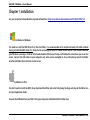
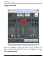
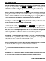
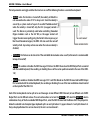
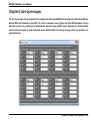
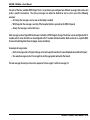
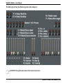
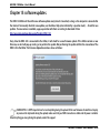
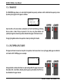
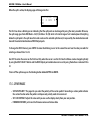
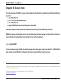
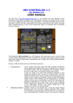
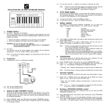
GSi DMC-122 Editor – User's Manual
Editor v. 1.00 – User's Manual
www.GenuineSoundware.com
GSi DMC-122 Editor – User's Manual - 1/42
GSi DMC-122 Editor – User's Manual
Welcome to the user's manual for the GSi DMC-122 Editor. This application for Windows and OS X operating systems lets you configure every
aspect of your DMC-122 in deep detail, making it the perfect control center of your Digital Music world. We recommend that you read this manual
with attention and refer to it every time you have doubts about the usage of the DMC-122.
CHAPTER INDEX
1. Installation
2. Connection
3. Understanding the SetUps
4. Editing buttons
5. Editing drawbars and potentiometers
6. Editing the Encoder
7. Global settings / panel settings
8. Startup Messages
9. Custom Velocity Curves
10. The Library
11. The message monitor
12. Playing the built-in VB3-II
13. Off-line editing
14. Shortcuts
15. Software updates
16. Rear connections
17. LCD menu and other parameters
18. Factory reset
pag. 3
pag. 4
pag. 6
pag. 8
pag. 13
pag. 15
pag. 16
pag. 21
pag. 23
pag. 25
pag. 28
pag. 30
pag. 33
pag. 34
pag. 35
pag. 36
pag. 38
pag. 42
GSi DMC-122 Editor – User's Manual - 2/42
GSi DMC-122 Editor – User's Manual
Chapter 1: installation.
Use your computer to download the required software from: http://www.GenuineSoundware.com/Products/DMC-122
Installation on Windows
You need to install the MIDI driver first, then the Editor. It is recommended not to install and launch the Editor without
having installed the MIDI driver first. Unzip the file containing the driver in a folder of your choice. If you're unsure whether
your Windows is running in 32 bit or 64 bit mode, double-click the icon “Setup.cmd”. Follow the instructions you see on the
screen. Connect the USB cable to your computer only when you're prompted to do so. Once done, launch the Editor
installer and follow the instructions on the screen.
Installation on OS X
You don't need to install the MIDI driver, download the Editor and install it by doing the drag-and-drop of the Editor icon
into your Application folder.
Connect the USB cable from your DMC-122 to your computer and double click the Editor Icon.
GSi DMC-122 Editor – User's Manual - 3/42
GSi DMC-122 Editor – User's Manual
Chapter 2: connection.
Click the button labeled “CONNECT” you see on the top right. This will activate the connection between the Editor and your
DMC-122. If everything is correct, you should see a notice in the red square in the middle of the screen showing your
current firmware version and release date.
GSi DMC-122 Editor – User's Manual - 4/42
GSi DMC-122 Editor – User's Manual
What to do if connection fails:
1. Retry clicking “CONNECT” again;
2. It's likely that the Editor didn't find the DMC-122 MIDI ports. Go to the Midi menu and select both the MIDI Input and
MIDI Output ports, then retry to connect.
3. Double check all your connections. Is the DMC-122 powered on?
When the Editor is connected, the DMC-122 can be considered “on-line” and every action taken with the Editor is
immediately reflected onto the DMC-122.
PLEASE NOTE: Despite the communication being bidirectional, any action taken on the DMC-122 when it's on line is not
immediately shown on the Editor screen. It is recommended not to interact with the DMC-122's editing menu pages
while using the Editor.
2.1 - THINGS TO CONSIDER WHEN THE DMC-122 IS ON-LINE
The Editor checks for connection integrity every time an action is taken. Should connection be lost, an alert would pop up
immediately. In that case, the Editor application must be closed and re-opened.
The MIDI input and output ports are automatically remembered every time the Editor is launched. If the Editor is launched
while the DMC-122 is not connected to the computer, the first available input and output ports will be automatically
selected. The next time the DMC-122 is connected to the Editor, a manual port selection might be required.
GSi DMC-122 Editor – User's Manual - 5/42
GSi DMC-122 Editor – User's Manual
Chapter 3: understanding the SetUps.
The DMC-122 has room for 33 complete SetUps, one of which, the number 0, is a special SetUp specifically made for playing
the built-in VB3-II sound engine. This SetUp can't be deleted, can't be renamed, can't be moved to a different location, but
can be copied to a new location in case one needs to make some modifications.
A SetUp is a memory that holds all the informations related to every single assignment of buttons, potentiometers,
drawbars, etc. To be precise, every SetUp contains the following data:
– Global informations: name (max 12 characters),
description (max 16 characters), memory location, etc.
– All global settings
– All startup messages
– Assignments of all buttons
– Assignments of all pedals
– Assignments of all potentiometers
– Assignments of all drawbars
– Assignments of the encoder and of the multi-selection
button
– 6 Snapshots
– 7 upper drawbar presets
– 7 lower drawbar presets
Fig 3.1 - The structure of a SetUp
GSi DMC-122 Editor – User's Manual - 6/42
GSi DMC-122 Editor – User's Manual
3.1 - DIFFERENCE BETWEEN SETUP, SNAPSHOT AND DRAWBAR PRESET
The button row from 1 to 7 can be used to store up to 6 complete snapshots that can be recalled using buttons numbered 1
to 6, also labeled A to F (button no. 7 will remain unused). A snapshot is an ensemble of each information contained by
every single controller, for example the value of a potentiometer at a certain position, or the value of a button (whether it's
on or off), etc. It's exactly like a preset on a synthesizer that, when recalled from the internal memory, sets all parts of the
synthesizer according to how buttons and potentiometers should be positioned.
Both button rows 1 to 7 and 11 to 17 can be used to store and recall drawbar presets. A drawbar preset holds only the
values of a group of 9 drawbars. Group 1 has drawbars from D1 to D9, group 2 has drawbars from D12 to D20.
A SetUp holds in memory everything shown above.
3.2 – TEMPORARY MEMORY
The DMC-122 has a temporary memory that holds some of the settings in a SetUp even after the unit is powered off and
the SetUp has not been saved. Practically, all Global Settings are accessible from the display menus of the DMC-122 control
panel. Any settings changed in this area will be retained even though the SetUp has not been saved, but they will be lost if
a new SetUp is recalled. This topic will be further discussed in Chapter 7.
GSi DMC-122 Editor – User's Manual - 7/42
GSi DMC-122 Editor – User's Manual
Chapter 4: editing buttons.
All numbered buttons available on the DMC-122 panel can be freely programmed in multiple ways. Of course, the three
buttons below the LC Display are not programmable. There are three types of buttons that can be programmed:
– 20 buttons, numbered 1 to 21 (except 10), are for general purpose MIDI functions;
– 1 multi-select button, also numbered 0/10, has a special functionality;
– 2 function buttons, labeled F1 and F2, can be assigned to MIDI functions or internal modifiers.
4.1 – COMMON SETTINGS FOR ALL CONTROLS
All buttons share two very important settings that are common between all types of buttons and will
also be found for the drawbars, the potentiometers, the encoder and the pedals. These are the MIDI
CHANNEL and the MIDI OUTPUT PORT.
The MIDI Channel selection includes:
1. Any MIDI channel from 1 to 16:
2. Basic Channel: uses the same channel that is set as a Basic MIDI Channel in the Global settings;
3. Upper Channel: uses the same channel that is set for the upper manual;
4. Lower Channel: uses the same channel that is set for the lower manual.
The MIDI Output port selection includes:
1. Upper port: uses the same output ports associated with the upper manual;
2. Lower port: uses the same output ports associated with the lower manual;
3. Control port: uses the output ports set as Control Output Ports in the Global settings;
4. USB Port: uses only the USB MIDI port;
5. MO 1: uses MIDI Output port n. 1;
6. MO 2: uses MIDI Output port n. 2;
7. INT: uses the output port that is mounted on the expansion slot blank panel.
GSi DMC-122 Editor – User's Manual - 8/42
GSi DMC-122 Editor – User's Manual
4.2 – GENERAL PURPOSE ASSIGNABLE MIDI BUTTONS
Click the button on the Editor interface that you wish to program, a red square appears in the middle of the screen showing
the possible editing. The example in Fig. 4.1 shows the editing of button n. 7.
For each MIDI assignable button the following main parameters can be selected:
– Button TYPE
– MIDI Channel
– Output MIDI Port
The rest of the parameters vary according to the selected button TYPE.
Fig. 4.1 – Button to send Continuous Controller
The available Types are:
1. Send CC: Sends MIDI Continuous Controller messages;
2. Send PC: Sends MIDI Program Change events along with Bank selection;
3. Send NRPN: Sends a Non Registered Parameter Number;
4. Send Note: Plays a MIDI Note.
Values can be inserted either by typing the number in the text box or by using the up/down arrows. After all parameters are
inserted, the SEND button (the icon with the arrow facing the MIDI connector) must be clicked in order for the button
definitions to be sent to the DMC-122.
PLEASE NOTE: the definitions won't be held in memory until the entire SetUp is saved using the Library window.
GSi DMC-122 Editor – User's Manual - 9/42
GSi DMC-122 Editor – User's Manual
In case a button is programmed for sending a MIDI Continuous Controller message, as shown in Fig. 4.1, the type must be
“Send CC” and the variable parameters are:
–
–
–
–
CC Number: the CC number 0 to 127;
ON Value: the value sent when the button is on;
OFF Value: the value sent when the button is off;
Latched: sets the button behavior. If this option is checked, the value is alternated between ON and OFF every time
the button is pressed and the corresponding LED shows the current status. If this option is unchecked, the button
acts as a momentary button that is ON when it is pushed and is OFF when it is released.
If Type is set to Send PC, as shown in Fig. 4.2, the button sends MIDI Program Change events
along with the bank number. In this case, the variable parameters are:
– Program Change number: a number from 0 to 127;
– Bank Number: a number from 0 to 127; most keyboard receive only 128 program
change events and only on bank 0.
Fig. 4.2 - Button to send Program
Change
If Type is set to send MIDI NRPN (Non Registered Parameter Number), as shown in Fig. 4.3,
the variable parameters are:
– NRPN Number: a number from 0 to 16383;
– ON Value: a number from 0 to 16383; the OFF value is always 0.
– Latched: acts exactly the same as for CC messages.
Fig. 4.3 - Button to send NRPN
GSi DMC-122 Editor – User's Manual - 10/42
GSi DMC-122 Editor – User's Manual
If Type is set to send MIDI Note, the only variable parameter is the note number from 0 to
127. In this case, the button is always momentary, the note-on event is sent when the button
is pushed, and the corresponding note-off is sent when the button is released. Notes are
always sent with velocity set to 127.
Fig. 4.4 - Button to send MIDI notes
4.3 – THE MULTI-SELECTION BUTTON 0/10
There is one button called MULTI-SELECT because its function is to alternate between six different values of a specific type
of MIDI message. Each value is indicated by means of an LED RING indicator. Each push of this button shifts to the next
value.
In the example shown in Fig. 4.5, the MULTI-SELECT button is programmed to send 6 values
on MIDI CC n. 73. Each of the six values is labeled L1 to L6 corresponding to the six LEDs on
the DMC-122 panel. This button can send MIDI Continuous Controller messages or MIDI
Program Change messages.
This button is also labeled 0/10 because is the 10 th button on the control panel and acts as
number 0 of the numbered keypad (explained later in this manual).
Fig. 4.5 - The MULTI-SELECT
button
GSi DMC-122 Editor – User's Manual - 11/42
GSi DMC-122 Editor – User's Manual
4.4 – THE TWO FUNCTION KEYS F1 & F2
The two buttons located on the left side of the DMC-122 panel, next to the modulation wheels and separated from the
other buttons, are labeled F1 and F2 because they can be used as special function buttons not only for sending MIDI
messages. Functions assigned to these buttons can be:
– Octave shift for upper manual
– Octave shift for lower manual
– Octave shift for both manuals
– Toggle Velocity
– Toggle Aftertouch
– Toggle Sustain pedal
– Toggle modulation wheels
When the function buttons are assigned to one of the internal functions
listed above, they can't be programmed like normal MIDI assignable
buttons.
When set as “toggle” functions, the F1 button acts for the upper manual, the F2 button acts for the lower manual. Example:
if set as “Toggle Velocity”, F1 will turn on or off the velocity feature on the upper manual, and F2 will do the same for the
lower manual.
PLEASE NOTE: the LEDs on these two buttons are only used when they are configured as MIDI assignable buttons.
GSi DMC-122 Editor – User's Manual - 12/42
GSi DMC-122 Editor – User's Manual
Chapter 5: editing drawbars and potentiometers.
Drawbars are potentiometers, with the exception that they have that particular shape and they give the maximum value
when they are fully pulled out (even though this can be changed, as explained in this chapter). For this reason, drawbars
and rotary potentiometers are considered the same thing in the DMC-122 and share the same parameters.
Figure 5.1 shows the editing panel of Drawbar D9. All drawbars and potentiometers can be
programmed to send MIDI Continuous Controller messages that vary from a minimum value
to a maximum value along their coarse according to what is instructed them to do.
The first two parameters are the MIDI Channel and the MIDI Output Port. They are exactly
the same as all other controllers and have the same choices that have been described in the
previous chapter.
The next three parameters allow the choice of a Continuous Controller number from 0 to
127, the minimum and the maximum values to be reached. The button labeled “SWAP
VALUES” simply swaps the min. and max. values in their boxes.
Fig. 5.1 - Editing of a drawbar
Once done, the assignments must be sent to the DMC-122 by pressing the SEND button (the
icon with the arrow facing towards the MIDI connector).
Conventionally, MIDI potentiometers send values along the entire range from the
minimum of 0 to the maximum of 127. The DMC-122 can be programmed with any
range. If the minimum value is greater than the maximum value, the action is
automatically reversed, so the values will decrease as the potentiometer rotates
clockwise and will increase as the potentiometer rotates counterclockwise. Have a
look at the provided examples: Fig. 5.2 shows the behavior of a conventional
Fig. 5.2 - Potentiometer Min = 0 and Max = 127 potentiometer set with Min = 0 and Max = 127; Fig 5.3 shows a potentiometer with
Min = 20 and Max = 100, the action is still straight (increases as is rotated
clockwise) but the range is restricted and the middle value is exactly Min + (Max – Min) / 2, in this case 20 + 40 = 60.
GSi DMC-122 Editor – User's Manual - 13/42
GSi DMC-122 Editor – User's Manual
The Fig. 5.4 shows a potentiometer with
reversed values and a range that goes
from 96 to 12, so values decrease as the
potentiometer is rotated clockwise. The
middle value is calculated with the same
formula as above.
Fig. 5.3 - Potentiometer Min = 20 and Max = 100
Fig. 5.4 - Potentiometer Min = 96 and Max = 12
The action of the drawbars is normally reversed, so the maximum value is reached when the drawbar is fully pulled out, and
the minimum value is reached when the drawbar is fully pushed in. If the minimum value is greater than the maximum
value, the action is reversed and the drawbars will act like the conventional slider potentiometers found on audio mixers.
As shown in Fig. 5.5, the action of a drawbar is normally reversed if compared to
conventional slider potentiometers.
It has to be noted, also, that despite the numbering from 1 to 8 printed on each
drawbar, the effective range of MIDI values is not limited to only 8 steps.
Fig. 5.5 - Drawbar Min = 0 and Max = 127
GSi DMC-122 Editor – User's Manual - 14/42
GSi DMC-122 Editor – User's Manual
Chapter 6: editing the encoder.
The rotary encoder on the DMC-122 is normally used to navigate the LCD menu pages and to
change parameter values. When the instrument is in PLAY mode, i.e. not in EDIT mode, the
encoder can be used to send MIDI messages in various ways. Due to its nature, the rotation of
a rotary encoder has no start and no end, it can only detect whether it's rotating clockwise or
counterclockwise.
The encoder can either be disabled or can be configured as:
– Continuous
– Clockwise / Counterclockwise
– Send Program Change
Fig. 6.1 - Encoder type Continuous
When Type is set to Continuous, the encoder can send a given
MIDI Continuous Controller message ranging from a minimum to a maximum value as the
encoder rotates. When a limit is reached, the value is not incremented / decremented even
though the rotation continues.
When Type is set to CCW / CW, the encoder can send one
specific MIDI Continuous Controller message when it is rotated
clockwise, and another MIDI CC message when it is rotated
counterclockwise. This mode is particularly useful to control
the song pointer of a DAW sequencer.
Fig. 6.2 - Encoder set to CCW / CW
When Type is set to Send Program Change, the encoder sends MIDI Program Change events
ranging from a given minimum value to a maximum value on the selected bank. When a limit Fig. 6.3 - Encoder to send MIDI
is reached, the value is not incremented / decremented even though the rotation continues. Program Change
GSi DMC-122 Editor – User's Manual - 15/42
GSi DMC-122 Editor – User's Manual
Chapter 7: global settings / panel settings.
This chapter has a dual title for a reason. The panel titled “Global Settings” includes all parameters that are global for an
entire SetUp, and are the same parameters that can be accessed directly from the LCD screen of the DMC-122. As
anticipated in Chapter 3.2, the DMC-122 has a temporary memory that holds the global settings even after the unit is
powered off. This situation comes in very handy because none of the physical controllers can be directly edited from the
DMC-122 menu pages, but they can be somehow globally altered by changing some of the global settings.
Just to make an example, if a
given group of drawbars is
assigned to Upper Channel
rather than to a specific
channel, once the Upper
MIDI Channel is changed
from
the
LCD,
those
drawbars will follow the new
channel setting. Or imagine
you have assigned some of
the controls to the Control
Port, which is in turn routed
to the USB output; if you
change the Control Port
from the LCD menus, those
controls will follow the new
port setting.
GSi DMC-122 Editor – User's Manual - 16/42
GSi DMC-122 Editor – User's Manual
So you can dynamically assign new channels or ports to controls without reprogramming them. This, unless you have
assigned specific channels or controls that can't be changed until you use the Editor software.
Now let's give a look at the Global Settings control panel. This panel is divided in three main vertical sections: COMMON,
UPPER and LOWER.
7.1 – COMMON GLOBAL SETTINGS
The first part is for common settings, and the first parameter is the Basic Channel. This is a MIDI channel that can be used a
bit like a “jolly”, i.e. in situations when you don't want to assign a specific channel to a control but you want to change it
dynamically without interfering with the channels associated to the upper and lower manuals and their split zones. For
example, you can have all controls associated to the Basic channel which in turn is set to channel 1, and have the two
manuals on different channels. Once you need to send the manuals to other channels, the controls will still send on channel
1. The moment you set Basic Channel to 2, your controls will send to channel 2 as well.
Same for the Control MIDI Output Port, which is actually not a single port but a group of any combination of the four
available outputs. If you don't want to link a control to a specific port, you can assign it to the Control Port and change this
setting directly from the LCD, so that your control will follow the new setting accordingly.
Next is the Transpose. This setting will shift the keyboard tuning by the selected semitones in the range -12 / +12. Since the
transpose amount is retained in memory like all other Global Settings even after the DMC-122 is turned off, this setting is
always shown in the home page of the LCD screen, so you know whether the keyboards are transposed or not and by which
amount. The following image shows an example of the LCD screen in PLAY mode with transpose set at +2. Note that UP:
says -10, this is because the upper manual has been transposed by one octave down, so -12 + 2 = -10.
0: DMC-122
UP: -10
LO:
+2
GSi DMC-122 Editor – User's Manual - 17/42
GSi DMC-122 Editor – User's Manual
The two Foot Control pedals that can be connected to the DMC-122 are treated as normal potentiometers but can have
their response curve set by the next settings called F.C. 1 Curve and F.C. 2 Curve. The curve can be Linear or Exponential,
and the best choice has to be found according to the type of pedal connected, as not all pedals respond the same way.
The input F.C. 1 can be used in various ways, so the next setting F.C. 1 Type lets us select what we're going to use it for. If an
expression pedal is connected to this input, this must be set to Expression. We can also use this input to connect a Dual
Foot Switch or a Half-Moon switch, the latter is commonly used for controlling the speeds of an organ Rotary effect and is
an accessory available from GSi. Please refer to Chapter 16 for more details about wiring of these accessories.
The next setting lets us select the use of the F1/F2 function keys. As mentioned in Chapter 4.4, the two function keys can be
either used as normal MIDI assignable buttons or can be set to modifier functions.
As previously explained in Chapter 3.1, the Button Row 1 to 7 and the Button Row 11 to 17 can be assigned to functions
other than normal MIDI assignable buttons. The Button Row 1 to 7 can be also be used to store 7 drawbar presets for the
drawbar group D1 to D9 or to store 6 complete snapshots. Button Row 11 to 17 can be used to store 7 drawbar presets for
the drawbar group D12 to D20 or to send MIDI Machine Control messages to control the transport of a recorder.
When Button Row 1 to 7 is assigned to Snapshots, buttons labeled A to F can be used to store and recall snapshot. A
snapshot stores the status of all potentiometers, drawbars and buttons (only latching buttons). To store a snapshot hold
the EXIT / SHIFT button and press a button from A to F. The LCD will confirm the action.
When either of the two Button Rows are set as drawbar presets, up to 7 presets can be stored for each row. To store a preset
press and hold the EXIT / SHIFT button and press the desired button. The LCD will confirm the action.
PLEASE NOTE: snapshots or drawbar presets will be lost if the SetUp is not saved using the Library.
When Button Row 11 to 17 is used to send MMC, buttons 11 to 15 send the following commands to the receiving device:
PLAY, STOP, RECORD, REWIND, FAST-FORWARD. The messages are sent to the Control MIDI Output Port and ID=0.
GSi DMC-122 Editor – User's Manual - 18/42
GSi DMC-122 Editor – User's Manual
The last two settings of the Common Global Settings are related to the MIDI input. The DMC-122 has only one MIDI input
that is shared between the classic DIN5 MIDI connector and the USB-MIDI interface. When a USB cable is connected, the
MIDI input from the DIN5 connector is inhibited.
PLEASE NOTE: the MIDI input from the DIN5 connector can't be used while the Editor is on-line.
From these settings the MIDI IN Channel and the MIDI IN Forward Port can be set. All MIDI messages coming from the MIDI
input will be transformed to use the selected channel and will be forwarded to the selected MIDI Output Port.
7.2 – UPPER AND LOWER GLOBAL SETTINGS
The next two sections of the Global Settings panel are practically identical, with the only difference that the first is related
to the upper keyboard, and the second is related to the lower keyboard.
The first setting is the MIDI Channel, that can be any channel from 1 to 16. Next is a combination of any of the four available
MIDI Output Ports. All notes played on a keyboard will be sent with the selected MIDI Channel an will be routed to the
selected MIDI Output Ports.
The notes can be shifted by one Octave below or above the normal setting. The Octave shifting will be summed with the
global Transpose, so a total amount of -24 to +24 semitones is possible.
Both keyboards on the DMC-122 are velocity and aftertouch sensitive. The next setting is used to select a Velocity Curve.
This setting establishes how a keyboard responds to the force applied to the keys. A total of six curves are available, the
first three are factory hard-coded inside the memory of the instrument, and the last three can be user programmed via the
Velocity Curve panel (please see Chapter 9).
Also the Aftertouch response can be altered via the AT Curve setting. Three curves are available: Exponential 1, Exponential
2 and Linear.
GSi DMC-122 Editor – User's Manual - 19/42
GSi DMC-122 Editor – User's Manual
The last parameters are toggle switches that can turn on or off the following functions associated to a keyboard:
– Velocity: when this function is turned off, the velocity at Note-On is
not measured and a value of 127 is always sent. Since the velocity is
sensed by a system made of a pair of so-called “bubble-contacts”,
when the velocity is turned off, only the first (or upper) contact is
used. This feature is particularly useful when controlling Tonewheel
Organ simulators such as the GSi VB3, as the upper contact will
trigger the note more rapidly giving the feel of a faster response, just
like the old tonewheel organs; the DMC-122 also sends the note-off
velocity which stays always active even when the note-on velocity is
disabled;
– Aftertouch: this feature can be turned on if the controlled device makes some use of it, otherwise it is recommended
to keep it turned off;
– Sustain: this enables or disables the MIDI message CC # 64 on the MIDI Channel and to MIDI Output Port associated
with the related keyboard, thus enabling or disabling the use of the sustain pedal connected to the rear of the DMC122;
–
Wheels: this enables or disables the MIDI messages CC # 1 and Pitch Bender on the MIDI Channel and to MIDI Output
Port associated with the related keyboard, thus enabling or disabling the use of the two modulation wheels located
on the top left of the DMC-122.
Each of the two keyboards can be split so to send messages on two different MIDI Channels, to two different sets of MIDI
Output Ports and at different octaves. The next section allows us to turn the Split On or Off, select the Split Note, select a
combination of any of the four available MIDI Output Ports, select the MIDI Channel and the Octave shift. The split point is
below the selected note. Example: Upper keyboard split is on and split note is C4, upper channel is 1 and split channel is 4.
Every note played below C4 is sent on channel 4, the rest is sent on channel 1.
GSi DMC-122 Editor – User's Manual - 20/42
GSi DMC-122 Editor – User's Manual
Chapter 8: start-up messages.
The start-up messages are very important for a complex and well organized MIDI set-up. Imagine you have connected four
different MIDI sound modules to your DMC-122 such as a computer running plugins and three MIDI expanders, and you
want that, at every song, all devices are automatically prepared to play specific sounds. Normally you should manually
interact with each module to recall the desired sounds. With the DMC-122 start-up messages all this can be done in an
automatic fashion.
GSi DMC-122 Editor – User's Manual - 21/42
GSi DMC-122 Editor – User's Manual
For each of the four available MIDI Output Ports it is possible to pre-configure two different messages that can be sent
under a specific circumstance. The start-up messages can either be disabled or can be sent in one of the following
occasions:
– At startup: the message is sent as soon as the SetUp is recalled;
– With Snapshot: the message is sent only if the Snapshot button is pressed on the DMC-122 panel;
– Always: the message is sent in both cases.
Each message can be of type MIDI Continuous Controller or MIDI Program Change. The former can be configured with CC
number and CC value, the latter can be configured with PC number and Bank number. Both can be set on a specific MIDI
Channel or linked to global channels (Upper, Lower, Controllers).
An example of usage can be:
– the first message sends a Program Change so to recall a specific sound on the sound module connected to that port;
– the second message sends a CC message that sets the appropriate volume for that sound.
The two messages for each port are sent in sequence, first message # 1 and then message # 2.
GSi DMC-122 Editor – User's Manual - 22/42
GSi DMC-122 Editor – User's Manual
Chapter 9: custom velocity curves.
As mentioned in Chapter 7.2, the two keyboards of the DMC-122 are velocity sensitive and six different velocity curves are
available, the first three are factory hard-coded and the other three can be freely edited using the graphical editor shown in
this image:
It is very easy to create a new velocity curve because you can literally draw the curve by interacting with this graph using
the mouse. The graph shows 128 vertical bars , the X-axis represents the input value and the Y-axis represent the
transformed output value. The curve is split in two parts, the split point can be moved by clicking and moving the mouse
over the image. The shape of each part can then be varied by using the two vertical sliders.
GSi DMC-122 Editor – User's Manual - 23/42
GSi DMC-122 Editor – User's Manual
To start editing your velocity curve, first select the number of the curve you're going to edit, then click “Get Curve” just to
make sure that you're retrieving the actual data stored inside the DMC-122 internal memory. Then do your editing. You can
test it live by activating the curve from the Global Settings and by sending the curve clicking on the button “Send Curve”
every time you want.
The button labeled “Store” saves a copy of the curve on the hard drive of your computer, just in case you wish to take a copy
to further edit later.
The button labeled “Reset” will draw a linear curve, i.e. every output value equals the input value. You'll see a straight line
going from bottom to top from left to right (yes, we're practically speaking about the hypotenuse of a right triangle).
PLEASE NOTE: the velocity curves are stored globally and are retained in memory as soon as the button “Send Curve” is clicked.
They are not stored in SetUps. The instrument comes factory with empty curves.
9.1 – WHY VELOCITY CURVES ARE IMPORTANT
The keyboards are scanned by a very fast CPU that tries to figure out the force that is applied by the musician on the keys
and tries to translate this physical force to a digital information that is later translated in musical expression. This is a very
complex process that is very hard to accomplish properly and has a strict relationship with the human feeling of playing a
musical instrument and the way it reacts to his body movements. Every experienced musician knows that it takes years to
become confident with his instrument, and this is particularly true with acoustic instruments. However, despite the DMC122 being a digital instrument, it is also intended to control sounds that mimic acoustic instruments such as a grand piano,
or electro-mechanical instruments such as the electric pianos. Having a well balanced velocity curve helps enjoying the
experience of playing a digital instrument and increases the realism of the keyboard response, even though the keyboard is
not of the correct type for a specific sound, i.e. a semi-weighted waterfall keybed could be hardly accepted by a pianist for
playing the piano sound, but with the right velocity curve it can still be well enjoyable.
GSi DMC-122 Editor – User's Manual - 24/42
GSi DMC-122 Editor – User's Manual
Chapter 10: the library.
The DMC-122 Editor is used to edit all settings and parameters but is also, of course, the librarian that allows us to store,
recall, organize, export, import and backup the 32 user SetUps. And here comes the Library panel.
This window is split in two parts: on the left we have the list of all SetUps, from 0 to 32 (remember, SetUp n.0 is the factory
SetUp that can't be deleted, moved, renamed or overwritten). It is possible to scroll the list using the scroll bar or enlarge
the window vertically to view them all at once. The list shows three columns: the SetUp number, the name and the
description.
GSi DMC-122 Editor – User's Manual - 25/42
GSi DMC-122 Editor – User's Manual
It is possible to interact with the list in two ways:
1. double-clicking on a list item allows to quickly recall a SetUp;
2. dragging and dropping items over the list allows us to move them in order to reorganize the list according to a
desired order.
PLEASE NOTE: a double-click on an empty item won't take any action. Drag and drop of a list item makes it possible to
move a SetUp to an empty slot, or to swap two SetUps. Of course, dragging an empty slot over another empty slot will
have no effect.
In order to rename a SetUp or set a new description, first select the desired SetUp by doing a single click on the list item,
the write the name or the description and use the appropriate SET button. Allowed characters are only letters from A to Z,
either uppercase or lowercase, the space and the numbers from 0 to 9. The name can be max. 12 characters long, and the
description can be max. 16 characters long.
10.1 – INTERACTING WITH SETUPS
The right side of the Librarian window shows a list of buttons here explained in detail:
RECALL: this button recalls the selected SetUp, it has the same effect as double-clicking on a list item. The same action can
also be performed from the DMC-122 menu, it is the first menu page as shown in the following image:
GSi DMC-122 Editor – User's Manual - 26/42
GSi DMC-122 Editor – User's Manual
WRITE: click this button to write a SetUp into the DMC-122 internal memory after you have made all your editing. This
button will write the SetUp on the selected location, so first make sure you have selected an empty slot or you are
overwriting the correct SetUp.
PLEASE NOTE: this operation might take some while (roughly 3 to 6 seconds). It is recommended not to play any notes
nor to do any other action while a SetUp is being saved.
DELETE: click this button to delete the selected SetUp. After deletion, the selected slot will become empty.
PLEASE NOTE: this operation can not be undone. Pay attention not to delete a SetUp that you wanted to keep.
IMPORT: click this button to import a single SetUp that you had previously exported to a file onto your computer's harddrive. The new SetUp will be imported on the selected slot thus overwriting everything was previously present on that slot.
EXPORT: click this button to export the selected SetUp to a file onto your computer's hard-drive. This will save a single
SetUp with the extension *.dmc that you can recall later or exchange with other DMC-122 users.
UPLOAD LOCAL: this button will move everything from the local off-line editing temporary memory to the selected slot.
Please refer to Chapter 13 for more details about the off-line editing.
BACKUP: click this button to backup the entire memory content of your DMC-122 to a single file onto your computer's harddrive. This will write a file containing all 32 SetUps that can later be restored using the RESTORE button.
RESTORE: use this function to restore an entire backup that was previously saved.
PLEASE NOTE: this operation might take a long while (up to 1 minute). It is recommended not to play any notes nor to
take any action with the Editor during this operation.
GSi DMC-122 Editor – User's Manual - 27/42
GSi DMC-122 Editor – User's Manual
Chapter 11: the message monitor.
How can you make sure that you're sending the correct MIDI data if you can't see it? Here comes handy a built-in MIDI
Monitor that displays a continuous list of all MIDI messages that are sent by the DMC-122 and are received by the Editor.
This window displays all incoming messages in detail and differentiates them using colors. Only the last 200 messages are
displayed, so the buffer memory is cyclically updated. However, it is recommended to use this window only if really
necessary and not to leave it open while playing, in order to save system resources.
GSi DMC-122 Editor – User's Manual - 28/42
GSi DMC-122 Editor – User's Manual
Columns are:
– Timestamp: the time in milliseconds elapsed since the window was open
– First byte or Message type: a literal name of the message type that can be any of Note-On, Note-Off, Controller,
Program Change, Aftertouch, Pitch Bender;
– MIDI Channel
– Second byte or value: MIDI messages can be three or two bytes long. The first bytes always contains the message
type and the channel. Notes and Controller messages are three byte messages, so this column will display the Note
number (and musical name) or the Controller number; Program Change are two byte messages, the current program
number will be displayed in this column; NRPN, despite being intended as special 14-bit controllers, are sent under
the form of two consecutive MIDI Controller messages;
– Third byte: in case of Notes, this is the velocity value; in case of Controller, this is the actual value (from 0 to 127).
Speaking of velocity, it is worth noting that the DMC-122 always sends the Note-Off velocity, i.e. the force applied during the
release of every key.
Special messages such as the Pitch Bender use three bytes but the last two are merged together in order to form a single 14
bit value.
PLEASE NOTE: this window will show only message arriving towards the Editor, i.e. from the DMC-122 to your computer.
It does not display messages going out of the other three MIDI output ports as these are not connected to the Editor.
GSi DMC-122 Editor – User's Manual - 29/42
GSi DMC-122 Editor – User's Manual
Chapter 12: playing the built-in VB3-II.
The DMC-122 Editor contains the sound engine of GSi VB3-II, a tonewheel organ simulation. To play VB3-II it is necessary to
have a good and stable computer, either Windows or Mac OS X, equipped with a good low-latency sound card. For a
Windows computer, it's strongly advised to have a sound card with ASIO drivers. Many modern Apple computers should
not have problems to run low-latency audio using the built-in sound device, but the sound quality is low and the stability is
not assured. A good USB sound card with a good low-latency driver is always the best solution for a serious music maker.
GSi DMC-122 Editor – User's Manual - 30/42
GSi DMC-122 Editor – User's Manual
To invoke the VB3-II window go to the menu AUDIO and click Open Audio Panel. Make sure that the DMC-122 is connected
and is on-line. Two main parameters are present in this window:
– Audio Driver: your computer might have more than one audio output device, make sure you are selecting the correct
one. If it's a Windows computer with ASIO drivers installed, only ASIO devices will be shown. Only the first two
channels will be used.
– Buffer Size: this parameter influences the audio latency. A lower value would produce less latency but would stress
the CPU, so make sure you are selecting a value which is a good compromise between latency and stability.
Something in the ranges 88 – 128 – 192 – 256 is the best choice. Anyway, the last word goes to the audio device: if
you select a very low value, it's likely that the audio device adjusts it to the minimum value it can accept.
Two further options appear in this window:
– Recall Default SetUp: this will automatically recall SetUp n.0 before activating the audio;
– Auto-Send Snapshot: this will automatically send the entire snapshot of all controls so that the audio starts
synchronized with the physical controls.
The VB3-II tonewheel organ engine included in the DMC-122 Editor is exactly the same as found on the Crumar Mojo organ,
except that this version has no editing parameters and only responds to the commands configured on the DMC-122 panel.
The SetUp n.0 is specifically intended for controlling the VB3-II sound and by default accepts the optional GSi Half-Moon
switch to be connected to the F.C. 1 pedal input, and a 10K linear expression pedal to be connected to the F.C. 2 pedal
input.
What to do if audio fails to start or if you experience pops and clicks:
1.
2.
3.
4.
double check your sound card driver
make sure you have selected the correct audio driver
make sure you haven't set a buffer size too low
check that your computer meets the minimum requirements: any Windows or Mac computer born after 2010.
GSi DMC-122 Editor – User's Manual - 31/42
GSi DMC-122 Editor – User's Manual
The following chart shows the default assignments used in SetUp n. 0:
PLEASE NOTE: closing the audio window will not stop the audio stream.
GSi DMC-122 Editor – User's Manual - 32/42
GSi DMC-122 Editor – User's Manual
Chapter 13: off-line editing.
The DMC-122 Editor can also be used as an off-line SetUp editor. This feature is particularly useful in case you don't have
your DMC-122 near you but you need to prepare a SetUp for a concert or for a particular situation and you wish to save
some time by anticipating the job. Everything you can normally do when the DMC-122 is on-line can also be done when the
DMC-122 is not connected, and every assignment is stored in a temporary memory.
Things that can not be done when the DMC-122 is off-line:
1. The Library can't be used;
2. The MIDI Monitor can't be activated;
3. The VB3-II sound engine can't be played.
You can however save your off-line SetUp in a file onto your computer's hard-drive or you can load some previously saved
file by using the commands of the menu “File”.
Once the DMC-122 is back on-line, a SetUp can be sent to it in two ways:
1. if the SetUp was saved to file, it can be imported using the Library window as explained in Chapter10;
2. if the SetUp has not been saved yet but is still into the temporary memory (i.e. the program has not been closed or a
new SetUp has not been created), it can be uploaded to the DMC-122 using the Library windows and the button
UPLOAD LOCAL.
If the temporary memory contains a modified SetUp that has not been saved yet, an alert will pop-up when the application
is closed or when a connection with the DMC-122 is requested.
GSi DMC-122 Editor – User's Manual - 33/42
GSi DMC-122 Editor – User's Manual
Chapter 14: shortcuts.
The DMC-122 offers a few shortcuts in both the Editor and the hardware that somehow facilitate the work flow.
14.1 – SHORTCUTS IN THE EDITOR
It is possible to copy and paste the assignments of a control to another control of the same type. For example, if we are
editing a button and we want to configure an entire button row to send the same messages with only a single value of
difference, we can copy the first button using the menu Edit → Copy function (or the keyboard shortcut CTRL-C on
Windows and Command-C on OS X) and then paste it to the next button using the menu Edit → Paste (or the keyboard
shortcut CTRL-V on Windows or Command-V on OS X). The Copy-Paste pattern doesn't work if we try to paste on a different
type of control.
14.2 – SHORTCUTS IN THE HARDWARE
The EXIT button is also labeled as a SHIFT button because it allows shift operation on a few other buttons, as explained
below:
– Press EXIT + MULTI-SEL 0/10 to quickly recall the SEND PROGRAM page. This page lets you quickly send a program
change to any combination of the 4 MIDI Output ports. A program change number from 0 to 999 can be sent by
typing the desired number using the buttons numbered 0 to 9 of the PROGRAMMABLE A group.
– Press EXIT + Button 8 to decrease the Transpose by one semitone;
– Press EXIT + Button 9 to increase the Transpose by one semitone;
– Press EXIT + the snapshot button to send a Panic! (i.e. stop any possible hanging note)
GSi DMC-122 Editor – User's Manual - 34/42
GSi DMC-122 Editor – User's Manual
Chapter 15: software updates.
The DMC-122 Editor will check for new software updates every time it is launched, as long as the computer is connected to
the internet. To manually check for new updates, use the Menu Help (also indicated by a question mark) → Check for new
updates. If a new version is available, a pop-up window will inform us inviting to download it from:
http://www.GenuineSoundware.com/Products/DMC-122
Every time the DMC-122 is connected to the Editor, it will check for a new firmware update. If the Editor contains a new
firmware, an alert will pop-up inviting us to perform the update. Not performing the update inhibits the connection of the
DMC-122 to the Editor. The Firmware Uploader windows shows as follows:
PLEASE NOTE: it is VERY important not to touch anything during the upload of the new firmware. Be careful not to play
any note on the keyboards during the upload, make sure that your MIDI connection is stable and AC power is reliable.
Should anything go wrong during the upload, contact the support.
GSi DMC-122 Editor – User's Manual - 35/42
GSi DMC-122 Editor – User's Manual
Chapter 16: rear connections.
The rear panel of the DMC-122 offers the following connections:
From 1 to 6: All MIDI connections explained as follows:
– Socket n.1 is the MIDI Output INT-ernal which is mainly intended for the optional DSP board that can be inserted in
the expansion slot, but while the board is not present, its MIDI port is offered as a 4 th external output.
– Sockets n. 3 and n. 5 are respectively MIDI Output ports n. 1 and n. 2.
– Socket n. 4 is the main MIDI Output and is connected in parallel to the USB-MIDI output, so everything sent to the
USB MIDI port will be found at this socket as well.
– Socket n. 2 is the only MIDI input available in the DMC-122 and is accessible either from this DIN5 port or from the
USB-MIDI port. When the DMC-122 USB-MIDI output is connected to a computer, the USB connection takes the
priority over the MIDI DIN5 input. It's not possible to use them together.
– Socket n. 6 is the USB-MIDI connection that offers both IN and OUT.
Sockets 7, 8 and 9 are inputs for pedals:
– Socket n. 7 is the main Expression Pedal input that can also be programmed to be used with a dual channel footswitch or with a 3-way half-moon switch.
– Socket n. 8 is the second Expression Pedal input that can only be used with continuous pedals.
– Socket n. 9 is the Sustain Pedal input. The polarity for this pedal can be selected in the menu settings.
GSi DMC-122 Editor – User's Manual - 36/42
GSi DMC-122 Editor – User's Manual
The Power section includes:
– Socket n. 10 is a USB 5 Volt power port that can offer up to 500 mA of power for external devices such as a cell phone,
a tablet, a reader's light, a portable fan... whatever needs 5 Volts and won't take more than 500 mA.
– Socket n. 11 and n. 12 are respectively the AC adapter power supply input and the Mains switch.
PLEASE NOTE: a Power Supply Unit is provided with the DMC-122 capable of offering 9 V up to 3 A. Despite the total
power consumption of the DMC-122 will hardly exceed the 600 mA, extra power is offered in case a DSP Expansion
board is installed. For this reason, it's strongly advised to use only the original PSU or a similar model with the same
specifications.
16.1 – ACCESSORY SPECIFICATIONS
The accessories that can be connected to the F.C. 1 port, as explained in the previous page, can be an
expression pedal, a dual foot-switch or an half-moon switch. These can be exactly the same accessories
that can be connected to the REMOTE port of the GSi BURN.
Fig 16.1 - A TRS jack
– If connecting an expression pedal, make sure that the potentiometer inside
your pedal is a 10 Komh linear and the wiper is connected to the ring of the TRS
jack (Fig 16.2). Other type of pedals won't work.
Fig. 16.2 - Expression Pedal wiring
– If connecting a dual foot-switch, it can have both mechanically latched
switches or momentary push buttons. You can find a diagram in the “BURN
Footswitch How-To” PDF document that you find on the GSi website.
– If connecting an half-moon switch, make sure the common contact of the 3-way switch is connected to the ring of the
TRS jack.
GSi DMC-122 Editor – User's Manual - 37/42
GSi DMC-122 Editor – User's Manual
Chapter 17: LCD menu and other parameters.
The programmer interface of the DMC-122 is composed by a 3-line by 16 characters
LC Display, three buttons and a rotary encoder. As already mentioned in Chapter 7,
the display menu allows to access all global parameters of a SetUp plus other
functions specific to the hardware.
To access the menu, press ENTER/MENU, the button LED will light steady; use the
rotary encoder to browse pages; to enter a page or to confirm an action press
ENTER/MENU, the button LED will start blinking; to exit from a page, to cancel an
action or to exit the edit mode and get back to the normal play mode, use the EXIT
button.
As mentioned earlier in this manual, the EXIT button acts also as a SHIFT button for
second functions such as quickly recall the SEND PROGRAM page or set the semitone
transposition.
The button showing a camera is called SNAPSHOT and is used to instantly send all current values of each single control.
Buttons are sent only if are set as latched. By pressing SHIFT + SNAPSHOT a “MIDI Panic!” is sent in case strange things
happen such as hung notes on the receiving MIDI devices.
Pages worth of a special mention, that will be explained in this chapter, are:
– RECALL SETUP
– SEND PROGRAM
– TRANSPOSE
– SPLIT UPPER & SPLIT LOWER
And the last three pages: SUSTAIN POLARITY, SET LCD CONTRAST and FIRMWARE VERSION.
GSi DMC-122 Editor – User's Manual - 38/42
GSi DMC-122 Editor – User's Manual
17.1 – RECALL SETUP
This is the first page of the Edit menu and has already been explained in Chapter 10.1. This page is very important because
lets us to recall a new SetUp that can completely change every single assignment of all physical controls.
17.2 – SEND PROGRAM
This page offers the possibility to send MIDI Program Change events to the connected devices. By entering this page you'll
see something like this:
SEND PROGRAM
___
Canc
Send
USB
At the same time, you will see the four LEDs on the buttons numbered 18,
19, 20 and 21 blinking. A blinking LED indicates that using the related
button does some action. Those four buttons are also labeled USB, MO 1,
MO 2 and INT, which are the abbreviated names of the four MIDI Output
ports; and in fact those four buttons are used to select the MIDI Output
port, or a combination of them, to be used for the action being displayed by the LCD screen. In this example, we are going
to send a MIDI Program Change to the USB-MIDI port only. If we press the MO 1 button, the “MO1” label appears next to
“USB” indicating that the Program Change event will be sent to both those ports.
The Program Change number can be typed using the buttons numbered 0 to 9 and a number from 0 to 999 can be inserted.
To delete the last digit, press the EXIT button which is indicated by the “Canc” abbreviation, and to send the event press the
ENTER button which is indicated by the “Send” abbreviation.
Program Change numbers from 0 to 127 will be sent with Bank 0. The bank number is automatically calculated according to
the Program Change number.
GSi DMC-122 Editor – User's Manual - 39/42
GSi DMC-122 Editor – User's Manual
17.3 – TRANSPOSE
The TRANSPOSE page allows us to select both the global transpose by semitones and the individual transpose by octave.
By entering this page, the LCD appears as follows:
TRANSPOSE
By Semitone:
0
OCT. Up: 0 Lo: 0
Also, the LEDs on the two buttons numbered 8 and 9 will start blinking, indicating
that an action is taken if they are pressed. In this case, using these buttons will
cyclically change the octave transposition related to the upper or the lower manual.
Changing the global semitone transposition is done by rotating the Encoder.
17.4 – SPLIT UPPER & SPLIT LOWER
The Upper and Lower manuals can be split in two portions. Each manual has its own split page, both pages are identical.
Let's take the SPLIT UPPER page as an example:
SPLIT UPPER
OFF
A display like this indicates that there's no split configured for the upper manual, and
the button LED n. 8 will blink, indicating that by pressing that button the SPLIT can
be activated on the upper manual.
GSi DMC-122 Editor – User's Manual - 40/42
GSi DMC-122 Editor – User's Manual
When the split is active, the display page will change into this:
SPLIT UPPER
_C5
Ch:
4
Oct:
0
USB
The first line shows a blinking cursor indicating that the split point can be changed by using the rotary encoder. Of course,
the split range goes from MIDI Note n. 36 (C3) to Note n. 96 (C8) which is the total range of a 61 note keyboard. Everything
below the split point is the split zone that sends notes on the selected split channel, transposed by the selected octave and
towards the selected combination of MIDI Output ports.
To change the MIDI Channel, press ENTER to move the blinking cursor to the second line and use the rotary encoder for
selecting a channel from 1 to 16.
Use EXIT to return the cursor on the first line. Only when the cursor is on the first line the Octave can be changed cyclically
by using the MULTI-SELECT button and the MIDI Output port combination can be set by using the buttons numbered 18 to
21.
To turn off the split zone, press the blinking button labeled UPPER or LOWER.
17.5 – OTHER PAGES
– SUSTAIN POLARITY: this page lets you select the polarity of the sustain pedal. If connecting a sustain pedal activates
the sustain function when the pedal is not depressed, polarity needs to be reversed.
– SET LCD CONTRAST: adjust this value until you can see the display clearly from your seat position.
– FIRMWARE VERSION: just shows the firmware version and release date.
GSi DMC-122 Editor – User's Manual - 41/42
GSi DMC-122 Editor – User's Manual
Chapter 18: factory reset.
The internal memory of the DMC-122 can be entirely wiped and restored to factory conditions by performing the following
procedure:
1. turn off the DMC-122;
2. press and hold the ENTER/MENU button;
3. turn on the DMC-122;
4. keep the ENTER button pressed until the process is terminated.
It would be a good practice to perform an entire backup using the Library window before doing a full reset.
BEWARE: this process will completely erase all user 32 SetUps from the internal memory, and will reset the LCD Contrast
value and the Sustain Pedal polarity. The custom Velocity Curves will not be deleted.
18.1 – QUICK RESET
There's a quick way to reset the DMC-122 avoiding to power it off and on again: simply press the SHIFT + SNAPSHOT like
when sending a normal MIDI Panic! and keep the two buttons pressed until the unit does the re-boot.
The GSi DMC-122 is designed and built in Italy by Guido Scognamiglio and Andrea Agnoletto - VM Connection. All rights reserved.
Any trademarks used in this manual are the property of their respective owners. Windows is a trademark of Microsoft Corporation. OS X is a trademark of Apple. Crumar is
a trademark owned by VM Connection.
V.M. Connection - Via Pascoli 44/A - 30020 Quarto d'Altino – VE - Tel: 0039.0422.474.486
www.GenuineSoundware.com
GSi DMC-122 Editor – User's Manual - 42/42