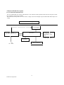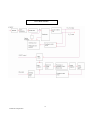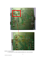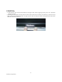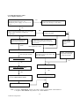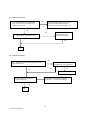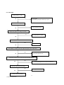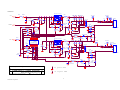
1
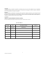
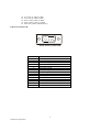
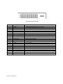
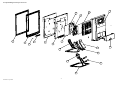
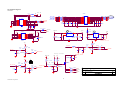
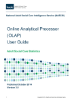
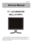
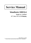
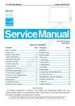
Service Manual
ViewSonic VX715
Model No VS10057
17” Color TFT LCD Display
Manufacture Date: Jan-10-05
Copyright
Copyright@ 2004 by ViewSonic Corporation. All rights reserved. No part of this publication may be reproduced,
transmitted, transcribed, stored in a retrieval system, or translated into any language or manual or otherwise, without the
prior written permission of ViewSonic Corporation.
Disclaimer
ViewSonic makes no representation or warranties, either expressed or implied, with respect to the contents hereof and
specifically disclaims any warranty of merchantability of fitness for any particular purpose. Further, ViewSonic reserves
the right to revise this publication and to make changes from time to time in the contents hereof without obligation of
ViewSonic to notify any person of such revision or changes.
Trademarks
Optiquest is a registered trademark of ViewSonic Corporation.
ViewSonic is a registered trademark of ViewSonic Corporation.
All other trademark used within this document is the property of their respective owners.
Revision History
Revision
Date
Description of changes
A00
Jan-10-05
Initial Release
2
ViewSonic Corporation
Approval
TABLE OF CONTENTS
1. Precautions and Safety Notices
4
2. Specification
5
3. Front Panel Function Control Description
8
4. Function Module Description
14
5. Adjusting Produce
20
6. Trouble Shooting Flow Chart
28
7. Recommended Spare Parts List
34
8. Exploded Diagram and Spare Parts List
45
9. Block Diagram
47
10. Schematic Diagram
48
11. PCB Layout Diagram
53
3
ViewSonic Corporation
1.Precautions and Safety Notices
1.1 SAFETY PRECAUTIONS
This monitor is manufactured and tested on a ground principle that a user’s safety comes first. However, improper use
or installation may cause damage to the monitor as well as the user. Carefully go over the following WARNINGS
before installing and keep this guide handy.
WARNINGS
z This monitor should be operated only at the correct power sources indicated on the label on the rear end of the
monitor. If you’re unsure of the power supply in your residence, consult you local dealer or power company.
z Use only the special power adapter that comes with this monitor for power input.
z Do not try to repair the monitor yourself as it contains no user-serviceable parts. This monitor should only be
repaired by a qualified technician.
z Do not remove the monitor cabinet. There is a high-voltage part inside that may cause electric shock to human
bodies, even when the power cord is unplugged.
z Stop using the monitor if the cabinet is damaged. Have it checked by a service technician.
z Put your monitor only in a clean, dry environment. If it gets wet, unplug the power cable immediately and consult
your service technician.
z Always unplug the monitor before cleaning it. Clean the cabinet with a clean, dry cloth. Apply non-ammonia based
cleaner onto the cloth, not directly onto the glass screen.
z Keep the monitor away from magnetic objects, motors, TV sets, and transformer.
z Do not place heavy objects on the monitor or power cord.
1.2 PRODUCT SAFETY NOTICE
Many electrical and mechanical parts in this chassis have special safety visual inspections and the protection afforded
by them cannot necessarily be obtained by using replacement components rated for higher voltages, wattage, etc.
Before replacing any of these components read the parts list in this manual carefully. The use of substitute replacement
parts which do not have the same safety characteristics as specified in the parts list may create shock, fire, or other
hazards.
1.3 SERVICE NOTES
1. When replacing parts or circuit boards, clamp the lead wires around terminals
before soldering.
2. When replacing a high wattage resistor (more than 1W of metal oxide film resistor) in circuit board, keep the
resistor about 5mm away from circuit board.
3. Keep wires away from high voltage, high temperature components and sharp edges.
4. Keep wires in their original position so as to reduce interference.
5. Usage of this product please refers to also user’s manual.
4
ViewSonic Corporation
2. Specification
2.1 PRODUCT SPECIFICATIONS
LCD Panel
17.0” TFT
Power Management
Energy Star compliant VESA
DPMS compatible
<1 W
Recommend Resolution
1280 x1024@60Hz
Pixel Dimension
0.264(H) x 0.264(V) mm
LCD Display Color
16.2M Colors (6+2FRC bit)
Viewing Angle
Horizontal: 140 deg
Vertical: 130 deg
Contrast Ratio
450:1 (Typ.)
Brightness
300 cd/㎡(Typ.)
Response Time
Tr: 6ms
Active Display Area
337.920(H) x 270.336(V)
Temperature
Operating: 0°C to +40°C
Storage: -20°C to +60°C
Power
Tf: 10ms(Typ.)
Input Voltage: 90V~264V
Consumption: 35 Watts (Max.)
2.2 FACTORY SUPPORTING MODES
Primary Preset: VESA:
1280 x1024@60Hz
Timing Table:
1. 640 x 350 @ 70Hz, 31.5kHz
2. 640 x 400 @ 60Hz, 31.5kHz
3. 640 x 400 @ 70Hz, 31.5kHz
4. 640 x 480 @ 50Hz, 24.7kHz
5. 640 x 480 @ 60Hz, 31.5kHz
6. 640 x 480 @ 67Hz, 35.0kHz
7. 640 x 480 @ 72Hz, 37.9kHz
8. 640 x 480 @ 75Hz, 37.5kHz
9. 640 x 480 @ 85Hz, 43.27kHz
10. 720 x 400 @ 70Hz, 31.5kHz
11. 800 x 600 @ 56Hz, 35.1kHz
12. 800 x 600 @ 60Hz, 37.9kHz
13. 800 x 600 @ 75Hz, 46.9kHz
14. 800 x 600 @ 72Hz, 48.1kHz
15. 800 x 600 @ 85Hz, 53.7kHz
16. 832 x 624 @ 75Hz, 49.7kHz
17. 1024 x 768 @ 60Hz, 48.4kHz
18. 1024 x 768 @ 70Hz, 56.5kHz
19. 1024 x 768 @ 72Hz, 58.1kHz
20. 1024 x 768 @ 75Hz, 60.0kHz
21. 1024 x 768 @ 85Hz, 68.67kHz
5
ViewSonic Corporation
32 Watts(Typ.)
22. 1152 x 864 @ 75Hz, 67.5kHz
23. 1152 x 870 @ 75Hz, 68.7kHz
24. 1280 x 1024 @ 60Hz, 63.4kHz
25. 1280 x 1024 @ 75Hz, 79.97kHz
26. 1280x 720 @ 60Hz, 45kHz (HDTV)
2.3 D-SUB CONNECTOR
1
5
6
10
11
15
D-SUB 15 PIN CONNECTOR
Pin Number
1
2
3
4
5
6
7
8
9
10
11
12
13
14
15
Pin Function
Red video input
Green video input
Blue video input
No Connection
Ground
Red video ground
Green video ground
Blue video ground
+5V
H/V sync ground
No connection
(SDA)
Horizontal sync (Composite sync)
Vertical sync
(SCL)
6
ViewSonic Corporation
DVI 24 PIN CONNECTOR
Pin No.
1
2
3
4
5
6
7
8
9
10
11
12
13
14
15
16
17
18
19
20
21
22
23
24
Signal Name
RX2RX2+
GND
Reserved 4
Reserved 5
DDC-CLK
DDC-DAT
Reserved 8
RX1RX1+
GND
Reserved 12
Reserved 13
VCCX
GND
SENS
RX0RX0+
GND
Reserved 20
Reserved 21
GND
RXC+
RXC-
Description
TMDS negative differential input, channel 2
TMDS positive differential input, channel 2
Logic Ground
Reserved. No connection
Reserved. No connection
DDC2B Clock
DDC2B Data
Reserved. No connection
TMDS negative differential input, channel 1
TMDS positive differential input, channel 1
Logic Ground
Reserved. No connection
Reserved. No connection
Power
Logic Ground
SENSE Pin, Pull High
TMDS negative differential input, channel 0
TMDS positive differential input, channel 0
Logic Ground
Reserved. No connection
Reserved. No connection
Logic Ground
TMDS positive differential input, reference clock
TMDS negative differential input, reference clock
7
ViewSonic Corporation
3. Front Panel Function Control Descriptions
Main Menu
With On View controls
Front Control Panel
Shown below in detail
Power light
Green = ON
Orange = Power Saving
1. Display the control screen
for the highlighted control.
2. Also toggles between two
control on some screens
3. Also a shortcut to toggle
between analog and digital
connections.
Display the Main Menu.
or exits the control screen
and saves adjustments
1.Scrolls through menu options
and adjusts displayed control.
2.Also a shortcut to display the
contrast adjustment control screen
8
ViewSonic Corporation
Power
On/Off
Do the following to adjust the screen image:
1.To display the Main Menu, press button: [1]
NOTE: All On View menus and adjustment screens disappear automatically after about 30 seconds.
2. To select a control you want to adjust, press ▲ or ▼ to scroll up or down the Main Menu.
3. After the control is selected, press button [2]. A control screen like the one shown below appears.
4. To adjust the control press the up ▲ or down ▼ buttons.
5. To save the adjustments and exit the menu, press button [1] twice.
The following tips may help you optimize your display:
z
z
Adjust your computer’s graphic card so that is outputs a video signal 1280×1024@60Hz to the LCD display.
If necessary, make small adjustments using H-Position and V-Position until the screen image is completely visible.
(The black border around the edge of the screen should barely touch is illuminated “active area” of the LCD
display.)
9
ViewSonic Corporation
Main Menu Control
Adjust the menu items shown below by using up ▲ or down ▼ buttons.
Control explanation:
Auto Image Adjust automatically sizes, centers, and fine tunes the video signal to eliminate waviness
and distortion.
Press the [2] button to obtain a shaper image.
Note: 1. Auto Image Adjust works with most common video card. If this function does not work on
your LCD display, then lower the video refresh rate to 60 Hz and set the resolution to its pre-set value.
2.The Auto Image Adjust and most Manual image Adjust functions are not available for DVI input
Contrast adjusts the different between the image background (black level) and the
foreground (white level).
Brightness adjusts background black level of the screen image.
Input Select allow you to toggle between an analog and a digital signal.
Color Adjust provides several color adjustment modes: preset color temperature and RGB which
allow you to adjust red (R), green (G), blue (B) separately. The factory setting for this product is
6500K (6500 Kelvin).
sRGB — sRGB is quickly becoming the industry standard for color management, with support
being included in many of the latest applications. Enabling this setting allows the LCD display to
more accurately display colors the way they were originally intended. Enabling the sRGB setting
will cause the Contrast and Brightness adjustments to be disabled.
9300K — Adds blue to the screen image for cooler white (used in most office setting with
fluorescent lighting).
6500K — Adds red to the screen image for warmer white (used in most office setting with
fluorescent lighting).
10
ViewSonic Corporation
5400K — Adds green to the screen image for a darker color.
5000K — Adds blue and green to the screen image for a darker.
User Color — Individual adjustments for red (R), green (G), blue (B).
1. To select color (R, G or B) press button [2].
2. To adjust selected color, press ▲ or ▼.
Important: If you select RECALL from the Main Menu when the product is set to a Preset
Timing Mode, colors return to the 6500K factory preset.
Information displays the timing mode (video signal input) coming from the graphics cards in your computer.
NOTE: VESA 1280×1024@60Hz (recommended) means that the resolution is 1280×1024 and the refresh
rate is 60Hz.
Manual Image Adjust controls are explained below:
Horizontal Position moves the screen image left or right.
Vertical Position moves the screen image up or down.
Horizontal Size adjusts the width of the screen image.
Fine Tune sharpens focus by aligning the illuminated text and or graphic characters.
Sharpness adjusts the clarity and focus of the screen image.
11
ViewSonic Corporation
Setup Menu displays the menu shown below.
The Setup Menu controls are explained below:
Language allows you to choose the language used is the menus and control screens.
Resolution Notice displays the Resolution Notice menu, advises the optimal resolution to use.
OSD Position allows you to move the on-screen display menus and control screens.
OSD Timeout sets the length of time an on-screen display screen is displayed. For
example, with a “15 second” setting, if a control is not pushed within 15 seconds, the
display screen disappears.
OSD Background allows you to turn the On-Screen-Display background on or off.
Memory Recall returns adjustments to the original factory settings if the display is
operating in a factory Preset Timing Mode listed in this user guide.
Exception: This control does not affect changes mode with the User Color
control, Language and Power Lock setting.
12
ViewSonic Corporation
Short Cut Key
Function key: 5 keys
[ 1 ] [▼] [▲] [ 2 ] [ ]
[1]
Main Menu
[2]
Input toggle (Analog or Digital) or Auto Image Adjust.
[▼] or [▲]
to immediately activate Contrast menu. It should be change to Brightness
OSD by push button [2]
[▼]+ [▲]
recall both of Contrast and Brightness to default
[1] + [2]
[1] + [▼] + [▲]
toggle 720x400 and 640x400 mode when input 720x400 or 640x400 mode
White Balance. (Not shown on user’s guide)
[1] + [▼]
Power Lock
[1] + [▲]
OSD Lock
[2] + [ ]
Factory Mode
Remark: All the short cuts function are only available while OSD off
13
ViewSonic Corporation
4.Function Module Description
4.1 LCD MONITOR DESCRIPTION
The LCD MONITOR will contain a Main Board, a Power Board, and Key Board which house the flat panel control
logic, brightness control logic and DDC.
The Power Board will provide AC to DC Inverter voltage to drive the backlight of panel and the Main Board chips each
voltage.
Monitor Block Diagram
CCFL Drive.
Power Board
(Include: adapter, inverter)
Flat Panel and
CCFL backlight
Main Board
RS232 Connector
For white balance
adjustment in factory
mode
Video signal, DDC
Key Board
AC-IN
100V-240V
HOST Computer
14
ViewSonic Corporation
4.2 POWER BLOCK FUNCTION DESCRIPTION
Inverter Block Function
15
ViewSonic Corporation
Power Block Function
16
ViewSonic Corporation
4.3 Description of Main Chips
MCU: main function is power control, OSD control, frequency calculation, RS232 communication and so on.
RTD2523: integrate ADC, OSD, SCALER, TCON, RSDS, LVDS, convert analog RGB into digital and room and shrink
scaling output to LCD panel.
AP1084: DC power convert, used to 5v convert 3.3v.
RT9164: DC power convert, used to 3.3v convert 2.5v.
24C02: EEPROM, is used to save DDC date which contains the basic parameter of facility, supplier, product name,
maximum H-frequency, support resolution and so on.
M24C16: EEPROM, is used to save Auto config data, white balance data, the state of power key and power on counting
data.
17
ViewSonic Corporation
BA9741F: PWM control, voltage range for working: 3.6~35V, Has such functions as short-voltage protection,
Over-voltage protection, over-current protection and etc. The function of each pin is as follows:
PIN
NAME
1
CT
2
RT
3
FUNCTION
PIN
NAME
External timing capacitor
9
VCC
Power supply
External timing resistor
10
2OUT
Output 2
1IN+
Positive input for error amplifier
1
11
2DTC
Output 2 dead time/soft start
setting
4
1IN-
Positive input for error amplifier
2
12
2FBK
Error amplifier 2 output
5
1FBK
Error amplifier 1 output
13
2IN+
Positive input
amplifier
for
error
6
1DTC
Output 1 dead time/soft start
setting
14
2IN-
Positive input
amplifier
for
error
7
1OUT
Output 1
15
SCP
Timing latch setting
8
GND
Ground
16
REF
Reference voltage output
(2.5v)
18
ViewSonic Corporation
FUNCTION
4.4 Panel Control Circuit
The high level output from U104 makes Q107, Q108 break through, and offer 5V to panel when work well. The output is
low level when it’s saving energy state and Q107, Q108 break off, so the panel doesn’t work
PANEL_POWER
+12V
MCU_VCC
R217
+5V
C115
22uF/16V
R218 R219
10K 1/16W
U108
AO3401
3
R220 4.7K 1/16W
1
C116
0.1uF
NC
10K 1/16W
PANEL_PW
+
Q107
PMBS3904
R113 0 1/16W
2
C180
0.1uF
R114 NC
R216 NC
+5V
+3.3V
+12V
4.5 On/Off /Brightness control circuit
ON/OFF control: When it works well, the outputs are low level, and high in saving energy state.
Brightness control: When it works well, the output PWM pulse from PIN55 of IC101 adjusts the brightness, the smaller
the duty, and the higher the brightness.
19
ViewSonic Corporation
+5V
R112
1K 1/16W
R101
4.7K 1/16W
3
BL_ADJ
R115
10K 1/16W
Q101
1
BRIGHTNESS
2
C114
PMBS3904
1uF/16V
0805
+5V
2N3904
2N3906
R119
1K 1/16W
B
E
R121
220 1/16W
3
BL_ON_OFF
C
Q103
BACKLIGHT
PMBS3904
C120
0.1uF
2
C119
0.1uF
1
R122
4.7K 1/16W
5. Adjust Procedures
5.1 ADJUSTMENT CONDITIONS AND PRECAUTIONS
1. Approximately 30 minutes should be allowed for warm up before proceeding.
2. Adjustments should be undertaken only on those necessary elements since most of them have been carefully preset at
the factory.
3. ESD protection is needed before adjustment.
5.2 MAIN ADJUSTMENTS
NO.
1.
2.
FUNCTIONS
White Balance
GEOMETRY
DESIGNATION
Function Key
Function Key
5.3 ALIGNMENT PROCEDURES
Approximately 30 minutes should be allowed for warm up before proceeding White-Balance adjustment.
1. Adjust of White Balance
1). How to do the Chroma-7120 MEM. Channel setting
A. Reference to chroma 7120 user guide
B. Use “ SC” key and “ NEXT” key to modify xyY value and use “ID” key to modify the TEXT description Following is
the procedure to do white-balance adjust
2). Setting the color temp. You want
A. MEM.CHANNEL9 (9300 color):
9300 color temp. parameter is Wx = 0.283 ±0.03;Wy = 0.298 ±0.03;
20
ViewSonic Corporation
Y = 250 ±20 cd/m2 ,
B. MEM.CHANNEL10 (6500 color):
6500 color temp. parameter is Wx = 0.313±0.03;Wy = 0.329 ±0.03;
Y = 250 ±20 cd/m2,
C. MEM.CHANNEL 11 (5400 color):
5400 color temp. parameter is Wx = 0.335±0.03;Wy = 0.350 ±0.03;
Y = 250 ±20 cd/m2,
3). Into factory mode of VX715
A. First Power off, then press Switch 2 button along with press Power button will activate the factory mode, and then
MCU will do AUTO LEVEL automatically. Meanwhile press MENU the OSD screen will locate at LEFT TOP OF
PANEL.
4). Bias adjustment:
Set the Contrast
Adjust the Brightness
to 70
to 100.
5). Gain adjustment:
Move cursor to “-F-” and press MENU key
A. Adjust 9300 color-temperature
(1). Switch the Chroma-7120 to RGB-Mode (with press “MODE” button)
(2). Switch the MEM. channel to Channel 9 (with up or down arrow on chroma 7120)
(3). The LCD-indicator on chroma 7120 will show x = 0.283 ±0.03, y =0.298 ±0.03, Y = 250 ±20 cd/m2
(4). Adjust the RED of color1 on factory window until chroma 7120 indicator reached the value
R=100
(5). Adjust the GREEN of color1 on factory window until chroma 7120 indicator reached the value G=100
(6). Adjust the BLUE of color1 on factory window until chroma 7120 indicator reached the value B=100
(7). Repeat above procedure (item 4,5,6) until chroma 7120 RGB value meet the
tolerance =100±5
B. Adjust 6500 color-temperature
(1). Switch the chroma-7120 to RGB-Mode (with press “MODE” button)
(2). Switch the MEM.channel to Channel 10(with up or down arrow on chroma 7120)
(3). The LCD-indicator on chroma 7120 will show x = 0.313 ±0.03, y = 0.329 ±0.03, Y = 250 ±20 cd/m2
(4). Adjust the RED of color3 on factory window until chroma 7120 indicator reached the value R=100
(5). Adjust the GREEN of color3 on factory window until chroma 7120 indicator reached the value G=100
(6). Adjust the BLUE of color3 on factory window until chroma 7120 indicator reached the value B=100
(7). Repeat above procedure (item 4,5,6) until chroma 7120 RGB value meet the
tolerance =100±5
C. Adjust 5400 color-temperature
(1) Switch the chroma-7120 to RGB-Mode (with press “MODE” button)
(2). Switch the MEM.channel to Channel 11(with up or down arrow on chroma 7120)
(3). The LCD-indicator on chroma 7120 will show x = 0.335 ±0.03, y = 0.350 ±0.03, Y = 250 ±20 cd/m2
(4). Adjust the RED of color3 on factory window until chroma 7120 indicator reached the value R=100
(5). Adjust the GREEN of color3 on factory window until chroma 7120 indicator reached the value G=100
21
ViewSonic Corporation
(6). Adjust the BLUE of color3 on factory window until chroma 7120 indicator reached the value B=100
(7). Repeat above procedure (item 4,5,6) until chroma 7120 RGB value meet the
tolerance =100±5
D. Press reset key and Turn the Power-button “off to on” to quit from factory mode.
2. Geometry
1). Set cross-hatch pattern and preset timing as timing table listed.
2). Change to each mode in turn and wait for the monitor finish auto-alignment and save press before change to next
mode.
3). Until all of modes are adjusted, exit OSD menu and press PWR OFF to exit factory mode.
5.4 Firmware update procedure
1. Equipment needed:
- VX715
- PC (Personal computer)
- LPT cable
- 12V DC
- Firmware upgrade program
22
ViewSonic Corporation
2. Connection
For 12V DC
For PC
COM port
For monitor
23
ViewSonic Corporation
Remark: 1.Cancel J6 and J7.
2. Connect Pin11 of U3 to Pin12 of D-SUB, and Pin12 of U3 to Pin 15 of D-SUB.
24
ViewSonic Corporation
3. Operation Steps
a. Preparing Action
1. Connect the PC, ISP writer board and Monitor with signal cable, Ensure supplying normal power to PC, ISP Writer
Board and monitor
2. All along press key [▼], [2] of the monitor, which will be written (the second key and fourth key count from left to
right), and pull out and insert the 220V AC plug of power cable to make the monitor entering ISP Write mode at the
same time, until ’ISP’ appeared;
25
ViewSonic Corporation
3. Open “8051IspWriter.exe” program in PC, click ”Select Chip” to select the type of the MCU:”W78E65” (see figure 1),
then click “Select Bank0” to select the relevant firmware: vsc-8131b-CPT17EA03-v015.hex, and select the right file
format “inte He” (see figure 2).
Figure 1
26
ViewSonic Corporation
Port selection
Figure 2
4. If PC has more than two COM ports, you must select the right COM port to make sure the normal communication
b. ISP Writer
1. Click ConNect on the 8051IspWriter.exe interface, then click ”Program All” to Write ISP program; or ”Program All” is
gray, which is unused. In the time, please check whether the signal cable is connected OK, then check whether the
Monitor had entered ISP mode, and make it right;
2. After the ISP written OK, click button ”OK”, then click ”eXit LD” to make the Monitor out of ISP writer mode, to get
into user Mode;
3. Repeat the above steps for the next monitor.
c. Attention
1.Ensure supplying normal power to PC, ISP Writer Board and monitor, during ISP Writing.
2.If ISP Write fail, change the MCU
27
ViewSonic Corporation
.
6. Trouble Shooting Flow Chart
6.1 No Display On Screen
NG
Measured CN103 pin5 /6= 12 V?
Measured CN103 pin 9/10= 5V?
Measured power supply of IC101 3.3V,
2.5V?
Check Correspondent component.
Is there any shortage or cold solder?
OK
Disconnected the Signal cable (Loose the Signal
cable), Is the screen show “Cable Not
Connected”?
OK
Connected the Signal cable again,
Check LED status.
Green
NG
Connected the Signal cable
again Check LED status.
Orange
Green
Check Power switch is in Power-on
status, and check if Power switch had
been stuck?
Check Inverter
control relative
circuit
Orange
OK, Keyboard no stuck
Check the Wire-Harness from CN106
OK, Wire tight enough
Measured RGB (C152, C145, C135)
H/V Input at IC101 pin 42,43, Was
there have signal?
Check Correspondent
component short/open
(Protection Diode)
Check Panel-Power Circuit Block
NG
OK
OK
Measured Crystal
Check U102 Data-output Block
OK
OK
Replace Power board and Check
Inverter control relative circuit
Replace IC102 (RTD2523)
Re-do White balance adjust
OK
Note: 1. If replace “Main-Board”, Please re-do “DDC-content” programmed & “White-Balance”.
2. If replace “Power Board” only, Please re-do “ White-Balance”
28
ViewSonic Corporation
6.1 Panel Power Circuit
Check R220 should have response from
0V to 3.3V when we switch the power
switch from on to off
NG
Check the PPWR panel power relative
circuit, Q107 In normal operation,
when LED =green, R220 should =3.3V
OK
NG
Replace U104 and
check PPWR panel
power relative circuit
Measured the U108 Drain= 5V?
OK
OK
6.2 IC101-Data Output
NG
Check RTD2523 (IC101) signal output (pin73-94)
Is the waveform ok?
Check RTD2523 operation
condition (HS, VS, CRYSTAL)
OK
OK
NG
Check relative circuit
Replace RTD2523 (IC101) or
replace main board
If Main Board being replaced, please
do the DDC – content reprogrammed
OK
OK
29
ViewSonic Corporation
6.4 Keypad Board
OSD is unstable or not working
NG
Is Keypad board connecting normally
Connect Keypad Board
OK
Is Button Switch normally
NG
Replace Button Switch
OK
NG
Is Keypad board normally
Replace Keypad Board
OK
Check main board
30
ViewSonic Corporation
6.5 No Power
Check to CN102 Pin12=12V
NG
OK
Check Interface board
Check AC line volt 110V or 220V
OK
NG
Check AC line
Check the voltage of C905(+)
OK
NG
Check F901, bridge rectified circuit
Check start voltage for the pin3 of IC901
OK
NG
Check R906, R907, IC901
Check the auxiliary voltage is between 10V-16V
OK
NG
1) Check IC901
2) Check Q901, Q902 OVP circuit
Check D910, D911, ZD904
31
ViewSonic Corporation
6.6 No Backlight
Check C201(+) =12V
OK
NG
Change F902
Check D201/Q209/Q210/D202/Q211/Q212
Check ON/OFF signal
NG
Check Interface board
OK
Check U201 pin9=12V voltage of C905(+)
NG
Change Q201 or Q202
OK
Check the pin1 of U201 have saw tooth wave
NG
Change U201
OK
Check D201(-), D202(-) have the output of square wave at short time.
NG
CheckQ205/Q207/Q203/Q201 or
/Q206/Q208/Q204/D202
OK
Check the resonant wave of pin2 & pin5 for PT201/ PT202
OK
NG
Check Q209/Q210/C213 or Q211/C212/C214
Check the output of PT201/PT202
NG
Change PT201/PT202
OK
Check connecter & lamp
32
ViewSonic Corporation
6.7 Software Flow Chart
33
ViewSonic Corporation
7. Recommend Spare Part List
VX715 BOM List
Location
Part NO
52L6020 1
CBPC780KCWVW
KEPC780KC9
PWPC1742CPV1
15L8012 1
23L3178709 2A
34L1326 KR B
34L1327 KS B
40L 190709 1B
40L 459709 1B
40L 459709 2B
40L 459709 4A
40L 459709 5A
40L 58162435A
41L7800709 4A
44L3231 14
44L3231 15
44L3734 1
44L3734 2
44L3734709 2A
45L 76 28 V3
45L 88607
45L 88609 4
45L 88609 B
50L 600 2
50L 600 3
52L 1185 24
52L 1186
52L6025 11655
52L6025 11675
70L1700709 3B
85L 662 1
89L1738LAA 5
Description
PROTECT FILM
CONVERSION BOARD
KEY BOARD
POWER BOARD
MAIN FRAME
VSC17-LCD BACKCOVER
STAND-R-COVER
BUCKET-R-COVER
ID LABEL
CARTON LABEL
S/N LABEL
H/V WARNING LABEL
HI-POT LABEL FOR 17-LCD
LABEL
QSG
EVA WASHER
EVA WASHER
EPS (L)
EPS(R)
CARTON
PE BAG FOR MANUAL
PE BAG FOR MONITOR
EPE COVER
EPE COVER
HANDLE1
HANDLE2
VSC TAPE
SMALL TAPE
MYLAR
MYLAR
CD MANUAL
SHIELD
D-SUB
Quantity
1
1
1
1
1
1
1
1
1
1
1
1
1
1
1
1
1
1
1
1
1
1
1
1
1
1
5
8
1
1
1
1
1
89L402A18N YH
POWER CORD
1
89L404A18N YH
89L414A18N YH
95L8014 12 12
95L8018 30 33
M1L 140 6120
POWER CORD
POWER CORD
POWER LINE 16P-12P
HARNESS 110MM 24P-30P
SCREW M4X6
1
1
1
1
8
34
ViewSonic Corporation
Remark
T782KCWHTDVWN/
T782KCWHKDVWN
T782KCWHBDVWN
T782KCWHDDVWN
C109
C110
C113
C115
C137
C147
C158
C163
CN102
CN103
CN104
CN105
CN106
U104
Y101
Y102
C102
C103
C104
C105
C106
C107
C111
M1L 330 4128
M1L 330 6128
M1L1030 6128
M1L1140 6120
M1L1730 6128
M1L2130 4 47
705L782KB34 59
750LLC70A2Q
AIC780KKWVW
40L 457624 1B
40L 45762412B
33L4728 1
34L1320 KS B
34L1321AKD B
34L1322 KS B
34L1323 KD B
34L1325 KR B
37L 497500
M1L1740 10128
Q1L 330 7120
Q1L1030 12128
67L305V221 3
67L309V220 3
67L305V101 3
67L309V220 3
67L305V220 3
67L305V220 3
67L305V220 3
67L305V220 3
33L8027 16
33L8027 12
88L 35424F HS
88L 35315F HS
33L801724A
56L1125543CV2
93L 22 45 J
93L 22 58 H
715L1373 F
65L0603102 31
65L0603102 31
65L0603102 31
65L0603102 31
65L0603102 31
65L0603102 31
65L0603104 32
SCREW M3X4
SCREW
SCREW
SCREW
SCREW M3x6
SCREW
BEZEL ASS'Y
CPT 17" 073 PANEL
MAIN BOARD
CPU LABEL
CBPC LABEL
LENS
BEZEL
MIDDLE BEZEL
BUCKET
STAND
STAND-F-COVER
HINGE
SCREW
SCREW
SCREW
CAP EC 220U/16V
22UF +-20% 16V
1000UF +-2 16V
22UF +-20% 16V
22UF 16V
22UF 16V
22UF 16V
22UF 16V
WAFER 16PIN 2.0mm DIP
WAFER 2*6P 2.0MM R/A
DVID CONN 24P
D-SUB 15PIN FEMALE
PIN HEADER 24P 2.0mm
MTV512MV PLCC-44 MYSON
24MHZ/30PF/49US
XTAL 24.576MHZ/30PPM HC
PCB
CHIP 1000PF 50V NPO
CHIP 1000PF 50V NPO
CHIP 1000PF 50V NPO
CHIP 1000PF 50V NPO
CHIP 1000PF 50V NPO
CHIP 1000PF 50V NPO
CHIP 0.1UF 50V X7R
35
ViewSonic Corporation
2
4
2
1
8
4
1
1
1
1
1
1
1
1
1
1
1
1
4
8
4
1
1
1
1
1
1
1
1
1
1
1
1
1
1
1
1
1
1
1
1
1
1
1
1
C112
C114
C116
C119
C120
C125
C126
C127
C128
C129
C130
C131
C132
C135
C138
C139
C140
C141
C142
C143
C144
C145
C148
C149
C150
C151
C152
C154
C155
C156
C157
C159
C160
C161
C162
C164
C165
C166
C167
C168
C169
C170
C171
C172
C176
65L0603104 32
65L0603105 17
65L0603104 32
65L0603104 32
65L0603104 32
65L0603100 31
65L0603104 32
65L0603100 31
65L0603100 31
61L0603471
65L0603104 32
65L0603509 31
65L0603509 31
65L0603473 32
65L0603104 32
65L0603104 32
65L0603104 32
65L0603104 32
65L0603473 32
65L0603104 32
65L0603104 32
65L0603473 32
65L0603104 32
65L0603104 32
65L0603104 32
65L0603473 32
65L0603473 32
65L0603473 32
65L0603473 32
65L0603220 31
65L0603120 31
65L0603104 32
65L0603104 32
65L0603104 32
65L0603104 32
65L0603104 32
65L0603104 32
65L0603220 31
65L0603220 31
65L0603104 32
65L0603104 32
65L0603104 32
65L0603104 32
65L0603104 32
65L0603104 32
CHIP 0.1UF 50V X7R
1UF 16V Y5V
CHIP 0.1UF 50V X7R
CHIP 0.1UF 50V X7R
CHIP 0.1UF 50V X7R
CHIP 10PF+-0.5PF 50V NP
CHIP 0.1UF 50V X7R
CHIP 10PF+-0.5PF 50V NP
CHIP 10PF+-0.5PF 50V NP
CHIPR 470 OHM+-5% 1/10W
CHIP 0.1UF 50V X7R
CHIP 5PF+-0.5PF 50V NPO
CHIP 5PF+-0.5PF 50V NPO
CHIP 0.047UF 50V X7R
CHIP 0.1UF 50V X7R
CHIP 0.1UF 50V X7R
CHIP 0.1UF 50V X7R
CHIP 0.1UF 50V X7R
CHIP 0.047UF 50V X7R
CHIP 0.1UF 50V X7R
CHIP 0.1UF 50V X7R
CHIP 0.047UF 50V X7R
CHIP 0.1UF 50V X7R
CHIP 0.1UF 50V X7R
CHIP 0.1UF 50V X7R
CHIP 0.047UF 50V X7R
CHIP 0.047UF 50V X7R
CHIP 0.047UF 50V X7R
CHIP 0.047UF 50V X7R
CHIP 22PF 50V NPO
CHIP 12pF 50V NPO
CHIP 0.1UF 50V X7R
CHIP 0.1UF 50V X7R
CHIP 0.1UF 50V X7R
CHIP 0.1UF 50V X7R
CHIP 0.1UF 50V X7R
CHIP 0.1UF 50V X7R
CHIP 22PF 50V NPO
CHIP 22PF 50V NPO
CHIP 0.1UF 50V X7R
CHIP 0.1UF 50V X7R
CHIP 0.1UF 50V X7R
CHIP 0.1UF 50V X7R
CHIP 0.1UF 50V X7R
CHIP 0.1UF 50V X7R
36
ViewSonic Corporation
1
1
1
1
1
1
1
1
1
1
1
1
1
1
1
1
1
1
1
1
1
1
1
1
1
1
1
1
1
1
1
1
1
1
1
1
1
1
1
1
1
1
1
1
1
C177
C180
D102
D103
D104
D105
D110
D115
D116
IC101
L101
L102
L103
L104
L105
L106
L107
L108
L109
L110
L111
L112
L115
Q101
Q103
Q104
Q105
Q107
R101
R103
R104
R106
R107
R109
R110
R111
R112
R113
R115
R119
R121
R122
R123
R125
R126
65L0603105 17
65L0603104 32
93L 64 42 P
93L 60505
93L 6433P
93L 6433P
93L 6433P
93L1004 3
93L1020 1 S
56L 562 75
71L 59C300
61L0603000
71L 56Z601
71L 56Z601
71L 59C300
61L0603000
71L 56Z601
71L 59C300
61L0603000
71L 56Z601
71L 56Z601
61L1206000
71L 56Z601
57L 417 4
57L 417 4
57L 417 6
57L 417 6
57L 417 4
61L0603472
61L0603000
61L0603000
61L0603101
61L0603101
61L0603101
61L0603101
61L0603101
61L0603102
61L0603000
61L0603103
61L0603102
61L0603221
61L0603472
61L0603103
61L0603472
61L0603472
1UF 16V Y5V
CHIP 0.1UF 50V X7R
BAV70 SOT-23
BAT54C SOT23
BAV99
BAV99
BAV99
SS14
GS1D
RTD2523 QFP-128
30 OHM BEAD
CHIPR 0OHM +-5% 1/10W
CHIP BEAD 600 OHM 0805
CHIP BEAD 600 OHM 0805
30 OHM BEAD
CHIPR 0OHM +-5% 1/10W
CHIP BEAD 600 OHM 0805
30 OHM BEAD
CHIPR 0OHM +-5% 1/10W
CHIP BEAD 600 OHM 0805
CHIP BEAD 600 OHM 0805
CHIPR 0 OHM +-5% 1/4W
CHIP BEAD 600 OHM 0805
PMBS3904/PHILIPS-SMT(04
PMBS3904/PHILIPS-SMT(04
PMBS3906/PHILIPS-SMT(06
PMBS3906/PHILIPS-SMT(06
PMBS3904/PHILIPS-SMT(04
CHIPR 4.7K OHM +-5% 1/1
CHIPR 0OHM +-5% 1/10W
CHIPR 0OHM +-5% 1/10W
CHIPR 100 OHM +-5% 1/10
CHIPR 100 OHM +-5% 1/10
CHIPR 100 OHM +-5% 1/10
CHIPR 100 OHM +-5% 1/10
CHIPR 100 OHM +-5% 1/10
CHIPR 1K OHM +-5% 1/10W
CHIPR 0OHM +-5% 1/10W
CHIPR 10K OHM +-5% 1/10
CHIPR 1K OHM +-5% 1/10W
CHIPR 220 OHM+-5% 1/10W
CHIPR 4.7K OHM +-5% 1/1
CHIPR 10K OHM +-5% 1/10
CHIPR 4.7K OHM +-5% 1/1
CHIPR 4.7K OHM +-5% 1/1
37
ViewSonic Corporation
1
1
1
1
1
1
1
1
1
1
1
1
1
1
1
1
1
1
1
1
1
1
1
1
1
1
1
1
1
1
1
1
1
1
1
1
1
1
1
1
1
1
1
1
1
R130
R131
R132
R133
R134
R136
R137
R140
R142
R143
R144
R145
R146
R147
R148
R149
R151
R152
R153
R154
R155
R156
R157
R158
R159
R160
R161
R163
R164
R165
R166
R167
R168
R169
R172
R173
R174
R175
R176
R178
R182
R183
R184
R185
R186
61L0603103
61L0603103
61L0603103
61L0603000
61L0603000
61L0603101
61L0603101
61L0603471
61L0603472
61L0603472
61L0603472
61L0603472
61L0603472
61L0603472
61L0603472
61L0603472
61L0603472
61L0603472
61L0603472
61L0603472
61L0603472
61L0603472
61L0603472
61L0603101
61L0603000
61L0603101
61L0603471
61L0603101
61L0603000
61L0603101
61L0603472
61L0603472
61L0603101
61L0603101
61L0603220
61L0603220
61L0603000
61L0603220
61L0603682
61L0603472
61L0603101
61L0603750
61L0603101
61L0603101
61L0603750
CHIPR 10K OHM +-5% 1/10
CHIPR 10K OHM +-5% 1/10
CHIPR 10K OHM +-5% 1/10
CHIPR 0OHM +-5% 1/10W
CHIPR 0OHM +-5% 1/10W
CHIPR 100 OHM +-5% 1/10
CHIPR 100 OHM +-5% 1/10
CHIPR 470 OHM+-5% 1/10W
CHIPR 4.7K OHM +-5% 1/1
CHIPR 4.7K OHM +-5% 1/1
CHIPR 4.7K OHM +-5% 1/1
CHIPR 4.7K OHM +-5% 1/1
CHIPR 4.7K OHM +-5% 1/1
CHIPR 4.7K OHM +-5% 1/1
CHIPR 4.7K OHM +-5% 1/1
CHIPR 4.7K OHM +-5% 1/1
CHIPR 4.7K OHM +-5% 1/1
CHIPR 4.7K OHM +-5% 1/1
CHIPR 4.7K OHM +-5% 1/1
CHIPR 4.7K OHM +-5% 1/1
CHIPR 4.7K OHM +-5% 1/1
CHIPR 4.7K OHM +-5% 1/1
CHIPR 4.7K OHM +-5% 1/1
CHIPR 100 OHM +-5% 1/10
CHIPR 0OHM +-5% 1/10W
CHIPR 100 OHM +-5% 1/10
CHIPR 470 OHM+-5% 1/10W
CHIPR 100 OHM +-5% 1/10
CHIPR 0OHM +-5% 1/10W
CHIPR 100 OHM +-5% 1/10
CHIPR 4.7K OHM +-5% 1/1
CHIPR 4.7K OHM +-5% 1/1
CHIPR 100 OHM +-5% 1/10
CHIPR 100 OHM +-5% 1/10
CHIPR 22 OHM+-5% 1/10W
CHIPR 22 OHM+-5% 1/10W
CHIPR 0OHM +-5% 1/10W
CHIPR 22 OHM+-5% 1/10W
CHIP 6.8K OHM 1/10W
CHIPR 4.7K OHM +-5% 1/1
CHIPR 100 OHM +-5% 1/10
CHIPR 75 OHM+-5% 1/10W
CHIPR 100 OHM +-5% 1/10
CHIPR 100 OHM +-5% 1/10
CHIPR 75 OHM+-5% 1/10W
38
ViewSonic Corporation
1
1
1
1
1
1
1
1
1
1
1
1
1
1
1
1
1
1
1
1
1
1
1
1
1
1
1
1
1
1
1
1
1
1
1
1
1
1
1
1
1
1
1
1
1
R187
R188
R189
R190
R191
R192
R194
R195
R196
R197
R198
R199
R200
R201
R202
R203
R205
R206
R207
R209
R210
R211
R212
R217
R218
R220
R221
R222
U101
U102
U104
U105
U106
U107
U108
ZD101
ZD103
ZD104
ZD105
ZD106
ZD107
ZD108
ZD109
ZD110
61L0603102
61L0603101
61L0603101
61L0603750
61L0603471
61L0603101
73L 60186
61L0603101
61L0603101
61L0603202
61L0603202
61L0603202
61L0603332
61L0603103
61L0603103
61L0603105
61L0603103
61L0603101
61L0603101
61L0603101
61L0603101
61L0603103
61L0603103
61L0603103
61L0603103
61L0603472
61L0603103
61L0603103
56L 563 21
56L 585 7
87L 202 44
56L1133 24
56L113334A
56L113334A
57L 763 1
93L 64 36 ST
93L 39146
93L 39146
93L 39146
93L 39146
93L 39146
93L 39146
93L 39146
93L 39146
AIK780KC9SMT
CHIPR 1K OHM +-5% 1/10W
CHIPR 100 OHM +-5% 1/10
CHIPR 100 OHM +-5% 1/10
CHIPR 75 OHM+-5% 1/10W
CHIPR 470 OHM+-5% 1/10W
CHIPR 100 OHM +-5% 1/10
BEAD
CHIPR 100 OHM +-5% 1/10
CHIPR 100 OHM +-5% 1/10
CHIPR 2K OHM+-5% 1/10W
CHIPR 2K OHM+-5% 1/10W
CHIPR 2K OHM+-5% 1/10W
CHIP 3.3K OHM 1/10W
CHIPR 10K OHM +-5% 1/10
CHIPR 10K OHM +-5% 1/10
CHIPR 1M OHM+-5% 1/10W
CHIPR 10K OHM +-5% 1/10
CHIPR 100 OHM +-5% 1/10
CHIPR 100 OHM +-5% 1/10
CHIPR 100 OHM +-5% 1/10
CHIPR 100 OHM +-5% 1/10
CHIPR 10K OHM +-5% 1/10
CHIPR 10K OHM +-5% 1/10
CHIPR 10K OHM +-5% 1/10
CHIPR 10K OHM +-5% 1/10
CHIPR 4.7K OHM +-5% 1/1
CHIPR 10K OHM +-5% 1/10
CHIPR 10K OHM +-5% 1/10
AP1084K33
RT9164-25CL
PLCC SMT CONN PD41C-441
AT24C16AN-10SI-2.7
24LC02BT/SN SOIC-8PIN
24LC02BT/SN SOIC-8PIN
A03401 SOT23 BY AOS(A1)
ESDA5V3L
LL5232B SMT
LL5232B SMT
LL5232B SMT
LL5232B SMT
LL5232B SMT
LL5232B SMT
LL5232B SMT
LL5232B SMT
KEY BOARD
39
ViewSonic Corporation
1
1
1
1
1
1
1
1
1
1
1
1
1
1
1
1
1
1
1
1
1
1
1
1
1
1
1
1
1
1
1
1
1
1
1
1
1
1
1
1
1
1
1
1
1
CN101
SW101
SW102
SW103
SW104
SW105
DP101
C213
C214
C215
C216
C217
C218
C901
C902
C904
C922
C923
CON10
CON20
CON20
DB901
IC901
IC902
L201
L202
L902
L903
L904
NR901
PT201
PT202
Q209
Q210
Q211
Q212
T901
95L8014 16 27
77L 600 1 CJ
77L 600 1 CJ
77L 600 1 CJ
77L 600 1 CJ
77L 600 1 CJ
715L1251 1D
81L 14 5 GU
PW1742CPV1SMT
40L 45762420A
705L 560 57 DL
705L 560 61 05
705L 560 61 06
705L 780 57 01
705L 780 87 04
63L210J1842A2
63L210J1842A2
65L 3J2206ET
65L 3J2206ET
65L 3J2206ET
65L 3J2206ET
65L305M1022EM
65L305M1022EM
67L215S10115K
67L215C102 3K
67L215C102 3K
2
33L801712A
1
33L8020 4D AC
2
33L8020 4D AC
93L 50460 8
56L 379 32
56L 139 3A
73L 253139 YL
73L 253139 YL
73L 174 26 T1
73L 253 91 LS
73L 253 91 LS
61L 58120 WT
80LL15T 7 YS
80LL15T 7 YS
57L 761 6
57L 761 6
57L 761 6
57L 761 6
80LL17T 2 T
KEY BOARD WIRE 390MM
TACT SWITCH
TACT SWITCH
TACT SWITCH
TACT SWITCH
TACT SWITCH
PCB
LED
POWER BOARD FOR SMT
ID LABEL
D910/D911 ASS'Y
R917 ASS'Y
R903 ASS'Y
Q903 ASS'Y
CN901 ASS'Y
PMS 0.18UF 250V
PMS 0.18UF 250V
22PF 5% 3KV TDK
22PF 5% 3KV TDK
22PF 5% 3KV TDK
22PF 5% 3KV TDK
1000PF +-20% 250VAC/400
1000PF +-20% 250VAC/400
100UF 450V
1000UF/16V
1000UF/16V
PIN HEADER
CONN.4P DIP BY ACES
CONN.4P DIP BY ACES
BRIDGE 2KBP06M2A600V
SG6841D BY SYSTEM
PC123Y22
CHOKE
CHOKE
LINE LILTER 0.45mm
CHOKE BY LI SHIN
CHOKE BY LI SHIN
NTCR 12OHM 20% 2A SCK-1
X'FMR
X'FMR
2SC5706 DIP SANYO
2SC5706 DIP SANYO
2SC5706 DIP SANYO
2SC5706 DIP SANYO
X'FMR
40
ViewSonic Corporation
1
1
1
1
1
1
1
1
1
1
1
1
1
1
1
1
1
1
1
1
1
1
1
1
1
1
1
1
1
1
1
1
1
1
1
1
1
1
1
1
1
1
1
1
1
C202
C203
C204
C205
C206
C208
C209
C210
C211
C212
C219
C220
C221
C222
C907
C908
C909
C910
C926
C927
D201
D202
D203
D204
F201
Q201
Q202
Q203
Q204
Q205
Q206
Q207
Q208
R202
R203
R204
R205
R206
R208
R209
R210
R211
R212
R213
PW1742CPV1AI
65L0805104 22
65L0805105 27
65L0805104 22
65L0805104 22
65L0805104 22
65L0805331 32
65L0805105 27
65L0805105 27
65L0805105 27
65L0805105 27
65L0805105 27
65L0805105 27
65L0805474 27
65L0805474 27
65L0805104 32
65L0805104 32
65L0805104 32
65L0805102 32
65L0603104 32
65L0603104 32
93L2004 2A
93L2004 2A
93L 39S 3 T
93L 39S 3 T
61L1206000 4
57L 760 5B
57L 760 4B
57L 763 3
57L 763 3
57L 417 4
57L 417 4
57L 417 6
57L 417 6
61L0603512
61L0603512
61L0603103
61L0603473
61L0603473
61L0603472
61L0603472
61L0603153
61L0603153
61L0603392
61L0603392
POWER BOARD FOR AI
0.1UF +-10% 25V X7R 080
CHIP 1UF 25V Y5V 0805
0.1UF +-10% 25V X7R 080
0.1UF +-10% 25V X7R 080
0.1UF +-10% 25V X7R 080
CHIP 330PF 50V X7R 0805
CHIP 1UF 25V Y5V 0805
CHIP 1UF 25V Y5V 0805
CHIP 1UF 25V Y5V 0805
CHIP 1UF 25V Y5V 0805
CHIP 1UF 25V Y5V 0805
CHIP 1UF 25V Y5V 0805
CHIP 0.47UF 25V Y5V
CHIP 0.47UF 25V Y5V
CHIP 0.1UF 50V X7R
CHIP 0.1UF 50V X7R
CHIP 0.1UF 50V X7R
CHIP 1000P 50VX7R 0805
CHIP 0.1UF 50V X7R
CHIP 0.1UF 50V X7R
SM240A DO-214AC
SM240A DO-214AC
BZT52-C11
BZT52-C11
0 OHM 4A 1/4W
PDTC144WK SOT346
PDTA144WK SOT 346
AO4411 SO-8 BY AOS SMT
AO4411 SO-8 BY AOS SMT
PMBS3904/PHILIPS-SMT(04
PMBS3904/PHILIPS-SMT(04
PMBS3906/PHILIPS-SMT(06
PMBS3906/PHILIPS-SMT(06
CHIP 5.1K OHM 1/10W
CHIP 5.1K OHM 1/10W
CHIPR 10K OHM +-5% 1/10
CHIP 47K OHM 1/10W
CHIP 47K OHM 1/10W
CHIPR 4.7K OHM +-5% 1/1
CHIPR 4.7K OHM +-5% 1/1
CHIPR 15KOHM+-5% 1/10W
CHIPR 15KOHM+-5% 1/10W
CHIP 3.9K OHM 1/10W
CHIP 3.9K OHM 1/10W
41
ViewSonic Corporation
1
1
1
1
1
1
1
1
1
1
1
1
1
1
1
1
1
1
1
1
1
1
1
1
1
1
1
1
1
1
1
1
1
1
1
1
1
1
1
1
1
1
1
1
1
R214
R215
R216
R217
R218
R219
R220
R221
R222
R223
R234
R235
R236
R237
R238
R239
R901
R902
R908
R909
R910
R911
R912
R913
R914
R928
U201
ZD901
ZD904
C201
C207
C223
C904
C905
C906
C920
C921
C924
C925
C929
CN901
D205
D206
D207
61L0603392
61L0603392
61L0603221
61L0603221
61L0603471
61L0603471
61L0603123
61L0603123
61L0603153
61L0603153
61L0603621
61L0603621
61L0603561
61L0603561
61L0603123
61L0603123
61L1206105
61L1206105
61L1206519
61L1206472
61L1206472
61L1206472
61L1206101
61L1206103
61L1206243
61L0603102
56L 622 1
93L 39S 23 T
93L 39S 19 T
715L1075 2 V
67L215C1514HT
67L 305479 7T
67L215C1514HT
6L 31502
65L 2K152 1T6921
67L 305220 7T
65L517K102 5T
65L517K102 5T
67L215B4713HT
67L215B4713HT
64L700J1040AT
6L 31500
93L 64 1152T
93L 64 1152T
93L 64 1152T
CHIP 3.9K OHM 1/10W
CHIP 3.9K OHM 1/10W
CHIPR 220 OHM+-5% 1/10W
CHIPR 220 OHM+-5% 1/10W
CHIPR 470 OHM+-5% 1/10W
CHIPR 470 OHM+-5% 1/10W
CHIP 12K OHM 1/10W
CHIP 12K OHM 1/10W
CHIPR 15KOHM+-5% 1/10W
CHIPR 15KOHM+-5% 1/10W
CHIPR 620 OHM+-5% 1/10W
CHIPR 620 OHM+-5% 1/10W
CHIP 560 OHM 1/10W
CHIP 560 OHM 1/10W
CHIP 12K OHM 1/10W
CHIP 12K OHM 1/10W
CHIP 1MOHM 5% 1/4W
CHIP 1MOHM 5% 1/4W
CHIPR 510OHM +-5% 1/4W
CHIP 4.7KOHM 5% 1/4W
CHIP 4.7KOHM 5% 1/4W
CHIP 4.7KOHM 5% 1/4W
CHIP 100 OHM 5% 1/4W
CHIP 10KOHM 5% 1/4W
CHIP 24K OHM 5% 1/4W
CHIPR 1K OHM +-5% 1/10W
BA9741F-SMT
PLZ22B
PTZ7.5B
PCB
LOW ESR 150UF 25V 8*7MM
4.7UF 20% 50V 105 LOW ESR 150UF 25V 8*7MM
1.5MM RIVET
1.5NF/2KV Y5P +-10%
22UF +-20% 50V
1000PF 10% Y5P 500V
1000PF 10% Y5P 500V
470UF 16V LTR471M1CF11V
470UF 16V LTR471M1CF11V
0.1UF 50V PEN
EYELET
1N4148
1N4148
1N4148
42
ViewSonic Corporation
1
1
1
1
1
1
1
1
1
1
1
1
1
1
1
1
1
1
1
1
1
1
1
1
1
1
1
1
1
1
1
1
1
2
1
1
1
1
1
1
1
2
1
1
1
D208
D209
D210
D901
D902
D903
F901
FB901
IC903
L902
PT201
PT202
Q901
Q902
R201
R224
R225
R226
R227
R228
R229
93L 64 1152T
93L 64 1152T
93L 64 1152T
93L 6026W52T
93L 6038P52T
93L 64 1152T
84G 56 1
71L 55 29
56L 158 10 T
6L 31502
6L 31502
6L 31502
57L 420 PP T
57L 419 PP T
61L 60230352T
61L 17210252T
61L 17210252T
61L 17210252T
61L 17210252T
61L 17210252T
61L 17210252T
1N4148
1N4148
1N4148
FR107
PS102R
1N4148
FUSE 2A 250V WICKMANN
FERRITE BEAD
AZ431AZ-A TO-92
1.5MM RIVET
1.5MM RIVET
1.5MM RIVET
2PA733P
2PC945P
30KOHM 5% 1/6W
1K OHM 5% 1/4W
1K OHM 5% 1/4W
1K OHM 5% 1/4W
1K OHM 5% 1/4W
1K OHM 5% 1/4W
1K OHM 5% 1/4W
1
1
1
1
1
1
1
1
1
4
2
2
1
1
1
1
1
1
1
1
1
R230
R231
R232
R233
R240
R241
R904
R905
R906
R907
R915
R916
R920
R921
R922
R923
R924
R925
R926
R929
T901
ZD902
ZD903
61L 17210252T
61L 17210252T
61L 17210252T
61L 17210252T
61L 60251352T
61L 60251352T
61L214Y10552T
61L214Y10552T
61L214Y10552T
61L214Y10552T
61L 17210052T
61L 17210352T
61L175L47052T
61L175L47052T
61L 20033352T
61L 20036252T
61L 20024252T
61L 17210252T
61L 17210252T
61L 17210152T
6L 31502
93L 39 5452T
93L 39 7752T
1K OHM 5% 1/4W
1K OHM 5% 1/4W
1K OHM 5% 1/4W
1K OHM 5% 1/4W
51KOHM +-5% 1/6W
51KOHM +-5% 1/6W
1M,1/4W
1M,1/4W
1M,1/4W
1M,1/4W
100HM 5% 1/4W
CFR 10KOHM +-5% 1/4W
47OHM +-5% 1/2W
47OHM +-5% 1/2W
33KOHM 1% 1/4W
3.6KOHM 1% 1/4W
2.4KOHM 1% 1/4W
1K OHM 5% 1/4W
1K OHM 5% 1/4W
100 OHM 5% 1/4W
1.5MM RIVET
ZENER HZ12B2
ZENER HZ5C1
1
1
1
1
1
1
1
1
1
1
1
1
1
1
1
1
1
1
1
1
4
1
1
43
ViewSonic Corporation
D910
D911
R917
R903
Q903
CN901
90L6064 1
M1L1730 8128
93L 60245
93L 60217
96L 29 6
61L 2J39858H
96L 29 6
61L152M10458F
90L 407 2
M1L1730 8128
57L 724 4A
95L 900567
96L 29 6
87L 501 12 CJ
5L6015 1
5L6020 1
5L808D 1
11L 165 1
12L 394600
15L8019 1
20L 013 1
23L3178709 3A
23L3178709 4A
33L4727 KD L
HEAT SINK
SCREW M3x8
SP10150
FMB-29L
SHRINK TUBE UL/CSA
0.390OHM 5% 2W
SHRINK TUBE UL/CSA
100K OHM 5% 2W
HEAT SINK
SCREW M3x8
STP9NK60ZFP
HARNESS
SHRINK TUBE UL/CSA
AC SOCKET
RUBBER FOR RESA HOLE
EVA WASHER
SCREW WASHER
CABLE MANAGE MENT
FOOT FORON
LOCK-METAL
BASE BRACKET
VSC17-LCD FRONT LEFT CO
VSC17-LCD FRONT LOGO
KEY PAD
44
ViewSonic Corporation
1
2
1
1
1
1
1
1
1
1
1
1
1
1
4
2
4
2
6
1
1
1
1
1
8. Exploded Diagram and Spare Parts List
11
10
9
8
1
4
2
7
5
6
3
18
14
16
12
1
P/N
34L1326-1
11L165-1
34L1325
37L497-1
34L1326
20L013-1
34L1323
15
17
13
45
ViewSonic Corporation
VX715 Exploded Parts list
ITEM
ViewSonic P/N
Description
1
34L1320 KS B
BEZEL
2
34L1321 AKD B
MIDDLE BEZEL
3
33L4728
LENS
4
33L4727
FUNCTION BUTTON
5
17” CPT
PANEL
6
15L8012-1
MAIN FRAME
7
52L6025 11655
MYLAR
8
CBPC780KCWVW
MAIN BOARD
9
PWPC1742CPV1
POWER BOARD
10
85L662-1
SHIELDING COVER
11
34L1322-1
REAR COVER
12
34L1323 KD B
STAND
13
20L013-1
DIECASTING
14
34L1326 KR B
STAND-R-COVER
15
37L497 500
HINGE
16
34L1325 KR B
STAND-F-COVER
17
11L165-1
CABLE MANAGE MENT
18
34L1322 KS B
BUCKET-R-COVER
46
ViewSonic Corporation
9. Block Diagram
LCD Interface
Scalar RTD 2523
(Include: ADC, OSD etc)
MCU
OSD Control Interface
(Keyboard)
24.576MHz
EEPROM
DDC2_SCL
DDC2_SDA
RGB
24C16
RGB
HS/VS
DDC_SCL
DDC_SDA
DVI
Connector
D-SUB
Connector
EEPROM
EEPROM
24C02
24C02
47
ViewSonic Corporation
Crystal
10. Schematic Diagrams
10.1 Power
+12V
L114
+5V
NC
NC
CN102
L115
VOL_ADJ
R105
R108
OUT L+
OUT L-
OUT R+
OUT RC101
NC
NC
NC
NC
R102
R103
R106
R109
R111
MENU_KEY
LED_GREEN
AUTO_KEY
RIGHT_KEY
POWER_KEY
CN101
STDBY
MUTE
NC
0 1/16W
100 1/16W
100 1/16W
100 1/16W
1
3
5
7
9
11
13
15
OUT L+
OUT L-
C102
C103
C104
C105
0.001uF 0.001uF 0.001uF 0.001uF
2
4
6
8
10
12
14
16
R213
NC
R104 0 1/16W
R107 100 1/16W
R110 100 1/16W
OUT R+
OUT R- C106 C107
LED_BLUE
LED_ORANGE
ENTER_KEY
LEFT_KEY
C179
0.001uF 0.001uF 1uF/25V
C108
NC
VCC+5V
D115 SS14
VCC+5V
CN103
1
3
5
7
9
11
2
4
6
8
10
12
VCC+5V
+5V
3
BL_ON_OFF
BL_ADJ
1
+
+ C113
100uF/16V
C109
100uF/16V
VIN
D116
+3.3V
U101
AIC1084-33M
VOUT
U102
GS1D
2
3
ADJ
C111
0.1uF
+
C110
22uF/16V
L113
NC
1
+12V
R217
1
R122
4.7K 1/16W
10K 1/16W
R219
NC
VOLUME
PANEL_PW
C116
0.1uF
U108
AO3401
3
R220 4.7K 1/16W
1
+
NC
10K 1/16W
BACKLIGHT
C120
0.1uF
R218
C115
22uF/16V
Q107
PMBS3904
C180
R113 0 1/16W
2
3
2
R120
+5V
R114 NC
0.1uF
R216 NC
+5V
+3.3V
+12V
Title
Size
Date:
48
ViewSonic Corporation
1
2
C
2N3904
2N3906
R119
1K 1/16W
B
E
PMBS3904
Q102
NC
PANEL_POWER
+5V
Q103
C118
NC
modify 05102004
MCU_VCC
R121
220 1/16W
NC
BRIGHTNESS
2
C114
PMBS3904
1uF/16V
0805
C117
NC
R101
4.7K 1/16W
3
Q101
R118
3
R112
1K 1/16W
added 082704
R116
NC
R117
NC
VOL_ADJ
C119
0.1uF
C177
+5V
R115
10K 1/16W
2
1uF
+5V
BL_ON_OFF
VO
0.1uF
CONN
BL_ADJ
VI
C176
C112
0.1uF
+2.5V
RT9164
GND
+12V
1
+12V
ViewSonic
POWER
Sheet
Document Number
Monday, August 30, 2004
Rev
T1
1
of
3
10.2 Scalar
R182
100 1/16W
C135
0.047uF
0 1/16W
CB
C136
NC
L103
R184
100 1/16W
C142
0.047uF
VGA_B-
CBR185
Modify 082704
0 1/16W SOG_in
R192
100 1/16W
C155
0.047uF
R191
470 1/16W
33
R193
NC
Modify 082704
100 1/16W
100 1/16W
AHS
AVS
+3.3V
C156
22pF
C157
12pF
L110
Pin 27, 29, 40, 41
筿甧叫荷秖綼 IC
600 OHM
C159
0.1uF
+
C158
22uF/16V
C160
0.1uF
C161
0.1uF
29
36
41
27
32
39
40
28
+3.3V
B+
BG+
GR+
R-
TMDS_VDD
RX1P
RX1N
TMDS_GND
TMDS_VDD
RX0P
RX0N
TMDS_GND
ADC_VDD
ADC_VDD
ADC_VDD
TMDS_VDD
RXCP
RXCN
TMDS_GND
ADC_GND
ADC_GND
ADC_GND
ADC_GND
600 OHM
4
5
C164
0.1uF
+
C163
22uF/16V
CN105
CONNECT
TXD
VGA5V
R203
1M 1/16W
Y102
24.576MHz
C167
22pF
PLL_TEST1
PLL_TEST2
6
7
114
115
116
117
118
119
122
123
124
RTD_SCLK
RTD_SDIO0
RTD_SCSB
RTD_RESET
DGND
D104
BAV99
2
2
VSIN
1
HSIN
R204
NC
BR1P
BR1N
Pin Names Visible =
1
ZD101
C173
NC
BR2P
BR2N
AB3P
AB3N
XO
PLL_TEST1
PLL_TEST2
V0
V1
V2
V3
V4
V5
V6
V7
VCLK
TMDS_TST/PWM1
TCON[2]/SDIO[3]/PWM2
TCON[3]/SDIO[2]
TCON[4]/SDIO[1]
TCON[13]/COUT/PWM2
REFCLK/PWM0
TCON[12]/COOUT/PWM2
CONNECT
TXD
DDC_VDD
VGA_B
VGA_BVGA_G
VGA_GVGA_R
VGA_R-
TMDS_AVCC
1
XI
R201 R202
DB15
ADC_VCC
BR3P
BR3N
9
51
52
53
55
112
113
RXD11
RXD
BG2P
BG2N
DPLL_GND
APLL_GND
RESET#
DDC_SDA
RTD2523
DPLL_VDD
APLL_VDD
56
HSIN 13
DDCSDA 12
DGND
CONNECT
TXD
VGA5V
B
BAGND
G
GAGND
R
RAGND
2
AB2P
AB2N
AB1P
AB1N
ACLKP
ACLKN
RTD_SCLK
RTD_SDO/SDI
RTD_SCSB
RTD_RESET
C168
0.1uF
3
R205
10K 1/16W
93A 64 36 ST
VGA_R
3
RTD_SDIO3
RTD_SDIO2
RTD_SDIO1
Brightness
VOLUME
XOUT
R208
26
14
15
25
DATA2+
DATA2-
19
17
18
22
R206
R207
R209
R210
NC
AG3P
AG3N
C169
0.1uF
C150
0.1uF
+
C147
22uF/16V
DATA1+
DATA1-
13
20
21
16
DATA0+
DATA0-
11
23
24
10
CLK+
CLK-
CN104
SHELL1
DATA2DATA2+
73
74
RXO3+
RXO3-
75
76
RXOC+
RXOC-
77
78
RXO2+
RXO2-
79
80
RXO1+
RXO1-
81
82
RXO0+
RXO0-
85
86
RXE3+
RXE3-
87
88
RXEC+
RXEC-
89
90
RXE2+
RXE2-
91
92
RXE1+
RXE1-
93
94
RXE0+
RXE0-
DATA1DATA1+
BUS_POWER
R199
2K 1/16W
R200
3.3K 1/16W
DATA0DATA0+
CLK+
CLK-
A-RED
A-GREEN
A-BLUE
A-HSYNC
A-GND
SHEL12
SHIELD connect to Chassis,
Then Chassis connect to
DGND.
CN106
R3DVCC
C170
0.1uF
100 1/16W
100 1/16W
100 1/16W
100 1/16W
C171
0.1uF
DDC2_SCL
DDC2_SDA
DDC_SCL
DDC_SDA
RXE0RXE1RXE2RXECRXE3RXO0RXO1RXO2RXOCRXO3-
C172
0.1uF
DDC2_SCL
DDC2_SDA
DDC_SCL
DDC_SDA
1
3
5
7
9
11
13
15
17
19
21
23
1
VGA_G
DGND
ZD103
LL5232B 5.6V
DDC_VDD
DGND ZD104
LL5232B 5.6V
DGND
DDC_SCL
3
1
D106
NC/WPSA-1005-5-A
DATA1+
DGND
NC/WPSA-1005-5-A
DATA1-
DGND
D111
NC/WPSA-1005-5-A
DATA2+
DGND
D113
NC/WPSA-1005-5-A
DATA2-
DGND
D107
NC/WPSA-1005-5-A
CLK+
JACKPANEL_POWER
D109
NC/WPSA-1005-5-A
CLK-
D112
NC/WPSA-1005-5-A
DATA0+
D114
NC/WPSA-1005-5-A
DATA0-
L112
0 1/16W
DGND
ZD105
CONNECT
LL5232B 5.6V
DGND
DGND
ZD107
LL5232B 5.6V TXD
DGND
ZD108 LL5232B 5.6V DDC2_SCL
DGND
DGND
ZD109
LL5232B 5.6V RXD
DGND
ZD110 LL5232B 5.6V DDC2_SDA
DGND
ZD106 LL5232B 5.6V
DDC_SDA
DGND
VGA_B
3
Title
Size
Date:
49
ViewSonic Corporation
RXE0+
RXE1+
RXE2+
RXEC+
RXE3+
RXO0+
RXO1+
RXO2+
RXOC+
RXO3+
D108
D110
BAV99
2
C175
NC
2
4
6
8
10
12
14
16
18
20
22
24
CONN
D105
BAV99
2
C174
NC
DATA2DATA2+
DATA2/4 SHLD
DATA4DATA4+
DDC CLK
DDC DATA
A-VSHNC
DATA1DATA1+
DATA1/3 SHLD
DATA3DATA3+
+5v
GND
H-PLUG-DET
DATA0DATA0+
DATA0/5 SHLD
DATA5DATA5+
CLK-SHLD
CLK+
CLK-
DDC2_SCL
DDC2_SDA
DVI_POWER
BG1P
BG1N
3
8
C149
0.1uF
600 OHM
12
ADC_REFIO
50
54 SCLK
111 SDIO
SCSB
VSIN 14
VSIN
HSIN
RXD
5
10
4
9
3
8
2
7
1
6
10K 1/16W
VSIN
DDCSCL 15
C166
22pF
10K 1/16W
DDC_SCL
C165
0.1uF
C148
0.1uF
1K 1/16W
TMDS_VDD
RX2P
RX2N
TMDS_GND
C162
0.1uF
L111
44
70
97
128
SOG
PVCC
PVCC
PVCC
PVCC
PVCC
R198
2K 1/16W
REXT
58
71
83
95
110
R197
2K 1/16W
30
31
34
35
37
38
CB
CBCG
CGCR
CR-
AHS
AVS
PGND
PGND
PGND
PGND
PGND
0 1/16W R195
R196
42
43
SOG_in
CR-
Modify 082704
R194
AHS
AVS
C154
0.047uF
57
72
84
96
109
C153
NC
GNDK
GNDK
GNDK
GNDK
CR
VGA_R-
HSIN
VSIN
R187
IC101
RTD2523
45
69
98
127
CG-
C152
0.047uF
0 1/16W
R190
75 1/16W
C137
22uF/16V
+3.3V
125
126 DDC2_SDA
DDC2_SCL
L109
C140
0.1uF
600 OHM
TMDS_AVCC
VCCK
VCCK
VCCK
VCCK
C151
0.047uF
100 1/16W
30 OHM
C139
0.1uF
+
C141
0.1uF
L107
R188
100 1/16W
R189
Modify 082704
VGA_RL108
0.1uF
99
100
101
102
103
104
105
106
107
108
VGA_G-
C144
0.1uF
AG2P
AG2N
AG1P
AG1N
AR3P
AR3N
AR2P
AR2N
AR1P
AR1N
C146
NC
C143
DDC_SDA
DDC_SCL
R186
75 1/16W
CG
47
46
L106
59
60
61
62
63
64
65
66
67
68
30 OHM
C138
0.1uF
600 OHM
GNDIO
GNDIO
L105
R3DVCC
L104
C145
0.047uF
100 1/16W
VGA_G
+3.3V
BB3P
BB3N
BB2P
BB2N
BB1P
BB1N
BCLKP
BCLKN
BG3P
BBG3N
R183
75 1/16W
+2.5V
49
121
L102
VCCIO
VCCIO
30 OHM
48
120
VGA_BL101
ViewSonic
RTD2523
Sheet
Document Number
Monday, August 30, 2004
Rev
T1
3
of
3
10.3 MCU AND KEY
MCU_VCC
MCU_VCC
R123
10K 1/16W
U103 NC/MAX810STR
0 1/16W
MCU_RST
10K 1/16W
10K 1/16W
10K 1/16W
R125 R126 R127 R128 R129 R130 R131 R132
NC
NC
NC
MCU_VCC
U104
R158
R160
100 1/16W
100 1/16W
R162
R163
R165
R166
R167
NC
100 1/16W
100 1/16W
4.7K 1/16W
4.7K 1/16W
P3.2/INT0
P3.3/INT1
P3.4/T0
P3.5/T1
P7.6/CLKO
P7.7
R168
R169
R170
R171
100 1/16W
100 1/16W
NC
NC
HDA1/TX/P3.1
HCL1/RX/P3.0
P1.0
P1.1
P1.2
P1.3
P1.4
P1.5
P1.6
P1.7
R214
R159
VSYNC
P6.7
P6.6/CLK0
P6.5
P6.4
P6.3/AD3
P6.2/AD2
P6.1/AD1
P6.0/AD0
R164
0 1/16W
D103
R176
6.8K 1/16W
BAT54C-GS08
BAT54C-GS08
R175
R177
U106
8
7
6
5
DDC_SCL
DDC_SDA
C132
NC
VCC
WP
SCL
SDA
R180
A0
A1
A2
GND
M24C02WMN6
1
2
3
4
NC
C130
0.1uF
22 1/16W AUTO_KEY
NC
XOUT
C128
10pF
STDBY
MUTE
MCU_VCC
R178
4.7K 1/16W
DDC2_SCL
DDC2_SDA
R222
0 1/16W
C133 C134
NC
NC
VCC
WP
SCL
SDA
A0
A1
A2
GND
M24C02WMN6
1
2
3
4
8
7
6
5
VCC
WP
SCL
SDA
A0
A1
A2
GND
1
2
3
4
AT24C16N-10SC-2.7
Title
Date:
50
C126
0.1uF
U105
Modify 082704
Size
ViewSonic Corporation
IICSCL
IICSDA
NC
U107
8
7
6
5
10K 1/16W
R173
R181
C129
0.1uF
LED_BLUE
R212
10K 1/16W
EEPROM_WP
C131
NC
NC
3
3
C127
10pF
R174 0 1/16W
Q106
MCU_VCC
22 1/16W
1
24MHz
2
1
BUS_POWER
D102
R221
0 1/16W
R215 NC
DVI_POWER
EEPROM_WP
R211
22 1/16W
Y101
+5V
NC
VSIN
NC
NC
VSS
MTV512
0 1/16W
MCU_VCC
R172
VGA5V
2
added 082704
NC
XTAL1
CONNECT
RTD_RESET
IICSCL
IICSDA
VCC
RST
P5.0/DA0
P5.1/DA1
P5.2/DA2
P5.3/DA3
P5.4/DA4
P5.5/DA5
HSCL2/P5.6
HSDA2/P5.7
AUTO_KEY
+5V
NC
100 1/16W
RTD_SDIO0
100 1/16W
RTD_SCLK
RTD_SCSB
RTD_SDIO1
RTD_SDIO2
RTD_SDIO3
BACKLIGHT
PANEL_PW
C124 C125
NC
10P
4.7K 1/16W
4.7K 1/16W
4.7K 1/16W
4.7K 1/16W
4.7K 1/16W
4.7K 1/16W
NC
4.7K 1/16W
4.7K 1/16W
4.7K 1/16W
4.7K 1/16W
4.7K 1/16W
4.7K 1/16W
4.7K 1/16W
4.7K 1/16W
MENU_KEY
AUTO_KEY
ENTER_KEY
RIGHT_KEY
LEFT_KEY
POWER_KEY
DDC2_SCL
DDC2_SDA
DDC_SDA
DDC_SCL
TXD
RXD
R179
R136
R137
MCU_RST
XTAL2
LED_GREEN
Q105
PMBS3906
1
3
2
R161
470 1/16W
4.7K 1/16W
2
MCU_VCC
R133
R142 R143 R144 R145 R146 R147 R148 R149 R150 R151 R152 R153 R154 R155 R156 R157
Q104
PMBS3906
1
3
LED_ORANGE
NC
4.7K 1/16W
R135
NC
MCU_VCC
R140
470 1/16W
VCC
GND
NC
R134
0 1/16W
MCU_VCC
RST
D101
R124
+3.3V
4.7K 1/16W
RTD_RESET
MCU_VCC
+5V
ViewSonic
MCU MTV512
Sheet
2
Document Number
Monday, August 30, 2004
Rev
T1
of
3
10.4 Inverter
150uF/25V
0.1uF/25V
D203
RLZ11B
Q209
0.18uF/250V
1
Q207
R208
4.7K 1/16W
2
6
C223
1
2
3
4
5
6
7
8
+
330pF
R204
10K 1/16W
C210
120UH
D204
R217
220 1/16W
C212
1uF/25V
3
2
Q206
PMBS3904
R209
4.7K 1/16W
R215
3.9K 1/16W
R211
1uF/25V
C206
R230
Q211
R221
SR24 12K 1/16W
2SC5706
1uF/25V
C214
PT202
Date:
PWPC1742CPV1(715L1075-1-V)
Thursday, November 20, 2003
Sheet
2
of
is power GND
Rev
A
is signal GND
2
51
ViewSonic Corporation
7
R233
1K 1/4W
D206
1N4148
D210
1N4148
R235
620 1/16W
C222
0.47uF/25V
Document Number
C218
22P/3KV
2
6
2SC5706
2. FOR 17"&15" 4 LAMPS INVERTER
C217
22P/3KV
Q212
R241
51K 1/16W
Size
9
1
2
3
4
80AL15T-7-YS
R223
15K 1/16W
15K 1/16W
AOC (Top Victory) Electronics Co., Ltd.
TP5 HVL
3
4
0.1uF/25V
Title
R236
560 1/16W
TP2 HVL
1
R219
470 1/16W
33L8020-4D-AC
TP6 HVL
CN202
0.18uF/250V
Q208
PMBS3906
4
R232
1K 1/4W
R231
5
D202
3
R203
5.1K 1/16W
1
R229
RLZ11B
2
1uF/25V
R228
3.9K 1/16W
1
R206
47K 1/16W
150uF/25V
C231
OPEN
L202
2K 1/4W
C208
8
7
6
5
2K 1/4W
1
2
3
R213 4
3
R234
C224
620 1/16W
OPEN
C219
C221
R238
0.47uF/25V
12K 1/16W
2K 1/4W
16
15
14
13
12
11
10
9
U201
30K 1/16W
D207
1N4148
R240
51K 1/16W
Q204 SI4431 OR AO4411
2
1N4148
D209
1uF/25V
CT
REF
RT
SCP
1IN+ 2IN+
1IN- 2IN1FBK2FBK
1DTC2DTC
1OUT2OUT
GND Vcc
TL1451ACDR
DIM
1
D205
1N4148
2SC5706
C209
0.1uF/25V
R201
7
R222
15K 1/16W Q210
R218
470 1/16W
CN201
22P/3KV
80AL15T-7-YS
PMBS3906
C216
1
R214
3.9K 1/16W
C215
9
22P/3KV
1
2K 1/4W
+
4.7uF/16V
R205
47K 1/16W
C205
R210
15K 1/16W
PT201
3
4
2SC5706
SR24
3
5.1K 1/16W
R207
OPEN 1/16W
C207
1
R202
C203
5
C213
R220
D201 12K 1/16W
TP3 HVL
TP4 HVL
2
ON/OFF
R212
3.9K 1/16W R216
220 1/16W
C211
1uF/25V
3
2
Q205
PMBS3904
TP1 HVL
1
C204
DTC144WKA
+
R227
1
DTA144WKA
C230
OPEN
R226
1
C201
R225
1
C202
0.1uF/25VQ201
R224
120UH
1
Q202
L201
2K 1/4W
+12V
8
7
6
5
2K 1/4W
1
2
3
4
2K 1/4W
4A63V
2K 1/4W
Q203 SI4431 OR AO4411
F201
D208
1N4148
R239
C220
12K 1/16W
1uF/25V
C225
R237 OPEN
560 1/16W
33L8020-4D-AC
10.5 A-D Power
CON102
CONN 33L8009-12L-H
2
4
6
8
10
12
ON/OFF
DIM
1
3
5
7
9
11
+12V
+5V
R920
47 1/2W
D910
FMB26L10A/150V
T901
1
1
O
+
DB901
2KBP06M
3
R906
1M 1/4W
2
+
C904
100uF/400V
R904
1M 1/4W
C905
1500P/2KV
3
R921
47 1/2W
O7
UF4007
3
1
8
3
4
-
R905
1M 1/4W
1
9
R903
100K 2W
D901
R907
1M 1/4W
3
5
L902
73L-174-26-T
4
D902
PS102R
R908
5.1 1/4W
6O
+12V
+ C922
1000uF/16V
+
C921
C926
0.1uF
ZD904
SML4736
0.001uF/500V
D911
2
FMB26L10A/60V
C924
470uF/16V
L904
+5V
+ C923
1000uF/16V
10
+
C925
470uF/16V
C927
0.1uF
2
8
5
6
R913
10K 1/4W
Q903
2SK2996
1
C911
N.C 1/6W
FB901
BEAD
4
IC902
PC123FY82 4P
3
R909
4.7K 1/4W
ZD901
MTEJ20B
C908
0.1uF
R910
4.7K 1/4W
Q901
2PA733P
3
Q902
2PC945P
1
C913
0.0047uF/250V(N.C)
C909
0.1uF
ZD903
HZ5C1
R928
1K 1/4W
R925
1K 1/4W
D903
1N4148
R912
100 1/4W
2
ZD902
HZ12B2
R917
0.39 2W
C910
0.001uF
F901
FUSE
C901
C902
0.001uF/250V 0.001uF/250V
R929
100 1/4W
R916
10K 1/4W
NR901
NTCR
t
C912
0.0047uF/250V
2
R902
1M 1/4W
R915
10 1/4W
1
1
R914
24K 1/4W
4
SG6841
3
IC901
SG6841
R901
1M 1/4W
+
L903
2
0.47uF/250V
7
C903
C906
22uF
2
1
C907
0.1uF
3
2
C920
0.001uF/500V
C929
0.1uF
R922
33K 1/4W
R927
0 1/4W
R923
3.6K 1/4W
R926
1K 1/4W
IC903
HTL431
C928
0.01uF
R911
4.7K 1/4W
R924
2.4K 1/4W
CN901
AOC (Top Victory) Electronics Co., Ltd.
Title
52
ViewSonic Corporation
1.POWER OUTPUT 12V & 5 V
Size
B
Document Number
Date:
Thursday, November 20, 2003
Rev
PWPC1742CPV1(715L1075-1-V)
Sheet
2
A
of
1
11 PCB Layout Diagrams
11.1 MAIN BOARD PCB
53
ViewSonic Corporation
11.2 KEY BOARD PCB
54
ViewSonic Corporation
11.3 POWER PCB
55
ViewSonic Corporation