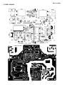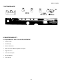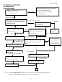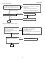
1
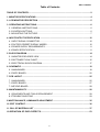
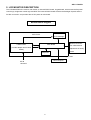
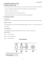
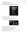
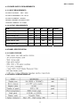
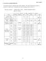
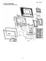
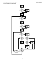
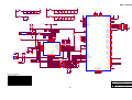
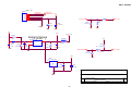
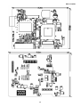
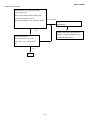
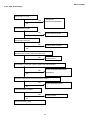
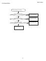
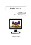
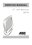
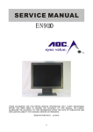
DELL E152FPc
SERVICE MANUAL
15” LCD MONITOR
DELL E152FPc
THESE DOCUMENTS ARE FOR REPAIR SERVICE INFORMATION ONLY. EVERY REASONABLE EFFORT
HAS BEEN MADE TO ENSURE THE ACCURACY OF THIS MANUAL; WE CANNOT GUARANTEE THE
ACCURACY OF THIS INFORMATION AFTER THE DATE OF PUBLICATION AND DISCLAIMS RE LIABILITY
FOR CHANGES, ERRORS OR OMISSIONS.
MANUFACTURE DATA: MAR.-20-2005
1
DELL E152FPc
Table of Contents
TABLE OF CONTENTS............................................................................................................... 2
1. MONITOR SPECIFICATIONS ................................................................................................. 4
2. LCD MONITOR DESCRIPTION .............................................................................................. 5
3. OPERATING INSTRUCTIONS ................................................................................................ 6
3.1 GENERAL INSTRUCTIONS............................................................................................... 6
3.2 CONTROL BUTTONS ........................................................................................................ 6
3.3 ADJUSTING THE PICTURE............................................................................................... 7
4. INPUT/OUTPUT SPECIFICATION ........................................................................................ 10
4.1 INPUT SIGNAL CONNECTOR......................................................................................... 10
4.2 FACTORY PRESET DISPLAY MODES............................................................................ 10
4.3 POWER SUPPLY REQUIREMENTS ............................................................................... 11
4.4 PANEL SPECIFICATION .................................................................................................. 11
5. BLOCK DIAGRAM ................................................................................................................ 14
5.1 MONITOR EXPLODED VIEW .......................................................................................... 14
5.2 SOFTWARE FLOW CHART............................................................................................. 15
5.3 ELECTRICAL BLOCK DIAGRAM..................................................................................... 17
6. SCHEMATIC .......................................................................................................................... 18
6.1 MAIN BOARD................................................................................................................... 18
6.2 PWPC BOARD ................................................................................................................. 22
7. PCB LAYOUT ........................................................................................................................ 25
7.1 MAIN BOARD................................................................................................................... 25
7.2 PWPC BOARD ................................................................................................................. 27
7.3 KEYPAD BOARD ............................................................................................................. 28
8. MAINTAINABILITY................................................................................................................ 28
8.1 EQUIPMENTS AND TOOLS REQUIREMENT ................................................................. 28
8.2 TROUBLE SHOOTING .................................................................................................... 29
9.WHITE-BALANCE, LUMINANCE ADJUSTMENT ................................................................. 35
10. EDIT CONTENT................................................................................................................... 36
11. BILL OF MATERIAL LIST ................................................................................................... 37
12.DEFINITION OF PIXEL DEFECTS....................................................................................... 53
2
DELL E152FPc
Revision List
Revision
Date
Revision History
A00
Mar-20-2005
Initial Release
A01
April-25-2006
Add” Max Brightness measurement” on
Page36
3
TPV model
DELL E152FPc
1. MONITOR SPECIFICATIONS
Driving system
TFT Color LCD
Size
38.1mm(15.0")
Pixel pitch
0.297mm(H) x 0.297mm(V)
Viewable angle
120˚ (H) 100˚ (V)
Response time (typ.)
25 ms
Video
Analog Only
Sync. Type
H/V TTL Separate and Composite Sync.
H-Frequency
30kHz – 63kHz
V-Frequency
56-76Hz
Flat Panel
Input
Display Colors
Over 16.2 million Colors
Dot Clock
80MHz
Max. Resolution
1024 x 768
Plug & Play
VESA DDC2BTM
ON Mode
<25W
<35W(For Samsung XH panel)
Power Consumption
OFF Mode
<1W
Maximum Screen Size
Horizontal : 11.9”(304.1mm)
Vertical:8.9”(228.1mm)
Power Source
110~240VAC,50~60Hz
Environmental
Operating Temp: 5°C to35°C
Considerations
Storage Temp.:-20°C to80°C
Packaged
5.31Kgs Unit
Unpackaged
3.50Kgs Unit
Weight (N. W.)
4
DELL E152FPc
2. LCD MONITOR DESCRIPTION
The LCD MONITOR will contain a main board, an internal PWPC board, keypad board, which house the flat panel
control logic, brightness control logic and DDC.The internal PWPC board will drive the backlight of panel and the
DC-DC conversion. and provides the 5V DC-power to main board.
Monitor Block Diagram
Flat Panel and
CCFL Drive.
CCFL backlight
RS232 Connector
Main Board
PWPC board
For white balance
(Include adapter and Inverter
adjustment in factory
board)
mode
Keyboard
Video signal, DDC
Host Computer
AC-IN
100-240V
5
DELL E152FPc
3. OPERATING INSTRUCTIONS
3.1 GENERAL INSTRUCTIONS
Press the power button to turn the monitor on or off. The other control buttons are located at front panel of the
monitor. By changing these settings, the picture can be adjusted to your personal preferences.
-The power cord should be connected.
-Connect the video cable from the monitor to the video card.
-Press the power button to turn on the monitor, the power indicator will light up.
3.2 CONTROL BUTTONS
-Power Button:
When pressed, the monitor enters the off mode, and the LED turns blank. Press again to restore normal status.
-Brightness Button:
The Brightness Button is used to select the Brightness/Contrast adjust functions. Press to switch functions or
adjust settings.
-Auto Adjust Key:
The Auto Adjust Key is used to automatically set the H Position, V Position, Clock and Phase.
-Power Indicator:
Green
— Power On mode.
Orange — Power Saving mode.
Blank
—Power Off Mode.
Control Buttons
A.Buttons for the OSD menu (On-Screen-display)
B. Brightness/Contrast menu Button
C. Auto Adjust Button
D. Power On/Off Button and indicator
6
DELL E152FPc
3.3 ADJUSTING THE PICTURE
To set the OSD menu, perform the following steps:
Briefly press the SELCT / MENU button to activate the OSD menu.
The main menu appears on the screen with icons for the setting functions.
The first symbol (Exit) is highlighted.
Necessary, press the- or + button to mark another icon (e.g. Positioning).
Press the SELECT/MENU button to select the highlighted icon.
The corresponding setting window (here: Positioning) is displayed.
The first symbol (Exit) is highlighted.
If necessary, press the – or + button to mark the desired icon.
Press the SELECT/MENU button to select the highlighted function.
Press the – or + button to adjust the value for the selected function.
Press the SELECT/MENU button to exit the function.
Press the SELECT/MENU button to exit the sub-menu when “Exit” function is highlighted;
All changes are stored automatically.
7
DELL E152FPc
Adjusting the brightness and contrast
Calling the Brightness / Contrast setting window using Brightness button.
Brightness
Setting the brightness of the display
With this function you change the brightness of the background lighting.
Contrast
Setting the contrast of the display
With this function you modify the contrast of bright colour tones.
Adjusting size and position
Calling the Positioning setting window
H-Position
Adjusting the horizontal position
With this function you move the picture to the left or to the right.
V-Position
Adjusting the vertical position
With this function you move the picture up or down.
Setting Image
Calling the Image setting window
Auto Adjust Auto adjust will produce best image automatically, The information of “ Auto Adjust In
Progress” will show;
Pixel clock
Adjusting the pixel clock
Phase
Adjusting the phase
Setting colour temperature and colours
Calling the Color setting window
Selecting the colour temperature
The colour temperature is measured in K (= Kelvin). You can select from Normal Preset,
Blue Preset, Red Preset to User Preset;
Normal preset
= Original colour of the LCD display, it’s 6500K;
Blue preset
=5700Kcolour of the LCD display, it’s 9300K;
Red preset
=9300K colour of the LCD display, it’s 5700K;
User preset
= Setting user-defined colours
In the user preset setting you can change the colour ratios of the basic colours (red,
green, blue) as required.
Setting display of the OSD menu
Calling the OSD Set up setting window
Horizontal
Setting the horizontal position of the OSD menu
Position
With this function you move the OSD menu to the left or to the right.
8
DELL E152FPc
Vertical
Setting the vertical position of the OSD menu
Position
With this function you move the OSD menu up or down.
OSD
Setting the display duration of the OSD menu, the default value is 20s;
Hold Time
With this function you select a value from 0 to 60 seconds.
If the set time expires without a setting being made, the OSD menu is automatically faded
out.
OSD
Setting the display of the OSD menu lock or unlock.
Lock
With this function you select Yes to lock OSD, NO to unlock it.
Setting Language
Calling the Language setting window
With this function you choose between English (default setting), French, German,
Spanish and Japanese as the language for the OSD menu.
Factory Reset
Activating the factory settings
With this function all settings except Language of OSD are reset to the factory settings
without prompting for confirmation.
9
DELL E152FPc
4. INPUT/OUTPUT SPECIFICATION
4.1 INPUT SIGNAL CONNECTOR
15-pin D-sub connector
PIN NO.
DESCRIPTION
PI N NO.
DESCRIPTION
1.
Red
9.
+5V
2.
Green
10.
Detect Cable
3.
Blue
11.
Ground
4.
Ground
12.
DDC-Serial Data
5.
Ground
13.
H-Sync
6.
R-Ground
14.
V-Sync
7.
G-Ground
15.
DDC-Serial Clock
8.
B-Ground
VGA Connector layout
1
5
6
10
11
15
4.2 FACTORY PRESET DISPLAY MODES
Sync Polarity
Horizontal
Display Mode
Frequency (kHz)
Vertical
Frequency (Hz)
Pixel Clock
(MHz)
(Horizontal /
Vertical)
DOS 720 x 400
31.5
70.1
28.3
-/+
VGA 640 x 480
31.5
60.0
25.18
-/-
37.5
75.0
31.5
-/-
VESA 800 x 600
37.9
60.3
40.0
+/+
VESA 800 x 600
46.9
75.0
49.5
+/+
VESA 1024 x 768
48.4
60.0
65.0
-/-
VESA 1024 x 768
60.0
75.0
78.8
+/+
VESA
640
x
480
For ergonomic reasons, a screen resolution of 1024 x 768 pixels is recommended. Because of the technology used
(active matrix) an LCD monitor provides a totally flicker-free picture even with a refresh rate of 60 Hz.
10
DELL E152FPc
4.3 POWER SUPPLY REQUIREMENTS
4.3.1 INPUT REQUIREMENTS
AC INPUT VOLTAGE: 100V ~ 240V
AC INPUT FREQUENCY: 50 ~ 60 HZ
AC INPUT CURRENT: 1.5A MAX
INRUSH CURRENT: 50A MAX AT 220V
LEAKAGE CURRENT: 3.5 mA Max.
4.3.2 OUTPUT REQUIREMENTS
ITEM
MIN.
TYP.
MAX.
UNIT
Output voltage (12V)
11.4
12
12.6
V
Output current (12V)
0
1.5
2.0
A
Output voltage ( 5V)
4.75
5.0
5.25
V
Output current (5V)
0
1.5
2.0
A
Ripple & Noise (12V)
200
mV
Ripple & Noise (5V)
100
mV
4.4 PANEL SPECIFICATION
4.4.1 PANEL FEATURE
4.4.2 DISPLAY CHARACTERISTICS
11
REMARK
DELL E152FPc
4.4.3 OPTICAL CHARACTERISTICS
12
DELL E152FPc
4.4.4 PARAMETER GUIDE LINE FOR CCFL INVERTER
BACKLIGHT
13
DELL E152FPc
5. BLOCK DIAGRAM
5.1 MONITOR EXPLODED VIEW
14
DELL E152FPc
5.2 SOFTWARE FLOW CHART
1
Y
2
3
N
4
N
5
Y
6
N
7
8
Y
9
N
10
11
Y
N
12
Y
14
13
Y
15
Y
17
18
N
19
Y
15
N
N
16
DELL E152FPc
1) MCU Initializes.
2) Is the EEprom blank?
3) Program the EEprom by default values.
4) Get the PWM value of brightness from EEprom.
5) Is the power key pressed?
6) Clear all global flags.
7) Are the AUTO and SELECT keys pressed?
8) Enter factory mode.
9) Save the power key status into EEprom.
Turn on the LED and set it to green color.
Scalar initializes.
10) In standby mode?
11) Update the lifetime of back light.
12) Check the analog port, are there any signals coming?
13) Does the scalar send out an interrupt request?
14) Wake up the scalar.
15) Are there any signals coming from analog port?
16) Display "No connection Check Signal Cable" message. And go into standby mode after the message
disappears.
17) Program the scalar to be able to show the coming mode.
18) Process the OSD display.
19) Read the keyboard. Is the power key pressed?
16
DELL E152FPc
5.3 ELECTRICAL BLOCK DIAGRAM
Main Board
12MHz Crystal
LCD Interface
(X200)
(CN201)
TCLK/XTAL
LVDS Signal output
Scalar GmZan3
MCU
(Include MCU, ADC, OSD)
MTV312MV
(U200)
(U202)
H-sync, V-sync
R/G/B
EPR_SDA
EPR_SCL
OSD
Control
EEPROM
D-Sub
Interface
M24C16
Connector
(CN301)
(U201)
(CN100)
DB12_SDA,
DB15_SCL
EEPROM
24C02
(U100)
17
DELL E152FPc
6. SCHEMATIC
6.1 MAIN BOARD
+5V
1
2
+5V
VGA_5V
D100
BAT54C
3
DDC_5V
C101
0.1uF/16V
VGA_5V
C104
0.1uF/16V
D101
BAV99
ZD101
LL5232B 5.6V 5%
D102
BAV99
GND
D103
BAV99
FB101 0 1/16W
U100
1
2
3
4
A0
A1
A2
GND
VCC
WP
SCL
SDA
8
7
6
5
R105
47K 1/16W
GND
CN100
11
RXD
DDC_SDA_A1
R109 47 1/16W
DDC_SCL_A1
DDC_SDA_A1
17
R104
47K 1/16W
GND
12
HSYNC
13
VSYNC
14
M24C02WMN6
GND
R110 47 1/16W
ZD102
DDC_SCL_A1
15
VGA
16
ZD103
GND
1
6
2
7
3
8
4
9
5
10
GND
C103
0.01uF
RED+
C105
0.01uF
RED-
RED+
RED-
100 1/16W
GIN
BIN
0 1/16W
FB100
TXD
R108
R107
75 1/16W
C107
0.01uF GREEN+
C108
0.01uF
GREEN+
GREEN-
100 1/16W
75-ohm terminating
resistor very close to
the VGA conn.
GND
R106
100 1/16W
GND
LL5232B 5.6V 5%
LL5232B 5.6V 5%
R103
R102
75 1/16W
RIN
R101
100 1/16W
C109
NC
R123
NC
SOG_MCSS
GND
FB102 0 1/16W
GND
Pins 6/7/8 are R/G/B
return lines resp.
R112
75 1/16W
+5V
DDC_SDA_A1
R116
NC
DDC_SCL_A1
R100
NC
DDC_SDA
DDC_SCL
R111
100 1/16W
GND
C100
0.01uF BLUE+
C111
0.01uF BLUE-
BLUE+
BLUE-
R113
100 1/16W
P.2
+5V
R114
4.7K 1/16W
P.2
GND
R115
VGA_PG
R130
100 1/16W
Q101
2N7002E
R125
0 1/16W
ZD104
LL5232B 5.6V 5%
R127
R118 100 1/16W
TXD
R126
NC
SHEET2
UART_DI
GND
0 1/16W
R133
0 1/16W
R124
0 1/16W
100 1/16W
R129
R119
100 1/16W
RXD
ZD106
LL5232B 5.6V 5%//NC
C102
NC
SHEET2
UART_DO
R128
NC
NC
VS-IN
Q102
2N7002E
R131
GND
R132
0 1/16W
R117
VSYNC
NC
0 1/16W
R120
HSYNC
ZD107
LL5232B 5.6V 5%//NC
GND
HS-IN
100 1/16W
R121
ZD105 2.2K 1/16W
LL5232B 5.6V 5%
ZD100
LL5232B 5.6V 5%
R122
2.2K 1/16W
C106
NC
GND
GND
GND
GND
GND
AOC
Title
Size
1. TO SUPPORT SOG -->ADD R123 1M OHM
ZAN3 LCD Control Board
Document Number
Rev
Analog Input
Date:
18
星期五, 十月 03, 2003
H
Sheet
1
of
4
DELL E152FPc
+3.3V
3.3V_DVDD
+1.8V
0.1uF/16V
3.3V_AVDD
U200
0.1uF/16V
C219
10uF/16V
0.1uF/16V
C209
+
0.1uF/16V
C200
FB203
120 OHM
0.1uF/16V
C223
8/22 del C218 for DIP
C220
C216
22uF/16V
0.1uF/16V
C222
+
0.1uF/16V
C221
0.1uF/16V
C217
FB202
120 OHM
87
91
96
100
109
1.8V_AVDD
GND
106
104
GND
AVDD_BLUE_3.3
AVDD_GREEN_3.3
AVDD_RED_3.3
AVDD_ADC_3.3
AVDD_RPLL_3.3
20
35
49
81
114
3.3V_AVDD
CVDD_1.8
CVDD_1.8
CVDD_1.8
CVDD_1.8
CVDD_1.8
GND
1.8V_AVDD
1.8V_DVDD
22
41
61
75
112
3.3V_DVDD
RVDD_3.3
RVDD_3.3
RVDD_3.3
RVDD_3.3
RVDD_3.3
0.1uF/16V
C208
0.1uF/16V
C207
0.1uF/16V
C206
C201
10uF/16V
0.1uF/16V
C205
+
0.1uF/16V
C204
C202
FB201
120 OHM
Close to respective power Pins
GND
0.1uF/16V
C203
0.1uF/16V
C210
22uF/16V
0.1uF/16V
C215
+
0.1uF/16V
C214
FB200
120 OHM
0.1uF/16V
C213
C211
0.1uF/16V
C212
1.8V_DVDD
3.3V_DVDD
AVDD_3.3
AVDD_3.3
AVDD_3.3
AVSS
AVSS
AVSS
VDD_RPLL_1.8
VDD_ADC_1.8
3.3V_AVDD
4
17
19
5
16
18
CN201
+5V
+3.3V +5V
NC
R224
HS-IN
C225
22uF/16V
WP
+
C226
0.1uF/16V
MEM_REG
111
+5V
GND
GND
R216
NC
X200
+5V
+5V
C230
22pF
C0603
12MHz
C231
22pF
C0603
C234
GND
4.7K 1/16W
4.7K 1/16W
4.7K 1/16W
4.7K 1/16W
R221
R212
R213
R214
4.7K 1/16W
4.7K 1/16W
4.7K 1/16W
R233
39
38
37
36
35
34
33
32
31
30
29
R220
DA8/P7.1
DA9/P7.2
HBLANK/P4.1
VBLANK/P4.0
DA7/HCLAMP
DA6/P5.6/CKO
P6.7/DA13
P6.6/DA12
P6.5/DA11
P6.4/DA10
HSCL/P3.0/RXD
R232
44
43
42
41
40
VSYNC/P7.4
HSYNC/P7.3
DA3/P5.3
DA4/P5.4
DA5/P5.5
HSCL2/P7.5
HSDA2/P7.6
VDD3
DA0/P5.0
DA1/P5.1
DA2/P5.2
RST
VDD
P6.3/AD3
VSS
X2
X1
ISDA/P3.4/T0
ISCL/P3.5/T1
STOUT/P4.2
P6.2/AD2/HLFH1
P1.0
85
86
92
HS-IN
VS-IN
SOG_MCSS
101
116
2
MUTE
STBY
WP
LED-ORG
LED-GRN
KEY_ON/OFF
KEY_RIGHT
RST#
R218
10K 1/16W
121
122
123
124
125
126
127
128
KEY_AUTO
UART_DI
R225
100 1/16W
KEY_MANU
KEY_AUTO
R226 100 1/16W
RP200
100 1/16W
5
4
6
3
7
2
8
1
5
6
7
8
RP201
+5V
R227
NC
GPIO10
GPIO11
RESERVED
RESERVED
RESERVED
RESERVED
RESERVED
RESERVED
RESET_OUT
RESETn
GPIO8
GPIO9
RESERVED
RESERVED
RESERVED
RESERVED
RESERVED
RESERVED
GPIO5/AD7
GPIO6/AD6
GPIO7/AD5
HFS/AD4
HDATA3/AD3
HDATA2/AD2/OSC_SEL
HDATA1/AD1/HP1
HDATA0/AD0/HP0
GPIO2
GPIO1/PWM1
GPIO0/PWM0
WRn
RDn
HCLK/ALE
MEM_REG
119
120
118
117
DEN
DHS
DVS
DCLK
WRn
RDn
HCLK/ALE
GPIO4/MEM_REG
PPWR
PBIAS
R228
NC
4
3
2
1
100 1/16W
VBUFS_RPLL
VCO_LV
R2314.7K 1/16W
KEY_MANU
UART_DO
GPIO3/IRQn
VGA_PG
R2304.7K 1/16W
GND
KEY_LEFT
GPIO12
GPIO13
RESERVED
RESERVED
RESERVED
RESERVED
RESERVED
RESERVED
ADC_TEST
0 1/16W
R223
100 1/16W
KEY_LEFT
HSYNC
VSYNC
SOG_MCSS
R217
1
2
3
4
NC
1
RESERVED
RESERVED
RESERVED
RESERVED
RESERVED
RESERVED
RESERVED
RESERVED
RED+
REDGREEN+
GREENBLUE+
BLUE-
LED-ORANGE
LED-GREEN
KEY_ON/OFF
KEY_RIGHT
18
19
20
21
22
23
24
25
26
27
28
GND
R219
10K 1/16W
7
8
9
10
11
12
13
14
15
16
17
R2294.7K 1/16W
G-PROBE
NC
GND
CN200
C229
P1.1
P3.2/INT0
P1.2
P1.3
P1.4
P1.5
P1.6
P1.7
P6.1/AD1
P6.0/AD0
HSDA/P3.1/TXD
C233
22 ohm 1/16w
U202
MTV312MV
0.1uF/16V
C228
0.1uF/16V
GND
6
5
4
3
2
1
+5V
97
98
93
94
88
89
RED+
REDGREEN+
GREENBLUE+
BLUE-
GND
DDC_SDA
DDC_SCL
TCLK
TCLK
R211
NC
GND
DDC_SDA
DDC_SCL
CH0P_LV
CH0N_LV
RESERVED
RESERVED
RESERVED
RESERVED
RESERVED
RESERVED
XTAL
CRVSS
CRVSS
CRVSS
CRVSS
CRVSS
CRVSS
CRVSS
CRVSS
CRVSS
CRVSS
R200
NC
NC
NC
100 1/16W
100 1/16W
100 1/16W
R205
R206
R207
110
RDn
VS-IN
R236
6
7
8
9
10
11
12
13
TX3+O
TX3-O
TXCK+O
TXCK-O
TX2+O
TX2-O
TX1+O
TX1-O
14
15
24
25
26
27
28
29
TX0+O
TX0-O
20
18
16
14
12
10
8
6
4
2
STI_TM1
STI_TM2
19
17
15
13
11
9
7
5
3
1
PANEL_PWR
PITCH 2.0mm
GND
30
31
32
33
34
37
38
39
40
43
44
45
46
47
48
51
52
53
54
55
56
57
58
59
60
63
64
65
66
67
68
69
78
79
80
BKLT_PWM
BKLT_PWM
70
71
72
73
PANEL_EN
BKLT_EN
74
77
PANEL_EN
BKLT_EN
107
3
83
84
GND
21
23
36
42
50
62
76
82
113
115
M24C16-MN6T
GND
RST#
R210 100 1/16W
GND
CH3P_LV
CH3N_LV
CHKP_LV
CHKN_LV
CH2P_LV
CH2N_LV
CH1P_LV
CH1N_LV
NC
R209
8
7
6
5
GND
GND_ADC
AGND_ADC
AGND_BLUE
AGND_GREEN
AGND_RED
VSS_RPLL
AVSS_RPLL
GND
R235
R208 100 1/16W
VCC
TEST
SCL
SDA
4.7K 1/16W
A0
A1
A2
GND
R204
U201
4.7K 1/16W
NC
C224
0.1uF/16V
1
2
3
4
R222
R202
0 1/16W
R203
R201
103
102
90
95
99
105
108
NC
BLON/OFF
GMZAN3-L
GMZAN3-L
GND
GND
BOOTSTRAP OPTIONS
HDATA1
HDATA0
LOW
LOW
N/A
LOW
HIGH
Reserved
HIGH
LOW
2-wire I/F
HIGH
HIGH
6-wire Genesis I/F
AOC
OSC_SEL (HDATA2)
LOW
EXTERNAL OSC.
HIGH
XTAL and INTERNAL OSC
Title
ZAN3 LCD Control Board
Size
Document Number
Date:
星期五, 十月 03, 2003
Rev
ZAN3
When X2 is used to drive ZAN3 (the optional X1 crystal is not used)
remove the shunt from JP1.
19
H
Sheet
2
of
4
DELL E152FPc
R310
4.7K 1/16W
LED-GREEN
+5V
3
Q302
PMBS3904 R311
1
4.7K 1/16W
LED-ORANGE
2
3
Q301
PMBS3904
1
4
3
2
1
RP301
4.7K 1/16W
+5V
2
5
6
7
8
R301 4.7K 1/16W
+5V
RP300 100 1/16W
1
8
2
7
3
6
4
5
8
7
6
5
4
3
2
1
5
6
7
8
5
6
100 1/16W
8
R304
7
KEY_AUTO
KEY_MANU
KEY_RIGHT
KEY_LEFT
KEY_ON/OFF
CN301
GRNLED
ORGLED
AUTO
ENTER
RIGHT
LEFT
POWER
CP301
CP300
0.001uF
GND
4
3
2
1
4
3
2
1
0.001uF
GND
LCD_+3.3V
PANEL_PWR
2
Q300
AO3401
3
R306
R308
1
PANEL_EN
C300
0.1uF/16V
3
10K 1/16W
2
GND
R307
+
C301
22uF/16V
C302
0.1uF/16V
10K 1/16W
3D
Q303
PMBS3904
1K 1/16W
1
1
G
AO3401
2
S
GND
GND
AOC
Title
Size
ZAN3 LCD Control Board
Document Number
Rev
keyboard&panel power
Date:
20
星期五, 十月 03, 2003
Sheet
H
3
of
4
DELL E152FPc
CN400
1pin = 1A
BLON/OFF
BRIGHTNESS
1
2
3
4
5
6
BLON/OFF
BRIGHTNESS
+5V
BLON/OFF
C408
2.2uF/16V
C403
0.1uF/16V
+ C402
BKLT_EN
R400 4.7K 1/16W
R403
NC
+
47uF/16V
GND
GND
GND
GND
GND
+5V
+3.3V
LCD_+3.3V
FB402
TO252/TO263
U402
NC
Two types ノ
D401
AIC1084-33M
3
VIN
VOUT
SR24
C417
C404
NC
47uF/16V
1
+
ADJ
120 OHM
+5V
2
FB401
C409
+
C410
R404
C406
0.1uF/16V
1K 1/16W
0.1uF/16V
100uF/16V
GND
BRIGHTNESS
BKLT_PWM
GND
C411
2.2uF/16V
R405
1K 1/16W
+
+1.8V
GND
U401
GND
AIC1117A-18CY
3
VI
VO
2
C415
C416
+
0.1uF/16V
1
100uF/16V
AOC
GND
Title
Size
ZAN3 LCD Control Board
Document Number
Rev
H
Board Power Supply
Date:
21
星期五, 十月 03, 2003
Sheet
4
of
4
DELL E152FPc
6.2 PWPC BOARD
Q203 SI4431 OR AO4411
TP1
L201 150UH
L205
1
2
3
4
JUMP
Q202
C202
+ C201
Q201
8
7
6
5
150U/25V
R212
3.9K
1000P
PT201
0.18U/160V
2
6
2SC5706
Q207
SST3906
3.9K
R208
4.7K
1
7
80AL15T-7-YS
R222 15K
1
2
R232
1K
D205 RLS4148
1
Q210
R218 470
L203
2
4
3
1
D209
C209
4.7U/16V
R205
68K
C205
HVL
33L8021-2D
R214
L206
JUMP
CON203
TP3
9
TP4 OPEN
HVL
1
3,4
1
3
Q205
SST3904
R210
12K
5
C213
Q209
R220 12K
D201
SMAL240 OR SR24
0.1U/25V
R202
5.1K
33L8021-2D
C227
C211
1U/25V
NO/OFF
2
R226 R227
1K
1K
D203
11B
R216
220
C204
R207
OPEN
C207
R224 R225
1K
1K
C230
DTC144WKA
1
OPEN
DTA144WKA
0.1U/25V
CON201
1
+12V
C226
1
HVO
2
4A/63V
3
F201
RLS4148
73L174-30-YS
2SC5706
C224
2
1U/25V
R234 620
OPEN
D207
R240
RLS4148
0.1U/25V
C221
C219
51K
R238
8
7
6
5
C231
R213
3.9K
150U/25V
C212
1U/25V
1000P
33L8021-2D
CON204
1
OPEN
0.18U/160V
1
HVL
2
6
2
1
3
R223 15K
R211
12K
2
TP6
1
7
33L8021-2D
R233
1K
80AL15T-7-YS
C203
1U/25V
OPEN
9
3,4
Q208
SST3906
3.9K
PT202
3
R203
5.1K
1
HVO
C229
2SC5706
R215
1
TP2
5
Q211
Q206
SST3904
R209
4.7K
CON202
C216
D202
R221 12K
SMAL240 OR SR24
1U/25V
R206
68K
R230 R231
1K
1K
D204
11B
R217
220
C210
TP5 HVL
C228
R228 R229
1K
1K
2
1
2
3
4
5
6
7
8
+ C223
R236
510
1
16
15
14
13
12
11
10
9
1
2
3
4
1U/25V
L202 150UH
C208
330P/50V
R204
10K
12K
0.47U/25V
Q204 SI4431 OR AO4411
CT
REF
RT
SCP
1IN+ 2IN+
1IN2IN1FBK 2FBK
1DTC 2DTC
1OUT 2OUT
GND
Vcc
TL1451ACDR
U201
DIM
R201
24K
R219
D206 RLS4148
1
L204
4
Q212
470
1
C206
D210
RLS4148
2SC5706
2
3
73L-174-30-YS
2
0.1U/25V
R235 620
D208
R241
AOC (Top Victory) Electronics Co., Ltd.
C222
is power GND
0.47U/25V
2. FOR 17"&15" 4 LAMPS INVERTER
Size
Document Number
Date:
Tuesday, June 01, 2004
Sheet
2
of
OPEN
R237 510
12K
1U/25V
Rev
A
PWPC1742CPD1(715L-1283-1)
C220
R239
Title
C225
RLS4148
51K
is signal GND
2
22
DELL E152FPc
C0N102
GND
GND
5V
5V
GND
GND
12V
12V
DIM
GND
ON/OFF
GND
12
11
10
9
8
7
6
5
4
3
2
1
5V
12V
DIM
ON/OFF
GND
R920
47 1/2W
33A8009-12G-H
C920
0.001uF/500V
T901
D910
4
1
O
+
DB901
2KBP06M
1
R906
1M 1/4W
3
+
R904
1M 1/4W
C905
0.0015uF/2KV
9
L903
+ C922
1000uF/16V
R903
100K 2W
R921
47 1/2W
C904
120uF/400V
12V
20A/100V
+
C924
470uF/16V
C930
1000P
O 7,8
ZD904
SML4736
D901
-
R907
1M 1/4W
R905
1M 1/4W
0.001uF/500V
UF4007
L904
7,8
3
5
L902
73L-174-26-T
1
+
C907
0.1uF
4
C906
22uF
D902
PS102R
R908
5.1 1/4W
5V
D911
10A/100V
2
3
2
C926
0.1uF
C921
+ C923
1000uF/16V
+
C925
470uF/16V
10,11
C927
0.1uF
C931
1000P
4O
7
8
5
6
1
R914
24K 1/4W
4
SG6841
2
IC901
SG6841
3
C903 0.47uF/250V
R915
10 1/4W
Q903
FQPF7N80C,STP8NK80ZFP
C912
0.0047uF/250V
R929
100 1/4W
FB901
BEAD
C911
N.C 1/6W
R916
10K 1/4W
R913
10K 1/4W
4
NR901
NTCR
IC902
PC123FY82 4P
R909
4.7K 1/4W
3
t
ZD903
HZ5C1
R928
1K 1/4W
R925
1K 1/4W
D903
1N4148
F901
FUSE
C901
C902
0.001uF/250V 0.001uF/250V
ZD902
HZ12B2
R917
0.39 2W
C910
0.001uF
1
R902
1M 1/4W
2
R901
1M 1/4W
ZD901
MTEJ20B
R912
100 1/4W
C908
0.1uF
R910
4.7K 1/4W
C929
0.1uF
R922
33K 1/4W
R927
0 1/4W
R923
3.6K 1/4W
R926
1K 1/4W
Q901
2PA733P
IC903
HTL431
3
Q902
2PC945P
2
C909
0.1uF
C928
0.01uF
R911
4.7K 1/4W
R924
2.4K 1/4W
1
CN901
AOC (Top Victory) Electronics Co., Ltd.
Title
23
1.POWER 12V&5V OUTPUT
Size
Document Number
Date:
Tuesday, June 01, 2004
Rev
PWPC1742CPD1(715L-1283-1)
Sheet
A
2
of
2
DELL E152FPc
7. PCB LAYOUT
7.1 MAIN BOARD
25
DELL E152FPc
26
DELL E152FPc
7.2 PWPC BOARD
27
DELL E152FPc
7.3 KEYPAD BOARD
8. MAINTAINABILITY
8.1 EQUIPMENTS AND TOOLS REQUIREMENT
Voltage meter.
Oscilloscope.
Pattern Generator.
DDC Tool with a IBM Compatible Computer.
Alignment Tool.
LCD Color Analyzer.
Service Manual.
User Manual.
28
DELL E152FPc
8.2 TROUBLE SHOOTING
8.2.1 MAIN BOARD
1.NO SCREEN APPEAR
Check Power board, is there DC level output?
Check Correspondent component.
Measured U402 pin 3 = 5 V?
No DC Level
Measured U402 pin 2= 3.3V?
Is there any shortage or cold solder?
Measured U401pin 2 =1.8V?
Check Power Board.
Yes, all DC level exist
Disconnected the Signal cable (Loose the
Yes. there have OSD show
Led Green
Signal cable), Is the screen show Block
Connected the Signal cable again,
WRGB color bars?
Check LED status.
No, nothing is show
Connected the Signal cable again,
Led Orange
Check LED status.
Check Power switch is in Power-on
Replace U200
status, and check if Power switch
Scalar IC
Led orange
had been stuck?
Led Green
Check the Wire-Harness from CN301
OK, Keyboard no stuck
Check Correspondent
Measured RGB (R116, R106, R111) H, V
OK, Wire tight enough
component short/open
Input at U200 pin 85,86, was there have
(Protection Diode)
NG
signal?
and Signal cable bad ?
Check Panel-Power Circuit Block
OK, Panel Power OK
Check U200 Data-output Block
OK, input Normal
OK, U200 data OK
Measured Crystal X200 (12.00MHz)
Replace Inverter board and Check
OK, clock normal
Inverter control relative circuit
Replace U200 (GMZan3)
Re-do White balance adjust
OK
Note: 1. If Replace “MAIN-BOARD”, Please re-do “DDC-content” programmed & “WHITE-Balance”.
2. If Replace “Inverter Board” only, Please re-do “ WHITE-Balance”
29
DELL E152FPc
2.PANEL-POWER CIRCUIT
NG
Check FB401 should have response from 0V to 3.3V
Check the PPWR panel power relative circuit,
Q300, Q303 In normal operation, when LED =green,
When we switch the power switch from on to off
R308 should =0 v,
If PPWR no-response when the power switch
Turn on and turn off, replace the U200-GMZan3
OK, FB401 have response
NG, no Voltage
Check U202 pin 74,77,80=3.3V
Measured the Q300 pin 2= 3.3 V?
Yes
OK
Replace Q300 ( N-mos, AO3401)
OK
3. INVERTER CONTROL RELATIVE CIRCUIT
Measured the inverter connector CN400
Check the Bklt-On relative circuit, R400,
NG
Pin1 on/off control=3.3V (on)
In normal operation, when LED =green,
Pin2 PWM signal control dim 0V-5V when
R400 Bklt-On should =3.3 v,
adjust the brightness
If Bklt-On no-response when the power switch turn on-off,
Replace U202 GmZAN3
NG, still no screen
Replace Inverter board to new-one,
NG
Check NO SCREEN APPEAR block
and Check the screen is normal??
OK
OK
30
DELL E152FPc
4.U200-DATA OUTPUT
Measured DVS, DHS (pin 8,9 from U200)
Is the waveform ok?
DCLK around 48 MHZ, DVS=60.09Hz, DHS
around 31 KHz? (Refer to input
NG, no transition
signal=640x480@60 Hz 31k, and LED is Green)
Replace GMZan3 (U200) or replace
MAINBOARD.
OK
If Main Board being replaced please do
the DDC – content reprogrammed and
Check U200 GMZan3
re-adjust the white balance
Signal output TX1+, TX1-, TX2+,
TX2-, TX3+, TX3-, Is the waveform
ok?
OK
OK
31
DELL E152FPc
8.2.2 PWPC BOARD
1.) No power
Check to CN102 Pin10 = 5V
OK
Check Interface board
NG
Check AC line volt 120V or
220V
NG
Change F901
OK
Check the voltage of C904(+)
NG
Check bridge rectified circuit
OK
Check start voltage for the pin3 of IC901
NG
Change IC901
Repeating the start voltage
Check the auxiliary voltage is smaller than 20V
NG
1) Check IC902, IC903,Q903
2) Check Q901, Q902…OVP circuit
OK
Check R919, D910,D911,D912,D913, ZD904
32
DELL E152FPc
2.) W / LED, No Backlight
Check C201 (+) =12V
NG
Change F201
Check D201/Q206/Q207
OK
Check ON/OFF signal
NG
Check Interface board
OK
Check U201 pin9=12V
NG
Change Q201 or Q202
OK
Check the pin1 of U201 have saw tooth wave
NG
Change U201
OK
Check D201 (-) have the output of square wave at short time.
Check Q205/Q207/D201/Q203
NG
Q206/Q204
OK
Check the resonant wave of pin2 & pin5 for PT201
NG
Check Q206/Q207/C210
OK
Check the output of PT201
NG
Change PT201
OK
Check connecter & lamp
33
DELL E152FPc
8.2.3 Keypad Board
OSD is unstable or not working
N
Is Keypad Board connecting normally?
Connect Keypad Board
Y
N
Replace Button Switch
N
Replace Keypad Board
Is Button Switch normally?
Y
Is Keypad Board Normally?
Y
Check Main Board
34
DELL E152FPc
9.WHITE-BALANCE, LUMINANCE ADJUSTMENT
Before started adjust white balance, please setting the Chroma-7120 MEM. Channel 3 to 65000K colors, MEM. Channel 4
to 93000K colors, MEM. Channel 9 to 57000K (our 9300 parameter is x = 283 ±28, y = 297 ±28, Y = 175±20 cd/m2, 6500
parameter is x = 313 ±28, y = 329 ±28, Y = 180 ±20 cd/m2, and 5700 parameter is x = 328 ±28, y = 344 ±28, Y = 180 ±20
cd/m2)
How to setting MEM.channel you can reference to chroma 7120 user guide or simple use “ SC” key and “ NEXT” key to
modify xyY value and use “ID” key to modify the TEXT description Following is the procedure to do white-balance adjust
Press MENU and AUTO-ADJUST button during press Power button will activate the factory mode,
Gain adjustment:
Move cursor to “-Factory Setting-” and press MENU key to enter this sub-menu;
Move cursor to “ Factory” and press MENU key;
Move cursor to “ Auto Level” and press MENU key to adjust Gain and Offset automatically;
a. Adjust sRGB (65000K) color-temperature
1. Switch the chroma-7120 to RGB-mode (with press “MODE” button)
2. Switch the MEM.channel to Channel 3 (with up or down arrow on chroma 7120)
3. The LCD-indicator on chroma 7120 will show x = 313 ±28, y = 329 ±28, Y = 180 ±20 cd/m2
4. Adjust the RED on OSD window until chroma 7120 indicator reached the value R=100
5. Adjust the GREEN on OSD, until chroma 7120 indicator reached G=100
6. Adjust the BLUE on OSD, until chroma 7120 indicator reached B=100
7. repeat above procedure (item 5,6,7) until chroma 7120 RGB value meet the tolerance =100±2
b. Adjust Color1 (93000K) color-temperature
8. Switch the chroma-7120 to RGB-mode (with press “MODE” button)
9. Switch the MEM.channel to Channel 4 (with up or down arrow on chroma 7120)
10. The LCD-indicator on chroma 7120 will show x = 283 ±28, y = 297 ±28, Y = 175 ±20 cd/m2
11. Adjust the RED on OSD window until chroma 7120 indicator reached the value R=100
12. Adjust the GREEN on OSD, until chroma 7120 indicator reached G=100
13. Adjust the BLUE on OSD, until chroma 7120 indicator reached B=100
14.Repeat above procedure (item 5,6,7) until chroma 7120 RGB value meet the tolerance =100±2
c. Adjust Color2 (57000K) color-temperature
15. Switch the chroma-7120 to RGB-mode (with press “MODE” button)
16. Switch the MEM.channel to Channel 9 (with up or down arrow on chroma 7120)
17. The LCD-indicator on chroma 7120 will show x = 328 ±28, y = 344 ±28, Y = 180 ±20cd/m2
18. Adjust the RED on OSD window until chroma 7120 indicator reached the value R=100
19. Adjust the GREEN on OSD, until chroma 7120 indicator reached G=100
20. Adjust the BLUE on OSD, until chroma 7120 indicator reached B=100
21. Repeat above procedure (item 5,6,7) until chroma 7120 RGB value meet the tolerance 100±2
22. Move cursor to “ Exit/Save” sub-menu and press MENU key to save adjust value and exit.
Turn the POWER-button off to on to quit from factory mode. Turn the POWER-button off to on to quit from
factory mode.
35
DELL E152FPc
Max Brightness measurement:
a. Switch to the full white pattern, in user mode main menu:
1. Set <Color Settings> Red, Green, and Blue to the max.
2. Set <Brightness> Brightness, Contrast to the max.
b. The Minimum brightness is 200cd/m2 ±20.
10. EDIT CONTENT
D-SUB Connector (Analog)
00
01
02
03
04
05
06
07
08
09
10
11
12
13
14
15
00:
00
FF
FF
FF
FF
FF
FF
00
10
AC
09
A0
44
43
42
41
16:
32
0D
01
03
68
1E
17
78
2E
B0
30
A1
58
4F
95
26
32:
1C
50
54
AF
CE
00
01
01
01
01
01
01
01
01
01
01
48:
01
01
01
01
01
01
64
19
00
40
41
00
26
30
18
88
64:
36
00
30
E4
10
00
00
18
00
00
00
FF
00
36
34
31
80:
38
30
33
39
39
41
42
43
44
0A
00
00
00
FD
00
38
96:
4C
1E
3F
08
00
0A
20
20
20
20
20
20
00
00
00
FC
112:
00
44
45
4C
4C
20
45
31
35
32
46
50
0A
20
00
36
36
DELL E152FPc
11. BILL OF MATERIAL LIST
CBPC560KSLDLN
CONVERSION BOARD FOR DL
M
1
PCS
KEPC560KDE1
KEY BOARD FOR T560K*DEL
M
1
PCS
PWPC1542SED1
POWER BOARD
M
1
PCS
11G6036 1
SPACER SUPPORT SCC-24
P
1
PCS
15G5996 1
REAR COVER
P
1
PCS
23L3178700 1A
LOGO
P
1
PCS
26L 800700 4A6444
BARCODE
P
1
PCS
33L4669 GV C
POWER BUTTON
P
1
PCS
33L4670 GV T
KEY PAD
P
1
PCS
34L1228AY2 2T
BEZEL
P
1
PCS
34L1229 Y2 2T
REAR COVER
P
1
PCS
40L 150700 1D
ID LABEL
P
1
PCS
40L 581700 3A
CARTON LABEL
P
1
PCS
41L7800700 1B
QSG
P
1
PCS
44L3231 12 A
EVA WASHER
P
2
PCS
44L3535700 1B
CARTON
P
1
PCS
44L3574 1
EPS(L R)
P
1
PCS
44L3574 2
EPS (L R)
P
1
PCS
45L 88607DE3
PE BAG
P
1
PCS
52L
1186
SMALL TAPE
P
8
CM
52L
1207 A
ALUMINIUM TAPE
P
2
PCS
52L6020 2DE5
Protect film
P
1
PCS
52L6025 11629
INSULATION PLATE
P
1
PCS
52L6025 11659
MYLAR
P
1
PCS
52L6025 11660
MYLAR
P
1
PCS
70L1500700 1B
cd manual
P
1
PCS
85L 649 1
SHIELD
P
1
PCS
89L1738GAA 10
SIGNAL CABLE
P
1
PCS
89L401A18NISA
SP 18C+IS14
P
1
PCS
95G8018 20 2
HARNESS 120mm
P
1
PCS
D1L 330 4128
SCREW M3X4
P
1
PCS
M1G1740 6128
SCREW
P
1
PCS
M1L 340 10225
SCREW
P
4
PCS
M1L1030 3128
SCREW
P
6
PCS
37
DELL E152FPc
M1L1030 10128
SCREW
P
4
PCS
M1L1430 6128
SCREW M3X6
P
8
PCS
Q1L 330 8120
SCREW 3X8mm
P
3
PCS
705L 560 87 02
CN901 ASS'Y
X
1
PCS
750LLS50 XH
SEC 15" PANEL(XH-L01)
P
1
PCS
AIC560KCLDL
MAIN BOARD
M
1
PCS
40L 457624 1B
CPU LABEL
P
1
PCS
40L 45762412B
CBPC LABEL
P
1
PCS
C201
67L309V100 3
10uf =_20% 16v
P
1
PCS
C210
67L309V220 3
22UF +-20% 16V
P
1
PCS
C216
67L305S220 3H
22UF 16V MINI TYPE
P
1
PCS
C219
67L309V100 3
10uf =_20% 16v
P
1
PCS
C225
67L309V220 3
22UF +-20% 16V
P
1
PCS
C301
67L309V220 3
22UF +-20% 16V
P
1
PCS
C402
67L309V470 3
47UF 16V 85C
P
1
PCS
C404
67L309V470 3
47UF 16V 85C
P
1
PCS
C408
67L309V229 7
2.2UF +-20% 50V
P
1
PCS
C409
67L309V101 3
100UF 16V
P
1
PCS
C411
67L309V229 7
2.2UF +-20% 50V
P
1
PCS
C415
67L309V101 3
100UF 16V
P
1
PCS
CN100
88L 35315F H
D-SUB 15PIN
P
1
PCS
CN201
33L8027 20 H
20AFER
P
1
PCS
CN301
33L3802 8H
WAFER 8P RIGHT ANGLE PI
P
1
PCS
CN400
33L8013 6 H
6P PLUG R/A
P
1
PCS
U202
56L1125148SD2
MTU312M U64
P
1
PCS
X200
93G 22 51
CRYSTAL 12MHz HC-49US A
P
1
PCS
715L1119 H
PCB
P
1
PCS
C100
65L0603103 32
0.01UF+-10% 50V X7R
P
1
PCS
C101
65L0603104 12
0.1UF +-10% 16V X7R
P
1
PCS
C103
65L0603103 32
0.01UF+-10% 50V X7R
P
1
PCS
C104
65L0603104 12
0.1UF +-10% 16V X7R
P
1
PCS
C105
65L0603103 32
0.01UF+-10% 50V X7R
P
1
PCS
C107
65L0603103 32
0.01UF+-10% 50V X7R
P
1
PCS
C108
65L0603103 32
0.01UF+-10% 50V X7R
P
1
PCS
C111
65L0603103 32
0.01UF+-10% 50V X7R
P
1
PCS
C200
65L0603104 12
0.1UF +-10% 16V X7R
P
1
PCS
C202
65L0603104 12
0.1UF +-10% 16V X7R
P
1
PCS
C203
65L0603104 12
0.1UF +-10% 16V X7R
P
1
PCS
C204
65L0603104 12
0.1UF +-10% 16V X7R
P
1
PCS
CBPC560KSLDLN
38
DELL E152FPc
C205
65L0603104 12
0.1UF +-10% 16V X7R
P
1
PCS
C206
65L0603104 12
0.1UF +-10% 16V X7R
P
1
PCS
C207
65L0603104 12
0.1UF +-10% 16V X7R
P
1
PCS
C208
65L0603104 12
0.1UF +-10% 16V X7R
P
1
PCS
C209
65L0603104 12
0.1UF +-10% 16V X7R
P
1
PCS
C211
65L0603104 12
0.1UF +-10% 16V X7R
P
1
PCS
C212
65L0603104 12
0.1UF +-10% 16V X7R
P
1
PCS
C213
65L0603104 12
0.1UF +-10% 16V X7R
P
1
PCS
C214
65L0603104 12
0.1UF +-10% 16V X7R
P
1
PCS
C215
65L0603104 12
0.1UF +-10% 16V X7R
P
1
PCS
C217
65L0603104 12
0.1UF +-10% 16V X7R
P
1
PCS
C220
65L0603104 12
0.1UF +-10% 16V X7R
P
1
PCS
C221
65L0603104 12
0.1UF +-10% 16V X7R
P
1
PCS
C222
65L0603104 12
0.1UF +-10% 16V X7R
P
1
PCS
C224
65L0603104 12
0.1UF +-10% 16V X7R
P
1
PCS
C226
65L0603104 12
0.1UF +-10% 16V X7R
P
1
PCS
C228
65L0603104 12
0.1UF +-10% 16V X7R
P
1
PCS
C229
65L0603104 12
0.1UF +-10% 16V X7R
P
1
PCS
C230
65L0603220 31
CHIP 22PF 50V NPO
P
1
PCS
C231
65L0603220 31
CHIP 22PF 50V NPO
P
1
PCS
C233
61L0603220
CHIPR 22 OHM+-5% 1/10W
P
1
PCS
C300
65L0603104 12
0.1UF +-10% 16V X7R
P
1
PCS
C302
65L0603104 12
0.1UF +-10% 16V X7R
P
1
PCS
C403
65L0603104 12
0.1UF +-10% 16V X7R
P
1
PCS
C406
65L0603104 12
0.1UF +-10% 16V X7R
P
1
PCS
C410
65L0603104 12
0.1UF +-10% 16V X7R
P
1
PCS
C416
65L0603104 12
0.1UF +-10% 16V X7R
P
1
PCS
CP300
65L600M102 8T
1000PF+-20% 50V 8P X7R
P
1
PCS
CP301
65L600M102 8T
1000PF+-20% 50V 8P X7R
P
1
PCS
D100
93L 60230
BAT54C(L43)
P
1
PCS
D101
93G 6433P
BAV99
P
1
PCS
D102
93G 6433P
BAV99
P
1
PCS
D103
93G 6433P
BAV99
P
1
PCS
D401
93L2004 2
SR24/PANJIT-SMT
P
1
PCS
FB100
71L 59C600
CHIP BEAD
P
1
PCS
FB101
71L 59C600
CHIP BEAD
P
1
PCS
FB102
71L 59C600
CHIP BEAD
P
1
PCS
FB200
71L 56K121 M
CHIP BEAD
P
1
PCS
FB201
71L 56K121 M
CHIP BEAD
P
1
PCS
FB202
71L 56K121 M
CHIP BEAD
P
1
PCS
39
DELL E152FPc
FB203
71L 56K121 M
CHIP BEAD
P
1
PCS
FB401
71L 56K121 M
CHIP BEAD
P
1
PCS
Q101
57G 759 2
RK7002
P
1
PCS
Q102
57G 759 2
RK7002
P
1
PCS
Q300
57L 763 1
A03401 SOT23 BY AOS(A1)
P
1
PCS
Q301
57G 417 4
PMBS3904/PHILIPS-SMT(04
P
1
PCS
Q302
57G 417 4
PMBS3904/PHILIPS-SMT(04
P
1
PCS
Q303
57G 417 4
PMBS3904/PHILIPS-SMT(04
P
1
PCS
R101
61L0603101
CHIPR 100 OHM +-5% 1/10
P
1
PCS
R102
61L0603750 9F
75OHM 1% 1/10W
P
1
PCS
R103
61L0603101
CHIPR 100 OHM +-5% 1/10
P
1
PCS
R104
61L0603473
CHIP 47K OHM 1/10W
P
1
PCS
R105
61L0603473
CHIP 47K OHM 1/10W
P
1
PCS
R106
61L0603101
CHIPR 100 OHM +-5% 1/10
P
1
PCS
R107
61L0603750 9F
75OHM 1% 1/10W
P
1
PCS
R108
61L0603101
CHIPR 100 OHM +-5% 1/10
P
1
PCS
R109
61L0603470
CHIPR 47 OHM +-5% 1/10W
P
1
PCS
R110
61L0603470
CHIPR 47 OHM +-5% 1/10W
P
1
PCS
R111
61L0603101
CHIPR 100 OHM +-5% 1/10
P
1
PCS
R112
61L0603750 9F
75OHM 1% 1/10W
P
1
PCS
R113
61L0603101
CHIPR 100 OHM +-5% 1/10
P
1
PCS
R114
61L0603472
CHIPR 4.7K OHM +-5% 1/1
P
1
PCS
R115
61L0603101
CHIPR 100 OHM +-5% 1/10
P
1
PCS
R117
61L0603101
CHIPR 100 OHM +-5% 1/10
P
1
PCS
R118
61L0603101
CHIPR 100 OHM +-5% 1/10
P
1
PCS
R119
61L0603101
CHIPR 100 OHM +-5% 1/10
P
1
PCS
R120
61L0603101
CHIPR 100 OHM +-5% 1/10
P
1
PCS
R121
61L0603222
CHIPR 2.2K OHM+-5% 1/10
P
1
PCS
R122
61L0603222
CHIPR 2.2K OHM+-5% 1/10
P
1
PCS
R124
61L0603000
CHIPR 0OHM +-5% 1/10W
P
1
PCS
R125
61L0603000
CHIPR 0OHM +-5% 1/10W
P
1
PCS
R127
61L0603000
CHIPR 0OHM +-5% 1/10W
P
1
PCS
R129
61L0603000
CHIPR 0OHM +-5% 1/10W
P
1
PCS
R132
61L0603000
CHIPR 0OHM +-5% 1/10W
P
1
PCS
R133
61L0603000
CHIPR 0OHM +-5% 1/10W
P
1
PCS
R202
61L0603000
CHIPR 0OHM +-5% 1/10W
P
1
PCS
R203
61L0603472
CHIPR 4.7K OHM +-5% 1/1
P
1
PCS
R204
61L0603472
CHIPR 4.7K OHM +-5% 1/1
P
1
PCS
R205
61L0603101
CHIPR 100 OHM +-5% 1/10
P
1
PCS
R206
61L0603101
CHIPR 100 OHM +-5% 1/10
P
1
PCS
40
DELL E152FPc
R207
61L0603101
CHIPR 100 OHM +-5% 1/10
P
1
PCS
R208
61L0603101
CHIPR 100 OHM +-5% 1/10
P
1
PCS
R210
61L0603101
CHIPR 100 OHM +-5% 1/10
P
1
PCS
R212
61L0603472
CHIPR 4.7K OHM +-5% 1/1
P
1
PCS
R213
61L0603472
CHIPR 4.7K OHM +-5% 1/1
P
1
PCS
R214
61L0603472
CHIPR 4.7K OHM +-5% 1/1
P
1
PCS
R217
61L0603000
CHIPR 0OHM +-5% 1/10W
P
1
PCS
R218
61L0603103
CHIPR 10K OHM +-5% 1/10
P
1
PCS
R219
61L0603103
CHIPR 10K OHM +-5% 1/10
P
1
PCS
R220
61L0603472
CHIPR 4.7K OHM +-5% 1/1
P
1
PCS
R221
61L0603472
CHIPR 4.7K OHM +-5% 1/1
P
1
PCS
R223
61L0603101
CHIPR 100 OHM +-5% 1/10
P
1
PCS
R225
61L0603101
CHIPR 100 OHM +-5% 1/10
P
1
PCS
R226
61L0603101
CHIPR 100 OHM +-5% 1/10
P
1
PCS
R229
61L0603472
CHIPR 4.7K OHM +-5% 1/1
P
1
PCS
R230
61L0603472
CHIPR 4.7K OHM +-5% 1/1
P
1
PCS
R231
61L0603472
CHIPR 4.7K OHM +-5% 1/1
P
1
PCS
R232
61L0603472
CHIPR 4.7K OHM +-5% 1/1
P
1
PCS
R233
61L0603472
CHIPR 4.7K OHM +-5% 1/1
P
1
PCS
R301
61L0603472
CHIPR 4.7K OHM +-5% 1/1
P
1
PCS
R304
61L0603101
CHIPR 100 OHM +-5% 1/10
P
1
PCS
R306
61L0603103
CHIPR 10K OHM +-5% 1/10
P
1
PCS
R307
61L0603103
CHIPR 10K OHM +-5% 1/10
P
1
PCS
R308
61L0603103
CHIPR 10K OHM +-5% 1/10
P
1
PCS
R310
61L0603472
CHIPR 4.7K OHM +-5% 1/1
P
1
PCS
R311
61L0603472
CHIPR 4.7K OHM +-5% 1/1
P
1
PCS
R400
61L0603472
CHIPR 4.7K OHM +-5% 1/1
P
1
PCS
R404
61L0603102
CHIPR 1K OHM +-5% 1/10W
P
1
PCS
R405
61L0603102
CHIPR 1K OHM +-5% 1/10W
P
1
PCS
RP200
61L 125101 8
CHIP ARRAY 100 OHM 1/16
P
1
PCS
RP201
61L 125101 8
CHIP ARRAY 100 OHM 1/16
P
1
PCS
RP300
61L 125101 8
CHIP ARRAY 100 OHM 1/16
P
1
PCS
RP301
61L 125472 8
CHIP AR 8P4R 4.7K OHM+-
P
1
PCS
U100
56L1133 34
M24C02-WMN6T SMT
P
1
PCS
U200
56L 562 42
GMZAN3L PQFP-128
P
1
PCS
U201
56L1133 33
M24C16-MN6T
P
1
PCS
U202A
87L 202 44
PLCC SMT CONN PD41C-441
P
1
PCS
U401
56G 563 27
AIC1117A-18CY SOT-223
P
1
PCS
U402
56L 563 7
AIC1084-33CM
P
1
PCS
ZD100
93G 39147
TZMC5V6
P
1
PCS
41
DELL E152FPc
ZD101
93G 39147
TZMC5V6
P
1
PCS
ZD102
93G 39147
TZMC5V6
P
1
PCS
ZD103
93G 39147
TZMC5V6
P
1
PCS
ZD104
93G 39147
TZMC5V6
P
1
PCS
ZD105
93G 39147
TZMC5V6
P
1
PCS
ZD106
93G 39147
TZMC5V6
P
1
PCS
ZD107
93G 39147
TZMC5V6
P
1
PCS
715L1153 1A
PCB
P
1
PCS
CN101
95G8014 8 6
HARNESS 28CM
P
1
PCS
DP101
81L 12 1A GP
LED
P
1
PCS
R101
61L 60210152T
100OHM +- 5% 1/6W
P
1
PCS
SW101
77L 600 4 HJ
TACT SWITCH TSPE-1
P
1
PCS
SW102
77L 600 4 HJ
TACT SWITCH TSPE-1
P
1
PCS
SW103
77L 600 4 HJ
TACT SWITCH TSPE-1
P
1
PCS
SW104
77L 600 4 HJ
TACT SWITCH TSPE-1
P
1
PCS
PW1542SED1SMT
POWER BOARD FOR SMT
M
1
PCS
40L 45762420A
ID LABEL
P
1
PCS
FERRITE BEAD 6.5*5*1.7
P
1
PCS
705L 560 57 18
Q903 ASS'Y
X
1
PCS
705L 560 57 DL
D910/D911 ASS'Y
X
1
PCS
705L 560 61 05
R917 ASS'Y
X
1
PCS
705L 560 61 06
R903 ASS'Y
X
1
PCS
BD901
93G 50460502
KBP206G
P
1
PCS
C213
63L210J1842A2
PMS 0.18UF 250V
P
1
PCS
C214
63L210J1842A2
PMS 0.18UF 250V
P
1
PCS
C226
65L 3J2206ET
22PF 5% 3KV TDK
P
1
PCS
C227
65L 3J2206ET
22PF 5% 3KV TDK
P
1
PCS
C228
65L 3J2206ET
22PF 5% 3KV TDK
P
1
PCS
C229
65L 3J2206ET
22PF 5% 3KV TDK
P
1
PCS
C901
65L305M1022E3
1000PF +-20% 400VAC BY
P
1
PCS
C902
65L305M1022E3
1000PF +-20% 400VAC BY
P
1
PCS
C903
63L 107474 HS
0.47UF +-10% 250VAC
P
1
PCS
C904
67L215S10115N
100UF+-20% 450V
P
1
PCS
C905
65L 2K152 5E6921
1500 PF 10% 2KV Y5P
P
1
PCS
C913
65L305M3322F2
3300PF +-20% 250VAC/400
P
1
PCS
C922
67L215C102 3H
EC LESR 1000UF16V HERME
P
1
PCS
C923
67L215C102 3H
EC LESR 1000UF16V HERME
P
1
PCS
33G8029 4A
PLUG
P
1
PCS
KEPC560KDE1
PWPC1542SED1
71L 55 2
CN901
A
42
DELL E152FPc
CON102 95G8014 6 19
WIRE HARNESS
P
1
PCS
CON205 33L8021 2D AC
CONN.2P R/A 87210-0236
P
1
PCS
CON206 33L8021 2D AC
CONN.2P R/A 87210-0236
P
1
PCS
CON207 33L8021 2D AC
CONN.2P R/A 87210-0236
P
1
PCS
CON208 33L8021 2D AC
CONN.2P R/A 87210-0236
P
1
PCS
IC901
56G 379 32
SG6841DZ DIP-8
P
1
PCS
IC902
56L 139 3A
PC123Y22
P
1
PCS
L201
73L 253139 YL
CHOKE
P
1
PCS
L202
73L 253139 YL
CHOKE
P
1
PCS
L203
73L 174 30YSA
FILTER
P
1
PCS
L204
73L 174 30YSA
FILTER
P
1
PCS
L902
73L 174 26 T1
LINE LILTER 0.45mm
P
1
PCS
L903
73L 253 91 LS
CHOKE BY LI SHIN
P
1
PCS
L904
73L 253 91 LS
CHOKE BY LI SHIN
P
1
PCS
NR901
61L 58120 WT
NTCR 12OHM 20% 2A SCK-1
P
1
PCS
PT201
80LL15T 7YSG
X'FMR
P
1
PCS
PT202
80LL15T 7YSG
X'FMR
P
1
PCS
Q209
57G 761 6
2SC5706-P-E
P
1
PCS
Q210
57G 761 6
2SC5706-P-E
P
1
PCS
Q211
57G 761 6
2SC5706-P-E
P
1
PCS
Q212
57G 761 6
2SC5706-P-E
P
1
PCS
T901
80LL17T 2 T
X'FMR
P
1
PCS
PW1542SED1AI
POWER BOARD FOR AI
M
1
PCS
C202
65L0805104 22
0.1UF +-10% 25V X7R 080
P
1
PCS
C203
65L0805105 22
CHIP 1UF 25V X7R 0805
P
1
PCS
C204
65L0805104 22
0.1UF +-10% 25V X7R 080
P
1
PCS
C205
65L0805104 22
0.1UF +-10% 25V X7R 080
P
1
PCS
C206
65L0805104 22
0.1UF +-10% 25V X7R 080
P
1
PCS
C208
65L0805331 31
CHIP 330pF 50V NPO
P
1
PCS
C209
65L0805105 22
CHIP 1UF 25V X7R 0805
P
1
PCS
C210
65L0805105 22
CHIP 1UF 25V X7R 0805
P
1
PCS
C211
65L0805105 22
CHIP 1UF 25V X7R 0805
P
1
PCS
C212
65L0805105 22
CHIP 1UF 25V X7R 0805
P
1
PCS
C219
65L0805105 22
CHIP 1UF 25V X7R 0805
P
1
PCS
C220
65L0805105 22
CHIP 1UF 25V X7R 0805
P
1
PCS
C221
65L0805474 22
CHIP 0.47UF 25V X7R 080
P
1
PCS
C222
65L0805474 22
CHIP 0.47UF 25V X7R 080
P
1
PCS
C230
65L0805102 32
CHIP 1000P 50VX7R 0805
P
1
PCS
C231
65L0805102 32
CHIP 1000P 50VX7R 0805
P
1
PCS
C907
65L0805104 32
CHIP 0.1UF 50V X7R
P
1
PCS
43
DELL E152FPc
C908
65L0805104 32
CHIP 0.1UF 50V X7R
P
1
PCS
C909
65L0805104 32
CHIP 0.1UF 50V X7R
P
1
PCS
C910
65L0805102 32
CHIP 1000P 50VX7R 0805
P
1
PCS
C926
65L0805104 32
CHIP 0.1UF 50V X7R
P
1
PCS
C927
65L0805104 32
CHIP 0.1UF 50V X7R
P
1
PCS
D201
93G2004 2A
SM240A DO-214AC
P
1
PCS
D202
93G2004 2A
SM240A DO-214AC
P
1
PCS
D203
93G 39S 8 T
RLZ11B LLDS
P
1
PCS
D204
93G 39S 8 T
RLZ11B LLDS
P
1
PCS
F201
61L1206000 4
0 OHM 4A 1/4W
P
1
PCS
Q201
57G 760 5B
PDTC144WK SOT346
P
1
PCS
Q202
57G 760 4B
PDTA144WK SOT346
P
1
PCS
Q203
57L 763 3
AO4411 SO-8 BY AOS SMT
P
1
PCS
Q204
57L 763 3
AO4411 SO-8 BY AOS SMT
P
1
PCS
Q205
57G 417 4
PMBS3904/PHILIPS-SMT(04
P
1
PCS
Q206
57G 417 4
PMBS3904/PHILIPS-SMT(04
P
1
PCS
Q207
57G 417 6
PMBS3906/PHILIPS-SMT(06
P
1
PCS
Q208
57G 417 6
PMBS3906/PHILIPS-SMT(06
P
1
PCS
R202
61L0603512
CHIP 5.1K OHM 1/10W
P
1
PCS
R203
61L0603512
CHIP 5.1K OHM 1/10W
P
1
PCS
R204
61L0603103
CHIPR 10K OHM +-5% 1/10
P
1
PCS
R205
61L0603473
CHIP 47K OHM 1/10W
P
1
PCS
R206
61L0603473
CHIP 47K OHM 1/10W
P
1
PCS
R208
61L0603472
CHIPR 4.7K OHM +-5% 1/1
P
1
PCS
R209
61L0603472
CHIPR 4.7K OHM +-5% 1/1
P
1
PCS
R210
61L0603123
CHIP 12K OHM 1/10W
P
1
PCS
R211
61L0603123
CHIP 12K OHM 1/10W
P
1
PCS
R212
61L0603392
CHIP 3.9K OHM 1/10W
P
1
PCS
R213
61L0603392
CHIP 3.9K OHM 1/10W
P
1
PCS
R214
61L0603392
CHIP 3.9K OHM 1/10W
P
1
PCS
R215
61L0603392
CHIP 3.9K OHM 1/10W
P
1
PCS
R216
61L0603221
CHIPR 220 OHM+-5% 1/10W
P
1
PCS
R217
61L0603221
CHIPR 220 OHM+-5% 1/10W
P
1
PCS
R218
61L0603471
CHIPR 470 OHM+-5% 1/10W
P
1
PCS
R219
61L0603471
CHIPR 470 OHM+-5% 1/10W
P
1
PCS
R220
61L0603123
CHIP 12K OHM 1/10W
P
1
PCS
R221
61L0603123
CHIP 12K OHM 1/10W
P
1
PCS
R222
61L0603153
CHIPR 15KOHM+-5% 1/10W
P
1
PCS
R223
61L0603153
CHIPR 15KOHM+-5% 1/10W
P
1
PCS
R234
61L0603621
CHIPR 620 OHM+-5% 1/10W
P
1
PCS
44
DELL E152FPc
R235
61L0603621
CHIPR 620 OHM+-5% 1/10W
P
1
PCS
R236
61L0603511
CHIPR 510 OHM+-5% 1/10W
P
1
PCS
R237
61L0603511
CHIPR 510 OHM+-5% 1/10W
P
1
PCS
R238
61L0603123
CHIP 12K OHM 1/10W
P
1
PCS
R239
61L0603123
CHIP 12K OHM 1/10W
P
1
PCS
R240
61L0603513
CHIP 51K OHM 1/10W
P
1
PCS
R241
61L0603513
CHIP 51K OHM 1/10W
P
1
PCS
R901
61L1206105
CHIP 1MOHM 5% 1/4W
P
1
PCS
R902
61L1206105
CHIP 1MOHM 5% 1/4W
P
1
PCS
R908
61L1206519
CHIPR 5.1OHM +-5% 1/4W
P
1
PCS
R909
61L1206472
CHIP 4.7KOHM 5% 1/4W
P
1
PCS
R910
61L1206472
CHIP 4.7KOHM 5% 1/4W
P
1
PCS
R911
61L1206472
CHIP 4.7KOHM 5% 1/4W
P
1
PCS
R912
61L1206101
CHIP 100 OHM 5% 1/4W
P
1
PCS
R913
61L1206103
CHIP 10KOHM 5% 1/4W
P
1
PCS
R914
61L1206243
CHIP 24K OHM 5% 1/4W
P
1
PCS
R928
61L1206102
CHIP 1K OHM 5% 1/4W
P
1
PCS
U201
56L 608 1
TL1451ACD
P
1
PCS
ZD901
93G 39S 23 T
GLZ22B
P
1
PCS
ZD904
93L 39S 19 T
PTZ7.5B
P
1
PCS
715L1063 1DEL
INVERTER BOARD
P
1
PCS
C201
67L215C1514HT
LOW ESR 150UF 25V 8*7MM
P
1
PCS
C207
67L 305330 7T
33UF 105 P
1
PCS
C223
67L215C1514HT
LOW ESR 150UF 25V 8*7MM
P
1
PCS
C904
6G 31502
1.5MM RIVET
P
2
PCS
C906
67L 305220 7T
22UF +-20% 50V
P
1
PCS
C920
65L517K102 5T6213
1000PF 10% Y5P 500V
P
1
PCS
C921
65L517K102 5T6213
1000PF 10% Y5P 500V
P
1
PCS
C924
67L215B4713HT
470UF 16V LTR471M1CF11V
P
1
PCS
C925
67L215B4713HT
470UF 16V LTR471M1CF11V
P
1
PCS
C929
64L700J1040AT
0.1UF 50V PEN
P
1
PCS
6G 31500
EYELET
P
2
PCS
D205
93L 64 1152T
1N4148
P
1
PCS
D206
93L 64 1152T
1N4148
P
1
PCS
D207
93L 64 1152T
1N4148
P
1
PCS
D208
93L 64 1152T
1N4148
P
1
PCS
D209
93L 64 1152T
1N4148
P
1
PCS
D210
93L 64 1152T
1N4148
P
1
PCS
D901
93G 6026T52T
RECTIFIER DIODE FR107
P
1
PCS
D902
93G 6038T52T
FR103
P
1
PCS
CN901
45
DELL E152FPc
D903
93L 64 1152T
1N4148
P
1
PCS
F901
84G 56 1
FUSE 2A 250V WICKMANN
P
1
PCS
FB901
71L 55 29
FERRITE BEAD
P
1
PCS
IC903
56L 158 4 T
H431BA
P
1
PCS
L902
6G 31502
1.5MM RIVET
P
4
PCS
PT201
6G 31502
1.5MM RIVET
P
2
PCS
PT202
6G 31502
1.5MM RIVET
P
2
PCS
Q901
57L 420 PP T
2PA733P
P
1
PCS
Q902
57L 419 PP T
2PC945P
P
1
PCS
R201
61L 60230352T
30KOHM 5% 1/6W
P
1
PCS
R224
61L 17210252T
1K OHM 5% 1/4W
P
1
PCS
R225
61L 17210252T
1K OHM 5% 1/4W
P
1
PCS
R226
61L 17210252T
1K OHM 5% 1/4W
P
1
PCS
R227
61L 17210252T
1K OHM 5% 1/4W
P
1
PCS
R228
61L 17210252T
1K OHM 5% 1/4W
P
1
PCS
R229
61L 17210252T
1K OHM 5% 1/4W
P
1
PCS
R230
61L 17210252T
1K OHM 5% 1/4W
P
1
PCS
R231
61L 17210252T
1K OHM 5% 1/4W
P
1
PCS
R232
61L 17210252T
1K OHM 5% 1/4W
P
1
PCS
R233
61L 17210252T
1K OHM 5% 1/4W
P
1
PCS
R904
61L214Y10552T
1M,1/4W
P
1
PCS
R905
61L214Y10552T
1M,1/4W
P
1
PCS
R906
61L214Y10552T
1M,1/4W
P
1
PCS
R907
61L214Y10552T
1M,1/4W
P
1
PCS
R915
61L 17210052T
100HM 5% 1/4W
P
1
PCS
R916
61L 17210352T
CFR 10KOHM +-5% 1/4W
P
1
PCS
R920
61L175L47052T
47OHM +-5% 1/2W
P
1
PCS
R921
61L175L47052T
47OHM +-5% 1/2W
P
1
PCS
R922
61G 20033352T
33KOHM 1% 1/4W
P
1
PCS
R923
61G 20036252T
3.6KOHM 1% 1/4W
P
1
PCS
R924
61G 20024252T
2.4KOHM 1% 1/4W
P
1
PCS
R925
61L 17210252T
1K OHM 5% 1/4W
P
1
PCS
R926
61L 17210252T
1K OHM 5% 1/4W
P
1
PCS
R929
61L 17210152T
100 OHM 5% 1/4W
P
1
PCS
T901
6G 31502
1.5MM RIVET
P
4
PCS
ZD902
93L 39 5452T
ZENER HZ12B2
P
1
PCS
ZD903
93G 39 7752T
HZ5C1-E
P
1
PCS
90L 407 2
HEAT SINK
P
1
PCS
M1L1730 8128
SCREW M3x8
P
1
PCS
57G 600 35
STP8NK80ZFP
P
1
PCS
Q903
A
46
DELL E152FPc
90L6064 1
HEAT SINK
P
1
PCS
M1L1730 8128
SCREW M3x8
P
2
PCS
D910
93G 60245
SP10150
P
1
PCS
D911
93G 60217
FMB-29L
P
1
PCS
96L 29 6
SHRINK TUBE UL/CSA
P
1
PCS
61L 2J39858H
0.390OHM 5% 2W
P
1
PCS
96L 29 6
SHRINK TUBE UL/CSA
P
1
PCS
61L152M10458F
100K OHM 5% 2W
P
1
PCS
PW1542SED1QSMT
POWER BOARD FOR SMT
M
1
PCS
40L 45762420A
ID LABEL
P
1
PCS
FERRITE BEAD 6.5*5*1.7
P
1
PCS
705L 560 57 22
Q903 ASS'Y
X
1
PCS
705L 560 57 DL
D910/D911 ASS'Y
X
1
PCS
705L 560 61 05
R917 ASS'Y
X
1
PCS
705L 560 61 06
R903 ASS'Y
X
1
PCS
BD901
93G 50460502
KBP206G
P
1
PCS
C213
63L210J1842A2
PMS 0.18UF 250V
P
1
PCS
C214
63L210J1842A2
PMS 0.18UF 250V
P
1
PCS
C226
65L 3J2206ET
22PF 5% 3KV TDK
P
1
PCS
C227
65L 3J2206ET
22PF 5% 3KV TDK
P
1
PCS
C228
65L 3J2206ET
22PF 5% 3KV TDK
P
1
PCS
C229
65L 3J2206ET
22PF 5% 3KV TDK
P
1
PCS
C901
65L305M1022E3
1000PF +-20% 400VAC BY
P
1
PCS
C902
65L305M1022E3
1000PF +-20% 400VAC BY
P
1
PCS
C903
63L 107474 HS
0.47UF +-10% 250VAC
P
1
PCS
C904
67L215S10115N
100UF+-20% 450V
P
1
PCS
C905
65L 2K152 5E6921
1500 PF 10% 2KV Y5P
P
1
PCS
C913
65L305M3322F2
3300PF +-20% 250VAC/400
P
1
PCS
C922
67L215C102 3H
EC LESR 1000UF16V HERME
P
1
PCS
C923
67L215C102 3H
EC LESR 1000UF16V HERME
P
1
PCS
33G8029 4A
PLUG
P
1
PCS
CON102 95G8014 6 19
WIRE HARNESS
P
1
PCS
CON205 33L8021 2D AC
CONN.2P R/A 87210-0236
P
1
PCS
CON206 33L8021 2D AC
CONN.2P R/A 87210-0236
P
1
PCS
CON207 33L8021 2D AC
CONN.2P R/A 87210-0236
P
1
PCS
CON208 33L8021 2D AC
CONN.2P R/A 87210-0236
P
1
PCS
R917
R903
71L 55 2
CN901
A
IC901
56G 379 32
SG6841DZ DIP-8
P
1
PCS
IC902
56L 139 3A
PC123Y22
P
1
PCS
L201
73L 253139 YL
CHOKE
P
1
PCS
L202
73L 253139 YL
CHOKE
P
1
PCS
47
DELL E152FPc
L203
73L 174 30YSA
FILTER
P
1
PCS
L204
73L 174 30YSA
FILTER
P
1
PCS
L902
73L 174 26 T1
LINE LILTER 0.45mm
P
1
PCS
L903
73L 253 91 LS
CHOKE BY LI SHIN
P
1
PCS
L904
73L 253 91 LS
CHOKE BY LI SHIN
P
1
PCS
NR901
61L 58120 WT
NTCR 12OHM 20% 2A SCK-1
P
1
PCS
PT201
80LL15T 7YSG
X'FMR
P
1
PCS
PT202
80LL15T 7YSG
X'FMR
P
1
PCS
Q209
57G 761 6
2SC5706-P-E
P
1
PCS
Q210
57G 761 6
2SC5706-P-E
P
1
PCS
Q211
57G 761 6
2SC5706-P-E
P
1
PCS
Q212
57G 761 6
2SC5706-P-E
P
1
PCS
T901
80LL17T 2 T
X'FMR
P
1
PCS
PW1542SED1QAI
POWER BAORD FOR AI
M
1
PCS
C202
65L0805104 22
0.1UF +-10% 25V X7R 080
P
1
PCS
C203
65L0805105 22
CHIP 1UF 25V X7R 0805
P
1
PCS
C204
65L0805104 22
0.1UF +-10% 25V X7R 080
P
1
PCS
C205
65L0805104 22
0.1UF +-10% 25V X7R 080
P
1
PCS
C206
65L0805104 22
0.1UF +-10% 25V X7R 080
P
1
PCS
C208
65L0805331 31
CHIP 330pF 50V NPO
P
1
PCS
C209
65L0805105 22
CHIP 1UF 25V X7R 0805
P
1
PCS
C210
65L0805105 22
CHIP 1UF 25V X7R 0805
P
1
PCS
C211
65L0805105 22
CHIP 1UF 25V X7R 0805
P
1
PCS
C212
65L0805105 22
CHIP 1UF 25V X7R 0805
P
1
PCS
C219
65L0805105 22
CHIP 1UF 25V X7R 0805
P
1
PCS
C220
65L0805105 22
CHIP 1UF 25V X7R 0805
P
1
PCS
C221
65L0805474 22
CHIP 0.47UF 25V X7R 080
P
1
PCS
C222
65L0805474 22
CHIP 0.47UF 25V X7R 080
P
1
PCS
C230
65L0805102 32
CHIP 1000P 50VX7R 0805
P
1
PCS
C231
65L0805102 32
CHIP 1000P 50VX7R 0805
P
1
PCS
C907
65L0805104 32
CHIP 0.1UF 50V X7R
P
1
PCS
C908
65L0805104 32
CHIP 0.1UF 50V X7R
P
1
PCS
C909
65L0805104 32
CHIP 0.1UF 50V X7R
P
1
PCS
C910
65L0805102 32
CHIP 1000P 50VX7R 0805
P
1
PCS
C926
65L0805104 32
CHIP 0.1UF 50V X7R
P
1
PCS
C927
65L0805104 32
CHIP 0.1UF 50V X7R
P
1
PCS
D201
93G2004 2A
SM240A DO-214AC
P
1
PCS
D202
93G2004 2A
SM240A DO-214AC
P
1
PCS
D203
93G 39S 8 T
RLZ11B LLDS
P
1
PCS
D204
93G 39S 8 T
RLZ11B LLDS
P
1
PCS
48
DELL E152FPc
F201
61L1206000 4
0 OHM 4A 1/4W
P
1
PCS
Q201
57G 760 5B
PDTC144WK SOT346
P
1
PCS
Q202
57G 760 4B
PDTA144WK SOT346
P
1
PCS
Q203
57L 763 3
AO4411 SO-8 BY AOS SMT
P
1
PCS
Q204
57L 763 3
AO4411 SO-8 BY AOS SMT
P
1
PCS
Q205
57G 417 4
PMBS3904/PHILIPS-SMT(04
P
1
PCS
Q206
57G 417 4
PMBS3904/PHILIPS-SMT(04
P
1
PCS
Q207
57G 417 6
PMBS3906/PHILIPS-SMT(06
P
1
PCS
Q208
57G 417 6
PMBS3906/PHILIPS-SMT(06
P
1
PCS
R202
61L0603512
CHIP 5.1K OHM 1/10W
P
1
PCS
R203
61L0603512
CHIP 5.1K OHM 1/10W
P
1
PCS
R204
61L0603103
CHIPR 10K OHM +-5% 1/10
P
1
PCS
R205
61L0603473
CHIP 47K OHM 1/10W
P
1
PCS
R206
61L0603473
CHIP 47K OHM 1/10W
P
1
PCS
R208
61L0603472
CHIPR 4.7K OHM +-5% 1/1
P
1
PCS
R209
61L0603472
CHIPR 4.7K OHM +-5% 1/1
P
1
PCS
R210
61L0603123
CHIP 12K OHM 1/10W
P
1
PCS
R211
61L0603123
CHIP 12K OHM 1/10W
P
1
PCS
R212
61L0603392
CHIP 3.9K OHM 1/10W
P
1
PCS
R213
61L0603392
CHIP 3.9K OHM 1/10W
P
1
PCS
R214
61L0603392
CHIP 3.9K OHM 1/10W
P
1
PCS
R215
61L0603392
CHIP 3.9K OHM 1/10W
P
1
PCS
R216
61L0603221
CHIPR 220 OHM+-5% 1/10W
P
1
PCS
R217
61L0603221
CHIPR 220 OHM+-5% 1/10W
P
1
PCS
R218
61L0603471
CHIPR 470 OHM+-5% 1/10W
P
1
PCS
R219
61L0603471
CHIPR 470 OHM+-5% 1/10W
P
1
PCS
R220
61L0603123
CHIP 12K OHM 1/10W
P
1
PCS
R221
61L0603123
CHIP 12K OHM 1/10W
P
1
PCS
R222
61L0603153
CHIPR 15KOHM+-5% 1/10W
P
1
PCS
R223
61L0603153
CHIPR 15KOHM+-5% 1/10W
P
1
PCS
R234
61L0603621
CHIPR 620 OHM+-5% 1/10W
P
1
PCS
R235
61L0603621
CHIPR 620 OHM+-5% 1/10W
P
1
PCS
R236
61L0603511
CHIPR 510 OHM+-5% 1/10W
P
1
PCS
R237
61L0603511
CHIPR 510 OHM+-5% 1/10W
P
1
PCS
R238
61L0603123
CHIP 12K OHM 1/10W
P
1
PCS
R239
61L0603123
CHIP 12K OHM 1/10W
P
1
PCS
R240
61L0603513
CHIP 51K OHM 1/10W
P
1
PCS
R241
61L0603513
CHIP 51K OHM 1/10W
P
1
PCS
R901
61L1206105
CHIP 1MOHM 5% 1/4W
P
1
PCS
R902
61L1206105
CHIP 1MOHM 5% 1/4W
P
1
PCS
49
DELL E152FPc
R908
61L1206519
CHIPR 5.1OHM +-5% 1/4W
P
1
PCS
R909
61L1206472
CHIP 4.7KOHM 5% 1/4W
P
1
PCS
R910
61L1206472
CHIP 4.7KOHM 5% 1/4W
P
1
PCS
R911
61L1206472
CHIP 4.7KOHM 5% 1/4W
P
1
PCS
R912
61L1206101
CHIP 100 OHM 5% 1/4W
P
1
PCS
R913
61L1206103
CHIP 10KOHM 5% 1/4W
P
1
PCS
R914
61L1206243
CHIP 24K OHM 5% 1/4W
P
1
PCS
R928
61L1206102
CHIP 1K OHM 5% 1/4W
P
1
PCS
U201
56L 608 1
TL1451ACD
P
1
PCS
ZD901
93G 39S 23 T
GLZ22B
P
1
PCS
ZD904
93L 39S 19 T
PTZ7.5B
P
1
PCS
715L1063 1DEL
INVERTER BOARD
P
1
PCS
C201
67L215C1514HT
LOW ESR 150UF 25V 8*7MM
P
1
PCS
C207
67L 305330 7T
33UF 105 P
1
PCS
C223
67L215C1514HT
LOW ESR 150UF 25V 8*7MM
P
1
PCS
C904
6G 31502
1.5MM RIVET
P
2
PCS
C906
67L 305220 7T
22UF +-20% 50V
P
1
PCS
C920
65L517K102 5T6213
1000PF 10% Y5P 500V
P
1
PCS
C921
65L517K102 5T6213
1000PF 10% Y5P 500V
P
1
PCS
C924
67L215B4713HT
470UF 16V LTR471M1CF11V
P
1
PCS
C925
67L215B4713HT
470UF 16V LTR471M1CF11V
P
1
PCS
C929
64L700J1040AT
0.1UF 50V PEN
P
1
PCS
6G 31500
EYELET
P
2
PCS
D205
93L 64 1152T
1N4148
P
1
PCS
D206
93L 64 1152T
1N4148
P
1
PCS
D207
93L 64 1152T
1N4148
P
1
PCS
D208
93L 64 1152T
1N4148
P
1
PCS
D209
93L 64 1152T
1N4148
P
1
PCS
D210
93L 64 1152T
1N4148
P
1
PCS
D901
93G 6026T52T
RECTIFIER DIODE FR107
P
1
PCS
D902
93G 6038T52T
FR103
P
1
PCS
D903
93L 64 1152T
1N4148
P
1
PCS
F901
84G 56 1
FUSE 2A 250V WICKMANN
P
1
PCS
FB901
71L 55 29
FERRITE BEAD
P
1
PCS
IC903
56L 158 4 T
H431BA
P
1
PCS
L902
6G 31502
1.5MM RIVET
P
4
PCS
PT201
6G 31502
1.5MM RIVET
P
2
PCS
PT202
6G 31502
1.5MM RIVET
P
2
PCS
Q901
57L 420 PP T
2PA733P
P
1
PCS
Q902
57L 419 PP T
2PC945P
P
1
PCS
CN901
A
50
DELL E152FPc
R201
61L 60230352T
30KOHM 5% 1/6W
P
1
PCS
R224
61L 17210252T
1K OHM 5% 1/4W
P
1
PCS
R225
61L 17210252T
1K OHM 5% 1/4W
P
1
PCS
R226
61L 17210252T
1K OHM 5% 1/4W
P
1
PCS
R227
61L 17210252T
1K OHM 5% 1/4W
P
1
PCS
R228
61L 17210252T
1K OHM 5% 1/4W
P
1
PCS
R229
61L 17210252T
1K OHM 5% 1/4W
P
1
PCS
R230
61L 17210252T
1K OHM 5% 1/4W
P
1
PCS
R231
61L 17210252T
1K OHM 5% 1/4W
P
1
PCS
R232
61L 17210252T
1K OHM 5% 1/4W
P
1
PCS
R233
61L 17210252T
1K OHM 5% 1/4W
P
1
PCS
R904
61L214Y10552T
1M,1/4W
P
1
PCS
R905
61L214Y10552T
1M,1/4W
P
1
PCS
R906
61L214Y10552T
1M,1/4W
P
1
PCS
R907
61L214Y10552T
1M,1/4W
P
1
PCS
R915
61L 17247052T
47OHM 5% 1/4W
P
1
PCS
R916
61L 17210352T
CFR 10KOHM +-5% 1/4W
P
1
PCS
R920
61L175L47052T
47OHM +-5% 1/2W
P
1
PCS
R921
61L175L47052T
47OHM +-5% 1/2W
P
1
PCS
R922
61G 20033352T
33KOHM 1% 1/4W
P
1
PCS
R923
61G 20036252T
3.6KOHM 1% 1/4W
P
1
PCS
R924
61G 20024252T
2.4KOHM 1% 1/4W
P
1
PCS
R925
61L 17210252T
1K OHM 5% 1/4W
P
1
PCS
R926
61L 17210252T
1K OHM 5% 1/4W
P
1
PCS
R929
61L 17210152T
100 OHM 5% 1/4W
P
1
PCS
T901
6G 31502
1.5MM RIVET
P
4
PCS
ZD902
93L 39 5452T
ZENER HZ12B2
P
1
PCS
ZD903
93G 39 7752T
HZ5C1-E
P
1
PCS
90L 407 2
HEAT SINK
P
1
PCS
M1L1730 8128
SCREW M3x8
P
1
PCS
57L 667 15
FQPF7N80 TO-220F
P
1
PCS
90L6064 1
HEAT SINK
P
1
PCS
M1L1730 8128
SCREW M3x8
P
2
PCS
D910
93G 60245
SP10150
P
1
PCS
D911
93G 60217
FMB-29L
P
1
PCS
96L 29 6
SHRINK TUBE UL/CSA
P
1
PCS
61L 2J39858H
0.390OHM 5% 2W
P
1
PCS
96L 29 6
SHRINK TUBE UL/CSA
P
1
PCS
61L152M10458F
100K OHM 5% 2W
P
1
PCS
87L 501 14 RF
AC SOCKET
P
1
PCS
Q903
R917
R903
51
DELL E152FPc
95G 900 42
WIRE HARNESS
P
1
PCS
95L8021 2504
WIRE HARNESS
P
1
PCS
96L 29 6
SHRINK TUBE UL/CSA
P
3
PCS
15G5942 1 B
BASE BRACKET
P
1
PCS
20L 008 1
BRACKET RISER
P
1
PCS
34L1230 Y2 T
VESA COVER
P
1
PCS
34L1231 Y2 T
RISER FRONT
P
1
PCS
34L1232 Y2 T
RISER REAR
P
1
PCS
34L1233 Y2 2T
BASE
P
1
PCS
37L 483 1
HINGE
P
1
PCS
M1L 130 6125
SCREW
P
1
PCS
M1L 130 8125
SCREW
P
2
PCS
M1L 140 8 47
SRCEW
P
4
PCS
Q1L 130 6 47
SCREW
P
1
PCS
Q1L 330 8 47
SCREW 3X8mm
P
6
PCS
Q1L 330 8 47
SCREW 3X8mm
P
2
PCS
4F0612052 00
METAL WASHER
P
4
PCS
4F061210M 00
METAL WASHERS12.0*6.03*
P
2
PCS
4F061210T 00
METAL WASHERS12.0*8.00*
P
2
PCS
4F061210T 01
METAL WASHERS12.0*4.72*
P
4
PCS
15F 483110
BRACKETS
P
1
PCS
15F 483130
BRACKETS
P
1
PCS
28F0618070
SHAFTS
P
2
PCS
4L0612052 00
METAL WASHERS
P
4
PCS
4L061210M 00
METAL WASHERS12.0*6.03*
P
2
PCS
4L061210T 00
METAL WASHERS12.0*8.00*
P
2
PCS
4L061210T 01
METAL WASHERS12.0*4.72*
P
4
PCS
15G 483110
BRACKETS
P
1
PCS
15G 483130
BRACKETS
P
1
PCS
28L0618070
SHAFTS
P
2
PCS
52
DELL E152FPc
12.DEFINITION OF PIXEL DEFECTS
12.1 VISUAL INSPECTION
53
DELL E152FPc
12.2 ELECTRICAL INSPECTION
Definitions/ Notes:
- A bright dot any Red, Green, or Blue pixel sucks in the “On” mode.
- A dark dot any Red, Green, or Blue pixel sucks in the “Off ” mode.
- Inspection pattern for electrical defect should be pure R, G, B, and Black and White.
- Adjacent two dots in horizontal direction will be considered as one dot
54
DELL E152FPc
Fig. 1. Bright dot defect description (two adjacent)
* Adjacent two dots in horizontal direction will be considered as one dot
Fig. 2. Dark dot defect description (two adjacent)
55
DELL E152FPc
Fig. 3. Minimum distance between dot defects
bright dot - to - bright dot
dark dot - to - dark dot
* Adjacent two dots in horizontal direction will be considered as one dot.
* A minimum distance criterion is applied for dots defect only.
* Will be not considered the distance between dot & mechanical defect.
* Will be not considered the distance between bright dot & dark dot.
* A dot which is over the half (50%) of pixel size will be considered as one bright dot.
56