1
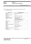
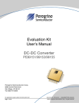
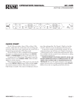
YTA Series
Temperature Transmitter
Fieldbus Communication
User’s
Manual
Manual Change No. 12-006
Please use the attached sheets for the pages listed below in the following manuals.
IM 01C50T02-01E (7th)
Contents of Correction
Page and Item
Page 8-2, 8-5
ATEX Documentation
Page 8-6
Change the applicable standards.
Change Marking Code for ATEX Type of Protection “n”.
Change the applicable standards.
8.1.3 FM Certification
Page 8-9
Deleted.
SAA Flameproof Type
Page 9-2
Change the notation of the table.
9.2 Optional Specifications
May 1, 2012
Yokogawa Electric Corporation
8. HANDLING CAUTION
Note 2. Wiring
* All wiring shall comply with Canadian
Electrical Code Part I and Local Electrical
Codes.
* In hazardous location, wiring shall be in
conduit as shown in the figure.
* WARNING: A SEAL SHALL BE INSTALLED WITHIN 50 cm OF THE
ENCLOSURE.
UN SCELLEMENT DOIT ÊTRE
INSTALLÉ À MOINS DE 50 cm DU
BOÎTIER.
* When installed in Division 2, “FACTORY
SEALED, CONDUIT SEAL NOT
REQUIRED”.
Note 3. Operation
* Keep strictly the “WARNING” on the label
attached on the transmitter.
WARNING: OPEN CIRCUIT BEFORE
REMOVING COVER.
OUVRIR LE CIRCUIT AVANT
D´ENLEVER LE COUVERCLE.
* Take care not to generate mechanical spark
when access to the instrument and peripheral
devices in hazardous location.
Note 4. Maintenance and Repair
* The instrument modification or parts
replacement by other than authorized
representative of Yokogawa Electric Corporation is prohibited and will void Canadian
Standards Explosionproof Certification.
8.1.2
Note 2. Electrical Data
* Supply voltage: 32 V dc max.
Output signal: 16.6 mA
Note 3. Installation
* All wiring shall comply with local installation requirement.
* The cable entry devices shall be of a
certified flameproof type, suitable for the
conditions of use.
Note 4. Operation
* Keep strictly the “WARNING” on the label
on the transmitter.
WARNING: AFTER DE-ENERGIZING,
DELAY 5 MINUTES BEFORE OPENING.
WHEN THE AMBIENT TEMP. 70°C,
USE THE HEATRESISTING CABLES OF
HIGHER THAN 90°C]
* Take care not to generate mechanical spark
when access to the instrument and peripheral
devices in hazardous location.
Note 5. Maintenance and Repair
* The instrument modification or parts
replacement by other than authorized
representative of Yokogawa Electric Corporation is prohibited and will void ATEX
Flameproof Certification.
B) ATEX Intrinsically Safe Type
Caution for ATEX Intrinsically safe type.
Note 1. YTA Series temperature transmitters with
optional code /KS25 for potentially explosive
atmospheres:
* No. KEMA 02ATEX1324 X
* Applicable Standard: EN 50014:1997,
EN 50020;2002, EN 50284:19999,
EN 60529:1999
Note 2. Ratings
[Supply circuit]
• EEx ia IIC T4
Type of Protection and Marking Code:
EEx ia IIC T4
Group: II
Category: 1G
Ambient Temperature: –40 to 60°C
Degree of Protection of the Enclosure: IP67
Electrical Data
* When combined with FISCO model IIC
barrier
Ui = 17.5 V, Ii = 360 mA, Pi = 2.52 W,
Ci = 1.5 nF, Li = 8 H
* When combined with barrier
Ui = 24.0 V, Ii = 250 mA, Pi = 1.2 W,
Ci = 1.5 nF, Li = 8 H
ATEX Certification
(1) Technical Data
A) ATEX Flameproof Type and Dust Ignition
Proof Type
Caution for ATEX Flameproof Type and Dust Ignition
Proof Type
Note 1. Model YTA320-F/KF2 temperature transmitters for potentially explosive atmospheres:
* No. KEMA 07ATEX0130
* Applicable Standard: EN 60079-0:2006,
EN 60079-1:2007, EN 61241-0:2006,
EN 61241-1:2004
* Type of Protection and Marking Code: II 2G
Ex d IIC T6/T5, II 2D Ex tD A21 IP67
T70°C, T90°C
* Ambient Temperature for Gas Atmospheres:
–40 to 75°C (T6), –40 to 80°C (T5)
* Ambient Temperature for Dust Atmospheres:
–40 to 65°C (T70°C), –40 to 80°C (T90°C)
* Enclosure: IP67
8-2
IM 01C50T02-01E
8. HANDLING CAUTION
(1) FISCO Model
• EEx ia IIB T4
Type of Protection and Marking Code:
EEx ia IIB T4
Group: II
Category: 1G
Ambient Temperature: –40 to 60°C
Degree of Protection of the Enclosure: IP67
Electrical Data
* When combined with FISCO model IIB
barrier
Ui = 17.5 V, Ii = 380 mA, Pi = 5.32 W,
Ci = 1.5 nF, Li = 8 H
Non-Hazardous
Locations
Hazardous Locations
Terminator
(FISCO Model)
Supply Unit
(FISCO Model)
Ex i
U
U
I
Terminator
Data
HandheldTerminal
1 23 4 5
Supply
Sensor
YTA
[Sensor circuit]
Uo = 7.7 V, Io = 70 mA, Po = 140 mW,
Co = 1.6 F, Li = 7.2 mH
Note 3. Installation
* All wiring shall comply with local installation requirements. (Refer to the installation
diagram)
Note 4. Maintenance and Repair
* The instrument modification or parts
replacement by other than authorized
representative of Yokogawa Electric Corporation is prohibited and will void KEMA
Intrinsically safe Certification.
Note 5. Special condition for safe use
* Because the enclosure of the Temperature
Transmitter is made of aluminum, if it is
mounted in an area where the use of category 1G apparatus is required, it must be
installed such, that, even in the event of rare
incidents, ignition source due to impact and
friction sparks are excluded.
Note 6. Installation instructions
* From the safety point of view the circuit
shall be considered to be connected to earth.
As this deviates from the FISCO system in
accordance with IEC TS 60079-27 care has
to be taken that the (local) installation
requirements are taken into account as well.
Field Instruments
(Passive)
F0802.EPS
I.S. fieldbus system complying with FISCO
The criterion for such interconnection is that the
voltage (Ui), the current (Ii) and the power (Pi), which
intrinsically safe apparatus can receive, must be equal
or greater than the voltage (Uo), the current (Io) and the
power (Po) which can be provided by the associated
apparatus (supply unit). In addition, the maximum
unprotected residual capacitance (Ci) and inductance
(Li) of each apparatus (other than the terminators)
connected to the fieldbus line must be equal or less
than 5 nF and 10 H respectively.
Supply unit
The supply unit must be certified by a notify body as
FISCO model and following trapezoidal or rectangular
output characteristic is used.
Uo = 14 . . . 24 V (I.S. maximum value)
Io based on spark test result or other assessment,
ex. 133 mA for Uo = 15 V (Group IIC, rectangular
characteristic)
No specification of Lo and Co in the certificate and on
the label.
Cable
The cable used to interconnect the devices needs to
comply with the following parameters:
loop resistance R': 15 . . . 150 Ω/km
inductance per unit length L': 0.4 . . . 1 mH/km
capacitance per unit length C': 80 . . . 200 nF/km
C' = C' line/line + 0.5 C' line/screen, if both lines
are floating
or
C' = C' line/line + C' line/screen, if the screen is
connected to one line
length of spur cable: max. 30 m (EEx ia IIC T4) or
120 m (EEx ia IIB T4)
length of trunk cable: max. 1 km (EEx ia IIC T4)
or 1.9 km (EEx ia IIB T4)
8-3
IM 01C50T02-01E
8. HANDLING CAUTION
Terminators
The terminator must be certified by a notify body as
FISCO model and at each end of the trunk cable an
approved line terminator with the following parameters
is suitable:
(2) Entity Model
Non-Hazardous
Locations
Hazardous Locations
Terminator
Supply Unit
R = 90 . . . 100 Ω
C = 0 . . . 2.2 F.
The resistor must be infallible according to IEC 6007911. One of the two allowed terminators might already
be integrated in the associated apparatus (bus supply
unit).
Ex i
U
U
I
Terminator
Data
HandheldTerminal
1 23 4 5
Supply
Sensor
YTA
Field Instruments
(Passive)
FIELD INSTRUMENTS
Intrinsically safe ratings of the transmitter (FIELD
INSTRUMENTS) are as follows:
F0803.EPS
I.S. fieldbus system complying with Entity model
Supply/output circuit
I.S. values Power supply-field device:
Po Pi, Uo Ui, Io Ii
Calculation of max. allowed cable length:
Ccable Co - ∑ci - ∑ci (Terminator)
Lcable Lo - ∑Li
EEx ia IIC T4
Maximum Voltage (Ui) = 17.5 V
Maximum Current (Ii) = 360 mA
Maximum Power (Pi) = 2.52 W
Internal Capacitance (Ci) = 1.5 nF
Internal Inductance (Li) = 8 H
FIELD INSTRUMENTS
Intrinsically safe ratings of the transmitter (FIELD
INSTRUMENTS) are as follows:
EEx ia IIB T4
Maximum Voltage (Ui) = 17.5 V
Maximum Current (Ii) = 380 mA
Maximum Power (Pi) = 5.32 W
Internal Capacitance (Ci) = 1.5 nF
Internal Inductance (Li) = 8 H
Supply/output circuit
EEx ia IIC T4
Maximum Voltage (Ui) = 24.0 V
Maximum Current (Ii) = 250 mA
Maximum Power (Pi) = 1.2 W
Internal Capacitance (Ci) = 1.5 nF
Internal Inductance (Li) = 8 H
Sensor circuit
EEx ia IIC T4
Maximum Voltage (Uo) = 7.7 V
Maximum Current (Io) = 70 mA
Maximum Power (Po) = 140 mW
External Capacitance (Co) = 1.6 F
External Inductance (Lo) = 7.2 mH
Sensor circuit
EEx ia IIC T4
Maximum Voltage (Uo) = 7.7 V
Maximum Current (Io) = 70 mA
Maximum Power (Po) = 140 mW
External Capacitance (Co) = 1.6 F
External Inductance (Lo) = 7.2 mH
Number of Devices
The number of devices (max. 32) possible on a
fieldbus link depends on factors such as the power
consumption of each device, the type of cable used,
use of repeaters, etc.
Number of Devices
The number of devices (max. 32) possible on a
fieldbus link depends on factors such as the power
consumption of each device, the type of cable used,
use of repeaters, etc.
8-4
IM 01C50T02-01E
8. HANDLING CAUTION
C) ATEX Type of Protection “n”
Caution for ATEX Type of Protection “n”
Note 1. Model YTA320-F/KN25 temperature transmitters for potentially explosive atmospheres:
*Applicable Standard: EN 60079-15: 2005,
EN 60079-0: 2009
* Type of Protection and Marking Code: II 3G
Ex nL IIC T4 Gc
* Temperature Class: T4
* Ambient Temperature: –30 to 70°C
* Enclosure: IP67
Note 2. Electrical Data
[Supply Input]
Maximum input voltage, Ui = 32Vdc
Effective internal capacitance, Ci = 1.5 nF
Effective internal inductance, Li = 8 H
[Sensor Output]
Maximum output voltage, Uo = 7.7 V
Maximum output current, Io = 70 mA
Maximum output power, Po = 140 mW
Maximum allowed external capacitance, Co
= 1.6 F
Maximum allowed external inductance, Lo
= 7.2 mH
Note 3. Operation
• Keep strictly the “WARNING” on the label
on the transmitter.
WARNING: POTENTIAL ELECTROSTATIC CHARGING HAZARD.
SEE USER’S MANUAL BEFORE
USE.
Note 4. Special condition for safe use
• Avoid any actions that cause the generation
of electrostatic charge on the non-metallic
parts, such as rubbing with a dry cloth on
coating face of product.
Note 5. Installation Diagram
(2) Electrical Connection
The type of electrical connection is stamped near
the electrical connection port according to the
following marking.
T0801.EPS
Location of the marking
F0804.EPS
(3) Installation
WARNING
All wiring shall comply with local installation
requirement and local electrical code.
(4) Operation
WARNING
• OPEN CIRCUIT BEFORE REMOVING
COVER. INSTALL IN ACCORDANCE WITH
THIS USER’S MANUAL
• Take care not to generate mechanical sparking
when access to the instrument and peripheral
devices in hazardous locations.
(5) Maintenance and Repair
WARNING
The instrument modification or parts replacement
by other than authorized Representative of
Yokogawa Electric Corporation is prohibited and
will void the certification.
Terminator
Temperature
Transmitter
Field Instruments
Field Instruments
Hazardous Area
Safe Area
[nL] apparatus
F0807.EPS
8-5
IM 01C50T02-01E
8. HANDLING CAUTION
(6) Name Plate
* Dust-ignitionproof for Class II/III, Division
1, Groups E, F and G.
* Enclosure rating: NEMA 4X.
* Temperature Class: T6
* Ambient Temperature: –40 to 60°C
* Supply Voltage: 32 V dc max.
Note 2. Wiring
* All wiring shall comply with National
Electrical Code ANSI/NEPA70 and Local
Electrical Codes.
* “FACTORY SEALED, CONDUIT SEAL
NOT REQUIRED”.
Note 3. Operation
* Keep strictly the “WARNING” on the
nameplate attached on the transmitter.
WARNING: OPEN CIRCUIT BEFORE
REMOVING COVER.
“FACTORY SEALED, CONDUIT SEAL
NOT REQUIRED”.
INSTALL IN ACCORDANCE WITH THE
INSTRUCTION MANUAL IM 1C50B1.
* Take care not to generate mechanical spark
when access to the instrument and peripheral
devices in hazardous location.
Note 4. Maintenance and Repair
* The instrument modification or parts
replacement by other than authorized
representative of Yokogawa Electric Corporation is prohibited and will void Factory
Mutual Explosionproof Approval.
Name plate for intrinsically safe type
TEMPERATURE
TRANSMITTER
0344
II 1G
No.
YTA
EEx ia IIC T4
AMB.TEMP.-40 to 60°C
ENCLOSURE: IP67
SUPPLY INPUT
Ui=24V,li=250mA
Pi=1.2W
Ci=1.5nF,Li=8µH
SENSOR OUTPUT
Uo=7.7V,lo=70mA
Po=140mW
Co=1.6µF,Lo7.2=mH
Entity : 9 to 24V DC
FISCO : 9 to 17.5V DC
TOKYO 180-8750 JAPAN
EEx ia IIC T4
AMB.TEMP.-40 to 60°C
ENCLOSURE: IP67
SUPPLY INPUT
Ui=17.5V,li=360mA
Pi=2.52W
Ci=1.5nF,Li=8µH
SENSOR OUTPUT
Uo=7.7V,lo=70mA
Po=140mW
Co=1.6µF,Lo7.2=mH
EEx ia IIB T4
AMB.TEMP.-40 to 60°C
ENCLOSURE: IP67
SUPPLY INPUT
Ui=17.5V,li=380mA
Pi=5.32W
Ci=1.5nF,Li=8µH
SENSOR OUTPUT
Uo=7.7V,lo=70mA
Po=140mW
Co=1.6µF,Lo7.2=mH
Name plate for flameproof type
0344
TEMPERATURE
TRANSMITTER
II 2G
No. KEMA 02ATEX2155
EEx d IIC T6
Tamb -40 TO 75°C
EEx D IIC T5
Tamb -40 TO 80°C
ENCLOSRE: IP67
SUPPLY 32 V dc MAX
OUTPUT 17.5 mA MAX
YTA
9 32 V DC
WARNING
AFTER DE-ENERGIZING, DELAY 5 MINUTES BEFORE OPENING.
WHEN THE AMBIENT TEMP. ≥ 70°C, USE THE HEAT-RESISTING CABLES ≥ 90°C.
TOKYO 180-8750 JAPAN
F0805.EPS
MODEL: Specified model code.
SUFFIX: Specified suffix code.
STYLE: Style code.
SUPPLY: Supply voltage.
NO.: Serial number and year of production*1.
OUTPUT: Output signal.
FACTORY CAL: Specified calibration range.
TOKYO 180-8750 JAPAN:
The manufacturer name and the address*2.
*1: The production year
The third figure from the left of the serial number
shows the year of production. The relation between
the third figure and the production year is shown
below.
Third figure
D
E
F
G
H
J
K
Production year 2004 2005 2006 2007 2008 2009 2010
For example, the production year of the product
engraved in “NO.” column on the name plate as
follows is 2007.
B) FM Intrinsically Safe Type
Model YTA Series temperature transmitters with
optional code /FS15.
* Applicable Standard: FM 3600, FM 3610,
FM 3611, FM 3810, NEMA250,
ANSI/ISA-60079-0, ANSI/ISA-60079-11
• FM Intrinsically Safe Approval
[Entity Model]
Class I, II & III, Division 1, Groups A, B, C, D, E,
F & G, Temperature Class T4 Ta=60°C, Type 4X
and Class I, Zone 0, AEx ia IIC, Temperature Class
T4 Ta=60°C, Type 4X
[FISCO Model]
Class I, II & III, Division 1, Groups A, B, C, D, E,
F & G, Temperature Class T4 Ta=60°C, Type 4X
and Class I, Zone 0, AEx ia IIC, Temperature Class
T4 Ta=60°C, Type 4X
• Nonincendive Approval
Class I, Division 2, Groups A, B, C & D and Class
I, Zone 2, Group IIC
Class II, Division 2, groups F & G,
Temperature Class: T4
Enclosure: NEMA 4X
C2G218541
2007
*2: “180-8750” is a zip code which represents the
following address.
2-9-32 Nakacho, Musashino-shi, Tokyo Japan
8.1.3 FM Certification
A) FM Explosionproof Type
Caution for FM Explosionproof type
Note 1. Model YTA320-F /FF1 temperature transmitters are applicable for use in hazardous
locations:
* Applicable Standard: FM 3600, FM 3615,
FM 3810, NEMA250
* Explosionproof for Class I, Division 1,
Groups A, B, C, and D.
8-6
IM 01C50T02-01E
8. HANDLING CAUTION
• Electrical Connection: 1/2 NPT female
• Caution for FM Intrinsically safe type. (Following
contents refer to “DOC. No. IFM018-A12 p.1, p.2,
p.3, and p.3-1.”)
*7: No revision to drawing without prior Factory
Mutual Research Approval.
*8: Terminator must be FM Approved.
Electrical Data:
• Rating 1 (Entity and nonincendive)
For Groups A, B, C, D, E, F, and G or Group IIC
Maximum Input Voltage Vmax: 24 V
Maximum Input Current Imax: 250 mA
Maximum Input Power Pi: 1.2 W
Maximum Internal Capacitance Ci: 1.5 nF
Maximum Internal Inductance Li: 8 H
or
• Rating 2 (FISCO)
For Groups A, B, C, D, E, F, and G or Group IIC
Maximum Input Voltage Vmax: 17.5 V
Maximum Input Current Imax: 360 mA
Maximum Input Power Pi: 2.52 W
Maximum Internal Capacitance Ci: 1.5 nF
Maximum Internal Inductance Li: 8 H
or
• Rating 3 (FISCO)
For Groups C, D, E, F, and G or Group IIB
Maximum Input Voltage Vmax: 17.5 V
Maximum Input Current Imax: 380 mA
Maximum Input Power Pi: 5.32 W
Maximum Internal Capacitance Ci: 1.5 nF
Maximum Internal Inductance Li: 8 H
and
• Rating 4 (Sensor circuit)
Maximum Output Voltage Uo: 6.7 V
Maximum Output Current Io: 60 mA
Maximum Output Power Po: 100 mW
Maximum External Capacitance Co: 10 F
Maximum External Inductance Lo: 10 H
IFM018-A12
Installation Diagram
(Intrinsically safe, Division 1 Installation)
Terminator
Temperature 1
Transmitter 2
3
SUPPLY
SENSOR 4
5
Transmitter
Transmitter
Hazardous Location
Non Hazardous Location
Terminator
Safety Barrier
F0809.EPS
*1: Dust-tight conduit seal must be used when installed
in Class II and Class III environments.
*2: Control equipment connected to the Associated
Apparatus must not use or generate more than 250
Vrms or Vdc.
*3: Installation should be in accordance with ANSI/
ISA RP12/6 “Installation of Intrinsically Safe
Systems for Hazardous (Classified) Locations” and
the National Electrical Code (ANSI/NFPA 70)
Sections 504 and 505.
*4: The configuration of Associated Apparatus must be
Factory Mutual Research Approved under FISCO
Concept.
*5: Associated Apparatus manufacturer’s installation
drawing must be followed when installing this
equipment.
*6: The YTA Series are approved for Class I, Zone 0,
applications. If connecting AEx (ib) associated
Apparatus or AEx ib I.S. Apparatus to the Zone 2,
and is not suitable for Class I, Zone 0 or Class I,
Division 1, Hazardous (Classified) Locations.
Note: In the rating 1, the output current of the barrier must be
limited by a resistor “Ra” such that Io=Uo/Ra. In the rating
2 or 3, the output characteristics of the barrier must be the
type of trapezoid which are certified as the FISCO model
(See “FISCO Rules”). The safety barrier may include a
terminator. More than one field instruments may be
connected to the power supply line.
FISCO Rules
The FISCO Concept allows the interconnection of
intrinsincally safe apparatus to associated apparatus not
specifically examined in such combination. The
criterion for such interconnection is that the voltage
(Ui), the current (Ii) and the power (Pi) which intrinsically safe apparatus can receive and remain intrinsically safe, considering faults, must be equal or greater
than the voltage (Uo, Voc, Vt), the current (Io) and the
power (Po) which can be provided by the associated
apparatus (supply unit). In addition, the maximum
unprotected residual capacitance (Ci) and inductance
8-7
IM 01C50T02-01E
8. HANDLING CAUTION
System evaluations
The number of passive device like transmitters,
actuators, hand held terminals connected to a single
bus segment is not limited due to I.S. reasons.
Furthermore, if the above rules are respected, the
inductance and capacitance of the cable need not to be
considered and will not impair the intrinsic safety of
the installation.
(Li) of each apparatus (other than the terminators)
connected to the fieldbus must be less than or equal to
5 nF and 10 H respectively.
In each I.S. fieldbus segment only one active source,
normally the associated apparatus, is allowed to
provide the necessary power for the fieldbus system.
The allowed voltage Uo of the associated apparatus
used to supply the bus is limited to the range of 14 V
dc to 24 V dc. All other equipment connected to the
bus cable has to be passive, meaning that the apparatus
is not allowed to provide energy to the system, except
to a leakage current of 50 A for each connected
device.
HAZARDOUS AREA
SAFE AREA
Supply Unit
(FISCO Model)
Terminator
(FISCO Model)
Ex i
U
Supply unit
Trapezoidal or rectangular output characteristic only
U
I
Uo = 14...24 V (I.S. maximum value)
HandheldTerminal
Io according to spark test result or other assessment, e.g. 133 mA for Uo = 15 V (Group IIC,
rectangular characteristic) No specification of Lo
and Co in the certificate and on the label.
Terminator
Data
Field Instruments
(Passive)
F0808.EPS
I.S. fieldbus system complying with FISCO model
Cable
The cable used to interconnect the devices needs to
comply with the following parameters:
Installation Diagram
(Nonincendive, Division 2 Installation)
loop resistance R’: 15...150 Ω/km
inductance per unit length L’: 0.4...1 mH/km
capacitance per unit length C’: 80...200 nF/km
C’=C’line/line0.5 C’line/screen, if both lines are
floating
Terminator
Temperature 1
Transmitter 2
3
SUPPLY
SENSOR 4
5
or
C’=C’line/lineC’line/screen, if the screen is
connected to one line
length of spur cable: max. 30 m (Group IIC) or 120
m (Group IIB)
length of trunk cable: max. 1 km (Group IIC) or 1.9
km (Group IIB)
Transmitter
Transmitter
Terminators
At each end of the trunk cable an approved line
terminator with the following parameters is suitable:
Hazardous Location
Non Hazardous Location
R = 90...100 Ω
C = 0...2.2 F
The resistor must be infallible according to IEC 6007911. One of the two allowed terminators might already
be intergrated in the associated apparatus (bus supply
unit)
Terminator
(Nonincendive)
Power Supply
FM Approved Associated
Nonincendive Field Wiring Apparatus
Vt or Voc
It or Isc
Ca
La
F0810.EPS
8-8
IM 01C50T02-01E
8. HANDLING CAUTION
8.1.4 IECEx Certification
*1: Dust-tight conduit seal must be used when installed
in Class II and Class III environments.
*2: Installation should be in accordance with and the
National Electrical Code® (ANSI/NFPA 70)
Sections 504 and 505.
*3: The configuration of Associated Nonincendive
Field Wiring Apparatus must be FM Approved.
*4: Associated Nonincendive Field Wiring Apparatus
manufacturer’s installation drawing must be
followed when installing this equipment.
*5: No revision to drawing without prior FM Approvals.
*6: Terminator and supply unit must be FM Approved.
*7: If use ordinary wirings, the general purpose
equipment must have nonincendive field wiring
terminal approved by FM Approvals.
*8: The nonincendive field wiring circuit concept
allows interconection of nonincendive field wiring
apparatus with associated nonincendive field wiring
apparatus, using any of the wiring methods permitted for unclassified locations.
*9: Installation requirements;
Vmax Voc or Vt
Imax = see note 10
Ca Ci + Ccable
La Li + Lcable
*10: For this current controlled circuit, the parameter
(Imax) is not required and need not be aligned with
parameter (Isc or It) of the barrier or associated
nonincendive field wiring apparatus.
A) IECEx Flameproof Type and Dust Ignition
Proof Type
Caution for IECEx flameproof type and Dust Ignition
Proof Type
Note 1. Model YTA320/SF2 temperature transmitters
are applicable for use in hazardous locations:
* No. IECEx KEM 07.0044
* Applicable Standard: IEC 60079-0:2004,
IEC 60079-1:2007-4, IEC 61241-0:2004,
IEC 61241-1:2004
* Type of Protection and Marking Code:
Ex d IIC T6/T5, Ex tD A21 IP67 T70°C,
T90°C
* Ambient Temperature for Gas Atmospheres:
–40 to 75°C (T6), –40 to 80°C (T5)
* Ambient Temperature for Dust Atmospheres:
–40 to 65°C (T70°C), –40 to 80°C (T90°C)
* Enclosure: IP67
Note 2. Electrical Data
* Supply voltage: 42 V dc max.
* Output signal: 4 to 20 mA
Note 3. Installation
* All wiring shall comply with local installation requirement.
Electrical Data:
• Supply Input (+ and –)
Maximum Input Voltage Vmax: 32 V
Maximum Internal Capacitance Ci: 1.5 nF
Maximum Internal Inductance Li: 8 H
• Sensor Output (1 to 5)
Maximum Output Voltage Voc: 6.7 V
Maximum External Capacitance Co: 1.6 F
Maximum External Inductance Lo: 7.2 mH
8-9
IM 01C50T02-01E
9. GENERAL SPECIFICATIONS
9.2 Optional Specifications
For items other than those described below, refer to IM 01C50B01-01E.
Item
ATEX
Description
ATEX Flameproof and Dust Ignition Proof Approval
Electrical Connection: 1/2 NPT female and M20 female
Code
KF2
ATEX Intrinsically Safe Approval
Electrical Connection: 1/2 NPT female and M20 female
KS25
ATEX Type n Approval
Electrical Connection: 1/2 NPT female and M20 female
KN25
FM Explosionproof Approval
Electrical Connection: 1/2 NPT female
FF1
FM Intrinsically Safe Approval
Electrical Connection: 1/2 NPT female
FS15
Canadian Standards
Association (CSA)
CSA Explosionproof Approval
Electrical Connection: 1/2 NPT female
CF1
IECEx
IECEx Flameproof and Dust ignition proof Approval
Electrical Connection: 1/2 NPT female and M20 female
SF2
Factory Mutual (FM)
IECEx Intrinsically safe and type n
Electrical Connection: 1/2 NPT female or M20 female
PID function
PID control function (one block)
SS25
LC1
PID control function (2 blocks)
LC2
T0901E.EPS
9-2
IM 01C50T02-01E