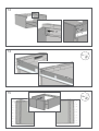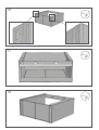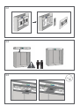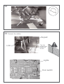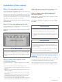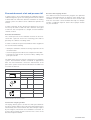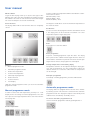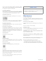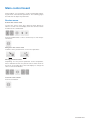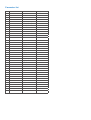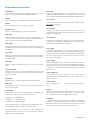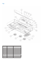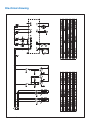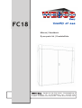
1
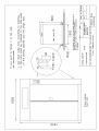
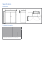
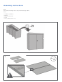
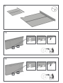
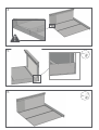
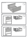
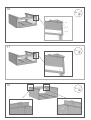
Manual / Handbuch
Spare parts list / Ersatzteilliste
Equipment Imp.-Exp. GmbH • Zitterpappelweg 9
D - 22391 Hamburg • Tel.: + 49 40 60009468-0 • Fax: + 49 40 536 75 01
E - M a i l : i n f o @ w e s c o - n a v y. c o m • w w w . w e s c o - n a v y. c o m
•
Safety regulations
Throughout this manual you will find text warnings in text boxes: “WARNING” and “CAUTION”. In these boxes you’ll find the
safety measurements you’ll have to take; end user, service staff
or installation staff.
CAUTION
Indicates hazardous situation that, if not avoided, could cause
minor personal injury or property damage.
WARNING
To minimize the risk of fire, electrical shock, personal injuries
or death when the cabinet is in use the following precautions
must be followed:
1.
Read the instruction before using the drying cabinet.
2.
Follow the instructions in step 4 for proper grounding.
3.
Never dry textiles that have been washed, dipped or exposed to fire dangerous substances or fluids.
4.
Never add fire dangerous or explosives substances to the
cabinet.
5.
The cabinet is not a toy. Look after children who are around
the cabinet.
6.
Never connect the cabinet with an extension cable.
7.
Only use the cabinet for what it is designed for: drying
clothes.
8.
Always turn off the main switch before performing any service on the cabinet. Only authorized service technicians
should perform service.
9.
Always follow the installation manual. The electrical connections must be installed by authorized personnel.
WARNING
Indicates hazardous situation that, if not avoided, could cause
severe personal injury.
You will also find precautions marked: IMPORTANT and NOTE.
These are followed by information of what should be considered.
IMPORTANT: to inform the reader of special steps that must
be taken in order to prevent injuries on the cabinet.
NOTE: to inform what is important to know, but it cannot
cause personal injuries or injury on the cabinet.
10. Keep after the cabinet. If it is exposed to violence there is a
risk that certain security functions will stop working. Please
contact your nearest service partner if you are unsure of
the cabinet’s status.
11. If the electrical cable is damaged, it must immediately be
changed by a person with electrical authorization.
12. The doors shall always be shut when the cabinet is in use.
Do not try to manipulate the lock of the doors. It can lead
to personal injuries. If the cabinet does not stop when the
doors are opened during the drying phase, call for service.
The cabinet shall not be used if the drying program is active when the doors are open!
13. Look after the area around the evacuating pipe so it is
clean from dust and dirt.
14. To get the best drying result, follow the garments washing
and drying advice.
15. Never use the cabinet if any panel is broken or removed.
16. Never use the cabinet if any parts are broken or if the inside
is broken.
17. Never try to manipulate or connect past any safety functions.
18. If the cabinet is not assembled after the manufacturer’s
instructions, there is a risk that the cabinet can cause personal injuries or injuries on property.
©PODAB 2009
Specification
Dimensions
1800
800
Technical information
Loading capacity, number of suits
6
Evacuated air, max, m³/h
600
Heating effect, kW
12,0
Total effect, kW
12,45
Membrane
Cotton wool
Drying capacity, g/min *
55
45
Drying time, min *
175
65
Energy consumption, kWh/kg
0,98
0,34
Part No
131027
*Drying of 20 kg fire suits (dry weight) washed and high-spinned to 5o %
residual moisture for membrane suits and 15 % for cotton wool suits.
68
R7
790
1955
250
200
900
Assembly instructions
Tools
You need the following tools to easily install the drying cabinet,
FC 18:
s¬ Cordless screwdriver
s¬ Wrench
s¬ Hex key 3 and 5 mm
s¬ Level
s¬ Torx screwdriver bit no. 25
1
4x
©PODAB 2009
2
6x
3a
3b
4
5
5x
6
4x
©PODAB 2009
7(repeat 4-6)
9x
8
6x
9
1x
10
6x
11
1x
12
2x
©PODAB 2009
13
14
2x
15
26x
16
2x
17
6x
18
4x
©PODAB 2009
19
2x
20
21
22
23
24
2x
©PODAB 2009
25
8x
26
8x
27
28
4x
29 Connect the cables
Keypad
LCD
The side
without hole
pattern to
the left.
Lights
Door switch
©PODAB 2009
30
4x
31
Installation of the cabinet
Step 1: Put the cabinet in place
Place the cabinet with enough space in front of the cabinet and
on the sides to be able to open the doors.
The feet of the cabinet can be adjusted from the inside with
the help of a Hex key. The feet must stand free on the floor and
have an even weight distribution. Use a leveler and control that
the cabinet is leveled; horizontally and vertically.
NOTE: We recommend that the cabinet is installed on a firm
and leveled floor.
NOTE: If the cabinet is not connected according to these
recommendations, the warranty is no longer valid.
Step 4: Connect the drying cabinet to
the main switch
NOTE: Only an authorized electrician is allowed to install
the electrical connection.
The cabinet is prepared for electrical connections: 400 V,
3-N, 50 Hz.
Step 2: Fasten the cabinet to the wall
Use the stoppers, screws and washers to secure the cabinet
through the back plates. (See picture.)
WARNING
NOTE: Please control that the cabinet is leveled and cannot
be tilted.
To prevent that fire and electric shock appear, the cabinet MUST
be connected according to the color codes on the cables.
It is always the buyer that has the responsibility to check that
an authorized electrician makes the electrical connections of
the cabinet.
Fastening points
WARNING
To prevent personal injuries, the cabinet shall always be connected permanently through an all pole main switch. Always
ground the cabinet!
ATTENTION
Never place the cabinet in direct contact with wooden material. Always use the stoppers to prevent the cabinet from direct
contact to a wooden wall. Leave a security distance of at least
30 mm.
Step 3: Connect the cabinet to the
ventilation channel
For further instructions, se page 20: Requirements for ventilation.
Also check that the connecting cable has a strain relief bushing.
If not, there is a risk that the cabinet will be live.
Step 5: Control that the heating relay is
working
Shut the doors and start the cabinet, after about 3 seconds you
can hear when the heat relays hit. Wait a couple of minutes and
control that the outgoing air channel becomes warm.
If the outgoing air channel does not get warm, go back to step 4
and control that the electrical connection is installed correctly.
s¬ Do not use ventilation channels made of plastic or foil.
s¬ Place the cabinet so that the ventilation channel is as short as
possible.
s¬ Make sure that the ventilation channel is cleaned when a new
cabinet is installed.
s¬ Use a 160 mm rigid or flexible metal duct to the evacuation
connection.
s¬ If you use rigid ducts, it is important that the male connector of
the ventilation tube on each section follows the air direction.
s¬ The construction shall be as straight as possible.
s¬ Always isolate ducts that go through non-isolated areas. The
condensation makes dust and dirt get stuck in the channel.
©PODAB 2009
Requirements for ventilation
WARNING
A drying cabinet produces inflammable dust. To minimize the
risk for fire, the evacuation of the cabinet must be connected
to a ventilation channel that evacuates the air.
Requirements for incoming air
In order to make the cabinet work properly, it is very important
that there is enough incoming air in the room. The incoming air
must be at least 4 00 m³/hour.
Never let the evacuated air into a room or a surrounding where
there is a risk for ignition.
If the cabinet is placed in a room where the incoming air is not
enough, we recommend that you install an air exchanger. Contact PODAB ffor more information.
Do not use ventilation channels in plastic or fire dangerous
material.
Ventilation channel – design
IMPORTANT: Always make the channels as short as possible.
Ventilation channel – choice of material
Ventilation channel, ducts, connections etc are not included.
The ventilation channels shall be at least 160 mm in diameter
and should not have channels or similar on the inside.
We recommend that the ventilation system is built with rigid
metal ducts for best result. Flexible evacuating ducts for drying
cabinets can also be used.
NOTE: Never use flexible ducts through walls or other covered areas.
NOTE: Do not screw or nit the ventilation channel, so that
the screws will come through the inside of the pipe. This
construction will gather dust and impaire the cabinet’s performance.
The channel shall always be separated from the other ventilation in the house.
NOTE: If a drying cabinet is installed in an old ventilation
channel, please clean the channel properly.
In order to make the cabinet work properly, the incoming airflow must be enough. The amount of evacuated air per hour
is depending on how high the pressure fall in the ventilation
channel is.
Material, the design and the length of the channel have a large
impact on the air flow. In order to get the best possible performance, the pressure fall shall be as low as possible.
When the air is transported through the channel, it is exposed
to different kind of resistance. Factors that give a low pressure
fall:
s¬ Smooth inner walls on the pipe
s¬ Large diameter on the pipe
s¬ Short length on the pipe
s¬ Few curves
s¬ Few angels (90 degrees)
Evacuated amount of air and pressure fall
Decrease the outgoing air flow
In order to get FC 18 to work properly, the ventilation channel
shall be designed to get an out coming air flow from the cabinet
of about 300 m³/h. When the cabinet is installed to an existing
channel system, the cabinet can be calibrated to optimize the
air flow.
The cabinets function and automatic programs are optimized
for the recommended air flow of 300 m3/h. If the design of the
ventilation is made so that evacuated air flow exceeds 300
m3/h, the evacuation can be throttled with help of a damper.
Contact a ventilation expert in order to find a proper solution
for your ventilation.
In order to gain this air flow, the pressure fall must not exceed
210 Pa. By an airflow of 300 m³/h and a diameter of the pipe
of 160 mm, this corresponds to a straight, smooth ventilation
channel of 140 m.
Pressure fall estimation
The counter pressure in the ventilation channel can be measured with a pressure meter. The measuring point shall be
placed by the cabinets evacuating outlet.
In order to estimate the pressure fall without meter equipment
we recommend the following:
s¬ Identify the ventilation channel’s incoming components in the
air flow direction.
s¬ Check the part pressure fall for each component in the table.
s¬ Calculate the total amount of pressure fall by adding each
parts pressure fall.
The table shows the most common components in a ventilation
system. The information shall be considered as approximate
data. For more information, contact the manufacturer of the
parts of the system. Please note that the data in the table is for
an air flow of 300 m³/h.
Component
Pressure fall
Circular channel
Ø
Pipe bends 90º
ø, mm
Pa/m
125
4,5
160
1,5
ø, mm
r, mm
Pa/bend
125
125
10
160
160
4
Ø
r
Reduction
Transition, mm
Pa/reduction
125 to 160
4
160 to 125
17
Example: 10 m long 160 mm channel with 3 pipe curves which gives an estimated
pressure fall of (6 x 1,5) + (3 x 4) = 21 Pa.
Increase the outgoing air flow
The drying cabinet gets its air from the small space between
the doors and the cabinet. An increased incoming air flow gives
automatically an increased outflow. The doors are kept in place
by two magnets, which both are assembled to a bracket. To
increase the incoming air flow, loosen the two screws on the
bracket and push it forward.
©PODAB 2009
User manual
Fill the cabinet
To get the best drying result: try to dry the same type of firefighting suits at the same time. Distribute the clothing evenly in
the cabinet. If less than six suits are dried, remove the hangers
not used. The dampers are closed automatically.
Close the doors
The drying cabinet will not start until the doors are completely
closed.
1
Increase or reduce the temperature with the arrow buttons 3 and 4.
There are three levels:
Minimum (MIN) = 40ºC
Medium (MED) = 60ºC
Maximum (MAX) = 80ºC
The degrees stated above, show the maximum temperature of
the warm air stream.
Set the time
Increase or reduce the drying time with the arrow buttons 6 and
7. The drying time can be increased to maximum 4 h. Lower
temperature requires longer drying time.
2
Start
Push button 5 to start the cabinet.
8
Pause programme
To pause a working programme, open the doors. The drying
time is paused. The cabinet will start again when the doors are
closed and the start button is pushed. If the doors are left open
longer than 10 minutes, the programme is interrupted.
3
4
5
6
7
Keypad
1. Manual programme mode
Change temperature or time during drying
Temperature and time can be adjusted during the drying process and the programme is in the heating phase. When the
cabinet switches to cool down, neither time nor temperature
can be changed.
2.
Automatic programme mode*
3.
Reduce the temperature
4.
Increase the temperature
5.
Start/stop the programme
Interrupt a programme
6.
Reduce the time
To interrupt a working programme, push the START/STOP.
7.
Increase the time
8.
LCD-display
*Will also change programme when you are in the automatic
programme mode.
Automatic programme mode
Manual programme mode
In order to set the time and temperature, push key no 1. LCDdisplay shows the settings for manual programmes. The cabinet is preset on average temperature 80ºC and 1h and 30 minutes drying time.
The drying cabinet is equipped with the function HTS – Humidity Tracking System. This function is activated in the automatic
programme mode. The drying time adjusts to the laundry in the
cabinet and is controlled by a humidity sensor.
To choose automatic programme mode
Choose automatic programme mode by pushing button 2.
Set the temperature
The FC 18 have three different automatic programmes: Membrane, Cotton wool and Stationwear. For these programmes
the drying time is adjusted automatically.
Programme: Membrane
When automatic mode is activated, the programme Membrane
is set as first choice. Membrane should be used for firefighting
suits with membrane fabric. Drying temperature is 80ºC.
CAUTION
If a program is interrupted before the cool down has finished,
the ceiling of the cabinet could be very hot.
Programme: Cotton wool
To change automatic program, push button no 2 once more.
Maintenance
Installation during winter
The programme Cotton wool should be used for firefighting
suits with cotton wool stuffing. Drying temperature is 80ºC.
Programme: Stationwear
For station and sportswear like T-shirts, sweat-shirts, pants etc.
Drying temperature is 60ºC.
Reactivation of impregnation
The programmes Membrane and Cotton wool have a unique
function. By the end of the drying cycle the cabinets goes into
reactivation mode. During 30 minutes the evacuation of air is
stopped and the temperature is maximized. This hardens the
impregnation of the suits.
If the cabinet is installed a cold winter day (below 0°C) and has
been out in the cold, we recommend that it is kept inside a few
hours before use.
Take good care of the cabinet
Only use a damp cloth with a mild detergent when cleaning the
cabinet.
Never use solvent to clean the display.
Ventilation system
Loosen the ventilation pipe on the cabinet every year and clean
if necessary around the evacuating channel.
IMPORTANT: Always switch off the electricity before starting to work with the cabinet.
Start programme
Push button 5 to start the cabinet.
Pause programme
To pause a working programme, open the doors. The cabinet
will start automatically when the doors are closed, and the start
button is pushed.
Interrupt a programme
Inspect with set intervals the complete ventilation channel;
don’t forget the outer wall. There can easily be leafs and other
rubbish that chokes.
We recommend that you once a year, take down the service
doors and vacuum clean around the fans and elements.
Keep your cabinet efficient and economical
s¬ The ventilation channels shall be as short as possible.
s¬ If possible, dry the same type of textiles at the same time.
s¬ Do not dry with maximum temperature if you do not need to.
To interrupt a working programme, push START/STOP.
Cool down
All programmes, both manual and automatic, have a cool down
phase of 15 minutes. During cool down the textiles are reconditioned and the drying cabinet is cooled down. Time and temperature cannot be changed.
If the doors are opened during the cool down, the fans will continue. This is normal procedure.
©PODAB 2009
Main control board
Drying cabinet, FC 18 Firedryer, can be customized by adjusting the main control board´s parameters. The following pages
describe how to adjust the parameters.
Service menu
Activate the service menu
To enter the service menu; press both left arrow buttons in
about 5 seconds. The LCD-display shows the software version
installed on the control board.
Push the START-button, 5 times continuously, to enter the parameter list.
Navigate in the service menu
To browse in the parameter list, use the two top buttons.
Change parameter values
Depending on if the present parameter shows temperature,
time or ON/OFF-function, the present value is either shown on
the left or on the right side of the LCD-display. To change the
value, use the arrow buttons.
Leave the service menu
Push the start button.
®PODAB 2010
Parameter list
#
Parameter
Alternative
Factory position
1
LANGUAGE
SWE/ENG/FR
ENG
2
MODEL
TS 62, T 196, TS 92, FC 18
FC 18
3
RESET
YES
-
4
DEGREE UNIT
C/F
C
5
MIN TEMP
[-- --], 25 -> [MED-5]
40
6
MED TEMP
[MIN + 5] -> [MAX-5]
60
7
MAX TEMP
[MED + 5]-90
80
8
DEF TEMP
MIN/MED/MAX
MAX
9
SHOW DEGREES
ON/OFF
ON
10
MAX TIME
1:00-09:59
04:00
11
DEF TIME
0:00-[MAX TID]
01:30
12
AUTOPROG
OFF, 1-9
3
13
PR1 TEMP
MIN/MED/MAX
MAX
14
PR1 COEFF A
[0.00] - [1.00]
0,12
15
PR1 COEFF B
[-99]-[+99]
-3
16
PR1 REACTIV
0:00-1:00
00:30
17
PR2 TEMP
MIN/MED/MAX
MAX
18
PR2 COEFF A
[0.00] - [1.00]
0,02
19
PR2 COEFF B
[-99]-[+99]
5
20
PR2 REACTIV
0:00-1:00
00:30
21
PR3 TEMP
MIN/MED/MAX
MED
22
PR3 COEFF A
[0.00] - [1.00]
0,09
23
PR3 COEFF B
[-99]-[+99]
3
24
PR3 REACTIV
0:00-1:00
00:00
25
HYST TEMP
0-20
10
26
COOL DOWN
0:00-0:20
00:15
27
SHOW TEMP+HU
ON/OFF
OFF
28
SHOW LOGO
ON/OFF
ON
29
SOUND
ON/OFF
ON
30
STANDBY
ON/OFF
ON
31
LIGHT TIME
0:00-0:30
00:10
32
PAUSE TIME
0:00-0:30
00:10
33
COIN
ON/OFF
OFF
34
SIGNAL TYPE
PLS/N-0
N-O
35
WORK TIME
-
[000000] h
36
TEST LOOP
ON/OFF
OFF
37
CLEAR E-CODE
YES
-
Explanation of parameters
LANGUAGE
PR# TEMP
FC 18 Firedryer is delivered with English display text as standard. Choose between Swedish, English and French.
Every automatic programme can be adjusted by choosing
temperatures MIN, MED, MAX. The temperature values are the
same as parameters MIN TEMP, MED TEMP and MAX TEMP.
MODEL
Choice of product model. Shall always be in position “FC 18”.
PR# COEFF A
COEFF A affects the automatic drying function. This parameter
RESET
should not be changed.
Resets all parameters to initial factory position.
DEGREE UNIT
Degrees can be displayed in Celsius or Fahrenheit.
MIN TEMP
Setting of minimum temperature level in manual mode. “----“
means that the heating is off. The highest possible degree to be
chosen is affected by parameter MED TEMP.
PR# COEFF B
COEFF B also affects the automatic drying function. Can be
changed if needed. If the value of COEFF B is decreased, the
drying time is prolonged.
PR# REACTIV
This parameter decides the duration of the reactivation phase.
If the time is set to 00:00 the programme hits cool down imme-
MED TEMP
diately after the drying phase is finished.
Setting of medium temperature level in manual mode. Choice
of temperature level is affected by the value of both MIN and
MAX TEMP.
HYST TEMP
MAX TEMP
Setting of maximum temperature level in manual mode. Lowest
temperature level to choose is affected by the value of parameter MED TEMP.
It controls the hysteresis. FC 18 Firedryer is preset to 10ºC.
When the working temperature is attained and the heating elements are turned off, it will be a delay. When the temperature
hits 10ºC, the heating starts again. Shorter hysteresis increase
the energy consumption.
COOL DOWN
DEF TEMP
Sets the default temperature when the user enters manual
mode.
SHOW DEGREES
Manual mode shows the chosen temperature in degrees. This
function can be turned off so that only the symbol on the thermometer is shown.
MAX TIME
After the heating phase, the cabinet has a period of cool down
to recondition the laundry and lower the temperature within the
cabinet. The time is set to 15 minutes. PLEASE NOTE! Without
a sufficient cool down period, the inner plates of the cabinet
will be very hot.
SHOW TEMP+HU
This parameter is for error searching. If set in mode “ON” the
cabinet will show current temperature and air humidity by respective sensors.
Setting of time in manual mode. Maximum 9h 59 minutes.
SHOW LOGO
DEF TIME
This parameter controls the time which is default when the user
enters manual mode.
Turns on and off the PODAB-logo
on the top of the LCD-disPODAB-l
-l
play.
SOUND
AUTOPROG
It is possible to activate up to nine automatic programmes. Default from factory; three pre-programmed choices:
Programme 1 = MEMBRANE
Programme 2 = COTTON WOOL
Programme 3 = STATION WEAR
Each programme has four parameters (see explanation of parameter TEMP, COEFF A, COEFF B and REACTIV).
This parameter controls if the sound shall be on or off. In mode
“ON” you can hear a distinct “beep-noise” every time the buttons are pushed or when a drying period is ended.
STANDBY
In position “ON”, the display background light is automatically
turned off if no button is pushed for two minutes. The display
light is turned on when any button is pushed or if the doors are
opened. In position “OFF” the light is constantly off.
When AUTOPROG is set in mode “OFF” the automatic programmes is inactivated. If the user choose automatic mode, the
display shows “INACTIVATED”.
®PODAB 2010
LIGHT TIME
When the doors open, the light inside the cabinet is turned on.
With the parameter LIGHT TIME you set how long the light will
be on, if the doors are left opened. When the time is up, the
lamp is turned off automatically.
Error codes
LCD
T1
PAUSE TIME
If the doors are opened during drying, the drying programme
is paused. Are the doors left opened for a long time, the programme will stop. The time is adjustable from 0 – 30 minutes.
PLEASE NOTE! If the parameter is set to 0 minutes, the cabinet
will stop the programme as soon as the doors are opened.
The control board’s electronically overheat protection has been activated. The error code is
generated if the temperature rises above 100ºC,
twice within 30 minutes.
Control that the fan motors are working as they
should. Also control the
temperature sensor and
that the cable from the
board is intact.
HU
The control board gets
no signal from the humidity sensor.
Control that the sensor is
connected correctly on
the main control board
and that the cable from
the sensor to the board
is intact.
The cabinet FC 18 Firedryer can be connected to a booking
system. To activate the function, set the parameter in position
“ON”. To start a programme, a connection to the control board’s
COIN-contact is needed.
This parameter is only visible if COIN is activated. COIN is used
when the cabinet is connected to a booking system. Choose
position depending on which type of signal the booking system
is sending. “PLS” stands for pulse and means that the cabinet
is booked per drying period. One pulse gives one drying period.
“N-O” is chosen when the signal is either on or off. The current
programme will always run until finished even if the signal is
broken during the programme.
WORK TIME
The parameter shows the total amount of hours the cabinet
has been on. It is also memorized if the electricity to the control
board is broken.
TEST LOOP
Start the test programme by changing the parameter to “ON”.
The programme can be used to control the components in the
cabinet. Parts are activated as follows: To go to the next step,
press arrow button. The programme goes automatically to the
next level after 30 seconds.
1.
2.
3.
4.
5.
6.
Fans connected to FAN1
Fan connected to FAN2
Heating on
All segments on LCD-display are lit and the background
light flashes
The temperature sensor shows current temperature
The humidity sensor shows current air humidity
CLEAR E-CODE
Is used to erase an e-code in the display, after the problem has
been solved. Press the right arrow button.
Activity
Control board gets no Control that the sensor is
connected correctly on
signal from the
the main control board
temperature sensor.
and that the cable from
the sensor to the board
is intact.
OH
COIN
SIGNAL TYPE
Reason
Spare parts list
Cabinet
No
Part No
Description
1
TS61053
Door left
2
TS61054
Door right
3
TS 61086
Handle
4
TS61055
Hanger frame left
5
TS61056
Hanger frame right
6
TS61057
Hanger
7
TS61058
Service door (middle fan)
8
TS 61081
Lamp
9
70107001
Door switch
10
011058
Sticker user instructions
11
0110152
Keypad
12
0110151-2
Display control board
13
TS61090
Cover glass
14
TS61094
Foot
Detailed view A
®PODAB 2010
Top
No
Part No
Description
1
TS 61080
Element 2000 W
2
E 150020
Fan motor
3
TS61028
Over heat protection 160°C
4
TS61052
Front panel
5
504142
Relay LC1-D12P7 230 V
6
TS 61082
Disturbance filter
7
0110150-2
Main control board
8
0110154-2
Humidity sensor
9
TS 61083
Condensator
10
0110155-2
Temperature sensor
Electrical drawing
®PODAB 2010