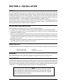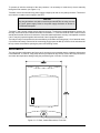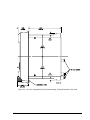
1
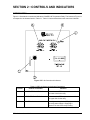
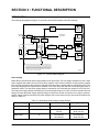
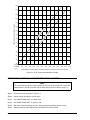
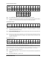
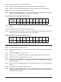
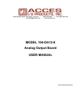
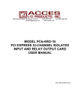
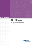
INSTRUCTION MANUAL
FOR
TEMPERATURE RELAY
BE1-49
Publication Number:
Revision:
9 1267 00 990
E
11/02
INTRODUCTION
This Instruction Manual provides information concerning the operation and installation of the BE1-49
Temperature Relay. To accomplish this, the following is provided.
# Specifications
# Functional characteristics
# Installation
# Operational Tests
# Mounting Information
WARNING!
To avoid personal injury or equipment damage, only qualified personnel
should perform the procedures presented in this manual.
BE1-49 Introduction
i
First Printing: 1980
Printed in USA
© 1980, 1998, 2001, 2002 Basler Electric, Highland, IL 62249
November 2002
CONFIDENTIAL INFORMATION
OF BASLER ELECTRIC COMPANY, HIGHLAND, IL. IT IS LOANED FOR CONFIDENTIAL USE, SUBJECT
TO RETURN ON REQUEST, AND WITH THE MUTUAL UNDERSTANDING THAT IT WILL NOT BE USED IN
ANY MANNER DETRIMENTAL TO THE INTEREST OF BASLER ELECTRIC COMPANY.
It is not the intention of this manual to cover all details and variations in equipment, nor does
this manual provide data for every possible contingency regarding installation or operation.
The availability and design of all features and options are subject to modification without
notice. Should further information be required, contact Basler Electric Company, Highland,
Illinois.
BASLER ELECTRIC
ROUTE 143, BOX 269
HIGHLAND, IL 62249 USA
http://www.basler.com, [email protected]
PHONE 618-654-2341
ii
FAX 618-654-2351
BE1- 49 Introduction
CONTENTS
SECTION 1
GENERAL INFORMATION . . . . . . . . . . . . . . . . . . . . . . . . . . . . . . . . . . . . . . . . . 1-1
GENERAL . . . . . . . . . . . . . . . . . . . . . . . . . . . . . . . . . . . . . . . . . . . . . . . . . . . . . . .
DESCRIPTION . . . . . . . . . . . . . . . . . . . . . . . . . . . . . . . . . . . . . . . . . . . . . . . . . . .
MODEL AND STYLE NUMBER . . . . . . . . . . . . . . . . . . . . . . . . . . . . . . . . . . . . . .
SAMPLE STYLE NUMBER . . . . . . . . . . . . . . . . . . . . . . . . . . . . . . . . . . . . . . . . . .
SPECIFICATIONS . . . . . . . . . . . . . . . . . . . . . . . . . . . . . . . . . . . . . . . . . . . . . . . .
SECTION 2
1-1
1-1
1-1
1-3
1-4
CONTROLS AND INDICATORS . . . . . . . . . . . . . . . . . . . . . . . . . . . . . . . . . . . . . 2-1
INTRODUCTION . . . . . . . . . . . . . . . . . . . . . . . . . . . . . . . . . . . . . . . . . . . . . . . . . . 2-1
SECTION 3
FUNCTIONAL DESCRIPTION . . . . . . . . . . . . . . . . . . . . . . . . . . . . . . . . . . . . . . . 3-1
INTRODUCTION . . . . . . . . . . . . . . . . . . . . . . . . . . . . . . . . . . . . . . . . . . . . . . . . . .
Power Supply . . . . . . . . . . . . . . . . . . . . . . . . . . . . . . . . . . . . . . . . . . . . . . . . .
Power Supply Status Output (Option 2-S) . . . . . . . . . . . . . . . . . . . . . . . . . . .
Constant Current Source . . . . . . . . . . . . . . . . . . . . . . . . . . . . . . . . . . . . . . . .
Amplifier . . . . . . . . . . . . . . . . . . . . . . . . . . . . . . . . . . . . . . . . . . . . . . . . . . . . .
Reference Voltage Supply . . . . . . . . . . . . . . . . . . . . . . . . . . . . . . . . . . . . . . .
Upper and Lower Temperature Comparators . . . . . . . . . . . . . . . . . . . . . . . . .
Latch (Optional) . . . . . . . . . . . . . . . . . . . . . . . . . . . . . . . . . . . . . . . . . . . . . . .
Output Drivers . . . . . . . . . . . . . . . . . . . . . . . . . . . . . . . . . . . . . . . . . . . . . . . . .
Output Relay . . . . . . . . . . . . . . . . . . . . . . . . . . . . . . . . . . . . . . . . . . . . . . . . . .
Target Indicator . . . . . . . . . . . . . . . . . . . . . . . . . . . . . . . . . . . . . . . . . . . . . . . .
SECTION 4
INSTALLATION . . . . . . . . . . . . . . . . . . . . . . . . . . . . . . . . . . . . . . . . . . . . . . . . . . 4-1
GENERAL . . . . . . . . . . . . . . . . . . . . . . . . . . . . . . . . . . . . . . . . . . . . . . . . . . . . . . .
RELAY OPERATING PRECAUTIONS . . . . . . . . . . . . . . . . . . . . . . . . . . . . . . . . .
DIELECTRIC TEST . . . . . . . . . . . . . . . . . . . . . . . . . . . . . . . . . . . . . . . . . . . . . . . .
MOUNTING . . . . . . . . . . . . . . . . . . . . . . . . . . . . . . . . . . . . . . . . . . . . . . . . . . . . . .
CONNECTIONS . . . . . . . . . . . . . . . . . . . . . . . . . . . . . . . . . . . . . . . . . . . . . . . . . .
ADJUSTMENTS . . . . . . . . . . . . . . . . . . . . . . . . . . . . . . . . . . . . . . . . . . . . . . . . . .
SECTION 5
4-1
4-1
4-1
4-1
4-1
4-2
OPERATIONAL TEST . . . . . . . . . . . . . . . . . . . . . . . . . . . . . . . . . . . . . . . . . . . . . 5-1
INTRODUCTION . . . . . . . . . . . . . . . . . . . . . . . . . . . . . . . . . . . . . . . . . . . . . . . . . .
POWER SUPPLY STATUS OUTPUT (OPTION 2-S) . . . . . . . . . . . . . . . . . . . . . .
OPERATIONAL TEST OF UPPER TEMPERATURE LIMIT TRIP . . . . . . . . . . . .
OPERATIONAL TEST OF LOWER TEMPERATURE LIMIT TRIP . . . . . . . . . . . .
TRIP POINT SELECTION (EXCEPT OUTPUT OPTIONS L AND M) . . . . . . . . .
TRIP POINT SELECTION (OUTPUT OPTIONS L AND M) . . . . . . . . . . . . . . . . .
SECTION 6
3-1
3-1
3-2
3-2
3-2
3-2
3-2
3-2
3-3
3-3
3-3
5-1
5-1
5-1
5-4
5-5
5-6
MAINTENANCE . . . . . . . . . . . . . . . . . . . . . . . . . . . . . . . . . . . . . . . . . . . . . . . . . . 6-1
GENERAL . . . . . . . . . . . . . . . . . . . . . . . . . . . . . . . . . . . . . . . . . . . . . . . . . . . . . . . 6-1
STORAGE . . . . . . . . . . . . . . . . . . . . . . . . . . . . . . . . . . . . . . . . . . . . . . . . . . . . . . . 6-1
SECTION 7
MANUAL CHANGE INFORMATION . . . . . . . . . . . . . . . . . . . . . . . . . . . . . . . . . . 7-1
CHANGES . . . . . . . . . . . . . . . . . . . . . . . . . . . . . . . . . . . . . . . . . . . . . . . . . . . . . . . 7-1
BE1-49 Introduction
iii
This page intentionally left blank.
SECTION 1 • GENERAL INFORMATION
GENERAL
The BE1-49 Temperature Relay is a solid-state device that monitors the temperature of a remotely located
resistive temperature detector (RTD), and provides signals to the protective scheme when the sensed temperature
goes above or below predetermined limits. A variety of output options provide a selection of latching or nonlatching types of normally open or closed contacts.
DESCRIPTION
The Basler Temperature Relay supplies a constant current to a remotely located resistive temperature detector,
and senses the temperature of the detector by measuring the voltage across the resistive element. When a preprogrammed temperature limit is reached, the relay energizes its output relay so that the protection scheme may
take appropriate action.
Programming of the temperature limits is accomplished by adjusting the UPPER TEMPERATURE LIMIT and
LOWER TEMPERATURE LIMIT controls on the relay front panel. Each control is adjustable over a range of 60°
to 190°C. The effect on the protection scheme of exceeding the control setting limits of the relay is defined by the
output option selected. Table 1-1 shows the available output options. The dotted horizontal lines represent
hypothetical upper and lower temperature limit settings. The circled numbers represent relay case terminals.
A target that indicates when the upper temperature limit has been exceeded is optionally available, and may be
either internally operated or current operated. The current operated target requires a minimum of 0.1 A to flow in
the trip circuit for proper operation. The internally controlled target MUST be specified if NC output contacts are
specified.
The relay assembly is mounted in a drawout cradle and enclosed in a standard, utility style case. Individual circuit
components are accessible by removing the individual printed circuit boards from the relay cradle and using an
extender board (Basler part number 9 1655 00 100) to test or troubleshoot.
MODEL AND STYLE NUMBER
The electrical characteristics and optional features included in a particular model BE1-49 Temperature Relay are
defined by a combination of letters and numbers that make up its style number. The model number, followed by
its style number, appears on the front panel, drawout cradle, and inside the case assembly.
The style charts represented by Figure 1-1, lists all available options and relates them to the style number system.
Upon receipt of a temperature relay, be sure to check relay style number against the requisition and packing list
to see that they agree.
BE1-49 General Information
1-1
The call-outs in the following figure are referred to in Table 1-1.
Table 1-1. Output Characteristics
A
B
C
D
E
OPERATING POWER ON
Output Style
F. Two Relays,
NO
H. Two relays,
NC
J. Two relays, NO,
Latching (UTL)
L. One relay, NO,
Latching
M. One relay, NC,
Latching
N. Two relays:
Upper NO
Lower NC
P. Two relays:
Upper NC
Lower NO
R. Two relays,
NC, Latching
(UTL)
S. Two relays:
Upper NO
Latching
Lower NC
T. Two relays:
Upper NC
Latching
Lower NO
1-2
Operating power
off or operating
power on and
temperature is less
than LTL
Temperature
greater than LTL
but less than
UTL
Temperature
greater than
UTL
Temperature
drops below
UTL
Temperature
drops below
LTL
1
10
2
Open, Closed
Closed, Closed
Open, Closed
Open, Open
1
10
2
Closed, Open
Open, Open
Closed, Open
Closed, Closed
1
10
2
Open, Closed,
Closed, Closed
Closed, Closed
Open, Open
1
10
Open
Closed
Closed
Open
1
10
Closed
Open
Open
Closed
1
10
2
Open, Open
Closed, Open
Open, Open
Open, Closed
1
10
2
Closed, Closed
Open, Closed
Closed, Closed
Closed, Open
1
10
2
Closed, Open
Open, Open
Open, Open
Closed, Closed
1
10
2
Open, Open
Closed, Open
Closed, Open
Open, Closed
1
10
2
Closed, Closed
Open, Closed
Open, Closed
Closed, Open
BE1-49 General Information
SAMPLE STYLE NUMBER
The style number identification chart above illustrates the manner in which a relay's style number is determined.
For example, if the style number were P1J-A1E-B0N5F the device would have the following features.
(P)
(1)
(J)
(A1)
(E)
(B)
(0)
(N)
(5)
(F)
RTD sensing output
Designed to be used with copper RTD rated 10 ohms at 25°C
Two normally open primary outputs, with the upper temperature limit trip contact latching on closure
Instantaneous trip timing
Isolated internal operating power obtained from 100/120 Vac or 48/125 Vdc source
One current operated target
No Option 1 available
No Option 2 available
SPDT auxiliary contact output
Semi-flush mounting
Figure 1-1. Style Number Identification Chart
BE1-49 General Information
1-3
SPECIFICATIONS
Sensing Method
Four wire, using a remotely installed 10 ohm copper or
100 ohm platinum resistive temperature detector (RTD)
located within the protected machine. Relay supplies
constant 40 mA current and senses voltage across the
temperature sensitive resistance element.
Outputs
Output contacts are rated as follows.
Resistive
120/240 Vac - make 30 A for 0.2 seconds, carry 7 A
continuously, break 7 A. 250 Vdc - make and carry 30 A
for 0.2 seconds, carry 7 A continuously, break 0.1 A. 500
Vdc - make and carry 15 A for 0.2 seconds, carry 7 A
continuously, break 0.1 A.
Inductive
120/240 Vac, 125 Vdc, 250 Vdc - break 0.1 A (L/R = 0.04).
Power Supply
One of the six types of power supplies listed in Table 1-2
may be selected to provide internal relay operating power.
Table 1-2. Power Supply Types And Specifications
Type
Nominal Input
Voltage
Input Voltage
Range
Burden at
Nominal
B (Mid Range)
48 Vdc
24 to 150 Vdc
4.0 W
C (Mid Range)
125 Vdc
120 Vac
24 to 150 Vdc
90 to 132 Vac
4.5 W
10.3 VA
D (Low Range)
24 Vdc
12 to 32 Vdc t
4.0 W
E (Mid Range)
125 Vdc
120 Vac
24 to 150 Vdc †
90 to 132 Vac
4.5 W
10.3 VA
W (Mid Range)
48 Vdc
125 Vdc
24 to 150 Vdc
24 to 150 Vdc
4.0 W
4.5 W
X (High Range)
250 Vdc
240 Vac
62 to 280 Vdc
90 to 270 Vac
5.2 W
14.0 VA
t Type D power supply initially requires 14 Vdc to begin operating. Once operating,
the voltage may be reduced to 12 Vdc and operation will continue.
† Prior to 1996, Type E power supply accepted only ac input power. See the power
supply discussion in Section 3, Functional Description.
Target Indicator
1-4
A magnetically latched, manually reset, target indicator is
optionally available to indicate that the output has tripped.
An internally operated or current operated target may be
specified. A current operated target requires 0.2 A in the
output trip circuit to actuate, and trip circuit current must
not exceed 30 A for 0.2 seconds, 7 A for 2 minutes, and 3
A continuous. A current operated target may be selected
only when normally open (NO) output contacts have been
specified.
BE1-49 General Information
Temperature Adjustment Range
Two independently adjustable temperature controls, one
for upper and one for lower temperature limits, each
capable of settings over the range of 60 to 190°C.
Pickup Accuracy
Relay pickup point will not vary more than +3°C for
variations in input power or operating temperature within
the operating range.
UL
UL Recognized under Standard 508, UL File #E97033.
Shock
In standard tests, the relay has withstood 15 g in each of
three mutually perpendicular axes without structural
damage or degradation of performance.
Vibration
In standard tests, the relay has withstood 2 g in each of
three mutually perpendicular axes swept over the range of
10 to 500 Hz for a total of six sweeps, 15 minutes each
sweep, without structural damage or degradation of
performance.
Isolation
In accordance with IEC 255-5 and ANSI/IEEE C37.90, one
minute dielectric (high potential) tests as follows:
All circuits to ground:
Input to output circuits:
Surge Withstand Capability
2,121 Vdc
1,500 Vac or 2,121 Vdc.
Qualified to ANSI/IEEE C37.90.1 1989 (Transient Immunity
and Radiated Susceptibility).
Qualified to IEC-255-5 (Impulse requirements) and IEC-2555\6 (Surge requirements).
Temperature
Operating Range
Storage Range
–4°F to 149°F (–20°C to 65°C)
–58°F to 194°F (–50°C to 90°C)
Weight
11 lb (5 kg) net.
Case Size
S1 (See Section 4, Installation for dimensions.)
BE1-49 General Information
1-5
This page intentionally left blank.
SECTION 2 • CONTROLS AND INDICATORS
INTRODUCTION
Figure 2-1 illustrates the controls and indicators of the BE1-49 Temperature Relay. The locators of Figure 2-1
correspond to the locators listed in Table 2-1. Table 2-1 lists and describes each control and indicator.
Figure 1BE1-49 Controls and Indicators
Table 2-1. BE1-49 Control and Indicator Descriptions
Locator
Control or Indicator
Function
A
LOWER TEMP LIMIT °C Control
Determines the RTD temperature that will be
the lower limit for the relay.
B
UPPER TEMP LIMIT °C Control
Determines the RTD temperature that will be
the upper limit for the relay.
C
POWER Indicator
A red light emitting diode (LED) lights when
the relay power supply is supplying a
nominal +12 Vdc to the relay circuitry.
BE1-49 Controls and Indicators
2-1
Locator
2-2
Control or Indicator
Function
D
Target Indicator
An overtemperature condition, as set by the
UPPER TEMP LIMIT °C control, trips the
normally black target indicator to red. The
target is magnetically latched and may be
manually reset by the target reset lever after
the overtemperature indication is terminated.
Depending on the option supplied, the
temperature indication may be terminated
when the over temperature condition has
ended, or when the RTD temperature has
fallen below the lower temperature limit as
set by the LOWER TEMP LIMIT °C control
on relays with a latching type of output.
E
Target Reset Lever
The target indicator is a magnetically latched
device. Therefore, the target must be
returned to its normal (black) position after an
upper temperature indication is terminated by
pushing up on the reset lever that extends
through the lower left of the relay case front
cover.
BE1-49 Controls and Indicators
SECTION 3 • FUNCTIONAL DESCRIPTION
INTRODUCTION
The following paragraphs and Figure 3-1 provide a functional description of the BE1-49 relay.
Paddle Operated Shorting Bars
POWER
SUPPLY
SENSOR
11
12
POWER
SUPPLY
STATUS
17
POWER
SUPPLY
POWER 3
INPUT 4
OPERATING
VOLTAGE
CONSTANT
CURRENT
SOURCE
18
19
AUXILIARY
OUTPUTS
REFERENCE
VOLTAGE
SUPPLY
1
TGT
8
UPPER
TEMP.
LIMIT
9
R
T
D
1
UPPER
SET OPTIONAL
TEMPERATURE
LATCH
COMPARATOR
OUTPUT
DRIVER
(HIGH)
UPPER
TEMP.
OUTPUT
10
RESET
AMPLIFIER
2
7
LOWER
TEMP.
LIMIT
6
LOWER
TEMPERATURE
COMPARATOR
OUTPUT
DRIVER
(LOW)
10
LOWER
TEMP.
OUTPUT
1
THE BE1-49 TEMPERATURE RELAY REQUIRES FOUR WIRES FOR THE
RTD. ONE PAIR PROVIDES CONSTANT CURRENT AND THE SECOND
PAIR MONITORS THE RTD VOLTAGE DROP. THIS CONFIGURATION
ELIMINATES MATCHING THE RESISTANCE OF THE LEADS. NO
BALANCING OF LEAD RESISTANCE OR REGARD FOR WIRE LENGTH IS
NECESSARY AS LONG AS THE TOTAL RESISTANCE OF THE WIRING IN
THE RTD CIRCUIT IS LESS THAN 20 OHMS.
D2817-08
07-09-98
Figure 3-1. Functional Block Diagram
Power Supply
Basler Electric enhanced the power supply design for unit case relays. The new design created three, wide- range
power supplies that replace the six previous power supplies. Style number identifiers for these power supplies
have not been changed so that customers may order the same style numbers that they ordered previously. The
first newly designed power supplies were installed in unit case relays with EIA date codes 9638 (third week of
September 1996). The new power supply design is indicated by a circuit board part number of 9 2757 XX XXX.
The older power supply design is indicated by a circuit board part number of 9 1431 XX XXX. A benefit of the new
design increases the power supply operating ranges such that the 48/125 volt selector is no longer necessary.
Specific voltage ranges for the three new power supplies and a cross reference to the style number identifiers are
shown in Table 3-1.
Table 3-1. Wide Range Power Supply Voltage Ranges
Power Supply
Style Chart Identifiers
Nominal Voltage
Voltage Range
Low Range
D
24 Vdc
12 t to 32 Vdc
Mid Range
B, C, E, W
48, 125 Vdc,
120 Vac
24 to 150 Vdc,
90 to 132 Vac
High Range
X
125, 250 Vdc,
120, 240 Vac
t 14 Vdc is required to start the power supply.
62 to 280 Vdc,
90 to 270 Vac
BE1-49 Functional Description
3-1
Relay operating power is developed by the wide-range, isolated, low burden, fly-back switching power supply.
Nominal ±12 Vdc is delivered to the relay internal circuitry. Input (source voltage) for the power supply is not
polarity sensitive. A red LED lights to indicate that the power supply is functioning properly.
NOTE
If a relay has an older power supply (as indicated above), the RTD measuring
circuit is not isolated from relay input power terminals 3 and 4. If the RTDs are
grounded and the relay power supply is the old style, only a Type E power supply
may be used. Old style Type E power supplies included an isolation transformer
that permitted the RTDs to be grounded. Old style power supplies accepted only
ac input power; new style power supplies accept both ac and dc input power.
Power Supply Status Output (Option 2-S)
The power supply status output relay is energized and its NC output contact is opened when power is applied to
the relay. Normal internal relay operating voltage maintains the power supply status output relay continuously
energized with its output contact open. If the power supply output voltage falls below the requirements of proper
operation, the power supply output relay is de-energized, closing the NC output contact.
Constant Current Source
The constant current source provides a regulated 40 mA to the external RTD. This circuit is relatively unaffected
by changes in the ambient temperature. Since resistance of the RTD varies directly with temperature, 40 mA
through the RTD develops a voltage which is proportional to RTD temperature. See Section 5 for a graphical
representation.
Amplifier
The amplifier monitors the voltage across the RTD and provides a voltage level signal to both the upper and lower
temperature limit comparator stages.
Reference Voltage Supply
The reference voltage supply provides a regulated voltage to the UPPER TEMPERATURE LIMIT and LOWER
TEMPERATURE LIMIT front panel controls. Each of these controls is a potentiometer and functions as a variable
voltage divider. The position of the potentiometer wiper determines a reference voltage for one input of the
corresponding comparator circuit.
Upper And Lower Temperature Comparators
Two similar comparators in the relay each compare the amplified voltage across the RTD with a dedicated
reference voltage established by the setting of a front panel control. The upper temperature comparator provides
an output current to its associated driver circuit when the RTD voltage exceeds the reference voltage from the
UPPER TEMPERATURE LIMIT potentiometer. The lower temperature comparator provides an output current to
its associated driver circuit when the RTD voltage is less than the reference voltage from the LOWER
TEMPERATURE LIMIT potentiometer.
Latch (Optional)
A latching function is optionally available for the upper temperature output. When this latch is selected, the upper
temperature output will latch in its energized condition when the upper temperature limit is exceeded. The output
will then remain latched until the RTD temperature falls below its lower limit (as determined by the lower
temperature comparator).
3-2
BE1-49 Functional Description
Output Drivers
Two Darlington amplifiers are provided as output drivers in the relay. Each amplifier receives the output current
from an associated comparator and amplifies it to provide sufficient current to drive the selected output device.
An inverter is provided in the input to the lower limit output driver to cause it to energize the output relay when the
lower limit is exceeded.
Output Relay
A wide variety of relay contact arrangements are available. The contact arrangement is specified by the OUTPUT
letter in the relay style number. Refer to Figure 1-1 for a list of all of the available output options.
Target Indicator
An optional target indicator on the front panel is tripped and magnetically latched when the upper temperature limit
is exceeded. It may be reset manually after the upper temperature limit output is de-energized.
BE1-49 Functional Description
3-3
This page intentionally left blank.
SECTION 4 • INSTALLATION
GENERAL
When not shipped as part of a control or switchgear panel, the relays are shipped in sturdy cartons to prevent
damage during transit. Immediately upon receipt of a relay, check the model and style number against the
requisition and packing list to see that they agree. Visually inspect the relay for damage that may have
occurred during shipment. If there is evident damage, immediately file a claim with the carrier and notify the
Regional Sales Office, or contact Customer Service at Basler Electric, Highland, Illinois.
In the event the relay is not to be installed immediately, store the relay in its original shipping carton in a
moisture and dust free environment. When the relay is to be placed in service, it is recommended that the
following operational test be performed prior to installation.
RELAY OPERATING PRECAUTIONS
Before installation or operation of the relay, note the following precautions:
1. A minimum of 0.2 A in the output circuit is required to ensure operation of current operated targets.
2. The relay is a solid-state device. If a wiring insulation test is required, remove the connecting plugs and
withdraw the cradle from its case.
3. When the connecting plugs are removed the relay is disconnected from the operating circuit and will not
provide system protection. Always be sure that external operating (monitored) conditions are stable before
removing a relay for inspection, test, or service. Also, be sure that connecting plugs are in place before
replacing the front cover.
4. Be sure the relay case is hard wired to earth ground using the ground terminal on the rear of the unit. Use
a separate ground lead to the ground bus for each relay.
DIELECTRIC TEST
In accordance with IEC 255-5 and ANSI/IEEE C37.90, one minute dielectric (high potential) tests as follows:
All circuits to ground:
Input to output circuits:
2,121 Vdc
1,500 Vac or 2,121 Vdc.
MOUNTING
Relay outline dimensions and panel drilling diagrams are supplied in Figures 4-1 through 4-10.
CONNECTIONS
Incorrect wiring may result in damage to the relay. Be sure to check model and style number against the
options listed in the Style Number Identification Chart before connecting and energizing a particular relay.
Connections should be made with 14 AWG stranded wire or better. Typical external connections are shown
in Figure 4-11 . For internal connections refer to Section 3, Functional Description.
NOTE
Be sure the relay case is hard-wired to earth ground with no smaller than 12 AWG
copper wire attached to the ground terminal on the rear of the relay case. When the
relay is configured in a system with other protective devices, always use a separate
lead to the ground bus from each relay.
BE1-49 Installation
4-1
To prevent an inductive overload of the relay contacts, it is necessary to break the trip circuit externally
through the 52a contacts. (see Figure 4-11).
Terminals 3 and 4 are external relay power supply voltage inputs and are not polarity sensitive. Terminals 6
and 8 are the constant current supply to the RTD.
CAUTION
If a relay built before mid 1996 is used with grounded RTDs, the relay must use
a Type E power supply. Refer to the power supply discussion in Section 3,
Functional Description.
Terminals 7 and 9 are the voltage sensing inputs to the relay. To achieve the rated temperature accuracy for
the relay, a wire should be connected from each of terminals 6, 7, 8, and 9 to the RTD. Each of the four wires
should have less than 20 ohms of resistance. If less than rated temperature accuracy is acceptable, terminals
6 and 7 may be jumpered together and terminals 8 and 9 jumpered together.
The relay circuitry is connected to the case terminals by removable connecting plugs (1 for 10 terminal cases,
2 for 20 terminal cases). Removal of the connecting plug(s) opens the NO trip contact circuit and shorts the
NC trip contact circuit before opening the power and sensing circuits.
ADJUSTMENTS
The relay has been calibrated at the factory and it is strongly recommended that the calibration adjustments
not be disturbed. If, however, relay pickup accuracy is suspect for any reason, remove the relay from service
and check the temperature settings using the procedures given in Section 5 of this manual.
D1427-01.VSD
12-04-01
Figure 4-1. S1 Case, Outline Dimensions, Front View
4-2
BE1-49 Installation
D2856-23
06-15-99
Figure 4-2 . S1 Case, Single-Ended, Semi-Flush Mounting, Outline Dimensions, Side View
BE1-49 Installation
4-3
CASE
DETAIL A-A
SHOWING THE ADDITION OF WA
OVER THE BOSS TO TIGHTEN
RELAY AGAINST THE PANE
D1427-28
12-04-01
Figure 4-3 . S1 Case, Single-Ended, Projection Mount, Outline Dimensions, Side View
4-4
BE1-49 Installation
D1427-27
12-04-01
Figure 4-4 . S1 Case, Double-Ended, Semi-Flush Mounting,
Outline Dimensions, Side View
BE1-49 Installation
4-5
CASE
DETAIL A-A
SHOWING THE ADDITION OF WASH
OVER THE BOSS TO TIGHTEN T
RELAY AGAINST THE PANEL
P0002-17
01-30-01
Figure 4-5 . S1 Case, Double-Ended, Projection Mount, Outline Dimensions, Side View
4-6
BE1-49 Installation
5.56
(141.3)
D1427-25
12-06-01
8.38
(212.9)
9
10
1
2
Figure 4-6 . S1 Case, Single-Ended, Projection Mount,
Outline Dimensions, Rear View
BE1-49 Installation
4-7
5.56
(141.3)
D142702
7-993
19
20
11
12
8.68
(220.7)
9
10
1
2
Figure 4-7. S1 Case, Double-Ended, Projection Mount,
Outline Dimensions, Rear View
4-8
BE1-49 Installation
Figure 4-8 . S1 Case, Panel Drilling Diagram, Semi-Flush Mounting
BE1-49 Installation
4-9
Figure 4-9 . S1 Case, Single-Ended, Projection Mount,
Panel Drilling Diagram, Rear View
4-10
BE1-49 Installation
Figure 4-10 . S1 Case, Double-Ended, Projection Mounting,
Panel Drilling Diagram, Rear View
BE1-49 Installation
4-11
Figure 4-11. DC Connection Diagram
4-12
BE1-49 Installation
SECTION 5 • OPERATIONAL TEST
INTRODUCTION
Operational test procedures are provided in this section for use in verifying operation of the temperature relay
and for selecting desired upper and lower temperature limit trip points. Temperature calibrations performed
on the bench may be affected by the resistance of the relay-to-RTD wiring in the field installation. This effect
is minimized by using the 4-wire sensing connection shown in Figure 4-11. These variations will be on the
order of 1.5°C or less, provided the field wiring is held at 20 ohms or less per lead. For greater accuracy, it
is suggested that a resistance equivalent to that of the RTD current supply wiring be inserted in the test setup.
If a relay fails an operational test, refer to Section 6. Alternatively, the relay may be returned to the factory for
repair. When returning the relay to the factory, ship the entire relay cradle assembly, preferably in the case.
Some of the steps in the following procedures call for observations that are dependent on the output option
supplied. A table of observable results is provided with those steps.
CAUTION
Before performing the following tests, refer to the relay operating precautions in
Section 4, Installation.
POWER SUPPLY STATUS OUTPUT (OPTION 2-S)
Step 1. With the unit in a powered-up condition, verify that the power supply status output contact is
energized open (terminals 11 and 12).
Step 2. Remove input power and verify that the status output contact closes. Restore input power.
OPERATIONAL TEST OF UPPER TEMPERATURE LIMIT TRIP
Step 1. Connect the relay as shown in Figure 5-1.
Step 2. Set the resistor decade box for minimum resistance.
Step 3. Set LOWER TEMP LIMIT °C control to 60.
Step 4. Set UPPER TEMP LIMIT °C control to 190.
Step 5. With relay connecting plug(s) in place, apply appropriate operating power to relay.
Step 6. Observe that the test setup indicators are ON or OFF as listed in the chart which follows.
Test Setup Indicators, Step 6
OUTPUT
OPTION
C
D
F
H
J
L
M
N
P
R
S
T
ON
OFF
ON
ON
OFF
ON
OFF
ON
ON
OFF
DS1
OFF OFF OFF
ON
OFF OFF
DS2
OFF OFF OFF
ON
OFF
-
-
ON
OPTION 3
0
1
2
5
DS3
---
---
ON
ON
DS4
---
OFF
---
OFF
BE1-49 Operational Test
5-1
DS3
DS4
4
19
17
18
UPPER
TEMP. TRIP
CIRCUIT
AUXILIARY
CONTACTS
LOWER
TEMP. TRIP
CIRCUIT
2
RTD
CURRENT
SOURCE
POWER
SUPPLY
TEMP.
SENSING
RTD
SENSE
1
9
10
7
8
5
6
3
1
4
2
}
D.C. +
DS2
3
APPROPRIATE AC OR
DC POWER SOURCE
7
6
5
RESISTOR
DECADE
BOX
8
D2817-10
07-09-98
DS1
1
Relay ground stud.
2
Not present in Options L and M.
3
DC source supplies a maximum of 250 Vdc.
4
DS3 and DS4 not required when Option 3 is 0. DS3 required when
Option 3 is 2. DS4 required when Option 3 is 1 or 3.
5
1/4 W Resistor is 10 ohms for copper RTD, 100 ohms for platinum.
6
If relay has current operated target, obtain minimum trip current by adding
parallel resistance to DS1 and DS2.
Omit DS2 when testing relays equipped with output options L or M.
7
8
Figure 5-1. Temperature Relay Test Setup
5-2
Range of decade box is zero to 10 ohms for copper RTD; zero to
100 ohms for platinum.
BE1-49 Operational Test
Step 7. Set UPPER TEMP LIMIT °C control to the upper temperature limit to be tested.
Step 8.
Adjust resistor decade box for greater resistance until an upper temperature limit trip indication (DS1)
is observed. The chart below presents the trip indication for all relay output options. On relays with
target option A, target will also indicate trip. On relays with target option B, target will indicate trip if
current through terminal 1 is at least 0.2 A.
Trip Indications, Step 8
OUTPUT
OPTION
C
D
F
DS1
ON
ON
ON
H
J
OFF ON
L
ON
M
N
OFF ON
OPTION 3
0
1
2
5
DS3
---
---
OF
F
OF
F
DS4
---
ON
---
ON
P
R
S
OFF OFF ON
T
OFF
Step 9. Read resistance from decade box. Refer to Figure 5-2, Temperature/Resistance, to verify the
temperature at which the trip occurred.
Step 10. Adjust UPPER TEMP LIMIT °C as necessary and repeat steps 8 and 9 until upper temperature limit
trip occurs at desired temperature.
Step 11. On relays with output options J, L, M, R, S, and T, adjust resistor decade box for 0.96 ohms. For all
other relays determine the resistance that corresponds to a level 10°C below the upper limit setting
(using Figure 5-2), then adjust resistor decade box for the resistance value obtained. Observe that
relay resets per indication chart below.
Reset Indications, Step 11
OUTPUT
OPTION
DS1
C
D
F
OFF OFF OFF
BE1-49 Operational Test
H
ON
J
L
M
OFF OFF ON
N
P
R
S
T
OFF
ON
ON
OFF
ON
OPTION 3
0
1
2
5
DS3
---
---
ON
ON
5-3
180
170
160
150
R)
130
90
(1
0
PL
AT
IN
UM
100
0O
R
110
HM
(1
0
+
R)
OH
M
+
120
CO
PP
E
TEMPERATURE IN DEGREES CELSIUS
140
80
70
60
50
40
COPPER
1.0
1.5
2.0
2.5
3.0
3.5
4.0
4.5
5.0
5.5
6.0
6.5
7.0
PLATINUM
10.0
15.0
20.0
25.0
30.0
35.0
40.0
45.0
50.0
55.0
60.0
65.0
70.0
D2817-12
07-07-98
RESISTANCE (IN OHMS) ABOVE 10 OHMS (COPPER), OR ABOVE 100 OHMS (PLATINUM)
Figure 5-2. RTD Temperature/Resistance Graph
OPERATIONAL TEST OF LOWER TEMPERATURE LIMIT TRIP
NOTE
The operational test for the lower temperature limit trip is not required on relays with
output options L and M. (The lower trip on these relays is given in Step 3, page 5-1.)
Step 1. Connect the relay as shown in Figure 5-1.
Step 2. Set the resistor decade box for 0.0 ohms.
Step 3. Set LOWER TEMP LIMIT °C control to 60.
Step 4. Set UPPER TEMP LIMIT °C control to 190.
Step 5. With relay connecting plug(s) in place, apply appropriate operating power to relay.
Step 6. Observe states of test setup indicators as listed in the following chart.
5-4
BE1-49 Operational Test
Test Setup Indicators, Step 6
OUTPUT
OPTION
C
D
F
H
J
L
M
N
P
R
S
T
ON
OFF
ON
ON
OFF
ON
OFF
ON
ON
OFF
DS1
OFF OFF OFF
ON
OFF OFF
DS2
OFF OFF OFF
ON
OFF
-
-
ON
OPTION 3
0
1
2
5
DS3
---
---
ON
ON
DS4
---
OFF
---
OFF
Step 7. Set LOWER TEMP LIMIT °C control to the lower temperature limit to be tested.
Step 8. Gradually increase the decade box resistance until a lower temperature limit trip indication (DS2) is
observed. The chart below presents the trip indications for all relay output options.
Trip Indications, Step 8
OUTPUT
OPTION
C
D
F
DS2
ON
ON
ON
H
J
OFF ON
L
M
N
P
R
S
T
-
-
OFF
ON
ON
OFF
ON
Step 9. Read resistance from decade box. Refer to Figure 5-2, Temperature/ Resistance, to verify the
temperature at which the trip occurred.
Step 10. Adjust LOWER TEMP LIMIT °C as necessary and repeat steps 8 and 9 until lower temperature limit
trip occurs at desired temperature.
Step 11. Determine the resistance that corresponds to a level 10°C below the lower limit setting from Figure
5-2, then adjust resistor decade box for resistance value obtained. Observe relay resets by the
indication in chart below.
Reset Indication, Step 11
OUTPUT
OPTION
DS2
C
D
F
OFF OFF OFF
H
J
L
M
N
P
R
S
T
ON
OFF
-
-
ON
OFF
ON
ON
OFF
TRIP POINT SELECTION (EXCEPT OUTPUT OPTIONS L and M)
This procedure provides a method for selecting the upper and lower temperature limit trip points. The lower
trip point is selected first. If only the upper trip selection is desired, perform steps 1, 3, 9, 10 and 11.
Step 1. Connect the relay as shown in Figure 5-1.
Step 2. Set the LOWER TEMP LIMIT °C control to at least 10°C above the intended lower temperature limit
trip point.
Step 3. Set UPPER TEMP LIMIT °C control to 190.
BE1-49 Operational Test
5-5
Step 4. Set resistor decade box for minimum resistance.
Step 5. With relay connecting plug(s) in place, apply appropriate operating power to relay.
Step 6. Refer to Figure 5-2, Temperature/Resistance, to obtain resistance value for lower trip point.
Step 7. Set decade box for resistance value obtained in step 6.
Step 8. Slowly adjust LOWER TEMP LIMIT °C control counter-clockwise until trip indication in chart below
is observed. The lower temperature limit trip point is now selected.
Lower Temperature Limit Trip Point Selection, Step 8
OUTPUT
OPTION
C
D
F
H
J
N
P
DS1
ON
ON
ON
OFF
ON
OFF
ON
R
S
T
OFF OFF ON
Step 9. Refer to Figure 5-2, Temperature/Resistance to obtain resistance value for upper temperature limit
trip point.
Step 10. Set resistor decade box for resistance obtained in Step 9.
Step 11. Slowly adjust UPPER TEMP LIMIT °C control counter-clockwise until trip indication in chart below
is observed. The upper temperature limit trip point is now selected.
Upper Temperature Limit Trip Point Selection, Step 11
OUTPUT
OPTION
C
D
F
H
J
N
DS1
ON
ON
ON
OFF
ON
ON
P
R
OFF OFF
S
T
ON
OFF
TRIP POINT SELECTION (OUTPUT OPTIONS L AND M)
Step 1. Connect the relay as shown in Figure 5-1.
Step 2. Set the UPPER TEMP LIMIT °C control to at least 5°C above the intended upper temperature limit
trip point.
Step 3. Set LOWER TEMP LIMIT °C control to 60.
Step 4. Refer to Figure 5-2, Temperature/Resistance, to obtain resistance value for upper trip point.
Step 5. Set decade box for the resistance obtained in step 4.
Step 6. Slowly adjust UPPER TEMP LIMIT °C control counter-clockwise until appropriate trip is observed.
For option L, DS1 should go on; for option M, DS1 should go off. The upper temperature limit trip
point is now selected.
Step 7. Refer to Figure 5-2, Temperature/Resistance, to obtain resistance value for lower temperature limit
trip point.
Step 8. Set decade box for resistance obtained in step 7.
Step 9. Slowly adjust LOWER TEMP LIMIT °C control counterclockwise until appropriate indication is
observed. For option L, DS1 should go off; for option M, DS1 should go on. The lower temperature
limit trip point is now selected.
5-6
BE1-49 Operational Test
SECTION 6 • MAINTENANCE
GENERAL
Basler relays are static devices which require no preventive maintenance other than a periodic operational
check. The operational test procedure of Section 5 provides an adequate check to verify proper operation of
the relay.
If the relay fails to function properly, contact the Technical Support Services Department of Basler Electric for
a return authorization number before returning the relay for service.
STORAGE
This protective relay contains aluminum electrolytic capacitors which generally have a life expectancy in
excess of 10 years at storage temperatures less than 40°C. Typically, the life expectancy of an electrolytic
capacitor is cut in half for every 10°C rise in temperature. Storage life can be extended if, at one year intervals,
power is applied to the relay for a period of 30 minutes.
BE1-49 Maintenance
6-1
This page intentionally left blank.
SECTION 7 • MANUAL CHANGE INFORMATION
CHANGES
This section contains information concerning changes to current and previous editions of the manual. The
substantive changes are summarized in Table 7-1.
Table 7-1. Instruction Manual Revisions
Revision
Change
ECO/Date
C
Deleted reference to Service Manual 9 1267 00 620. Updated the
Dielectric Test information. Changed Input Voltage Range and Burden
Data in Power supply table in Specifications, Section 1. Corrected
Style Chart by changing power supply type X from “230 Vac” to “240
Vac”. Added new power supply information to Section 3 in Power
Supply paragraph starting with “Basler Electric enhanced the power
supply design...”. Added new dimension figures to include all options
available (S1 Single-Ended and Double-Ended, and both mounting
positions). Added power supply status and terminal connections to
Connection Diagram. Changed the symbol for case ground in Figure
5-1. Changed the format of the manual.
16871/07-98
D
Updated the figures in Section 4 to reflect new covers. Corrected error
in Figure 1-1: option 3 choices were changed from 0, 1, 2, and 3 to 0,
1, 2, and 5.
15559/12-01
E
Additions to the manual clarified that pre-1996 relays with Type E
power supplies and all post-1996 relays are compatible with grounded
RTDs.
19417/11-02
BE1-49 Manual Change Information
7-1
This page intentionally left blank.
ROUTE 143, BOX 269
HIGHLAND, IL 62249 USA
http://www.basler.com, [email protected]
PHONE +1 618-654-2341
FAX +1 618-654-2351