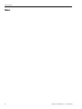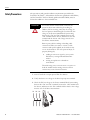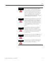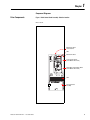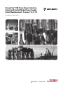
1
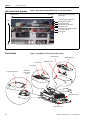
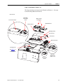
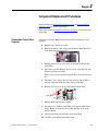
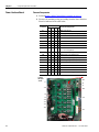
PowerFlex® 700 Drive Power Interface
Board and Switch Mode Power Supply
Board Replacement - Frames 7, 8, 9, 10
Installation Instructions
Important User Information
Solid state equipment has operational characteristics differing from those of electromechanical equipment. Safety
Guidelines for the Application, Installation and Maintenance of Solid State Controls (publication SGI-1.1 available
from your local Rockwell Automation sales office or online at http://literature.rockwellautomation.com) describes
some important differences between solid state equipment and hard-wired electromechanical devices. Because of
this difference, and also because of the wide variety of uses for solid state equipment, all persons responsible for
applying this equipment must satisfy themselves that each intended application of this equipment is acceptable.
In no event will Rockwell Automation, Inc. be responsible or liable for indirect or consequential damages resulting
from the use or application of this equipment.
The examples and diagrams in this manual are included solely for illustrative purposes. Because of the many
variables and requirements associated with any particular installation, Rockwell Automation, Inc. cannot assume
responsibility or liability for actual use based on the examples and diagrams.
No patent liability is assumed by Rockwell Automation, Inc. with respect to use of information, circuits, equipment,
or software described in this manual.
Reproduction of the contents of this manual, in whole or in part, without written permission of Rockwell
Automation, Inc., is prohibited.
Throughout this manual, when necessary, we use notes to make you aware of safety considerations.
WARNING
Identifies information about practices or circumstances that can cause an explosion in a hazardous environment,
which may lead to personal injury or death, property damage, or economic loss.
IMPORTANT
Identifies information that is critical for successful application and understanding of the product.
ATTENTION
Identifies information about practices or circumstances that can lead to personal injury or death, property damage, or
economic loss. Attentions help you identify a hazard, avoid a hazard, and recognize the consequence.
SHOCK HAZARD
Labels may be on or inside the equipment, for example, a drive or motor, to alert people that dangerous voltage may
be present.
BURN HAZARD
Labels may be on or inside the equipment, for example, a drive or motor, to alert people that surfaces may reach
dangerous temperatures.
Allen-Bradley, PowerFlex, TechConnect, and Rockwell Automation are trademarks of Rockwell Automation, Inc.
Trademarks not belonging to Rockwell Automation are property of their respective companies.
Table of Contents
Preface
Introduction . . . . . . . . . . . . . . . . . . . . . . . . . . . . . . . . . . . . . . . . . . . . . . .
Recommended Tools. . . . . . . . . . . . . . . . . . . . . . . . . . . . . . . . . . . . . . . .
Safety Precautions . . . . . . . . . . . . . . . . . . . . . . . . . . . . . . . . . . . . . . . . . .
Important Initial Steps. . . . . . . . . . . . . . . . . . . . . . . . . . . . . . . . . . . . . . .
5
5
6
8
Chapter 1
Component Diagrams
Drive Components . . . . . . . . . . . . . . . . . . . . . . . . . . . . . . . . . . . . . . . . . 9
Main Control Panel Assembly. . . . . . . . . . . . . . . . . . . . . . . . . . . . . . . . 10
Circuit Boards . . . . . . . . . . . . . . . . . . . . . . . . . . . . . . . . . . . . . . . . . . . . 10
Chapter 2
Component Replacement
Procedures
Publication 20B-IN22B-EN-P — December 2009
Remove Main Control Panel Assembly . . . . . . . . . . . . . . . . . . . . . . . .
Power Interface Board . . . . . . . . . . . . . . . . . . . . . . . . . . . . . . . . . . . . .
Remove Components . . . . . . . . . . . . . . . . . . . . . . . . . . . . . . . . . . .
Install Components . . . . . . . . . . . . . . . . . . . . . . . . . . . . . . . . . . . . .
Switch Mode Power Supply Board . . . . . . . . . . . . . . . . . . . . . . . . . . . .
Remove Components . . . . . . . . . . . . . . . . . . . . . . . . . . . . . . . . . . .
Install Components . . . . . . . . . . . . . . . . . . . . . . . . . . . . . . . . . . . . .
13
14
14
15
16
16
16
3
Table of Contents
Notes:
4
Publication 20B-IN22B-EN-P — December 2009
Preface
Introduction
This publication provides guidelines for replacing/installing Power Interface
Boards and Switch Mode Power Supply Boards in the PowerFlex 700 drive for
Frames 7, 8, 9, and 10. All kits include the board, wrist strap and hardware (if
required).
Description
Power Interface Board
Kit Catalog No.
SK-G9-GDB1-D292
SK-G9-GDB1-D325
SK-G9-GDB1-D365
SK-G9-GDB1-D415
SK-G9-GDB1-D481
SK-G9-GDB1-D535
SK-G9-GDB1-D600
SK-G9-GDB1-D700
SK-G9-GDB1-D875
Switch Mode Power Supply Board SK-G9-PWRS1-D0
Notes
292A Drives
325A Drives
365A Drives
415A Drives
481A Drives
535A Drives
600A Drives
730A Drives
875A Drives
7
X
X
Frame
8
9
10
X
X
X
X
X
X
X
X
X
X
X
The precautions and general installation requirements provided in the
PowerFlex 700 Frame 7-10 Installation Instructions (publication 20B-IN014)
and the PowerFlex 700 User Manual (publication 20B-UM002) must be
followed in addition to those included here.
Recommended Tools
The following list of tools is provided for your reference to disassemble and
assemble the drive and components. This list may not be all-encompassing for
your situation. Not all tools are needed for some components. Refer to
pertinent sections for details.
•
•
•
•
•
Publication 20B-IN22B-EN-P — December 2009
Screwdrivers (standard, Phillips, star – various sizes)
Socket set, metric
Cylindrical pick-up magnet
Pliers, needle-nose
Nylon tie wraps
5
Preface
Safety Precautions
The precautions and general installation requirements provided in the
PowerFlex 700 Frame 7-10 Installation Instructions (publication 20B-IN014)
and the PowerFlex 700 User Manual (publication 20B-UM002) must be
followed in addition to those included here.
To avoid an electric shock hazard, ensure that all
power has been removed before proceeding. In
addition, before servicing, verify that the voltage on
the bus capacitors has discharged. Check the DC bus
voltage at the Power Terminal Block by measuring
between the +DC and -DC terminals, between the
+DC terminal and the chassis, and between the -DC
terminal and the chassis. The voltage must be zero
for all three measurements.
ATTENTION
Remove power before making or breaking cable
connections. When you remove or insert a cable
connector with power applied, an electrical arc may
occur. An electrical arc can cause personal injury or
property damage by:
•
sending an erroneous signal to your system’s
field devices, causing unintended machine
motion.
• causing an explosion in a hazardous
environment.
Electrical arcing causes excessive wear to contacts on
both the module and its mating connector. Worn
contacts may create electrical resistance.
1. Turn off and lock out input power. Wait five minutes.
2. Verify that there is no voltage at the drive’s input power terminals.
3. Check the DC bus voltage at the Power Terminal Block by measuring
between the +DC and –DC terminals, between the +DC terminal and
the chassis, and between the –DC terminal and the chassis. The voltage
must be zero for all three measurements.
L1
L2
L3
I
O
6
Publication 20B-IN22B-EN-P — December 2009
Preface
ATTENTION
ATTENTION
ATTENTION
ATTENTION
ATTENTION
Publication 20B-IN22B-EN-P — December 2009
This assembly contains parts and sub-assemblies
that are sensitive to electrostatic discharge. Static
control precautions are required when servicing this
assembly. Component damage may result if you
ignore electrostatic discharge control procedures. If
you are not familiar with static control procedures,
reference Allen-Bradley Publication 8000-4.5.2
Guarding Against Electrostatic Damage, or any other
applicable ESD protection handbook.
The information in this publication is merely a guide
for proper installation. Rockwell Automation, Inc.
cannot assume responsibility for the compliance or
the noncompliance to any code (national, local, or
otherwise) for the proper installation of this drive or
associated equipment. A hazard of personal injury
and/or equipment damage exists if codes are
ignored.
Only qualified personnel familiar with adjustable
frequency AC drives and associated machinery
should plan or implement the installation, start-up,
and subsequent maintenance of the system. Failure
to comply may result in personal injury and/or
equipment damage.
HOT surfaces can cause severe burns. Do not touch
the heatsink surface during operation of the drive.
After disconnecting power, allow time for cooling.
Replace all protective shields before applying power
to the drive. Failure to replace protective shields
may result in death or serious injury.
7
Preface
Important Initial Steps
Read and follow these statements before performing any service on the drive.
•
•
•
•
•
•
8
Read and follow the precautions in Safety Precautions on page 6.
Identify components to be replaced using the figures in Component
Diagrams on page 9.
Remove protective shields only as necessary.
Before disconnecting any wire or cable, verify that it is labeled. Also, when
removing components, note hardware type and location.
When torquing any fasteners, use a colored marker or torque seal to mark
each fastener after torquing so you know when all are done and to indicate
signs of any subsequent tampering.
Refer to the product installation documentation for startup and other
instructions after servicing.
Publication 20B-IN22B-EN-P — December 2009
Chapter
1
Component Diagrams
Drive Components
Figure 1 Main Control Panel Assembly - Relative Location
Frame 7 shown
Main Control Panel
Thermal Sensor
HIM
Main Control Panel
Power Interface Board
(under Main Control Panel)
! CAUTION
HOT SURFACES
Switch Mode Power Supply Board
(under Main Control Panel)
TB11
25 AMPERES RMS
MAXIMUM
PE
ALLEN-BRADLEY
MADE IN U.S.A.
TB11
Precharge Board
Assembly
!
DANGER
RISK OF SHOCK
REPLACE AFTER
SERVICING
Publication 20B-IN22B-EN-P — December 2009
9
Chapter 1
Component Diagrams
Main Control Panel Assembly
Figure 2 Main Control Panel Assembly (Frame 7 AC input drive shown)
Bottom of Drive
Top of Drive
Communication (Comm) Module
Mounting Board and HIM
Communication Panel
TB11 and Main Control Board
Main Control Panel
Switch Mode Power Supply Board and
Power Interface Board
Stacking Panel
Front
Back
Components are listed left to right
for each level
Note: Components are shown as seen from right side without drive covers.
Circuit Boards
Figure 3 Circuit Boards - Frame 7 (AC input drive shown)
T-Comm Interface
HIM Cradle/Board
HIM Support Plate
Encoder Board
Control Board
Power Interface Board
Switch Mode
Power Supply
Board
Main Control Panel
Precharge Board
10
Publication 20B-IN22B-EN-P — December 2009
Component Diagrams
Chapter 1
Figure 4 Circuit Boards - Frames 8…10
This diagram indicates the location of all boards on Frames 8…10 except
for the Precharge Board on Frame 10.
Frame 8 shown
Power Interface Board
Switch Mode
Power Supply
Board
T-Comm Interface
Options may be
installed here
HIM Cradle/Board
HIM Support Plate
Encoder Board
Control Board
Main Control Panel
Precharge Board
See Figure 5 for
Frame 10
Precharge Board.
24V Power
Supply Board
(Frames 9, 10)
DC Bus Filter
Board
Publication 20B-IN22B-EN-P — December 2009
11
Chapter 1
Component Diagrams
Figure 5 Frame 10 AC Input Circuit Boards
This diagram indicates the location of the Precharge Board on Frame 10 as
different from that on Frames 7…9.
DANGER
DC+
DANGER
DANGER
!
DANGER
RISK OF SHOCK
REPLACE AFTER
SERVICING
TB9
8 AMPERES RMS
MAXIMUM
120
IN1
120
IN2
3
4
5
6
!
Precharge Board
DANGER
RISK OF SHOCK
REPLACE AFTER
SERVICING
TB11
25 AMPERES RMS
MAXIMUM
PE
!
See Figure 4 for
location of boards
other than
Precharge Board.
DANGER
RISK OF SHOCK
REPLACE AFTER
SERVICING
!
DANGER
RISK OF SHOCK
REPLACE AFTER
SERVICING
U
V
W
120
IN1
120
IN2
3
4
TB10
8 AMPERES RMS
MAXIMUM
5
6
GND
TB10
8 AMPERES RMS
MAXIMUM
120
IN1
120
IN2
GND
3
4
5
6
12
Publication 20B-IN22B-EN-P — December 2009
Chapter
2
Component Replacement Procedures
Read and follow the Safety Precautions on page 6 and Important Initial
Steps on page 8 for all these instructions.
Refer to the figures in Component Diagrams on page 9 as needed for these
instructions.
Remove Main Control Panel
Assembly
Perform this procedure only when instructed for the component you are
replacing.
1. Remove safety shields as needed.
2. Remove the ribbon cable going from the Main Control Board (J2)
to the Power Interface Board (J1).
3. Remove the two screws and washers on the Main Control Panel
below TB11.
4. For Frames 9 and 10: Remove the two screws on the left side of the
Main Control Panel assembly.
These screws are larger than those below TB11. Do not mix the two
sets.
5. For Frame 7 only: Verify that all wiring to lower side of TB11 is
properly labeled and then disconnect wiring from TB11.
6. Remove the two nuts at the top of the Main Control Panel.
Nuts
! CAUTION
HOT SURFACES
7. Remove Main Control Panel; support.
8. Disconnect wire harnesses from TB11 to the Switch Mode Power
Supply Board (J4 connector) and at TB1 and TB2 on the Power
Interface Board.
9. Label and disconnect all customer wiring from TB11.
10. Carefully set the Main Control Panel aside.
Publication 20B-IN22B-EN-P — December 2009
13
Chapter 2
Component Replacement Procedures
Power Interface Board
Remove Components
1. Perform Remove Main Control Panel Assembly on page 13.
2. Remove all remaining wiring and cabling from the Power Interface
Board as indicated in the table below.
Connector
Frame
7
8
9
10
J1
X
X
X
X
J10
X
X
X
J8
X
J9
Connected Components
Main Control Board
Precharge Board (only on DC input systems)
X
X
U Phase Gate Interface Board
X
X
24V Power Supply Board
J16
X
X
X
X
W Phase CT
J15
X
X
X
X
V Phase CT
J14
X
X
X
X
U Phase CT
J24
X
X
X
X
+Bus IN of Power Interface Board
to J1 of Precharge Board
J13
X
X
X
X
Switch Mode Power Supply Board
J12
X
X
X
X
Switch Mode Power Supply Board
J23
X
X
X
X
U, V, W positive gates (upper phase)
J18
X
X
X
X
U, V, W negative gates (lower phase)
TB2
X
X
X
X
TB11
J7
X
X
X
X
Monitor Wire to thermal sensors
X
X
X
TB11
X
X
X
Switch Mode Power Supply Board
J6
TB1
X
J2
Monitor Wire to thermal sensors
J2
Frame 9
DC input
shown
J1
TB1
J6
J7
J10
TB2
J8
J9
J16
J15
J14
J18
J24
J23
J13
14
J12
Publication 20B-IN22B-EN-P — December 2009
Component Replacement Procedures
3. Remove the two Power
Interface Board mounting
star screws located at the
upper right and lower left
corners of the board.
4. Using your fingers or
needle-nose pliers, squeeze
the wings of each of the nine
(9) spacers and separate the
Power Interface Board from
the mounting plate.
Chapter 2
Screws
Frame 7 shown
5. Remove the Power Interface Board.
Install Components
1. Install the new Power Interface Board.
Tighten board screws to 1.7 N-m (15 lb.-in.)
2. Reconnect all wiring except the ribbon cable going from the Power
Interface Board (J1) to the Main Control Board (J2).
3. Reinstall the Main Control Panel Assembly.
Tighten sheet metal screws to 3.2 N-m (28 lb.-in.)
4. Reconnect the ribbon cable going from the Power Interface Board
(J1) to the Main Control Board (J2).
5. Replace all safety shields and enclosure covers before applying
power to the drive.
Publication 20B-IN22B-EN-P — December 2009
15
Chapter 2
Component Replacement Procedures
Switch Mode Power Supply
Board
Refer to the figures in Component Diagrams on page 9 for these
instructions.
Remove Components
1. Perform Remove Main Control Panel Assembly on page 13.
2. Disconnect all cables (J2, J4, J3, J1) from the Switch Mode Power
Supply Board.
3. Remove the Switch Mode Power Supply Board mounting star
screw located at the lower right corner of the board.
4. Using your fingers or
needle-nose pliers, squeeze
the wings of each of the
three spacers and separate
the Switch Mode Power
Supply Board from the
mounting plate.
Spacers
Screw
5. Remove the Switch Mode
Power Supply Board.
Install Components
1. Install the new Switch Mode Power Supply Board.
Tighten board screws to 1.7 N-m (15 lb.-in.)
2. Reconnect all cables.
3. Reassemble all components in the reverse order of removal.
Tighten sheet metal screws to 3.2 N-m (28 lb.-in.)
4. Reconnect the ribbon cable going from the Power Interface Board
(J1) to the Main Control Board (J2).
5. Replace all safety shields and enclosure covers before applying
power to the drive.
16
Publication 20B-IN22B-EN-P — December 2009
Component Replacement Procedures
Chapter 2
Notes:
Publication 20B-IN22B-EN-P — December 2009
17
Chapter 2
Component Replacement Procedures
Notes:
18
Publication 20B-IN22B-EN-P — December 2009
Rockwell Automation
Support
Rockwell Automation provides technical information on the Web to assist
you in using its products. At http://support.rockwellautomation.com, you can
find technical manuals, a knowledge base of FAQs, technical and application
notes, sample code and links to software service packs, and a MySupport
feature that you can customize to make the best use of these tools.
For an additional level of technical phone support for installation,
configuration, and troubleshooting, we offer TechConnect Support programs.
For more information, contact your local distributor or Rockwell Automation
representative, or visit http://support.rockwellautomation.com.
Installation Assistance
If you experience a problem with a hardware module within the first 24
hours of installation, please review the information that's contained in this
manual. You can also contact a special Customer Support number for initial
help in getting your module up and running.
United States
1.440.646.3434
Monday – Friday, 8 a.m. - 5 p.m. EST
Outside United
States
Please contact your local Rockwell Automation representative for any
technical support issues.
New Product Satisfaction Return
Rockwell tests all of its products to ensure that they are fully operational
when shipped from the manufacturing facility. However, if your product is
not functioning, it may need to be returned.
United States
Contact your distributor. You must provide a Customer Support case
number (see phone number above to obtain one) to your distributor in
order to complete the return process.
Outside United
States
Please contact your local Rockwell Automation representative for
return procedure.
Publication 20B-IN22B-EN-P — December 2009
Supersedes Publication 20B-IN22A-EN-P — August 2009
Copyright © 2009 Rockwell Automation, Inc. All rights reserved. Printed in the U.S.A.