1
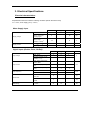
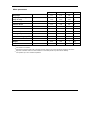
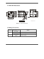
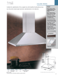
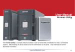
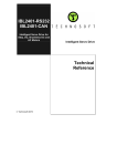
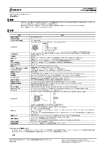
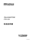
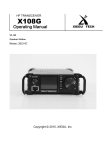
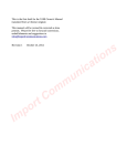
IS23x-DS
Version 1.1
Intelligent Stepper Motor
Intelligent Motor
User
Manual
Preliminary
© Technosoft 2007
TECHNOSOFT
IS23x-DS
v1.1
User Manual
P091.036.IS23x-DS.UM.0307
Technosoft S.A.
Buchaux 38
CH-2022 Bevaix, NE
Switzerland
Tel.: +41 (0) 32 732 5500
Fax: +41 (0) 32 732 5504
[email protected]
www.technosoftmotion.com/
Read This First
About This Manual
This book is the user manual for the IS23x-DS family of motors with integrated electronic. These
motors incorporate, in a single case, both the motor and a high performance digital drive. The
manual describes the IS23x-DS operation and explains how to set up IS23x-DS motors using the
EasySetUp commissioning software. The IS23x-DS family includes the following motors:
•
IS231-DS
•
IS232-DS
•
IS233-DS
Information about Cautions
This book may contain caution statements.
CAUTION ! This is an example of a caution statement.
A caution statement describes a situation that could potentially
cause harm to you, or to the IS23x-DS intelligent servo drive unit
© Technosoft 2007
III
IS23x-DS User Manual
If you Need Assistance …
If you want to …
Contact Technosoft at …
Visit Technosoft online
World Wide Web: http://www.technosoftmotion.com/
Receive general information
or assistance (see Note)
World Wide Web: http://www.technosoftmotion.com/
Email: [email protected]
Ask questions about
product operation or report
suspected problems
(see Note)
Fax: (41) 32 732 55 04
Email: [email protected]
Make suggestions about
or report errors in
documentation (see Note)
Mail: Technosoft SA
Buchaux 38
CH-2022 Bevaix, NE
Switzerland
Note: You need to register your IS23x system in order to get assistance and
support. Use the License Number of the EasySetUp software.
© Technosoft 2007
IV
IS23x-DS User Manual
Contents
1. Key Features
1
2. IS23x-DS Connection Diagrams
2
2.1.
Connectors and label
2
2.2.
Connector pins description
3
2.2.1.
J1 connector
3
2.2.2.
J3 connector
4
2.3.
Analog inputs connection
6
2.4.
Digital I/O connection
7
2.5.
Pulse & Direction inputs connection
8
2.6.
Supply connection
9
3. Electrical Specifications
10
4. IS23x-DS Dimensions
13
5. Mating Connectors
13
6. Motion modes and scaling factors
14
6.1.
Pulse & Direction motion mode
14
6.2.
Analog Reference motion mode
15
© Technosoft 2007
V
IS23x-DS User Manual
1. Key Features
• Fully digital servo drives and stepper motors embedded in the same case
• Cost efficient solution due to compactness and reduced wiring
• Ideal replacement / substitution of brushless axes, without hardware or software changes
of the indexing system
• Available in 3 motor lengths, offering from 55 to 189 Ncm of boosted holding torque **
(models IS231, IS232, IS233)
• Modes of operation:
• Position control with 5…24 V pulse & direction commands
• Speed control with ±10 V analogue input command
• Integrated Protections: short-circuit, over current, over temperature, over voltage and
under voltage
• Dedicated inputs/outputs:
• PULSE input (5…24 V)
• DIRECTION input (5…24 V)
• ENABLE input (5…24 V)
• READY output (5…24 V)
• Logic and Motor power supply: 12-48 VDC;
• Operating ambient temperature: 0-40°C
**
For operation up to 25°C ambient temperature
© Technosoft 2007
1
IS23x-DS User Manual
2. IS23x-DS Connection Diagrams
2.1.
Connectors and label
J3 Connector
J1 Connector
IS23
Digital Stepper Drive
Figure 2.1. IS23x – DS v1.1 drawing – backward view
© Technosoft 2007
2
IS23x-DS User Manual
2.2.
Connector pins description
CAUTION ! BEFORE THE CONNECTING / DISCONNECTING ANY OF THE
SIGNALS PLEASE TURN OFF ALL POWER SUPPLIES. ELSE SEVER
DAMAGE MAY OCCUR.
2.2.1. J1 connector
Table 2.1 J1 Connector pins description
Pin
Pin name
Type
Function / Alternate function / Comments
1
Pulse
I
It is used as PULSE digital input in Pulse & Direction motion mode
digital input; 5…24 V
2
Dir/Ref
I
•
Direction digital input, 5…24 V, in Pulse & Direction motion
mode
• Reference analogue input, –10…+10V, in Analog
Reference motion mode
3
Enable
I
It is used as Enable digital input. Connected to 5…24 V enable the
PWM outputs.
4
Ready
O
Ready digital output.
5
+VDC
I
Power supply
6
GND
-
Ground
The Dir line can be used as DIRECTION digital input in Pulse & Direction motion mode if pins 12 of the J3 connector are left open and as Reference analogue input if pins 1-2 of the same
connector are shorted.
© Technosoft 2007
3
IS23x-DS User Manual
2.2.2. J3 connector
Table 2.2 J3 Jumpers description
Pins
1-2
3-4
5-6
7-8
Pin
name
PD / AN
PP / SP
TRQ
STBY
9 - 10
RES3
11 - 12
RES2
13 - 14
RES1
15 - 16
RES0
© Technosoft 2007
State
Description
OPEN
(default)
Pulse & Direction motion mode
SHORT
Analog Reference motion mode
OPEN
(default)
Position Control – the motor is controlled in position
SHORT
Speed Control – the motor is controlled in speed
OPEN
(default)
Nominal Torque 2.5A
SHORT
Boosted Torque 2.8A The motor can be used at maximum ambient
temperature of 25 °C.
OPEN
(default)
Stand-by current is set to 100% IN
SHORT
Stand-by current is set to 25% IN
See Table
2.3.
Microstep Resolution. See Table 2.3.
4
IS23x-DS User Manual
The following table explains how to set the resolution (number of microsteps / step) using the
RES0, RES1, RES2 and RES3 jumpers.
Table 2.3 Jumpers combination for Resolution of microstep mode
Res
[μsteps/step]
RES3
RES2
RES1
RES0
256
OPEN
OPEN
OPEN
OPEN
128
OPEN
OPEN
OPEN
SHORT
64
OPEN
OPEN
SHORT
OPEN
32
OPEN
OPEN
SHORT
SHORT
16
OPEN
SHORT
OPEN
OPEN
8
OPEN
SHORT
OPEN
SHORT
4
OPEN
SHORT
SHORT
OPEN
2
OPEN
SHORT
SHORT
SHORT
1
SHORT
x
x
x
© Technosoft 2007
5
IS23x-DS User Manual
2.3. Analog inputs connection
IS23x - DS v1.1
Analog Inputs
Connection
J1
+3.3V
10K
10V
10K
REF
2
-10..+10V
30K
10V
15K
0.1uF
MotionChip
TM
GND
+3.3V
Figure 2.2. IS23x-DS v1.1 Analog inputs connection
© Technosoft 2007
6
IS23x-DS User Manual
2.4.
Digital I/O connection
Digital I/O connections
J1
PULSE
IS23x - DS v1.1
+3.3V
10K
PULSE
1
10K
+3.3V
ENABLE
3
10K
ENABLE
0.1uF
10K
+3.3V
DIR
10K
MotionChipTM
DIR/REF
0.1uF
10K
+3.3V
10K
GND
+
ANLG
30K
5.....24V
0.1uF
15K
+VMOT
LOAD
READY
10mA max
4
10R
0.125W
2.2K
10K
+3.3V
Figure 2.3. IS23x-DS v1.1 Digital input/output connection
© Technosoft 2007
7
IS23x-DS User Manual
2.5. Pulse & Direction inputs connection
Pulse & Direction Connection
Pulse
J1
PULSE
IS23x - DS v1.1
+3.3V
10K
PULSE
1
Direction
(0...5V or 0...24V)
MotionChipTM
10K
Pulse & Direction
Generator
+3.3V
DIR/REF
DIR
10K
10K
0.1uF
+3.3V
GND
10K
30K
15K
ANLG
0.1uF
+3.3V
Figure 2.4. IS23x-DS v1.1 Pulse & Direction inputs connection
© Technosoft 2007
8
IS23x-DS User Manual
2.6. Supply connection
Power supply
connection
IS23x - DS v1.1
+VMOT
+
5
VMOT
6
+3.3V
DC
12...48VDC
GND
MotionChipTM
J1
DC
GND
GND
4-phase Inverter
VMOT
Q7
Q5
Q3
Q1
A+
AB+
BQ8
Q6
Q4
Q2
Figure 2.5. IS23x-DS v1.1 Supply connection
© Technosoft 2007
9
IS23x-DS User Manual
3. Electrical Specifications
Electrical characteristics:
All parameters measured under the following conditions (unless otherwise noted):
Tamb = 25°C, motor supply (VMOT) = 24VDC ;
Motor Supply Input
Min.
Supply voltage
Max.
Units
Nominal values
12
48
VDC
Absolute maximum
values, continuous,
including ripple
0
50
VDC
-0.5
51
V
35
60
mA
±2.8
+6.5
A
Absolute maximum
values, surge
(duration ≤ 10mS)
Supply current
Typ.
†
Idle; VMOT = 24VDC
Operating
-6.5
Digital Inputs (Enable, Pulse, Dir/Ref)
Input voltage
Min.
Typ.
Max.
Logic “LOW”
- VMOT
0
1.6
Logic “HIGH”
4
5
VMOT
Absolute maximum, surge
(duration ≤ 1 S)
Input current
Input frequency
†
0
0
0
Logic “HIGH”; input voltage
= 5V
-
0.1
0.2
Logic “HIGH”; input voltage
= 24V
-
2
3
Pulse, Dir
0
250
Enable
0
0.25
Pulse, Dir
0 → 1 → 0 or 1 → 0 → 1
Enable
ESD Rating
© Technosoft 2007
Human body model (C=100pF,
R=1.5KΩ
10
V
+55
Logic “LOW”; Internal pulldown to GND
0 → 1 → 0 or 1 → 0 → 1
Pulse width
-50
Units
mA
KHz
2
μs
2
ms
±1
±2
KV
IS23x-DS User Manual
Digital Output (Ready)
Min.
Logic “LOW”; Output crt =
16mA
Output voltage
Output current
0.6
0.7
Logic HIGH leakage current
(open collector); output
voltage = 24 V
15μA
16
Output voltage
≤ (-0.5V) or ≥ (VMOT+0.5V);
Absolute maximum,
continuous
Units
VMOT + 0.5V
-0.5
†
Logic “LOW”
Clamp diodes current
Max.
V
Absolute maximum,
continuous
Typ.
50
100
-100
+100
500
mA
†
Output frequency
220 Ohm; External load to +5 V
0
Pulse width
220 Ohm; External load to +5 V
1
ESD Rating
Human body model (C=100pF,
R=1.5KΩ
±1
KHz
μs
±2
KV
Analog Inputs (REF)
Min.
Resolution
Typ.
Max.
10
Differential linearity
Guaranteed 10-bit
no-missing-codes
Units
bits
0.09
% FS
1
Offset error
±1
±3
% FS
1
Gain error
±2
±6
% FS
1
Bandwidth (-3dB)
250
Input voltage Operating range
Input voltage Absolute Maximum,
continuous
†
REF
Input impedance
REF
External potentiometer
Recommended
resistance
Hz
-10
+10
V
-50
+50
V
30
1
5
Min.
Typ.
KΩ
10
KΩ
Max.
Units
Others
Operating temperature
Weight
0
IS231-DS
0.65
IS232-DS
0.9
IS233-DS
1.3
Storage temperature
Not powered
Humidity
Non-condensing
© Technosoft 2007
40
11
°C
Kg
-40
85
°C
0
90
% RH
IS23x-DS User Manual
Motor parameters
IS231-DS
IS232-DS
IS233-DS
Step angle
1.8°
1.8°
1.8°
°
Step angle accuracy (full
step, no load)
± 5%
± 5%
± 5%
%
2
2.3
3.2
V
Current / Phase
2.8
2.8
2.8
A
Resistance / Phase
0.7
0.83
1.13
Ω
Inductance / Phase
1.4
2.2
3.6
mH
Detent Torque
18
35
72
mNm
0.45
0.85
1.60
Nm
0.5
1.0
1.8
Nm
Rotor Inertia
120
276
480
g-cm²
Weight
0.45
0.65
1
Kg
4
4
4
n°.
Rated Voltage
Holding Torque
Boosted Holding torque
**
Number of leads
Units
1
“FS” stands for “Full Scale”
† Stresses beyond those listed under “absolute maximum ratings” may cause permanent damage to the device.
Exposure to absolute-maximum-rated conditions for extended periods may affect device reliability.
** For operation up to 25°C ambient temperature
© Technosoft 2007
12
IS23x-DS User Manual
4. IS23x-DS Dimensions
K
56.4 1
L
K
47.14 0.20
K
4 x O 4.6
1.6
37.5
56.4 1
47.14 0.20
56.8
55.5
37.5
Digital Stepper Drive
K
IS23
0
O 6.35 -0.013
K
37.5
O 38.1 0.03
4.8
56
K
20.6 1
L
IS231
57.4
IS232 IS233
67.4 92.4
All dimensions in mm
Figure 3.1. IS23x-DS Dimensions
5. Mating Connectors
Connector
J1
J3
© Technosoft 2007
Manufacturer and
part number
Details
Molex 08-52-0123
Crimp-pins (6 pcs.)
Molex 22-01-3067
Connector housing - 6 pins
Fischer Elektronik
CAB10
Jumpers 2 mm pitch
13
IS23x-DS User Manual
6. Motion modes and scaling factors
6.1.
Pulse & Direction motion mode
The Pulse & Direction mode allows you to set the drives working with an external Pulse &
Direction command provided by another device. The Pulse & Direction command consists of 2
digital signals that must be connected to specially inputs of the drive:
•
•
Pulse – a sequence of pulses. Each pulse represents a position unit. The sum of the
pulses indicates the position displacement to be performed. The variation in number of
pulses during one sampling period represents a speed reference.
Direction - a digital signal which indicates the reference sign (motion direction)
Depending on the reference type, 2 pulse & direction modes are possible:
•
Position pulse & direction - the motor is controlled in position.
•
Speed pulse & direction - the motor is controlled in speed.
These modes are selected by PP / SP jumper.
The scaling factor for the motor position is:
Motor position [rot] =
1
× No_pls [pulses]
N S [ st / rot ] × Res[ μst / st ]
where NS = 200 [steps/rot]
- number of steps
Res = 1 … 256 [μst/st] - resolution, the number of microsteps / step; It depends by
jumpers positions (RES0, RES1, RES2 and RES3).
No_pls [pulses]
- the number of pulses applied to Pulse pin
The scaling factor for the motor speed is:
Motor speed [rot/s] =
1
× No_pls_sec [pulses/s]
N S [ st / rot ] × Res[ μst / st ]
where NS = 200 [steps/rot]
- number of steps
Res = 1 … 256 [μst/st] - resolution, the number of microsteps / step; It depends by
jumpers positions (RES0, RES1, RES2 and RES3).
No_pls_sec [pulses/s]
- the number of pulses per second applied to Pulse pin
© Technosoft 2007
14
IS23x-DS User Manual
6.2.
Analog Reference motion mode
In Analog Reference mode, an external device provides the target reference as an analog
voltage connected to the Dir/Ref input;
The scaling factor for the motor speed is:
Motor speed [rot/s] =
K SPD [μst / s / V ]
× REF [V]
N S [ st / rot ] × Res[ μst / st ]
where KSPD = 32324.3 [μst / s / V]
NS = 200 [steps/rot]
Res = 1 … 256 [μst/st]
REF[V]
- speed scale factor
- number of steps
- resolution, the number of microsteps / step; It depends
by jumpers positions (RES0, RES1, RES2 and RES3).
- external reference voltage applied to Dir/Ref pin
The scaling factor for the motor position is:
Motor position [rot] =
K POS [μst / s / V ]
× REF [V]
N S [ st / rot ] × Res[ μst / st ]
where KPOS = 1656.57 [μst / V]
NS = 200 [steps/rot]
Res = 1 … 256 [μst/st]
REF[V]
© Technosoft 2007
- position scale factor
- number of steps
- resolution, the number of microsteps / step;
It depends by jumpers positions (RES0, RES1, RES2
and RES3).
- external reference voltage applied to Dir/Ref pin
15
IS23x-DS User Manual
This page is empty
© Technosoft 2007
16
IS23x-DS User Manual