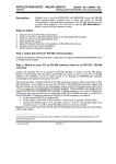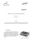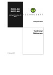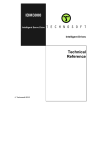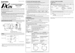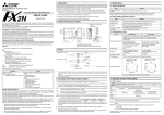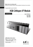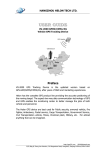
1
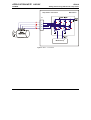
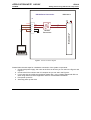
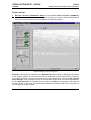
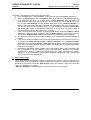
APPLICATION NOTE 045.001 12/20/02 IPS110 Getting started using IPS110 with a step motor Problem: For new users of an intelligent drive, starting to implement a motion control application can be a quite complex task. You need to know how to hook-up the components of the motion system, to configure them (motor, sensors and drive), test their functionality, identify parameters and tune controllers. Finally, execute a simple movement to validate the basic system functionality and focus on your real motion application. Solution: ♦ Drive : ♦ S/W environment : Description: This Application Note explains: - how to perform the basic hardware connections for IPS110 and step motor without encoder sensor; - how to create under the ‘IPM Motion Studio’ a new project/application for motion control with a step motor; - how to configure the components of the motion system: motor, sensors, drive; - how to test the functionality of the system components; - how to identify the motor parameters and tune the controllers; - how to run and use data analysis tools; - how to save your project/application; Technosoft 2002 Technosoft Intelligent Servo Drive IPS110 Technosoft IPM MotionStudio – V2.0.1.3 or above APN.001 - 1 APPLICATION NOTE 045.001 IPS110 12/20/02 Getting started using IPS110 with a step motor Connections: Power supply connection IPS110 v1.0 +VLOG VLOG +3.3V +5V DC + 5V GND GND DC + VMOT +VMOT To motor Figure 1. Power Supply – J1 Connector Technosoft 2002 APN.001 - 2 DSP Controller J1 APPLICATION NOTE 045.001 IPS110 12/20/02 Getting started using IPS110 with a step motor IPS110V1.0 Step motor connection J3 1 coil per phase TM MotionChip Figure 2. Motor – J3 connector Technosoft 2002 APN.001 - 3 APPLICATION NOTE 045.001 12/20/02 IPS110 Getting started using IPS110 with a step motor RS-232 Serial Connection IPS110v1.0 J1 +5V Tx232 8 RS-232 Transceiver MotionChipTM 3 10 Rx232 11 GND 7 Figure 3. RS-232 connection diagram Please follow the next steps for a hardware connection of the system components: 1. Connect the power supply, the motor to the IPS110 drive as you can see in the Figure1 and Figure 2. 2. Connect the IPS110 drive to the PC computer as you can see in the Figure 3. 3. If you have also an IOIPS110 board then please refer to the “Getting started with IPS110 drive using IOIPS110 board” application note for more detailed information. 4. First power up the PC 5. Secondly power up the drive Technosoft 2002 APN.001 - 4 APPLICATION NOTE 045.001 12/20/02 IPS110 Getting started using IPS110 with a step motor Project set-up: 1. Start the execution of IPM Motion Studio; use the Windows “Start | Programs | IPM Motion Studio | IPM Motion Studio” menu command. A dialog as in Figure 6 should be displayed if the communication with the board is established and operates properly. Figure 6. IPM Motion Studio opening screen Remarks: If the board is not detected, the “Board NOT found” message is displayed in the bottom of the program window. In this case check first the serial cable and the power supply connections on the IPS110 and PC, exit the program and launch it again. Alternatively, use the “Tools | Refresh Serial Settings” menu command, to retry to communicate with the drive. If the board was detected, the text “Board present” or the board type and version (as “IPS110”) is displayed in the bottom of program window. In this case, the communication between the IPM drive and the PC works fine, so you can start to use the program. Technosoft 2002 APN.001 - 5 APPLICATION NOTE 045.001 12/20/02 IPS110 Getting started using IPS110 with a step motor Otherwise, if the problem persists, follow the next steps: a. From the Tools menu, choose Options. This command opens the Options dialog box. b. Select the Serial port tab from the Options dialog box. Select the “Serial type” (RS-232 for a single axis structure). Try to start using a smaller Baud rate value (as 9600). For single axis structures (only one IPS exists in the system and is connected directly to the PC), set the “Host Address” as 255 (default). Select the correct “COM Port Number” of the PC, where the serial cable was connected. Press the OK button. If the communication with the IPS drive does not operate properly, an error message is displayed “Cannot open the serial port”. Check if the selected COM port is correct, and not used by another resource of the PC (as mouse, modem, etc). Try again. c. If the communication works properly, pressing the OK button will exit the Options | Serial port dialog, without an error message, and the “Board present” or the board type and version (e.g. “P045.001.E001.F005C”) is displayed in the bottom of program window. d. You can in this case try to increase the baud rate, up to the maximal 115 kbaud allowed by the PC. e. If the communication operates usually but gives communication errors from time to time, try to increase the “Read interval timeout”, “Timeout multiplier” and “Timeout constant” parameters, from the same Options | Serial port settings dialog. Note that this is related to some PCs hardware operation, and that usually the default values for these parameters need not to be modified. f. Note that the IPM Motion Studio program can be used offline, with no IPS connected to the PC, or powered-up. All the modeling, project and applications definition, and program wizards can be used to configure and parameterize the system and define the motion. Obviously, no IPS information, motion system parameter identification and measurement data can be performed or displayed 2. Start a new project All the applications in IPM Motion Studio are organized as projects. A project is specific for a selected type of IPM drive (IPM100, IPM240 or IPS110) and a specific motor type (DC brushed, brushless or step motor). Press the “New Project” button, and select the type of the drive and motor you installed in your system: “IPS110 > Step Motor – Closed Loop”, in order to create such a new project. Technosoft 2002 APN.001 - 6 APPLICATION NOTE 045.001 12/20/02 IPS110 Getting started using IPS110 with a step motor Figure 7. Create a new project in IPM Motion Studio 3. Project diagram structure A schematic diagram of the motion system will be displayed on the screen. It contains the three basic elements of the system, i.e. the motor and sensors, the drive and, as a separate component, the motion reference generator module. Each of these elements can be selected and will allow you to define the parameters and specific settings associated to that element. Note that the new project is opened with some elements already pre-loaded. You need to change / test / validate these elements, in order to fit to your configuration, as described in the next steps. A small arrow pointing to the left upper corner of the element shows you which element to define/check next. Technosoft 2002 APN.001 - 7 APPLICATION NOTE 045.001 12/20/02 IPS110 Getting started using IPS110 with a step motor Figure 8. Motion system diagram in IPM Motion Studio 4. Choose and test the motor and load Click on the Motor icon. The motor and load dialog will be opened, as in Figure 9. The dialog allows you to choose and / or parameterize your motor and sensors. You can select the motor from a predefined database (“Default Step motors” or “User”). You can also, starting from a given motor, change its parameters, in order to fit your motor characteristics. Several specific tests can be performed, allowing you to check the correctness of some motor parameters, the correct operation of existing sensors as encoder and connection of motor to the drive. WARNING! Note that most of these tests apply power to the motor. Please check carefully the motor parameters, mainly the nominal and maximum current values. Each test applying a voltage to the motor will be performed with a protection limit on the current. If this limit exceeds the motor maximum current, severe damage of the motor can occur! Technosoft 2002 APN.001 - 8 APPLICATION NOTE 045.001 12/20/02 IPS110 Getting started using IPS110 with a step motor In order to perform the tests in the proper order, use the “Guideline Assistant” textbox, and follow the steps as described there Step 1. Select your motor from the corresponding database. If your motor does not exist in the database, proceed through all next steps in order to define your motor and sensors data. In either case, use these steps to verify the new functionality. Figure 9. The Motor Dialogue Step 2. Check the values for nominal and peak currents (given by the motor catalogue data). Modify these values if needed. Step 3. Check the maximum motor speed value, as a motor catalog data. Modify this value if needed. Step 4. Check the number of motor steps. Modify this value according to motor catalog. Technosoft 2002 APN.001 - 9 APPLICATION NOTE 045.001 12/20/02 IPS110 Getting started using IPS110 with a step motor Step 5. Check the torque constant value, as a motor catalog data. Modify this value if needed. Step 6. Check the phase resistance and inductance values (these are the motor catalogue data). Modify these values if needed. Step 7. Check-in the “Encoder” checkbox if a quadrature incremental encoder is mounted on your motor shaft. If your motor doesn’t have mounted any encoder on its shaft leave the checkbox unchecked. Step 8. Check in the “Temperature” checkbox if you have connected an output of the motor temperature sensor to the corresponding connector pin of the IPS. Check the values of the temperature sensor parameters. Step 9. Check the value of the Motor and Load - Total Inertia. Press the “Identify Total Inertia” button to auto-detect this parameter. The “Total Inertia Identification Test” dialog will open. Check the value of the test current and that of the current protection to be used during the test and follow the “Test Procedure” steps. The test will rotate the motor and estimate the total inertia (motor + load), as reported at motor shaft. Please note that this test will try to impose a constant torque in the motor. In case that you have a new motor that was not chosen from the motor database, you need to perform the tuning of the current controller before running this test. The current controller tuning can be validated in the Drive dialogue. Technosoft 2002 APN.001 - 10 APPLICATION NOTE 045.001 12/20/02 IPS110 Getting started using IPS110 with a step motor Figure 10. Total Inertia Identification Test Step 10. Exit the Motor and Load dialog, by pressing the OK button. 5. Define the control scheme, tune and test controllers Click on the Drive icon. The drive dialog will be opened, as in Figure 11. The dialog allows you to choose and parameterize the control scheme to be implemented in your application. You can select which control loops to be activated in the scheme, tune and test the activated controllers, and also select and setup the protections of the drive. Several specific tests can be performed, allowing you to check the behavior of the control loops. WARNING! Note that most of these tests apply power to the motor. Please check carefully the motor parameters, mainly the nominal and maximum current values. Each test applying a voltage to the motor will be performed with a protection limit on the current. If this limit exceeds the motor maximum current, severe damage of the motor can occur! In order to perform the tests in the proper order, use the “Guideline Assistant” textbox, and follow the steps as described there Technosoft 2002 APN.001 - 11 APPLICATION NOTE 045.001 12/20/02 IPS110 Getting started using IPS110 with a step motor Figure 11. The Drive dialog Step 1. Select your controller scheme configuration. Check/uncheck the position controller and the Control Mode (Open Loop or Closed Loop) to be used. Note that the Closed Loop mode requires an encoder. Thus, if encoder sensor was not defined in the motor dialog, the Closed Loop mode is not selectable. Step 2. In the “Motion reference” group-box, select the motion reference type to be used when the motion will be executed. Use the “Internal Reference Generator” selection for motions generated through TML motion commands. In this case, the reference will be defined at a latter stage, in the “Motion” block of the motion system diagram. Step 3. In the “Drive Operation Parameters” group-box set the value of the DC voltage power supply (Vdc). Use the “Detect” button to measure its actual value as applied to the drive. The Technosoft 2002 APN.001 - 12 APPLICATION NOTE 045.001 12/20/02 IPS110 Getting started using IPS110 with a step motor “VDC Detection Test” dialog will open. The test will measure the actual value of the power supply voltage applied to the IPS drive. Figure 12. VDC Detection Test Step 4. In the “Current Controller” group-box you can set the current controller parameters Kp (proportional) and Ki (integral). Use the “Tune” button to compute these parameters based on the imposed dynamical performances of the closed loop, and on the system parameters. The “Current Controller Tuning” dialog will open in this case. If you set the dump factor and the passband of the closed control loop, the program will automatically compute the controller coefficients, based also on motion system parameter values. Expected system response to a step reference input in the controller is graphically displayed, as well as the frequency characteristic of the closed loop structure. Once you exit this dialog by pressing the OK button, the newly computed controller parameters replace the previous values. If you are not comfortable with the damp factor and passband parameters, you may cancel the Current Controller – Tuning dialogue and type directly the Kp, Ki coefficient values in the Current Controller group-box: Figure 13. Current Controller group-box Technosoft 2002 APN.001 - 13 APPLICATION NOTE 045.001 12/20/02 IPS110 Getting started using IPS110 with a step motor Figure 14. Current Controller Tuning Use the “Test” button in order to test the step response of the closed current loop, for the actual values of the controller parameters. The “Current Controller Tuning Test” dialog will open. Check the value of the current reference to be used during the test, as well as the protection current value (see the time diagram included in the dialog in order to have an explanation of these parameters), and follow the “Test Procedure” steps. The test will apply a current reference to the motion system, and display the current loop response to that reference. The current controller is implemented using the defined control parameter values (Kp and Ki). You may repeat the above operations described in Step 4 until you are satisfied with the current loop response. Technosoft 2002 APN.001 - 14 APPLICATION NOTE 045.001 12/20/02 IPS110 Getting started using IPS110 with a step motor Figure 15. Current Controller Tuning Test Step 5. For the “Start mode” group-box set up de corresponding parameters. Step 6. Set the Transition speed level for Transition speed from step-less to full step. Step 7. Press the OK button of the Drive dialog, in order to validate the defined control structure and its associated parameters. 6. Define and test the motion Click on the Motion icon. The motion wizard dialog will be opened, as in Figure 16. Technosoft 2002 APN.001 - 15 APPLICATION NOTE 045.001 12/20/02 IPS110 Getting started using IPS110 with a step motor Figure 16. The Motion Wizard dialog The dialog allows you to insert specific motion sequences and other TML commands, as arithmetic, I/O operations, events, etc. Details about the functionality and features of the Motion Wizard are given in Chapter 5 of “IPM Motion Studio User Manual”. In order to perform a simple motion, only to validate the complete overview of this paragraph, use the predefined motion sequence already defined in the motion profile by clicking the button In the associated Motion Profiles dialog window you can define a position profile as you can see in the figure below: Technosoft 2002 APN.001 - 16 APPLICATION NOTE 045.001 12/20/02 IPS110 Getting started using IPS110 with a step motor Figure 17. The Motion Profiles dialog You can define the profile parameters, i.e. the acceleration/deceleration, the slew speed, and the reference position value. Once the motion is defined, exit the Motion Wizard by pressing the OK button. You can now generate the complete TML code associated to the chosen configuration, download it to the IPM drive, and execute it. You simply press the “Run” button, and all the operations associated to this command will be executed: reset the IPM, generate the TML code based on the configuration and imposed parameters, as well as on the motion, download the code to the IPM, and start its execution. The motor should execute the imposed motion. You can upload the data logged during the motion by selecting the data logger window, click the right button of the mouse, and activate the “Upload Data” menu command. The variables stored during the execution of the motion will be displayed on the screen. You can Stop the motor by disabling the PWM outputs (Stop the motion by Axisoff) Reset the drive Technosoft 2002 APN.001 - 17 APPLICATION NOTE 045.001 12/20/02 IPS110 Getting started using IPS110 with a step motor Figure 18. The Data Logger dialog More details about the data analysis tools (Logger and Control Panel) are presented in the IPM Motion Studio User Manual. 7. Save and close the project The precedent paragraphs guided you through the process of starting a motion project, configuring and parameterizing it, defining the motion and finally executing it on the IPS drive. As one can see from the described procedure, the steps to follow are straightforward, and allow you to validate the operation of your complete drive configuration. When arrived at this point, you can start and really go into details related to all the features of the program, mainly focusing on the motion description and implementation. The just defined project, completed with the correct structure definition and parameters of the elements (motor, sensors, controllers, etc.), can be saved for further use. Select the “Project | Technosoft 2002 APN.001 - 18 APPLICATION NOTE 045.001 IPS110 12/20/02 Getting started using IPS110 with a step motor Close” menu command. You’ll be asked to give a name for the project and the application to be saved. Latter on, you’ll be able to open the project, in the same status as when saved the last time. 11.5 mm (0.453”) Drive layout: 22.86 mm (0.9”) 3 mm (0.118”) ID0 ID1 ID2 ID3 ID4 ID5 +VMOT +VMOT A+ AB+ BGND GND +5V Tx232 Rx232 Reset ENCA ENCB Puls+ PulsDir+ DirIO#35 / Sin / LSP / CAPI IO#36 / Cos / LSN / CAPI2 Reference Feedback CAN_HI CAN_LO A+ ABB+ 8.2 mm (0.323”) 2.54 mm (0.1”) 50.0 mm (1.969”) 0.46 mm (0.018”) 26.5 mm (1.043”) Figure 19. IPS110v1.0 drive layout NOTE : If you have also an IOIPS110 board you should refer to the “Getting started with IPS110 using IOIPS110 board” application note, for more detailed information. This document deals solely on the IPS110 drive itself. Technosoft 2002 APN.001 - 19 APPLICATION NOTE 045.001 12/20/02 IPS110 Getting started using IPS110 with a step motor This page is empty Technosoft 2002 APN.001 - 20