1
Cat. No. H08E-EN-01
Cat. No. H08E-EN-01
Digital Temperature Controllers E5CN/E5AN/E5EN/E5GN
Getting Started Manual
Authorized Distributor:
Cat. No. H08E-EN-01
Note: Specifications subject to change without notice.
Printed in Europe
E5CN
E5AN
E5EN
E5GN
ZX-T Series
Digital
Temperature Controllers
Getting Started Manual
E5CN/E5AN/E5EN/E5GN
Digital Temperature Controllers
Getting Started Manual
Basic Type
Revised August 2010
This manual needs the H04E+E5CN(-U) and H03E+E5EN/AN datasheet for
selection and installation. (This manual is a selection from the full manual H156)
iv
Preface
The E5CN, E5CN-U, E5AN, E5EN, and E5GN are Digital Temperature Controllers. The E5CN and
E5CN-U are both compact temperature controllers, with the E5CN featuring screw terminal connections, and the E5CN-U featuring socket pin connections. The E5GN can be connected using screw terminals or screwless clamp terminals. The main functions and characteristics of these Digital
Temperature Controllers are as follows:
• Any of the following types of input can be used: thermocouple, platinum
resistance thermometer, infrared sensor, analog voltage, or analog current.
• Either standard or heating/cooling control can be performed.
• Both auto-tuning and self-tuning are supported.
• Event inputs can be used to switch set points (multi-SP function), switch
between RUN and STOP status, switch between automatic and manual
operation, start/reset the simple program function, and perform other
operations. (Event inputs are not applicable to the E5CN-U.)
• Heater burnout detection, heater short (HS) alarms, and heater overcurrent (OC) functions are supported. (Applicable to E5CN, E5AN, E5EN,
and E5GN models with heater burnout detection function.)
• Communications are supported. (Applicable to E5CN, E5AN, E5EN, and
E5GN models with communications.)
• User calibration of the sensor input is supported.
• The structure is waterproof (IP66). (Not applicable to the E5CN-U.)
• Conforms to UL, CSA, and IEC safety standards and EMC Directive.
• The PV display color can be switched to make process status easy to
understand at a glance.
This manual describes the E5CN, E5CN-U, E5AN, E5EN, and E5GN for basic functions. Read this
manual thoroughly and be sure you understand it before attempting to use the Digital Temperature
Controller and use the Digital Temperature Controller correctly according to the information provided.
Keep this manual in a safe place for easy reference. Refer to the full manual for advanced settings:
E5CN/E5AN/E5EN/E5GN Digital Temperature Controllers User’s Manual (Cat. No. H156).
Refer to the following manual for further information on communications: E5CN/E5AN/E5EN/E5GN
Digital Temperature Controllers Communications Manual Basic Type (Cat. No. H158).
Refer to the following manual for information on the Advanced Type Controllers: E5CN/E5AN/E5EN-H
Digital Temperature Controllers User's Manual Advanced Type (Cat. No. H157).
Visual Aids
The following headings appear in the left column of the manual to help you locate different types of
information.
Note Indicates information of particular interest for efficient and convenient operation of the product.
1,2,3...
1. Indicates lists of one sort or another, such as procedures, checklists, etc.
v
© OMRON, 2010
All rights reserved. No part of this publication may be reproduced, stored in a retrieval system, or transmitted, in any form, or
by any means, mechanical, electronic, photocopying, recording, or otherwise, without the prior written permission of
OMRON.
No patent liability is assumed with respect to the use of the information contained herein. Moreover, because OMRON is constantly striving to improve its high-quality products, the information contained in this manual is subject to change without
notice. Every precaution has been taken in the preparation of this manual. Nevertheless, OMRON assumes no responsibility
for errors or omissions. Neither is any liability assumed for damages resulting from the use of the information contained in
this publication.
vi
Precautions for Operation
1)
2)
3)
4)
It takes approximately two seconds for the outputs to turn ON from after the power supply is turned ON.
Due consideration must be given to this time when incorporating Temperature Controllers into a control
panel or similar device.
Make sure that the Temperature Controller has 30 minutes or more to warm up after turning ON the power
before starting actual control operations to ensure the correct temperature display.
When executing self-tuning, turn ON power for the load (e.g., heater) at the same time as or before
supplying power to the Temperature Controller. If power is turned ON for the Temperature Controller
before turning ON power for the load, self-tuning will not be performed properly and optimum control will
not be achieved. When starting operation after the Temperature Controller has warmed up, turn OFF the
power and then turn it ON again at the same time as turning ON power for the load. (Instead of turning the
Temperature Controller OFF and ON again, switching from STOP mode to RUN mode can also be used.)
Avoid using the Controller in places near a radio, television set, or wireless installing. The Controller may
cause radio disturbance for these devices.
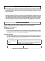
Shipping Standards
The E5CN, E5CN-H, E5AN, E5AN-H, E5EN, and E5EN-H comply with Lloyd's standards. When applying the
standards, the following installation and wiring requirements must be met in the application.
■ Application Conditions
1) Installation Location
The E5CN, E5CN-H, E5AN, E5AN-H, E5EN, and E5EN-H comply with installation category ENV1 and
ENV2 of Lloyd's standards. Therefore, they must be installed in a location equipped with air conditioning. They must therefore be installed in a location equipped with air conditioning. They cannot be used
on the bridge or decks, or in a location subject to strong vibration.
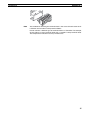
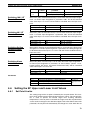
2) Wiring Conditions
Install the recommended ferrite core and wrap the line around it three turns for the applicable lines
(e.g., power supply cable line and signal lines) of the models listed in the following table. (See illustrations.) Install the ferrite cores as close to the terminal block of the E5@N as possible. (As a guideline,
the ferrite core should be within 10 cm of the terminal block.)
● Lines Requiring Ferrite Cores
Model
E5CN, E5CN-U, or E5CN-H
E5EN, E5AN, E5EN-H, or
E5AN-H
Signal and power lines provided with ferrite cores
Input power supply
Input power supply and I/O lines (control outputs (1 and 2), communications,
event inputs (1 to 4), transfer output, and external power supply (Advanced
Type models do not have an external power supply.)
● Recommended Ferrite Core
Manufacturer
Model
Seiwa Electric Mfg. Co., Ltd.
E04RA310190100
Note This part is available from Omron stock.
vii
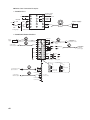
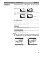
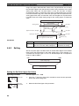
● Ferrite Core Connection Examples
1. E5CN/E5CN-H
Auxiliary outputs
(relay outputs)
+
1
11
6
2
12
7
3
13
8
4
14
9
5
15
10
Auxiliary output 2
Control output 1
+
DO NOT
USE
mA
−
−
V
DO NOT
USE
−
DO NOT A
USE
−
●
B
Auxiliary
output 1
●
Power supply
Input power
supply
●
+
Analog input
B
+
AC/DC
3 turns
TC/Pt universal input
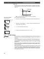
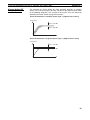
2. E5AN/E5EN/E5AN-H/E5EN-H
Power
supply
AC/DC
Event Inputs
3 turns
Input power
supply
+
Connected to
control output 1.
1
21
11
2
22
12
3
23
13
4
24
14
5
25
15
6
26
16
EV1
Control
CT1/CT2 Output 2
+
Control
CT1
Output 2
−
CT2
DO NOT
USE
7
27
17
DO NOT
USE
8
28
18
Control output 1
3 turns
−
Auxiliary output 3
Auxiliary output 2
9
29
19
EV2
A
DO NOT
USE
−
10
30
20
3 turns
External Power
Supply
+
External power supply
12 VDC, 20 mA
−
DO NOT
USE
V
B
+
+
TC/Pt universal input
3 turns
+
DO NOT
USE
−
B
Auxiliary output 1
Connected to
communications or
event inputs 1 and 2.
mA
−
DO NOT
USE
Analog input
Communications
21
RS-232C
Connected to event
inputs 3 and 4.
EV3
3 turns
SD
11
B (+)
12
RD
12
A (−)
13
SG
13
DO NOT USE
24
21
DO NOT USE
21
B (+)
25
22
DO NOT USE
22
A (−)
+
Connected to
transfer output.
3 turns
26
27
Transfer output
−
DO NOT USE
DO NOT USE
viii
23
EV4
DO NOT USE
RS-485
11
22
28
29
30
4 to 20 mA DC
(Load: 600 Ω max.)
Connected to
control output 2
or external
power supply.
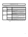
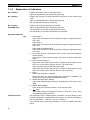
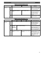
Preparations for Use
Be sure to thoroughly read and understand the manual provided with the product, and check the following points.
Timing
Check point
Purchasing the prod- Product appearance
uct
Setting the Unit
Wiring
Operating environment
Details
After purchase, check that the product and packaging are not dented or
otherwise damaged. Damaged internal parts may prevent optimum
control.
Product model and speci- Make sure that the purchased product meets the required specificafications
tions.
Product installation loca- Provide sufficient space around the product for heat dissipation. Do not
tion
block the vents on the product.
Terminal wiring
Do not subject the terminal screws to excessive stress (force) when
tightening them.
Make sure that there are no loose screws after tightening terminal
screws to the specified torque of 0.74 to 0.90 N·m (see note).
Be sure to confirm the polarity for each terminal before wiring the terminal block and connectors.
Power supply inputs
Wire the power supply inputs correctly. Incorrect wiring will result in
damage to the internal circuits.
Ambient temperature
The ambient operating temperature for the product is −10 to 55°C (with
no condensation or icing). To extend the service life of the product,
install it in a location with an ambient temperature as low as possible. In
locations exposed to high temperatures, if necessary, cool the products
using a fan or other cooling method.
Vibration and shock
Check whether the standards related to shock and vibration are satisfied at the installation environment. (Install the product in locations
where the conductors will not be subject to vibration or shock.)
Foreign particles
Install the product in a location that is not subject to liquid or foreign
particles entering the product.
Note The tightening torque is 0.5 N·m for the E5CN-U and 0.43 to 0.58 N·m for the
E5GN. The terminal torque is 0.5 to 0.6 N·m for auxiliary output 2 on the
E5GN.
ix
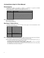
Conventions Used in This Manual
Model Notation
The E5CN-@@@, E5CN-@@@U, E5AN-@@@, E5EN-@@@, and E5GN-@@@ are given as the E5CN,
E5CN-U, E5AN, E5EN, and E5GN when they share functionality.
The following notation is used when specifying differences in functionality.
Notation
E5@N-@@@B
E5@N-@@@03
E5@N-@@H
E5@N-@@HH
E5@N-@Q
E5@N-@@P
E5@N-@@@01
E5@N-@@F
Options
Two event inputs
RS-485 communications
One of HB, HS, and heater overcurrent detection
Two of HB, HS, and heater overcurrent detection (See note 1.)
Control output 2 (voltage output) (See note 1.)
External power supply to ES1B (See note 1.)
RS-232C communications (See note 2.)
Transfer output (See note 3.)
Note: (1) Excluding the E5GN.
(2) Excluding the E5CN.
(3) The E5AN and E5EN only.
Meanings of Abbreviations
The following abbreviations are used in parameter names, figures and in text explanations. These
abbreviations mean the following:
Symbol
PV
SP
SV
AT
ST
HB
HS
OC
LBA
EU
Term
Process value
Set point
Set value
Auto-tuning
Self-tuning
Heater burnout
Heater short (See note 1.)
Heater overcurrent
Loop burnout alarm
Engineering unit (See note 2.)
Note: (1) A heater short indicates that the heater remains ON even when the control output from the Temperature Controller is OFF because the SSR has failed or for any other reason.
(2) “EU” stands for Engineering Unit. EU is used as the minimum unit for engineering units such as °C,
m, and g. The size of EU varies according to the input type.
For example, when the input temperature setting range is –200 to +1300°C, 1 EU is 1°C, and when
the input temperature setting range is –20.0 to +500.0°C, 1 EU is 0.1°C.
For analog inputs, the size of EU varies according to the decimal point position of the scaling setting,
and 1 EU becomes the minimum scaling unit.
x
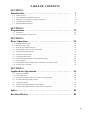
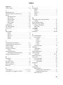
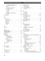
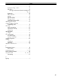
TABLE OF CONTENTS
SECTION 1
Introduction. . . . . . . . . . . . . . . . . . . . . . . . . . . . . . . . . . . . . . .
1
1-1
Names of Parts. . . . . . . . . . . . . . . . . . . . . . . . . . . . . . . . . . . . . . . . . . . . . . . . . . . . . . . . . . . .
2
1-2
I/O Configuration and Main Functions . . . . . . . . . . . . . . . . . . . . . . . . . . . . . . . . . . . . . . . . .
6
1-3
Setting Level Configuration and Key Operations . . . . . . . . . . . . . . . . . . . . . . . . . . . . . . . . .
12
1-4
Communications Function. . . . . . . . . . . . . . . . . . . . . . . . . . . . . . . . . . . . . . . . . . . . . . . . . . .
15
1-5
Insulation Block Diagrams . . . . . . . . . . . . . . . . . . . . . . . . . . . . . . . . . . . . . . . . . . . . . . . . . .
17
SECTION 2
Preparations . . . . . . . . . . . . . . . . . . . . . . . . . . . . . . . . . . . . . .
19
2-1
Installation . . . . . . . . . . . . . . . . . . . . . . . . . . . . . . . . . . . . . . . . . . . . . . . . . . . . . . . . . . . . . . .
20
2-2
Using the Support Software Port . . . . . . . . . . . . . . . . . . . . . . . . . . . . . . . . . . . . . . . . . . . . . .
26
SECTION 3
Basic Operation. . . . . . . . . . . . . . . . . . . . . . . . . . . . . . . . . . . .
29
3-1
Initial Setting Examples. . . . . . . . . . . . . . . . . . . . . . . . . . . . . . . . . . . . . . . . . . . . . . . . . . . . .
30
3-2
Setting the Input Type . . . . . . . . . . . . . . . . . . . . . . . . . . . . . . . . . . . . . . . . . . . . . . . . . . . . . .
32
3-3
Selecting the Temperature Unit . . . . . . . . . . . . . . . . . . . . . . . . . . . . . . . . . . . . . . . . . . . . . . .
34
3-4
Selecting PID Control or ON/OFF Control . . . . . . . . . . . . . . . . . . . . . . . . . . . . . . . . . . . . . .
34
3-5
Setting Output Specifications . . . . . . . . . . . . . . . . . . . . . . . . . . . . . . . . . . . . . . . . . . . . . . . .
34
3-6
Setting the Set Point (SP) . . . . . . . . . . . . . . . . . . . . . . . . . . . . . . . . . . . . . . . . . . . . . . . . . . .
39
3-7
Using ON/OFF Control . . . . . . . . . . . . . . . . . . . . . . . . . . . . . . . . . . . . . . . . . . . . . . . . . . . . .
40
3-8
Determining PID Constants (AT, ST, Manual Setup) . . . . . . . . . . . . . . . . . . . . . . . . . . . . . .
42
3-9
Alarm Outputs . . . . . . . . . . . . . . . . . . . . . . . . . . . . . . . . . . . . . . . . . . . . . . . . . . . . . . . . . . . .
49
3-10 Using Heater Burnout, Heater Short, and Heater Overcurrent Alarms . . . . . . . . . . . . . . . . .
53
3-11 Setting the No. 3 Display. . . . . . . . . . . . . . . . . . . . . . . . . . . . . . . . . . . . . . . . . . . . . . . . . . . .
61
SECTION 4
Applications Operations. . . . . . . . . . . . . . . . . . . . . . . . . . . . .
63
4-1
Shifting Input Values . . . . . . . . . . . . . . . . . . . . . . . . . . . . . . . . . . . . . . . . . . . . . . . . . . . . . . .
64
4-2
Alarm Hysteresis . . . . . . . . . . . . . . . . . . . . . . . . . . . . . . . . . . . . . . . . . . . . . . . . . . . . . . . . . .
68
4-3
Setting Scaling Upper and Lower Limits for Analog Inputs. . . . . . . . . . . . . . . . . . . . . . . . .
69
4-4
Executing Heating/Cooling Control . . . . . . . . . . . . . . . . . . . . . . . . . . . . . . . . . . . . . . . . . . .
70
4-5
Using Event Inputs . . . . . . . . . . . . . . . . . . . . . . . . . . . . . . . . . . . . . . . . . . . . . . . . . . . . . . . .
74
4-6
Setting the SP Upper and Lower Limit Values . . . . . . . . . . . . . . . . . . . . . . . . . . . . . . . . . . .
79
4-7
Using the SP Ramp Function to Limit the SP Change Rate . . . . . . . . . . . . . . . . . . . . . . . . .
81
Index. . . . . . . . . . . . . . . . . . . . . . . . . . . . . . . . . . . . . . . . . . . . .
85
Revision History . . . . . . . . . . . . . . . . . . . . . . . . . . . . . . . . . . .
88
xi
About this Manual:
This manual describes the E5CN/CN-U/AN/EN Digital Temperature Controllers and includes the sections described below.
Please read this manual carefully and be sure you understand the information provided before
attempting to set up or operate an E5CN/CN-U/AN/EN Digital Temperature Controller.
• Overview
Section 1 introduces the features, components, and main specifications of the E5CN/CN-U/AN/EN/
GN Digital Temperature Controllers.
• Setup
Section 2 describes the work required to prepare the E5CN/CN-U/AN/EN/GN Digital Temperature
Controllers for operation, including installation and wiring.
• Basic Operations
Section 3 describes the basic operation of the E5CN/CN-U/AN/EN/GN Digital Temperature Controllers, including key operations to set parameters and descriptions of display elements based on specific
control examples.
Section 5 describes the individual parameters used to setup, control, and monitor operation.
• Operations for Applications
Section 4 describes scaling, the SP ramp function, and other special functions that can be used to
make the most of the basic functionality of the E5CN/CN-U/AN/EN/GN Digital Temperature Controllers.
!WARNING Failure to read and understand the information provided in this manual may result in personal injury or death, damage to the product, or product failure. Please read each section
in its entirety and be sure you understand the information provided in the section and
related sections before attempting any of the procedures or operations given.
xii
SECTION 1
Introduction
This section introduces the features, components, and main specifications of the E5GN, E5CN, E5EN and E5AN digital
temperature controllers.
1-1
1-2
1-3
Names of Parts . . . . . . . . . . . . . . . . . . . . . . . . . . . . . . . . . . . . . . . . . . . . . . . .
2
1-1-1
Front Panel . . . . . . . . . . . . . . . . . . . . . . . . . . . . . . . . . . . . . . . . . . . .
2
1-1-2
Explanation of Indicators . . . . . . . . . . . . . . . . . . . . . . . . . . . . . . . . .
4
1-1-3
Using the Keys . . . . . . . . . . . . . . . . . . . . . . . . . . . . . . . . . . . . . . . . .
5
I/O Configuration and Main Functions . . . . . . . . . . . . . . . . . . . . . . . . . . . . . .
6
1-2-1
I/O Configuration . . . . . . . . . . . . . . . . . . . . . . . . . . . . . . . . . . . . . . .
6
1-2-2
Main Functions . . . . . . . . . . . . . . . . . . . . . . . . . . . . . . . . . . . . . . . . .
10
Setting Level Configuration and Key Operations. . . . . . . . . . . . . . . . . . . . . .
12
1-3-1
Selecting Parameters. . . . . . . . . . . . . . . . . . . . . . . . . . . . . . . . . . . . .
14
1-3-2
Saving Settings . . . . . . . . . . . . . . . . . . . . . . . . . . . . . . . . . . . . . . . . .
15
1-4
Communications Function . . . . . . . . . . . . . . . . . . . . . . . . . . . . . . . . . . . . . . .
15
1-5
Insulation Block Diagrams . . . . . . . . . . . . . . . . . . . . . . . . . . . . . . . . . . . . . . .
17
1
Names of Parts
1-1
1-1-1
Section 1-1
Names of Parts
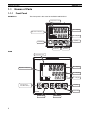
Front Panel
E5CN/CN-U
The front panel is the same for the E5CN and E5CN-U.
Temperature unit
No. 1 display
Operation indicators
No. 2 display
Up Key
Level Key
Mode Key
Down Key
E5AN
Temperature unit
SUB1
PV
SUB2
No.1 display
SUB3
Operation indicators
HA
SV
Function Key/
Auto/Manual Key
OUT1
STOP
OUT2
CMW MANU
MV
PF
Down Key
E5AN
2
No. 3 display
Up Key
A/M
Level Key
No. 2 display
Mode Key
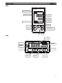
Names of Parts
Section 1-1
E5EN
Operation indicators
SUB1 SUB2
HA
SUB3
PV
Temperature unit
No.1 display
SV
OUT1 STOP
Operation indicators
No.2 display
MV
No.3 display
OUT2 CMW MANU
Up Key
Mode Key
Function Key/
Auto/Manual Key
PF
Level Key
A/M
E5EN
Down Key
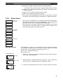
E5GN
No. 1 display
Temperature
unit
Operation
indicators
Operation
indicators
No. 2 display
Level Key
Mode Key
Down Key
Up Key
3
Names of Parts
1-1-2
Section 1-1
Explanation of Indicators
No. 1 Display
Displays the process value or parameter name.
Lights for approximately one second during startup.
No. 2 Display
Displays the set point, parameter operation read value, or the variable input
value.
Lights for approximately one second during startup.
The set point will flash during autotuning.
No. 3 Display
(E5AN/EN Only)
Displays MV, soak time remaining, or multi SP.
Lights for approximately one second during startup.
A 2-level display is set when shipped from the factory.
A 3-level display is activated if parameters are initialized.
Operation Indicators
1,2,3...
1. SUB1 (Sub 1)
Lights when the function set for the Auxiliary Output 1 Assignment parameter is ON.
SUB2 (Sub 2)
Lights when the function set for the Auxiliary Output 2 Assignment parameter is ON.
SUB3 (Sub 3) (E5AN/EN Only)
Lights when the function set for the Auxiliary Output 3 Assignment parameter is ON.
2. HA (Heater Burnout, Heater Short Alarm, Heater Overcurrent Detection
Output Display)
Lights when a heater burnout, heater short alarm, or heater overcurrent
occurs.
3. OUT1 (Control Output 1)
Lights when the control output function assigned to control output 1 turns
ON. For a current output, however, OFF for a 0% output only.
OUT2 (Control Output 2) (Excluding the E5GN)
Lights when the control output function assigned to control output 2 turns
ON. For a current output, however, OFF for a 0% output only.
4. STOP
Lights when operation is stopped.
During operation, this indicator lights when operation is stopped by an
event or by key input using the RUN/STOP function.
5. CMW (Communications Writing)
Lights when communications writing is enabled and is not lit when it is disabled.
6. MANU (Manual Mode)
Lights when the auto/manual mode is set to manual mode.
7.
Temperature Unit
(Key)
Lights when settings change protect is ON (i.e., when the U and D Keys
are disabled by protected status.)
The temperature unit is displayed when parameters are set to display a temperature. The display is determined by the currently set value of the Temperature Unit parameter. °c indicates °C and °f indicates °F.
This indicator flashes during ST operation. It is OFF on models with linear
inputs.
4
Names of Parts
1-1-3
Section 1-1
Using the Keys
This section describes the basic functions of the front panel keys.
PF (Function (Auto/
Manual)) Key
(E5AN/EN Only)
This is a function key. When it is pressed for at least 1 second, the function set
in the PF Setting parameter will operate.
O Key
Press this key to move between setting levels. The setting level is selected in
the following order: operation level: adjustment level, initial setting level, communications setting level.
M Key
Press this key to change parameters within a setting level.
Example: When A-M (auto/manual) is selected in the PF Setting parameter
(initial value: A-M), the key operates as an auto/manual switch, switching
between Auto Mode and Manual Mode. If the key is pressed for more than 1
second (regardless of key release timing), the mode will switch.
The parameters can be reversed by holding down the key (moving one per
second in reverse order).
U Key
Each press of this key increments the value displayed on the No. 2 display or
advances the setting. Holding the key down speeds up the incrementation.
D Key
Each press of this key decrements values displayed on the No. 2 display or
reverses the setting. Holding the key down speeds up the incrementation.
O + M Keys
Press these keys to change to the protect level. For details on operations
involving holding these keys down simultaneously, refer to 1-3 Setting Level
Configuration and Key Operations.
O + U Keys
O + D Keys
To restrict set value changes (in order to prevent accidental or incorrect operations), these key operations require simultaneously pressing the O key
along with U or D key. This applies only to the parameter for the password to
move to protect level.
5
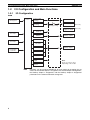
I/O Configuration and Main Functions
1-2
Section 1-2
I/O Configuration and Main Functions
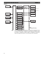
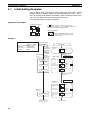
1-2-1
I/O Configuration
E5CN
Temperature input
or analog input
Control
section
Control output
(heating)
Control output 1
Control output
(cooling)
Control output 2
(See note.)
External power
supply for ES1B
(See note.)
Heating/cooling
Alarm 3
CT1 input
Alarm 2
Auxiliary output 2
Alarm 1
CT2 input
HB alarm
HS alarm
Auxiliary output 1
Event inputs
2 channels
OC alarm
Input error
Program end
output
Communications
function
Note
6
Note:
Press one of these keys,
depending on the model.
Functions can be assigned individually for each output by changing the set
values for the Control Output 1 Assignment, the Control Output 2 Assignment,
the Auxiliary Output 1 Assignment, and the Auxiliary Output 2 Assignment
parameters in the advanced function setting level.
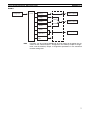
I/O Configuration and Main Functions
Section 1-2
E5CN-U
Control
section
Temperature input
or analog input
Control output
(heating)
Control output
(cooling)
Control output 1
Heating/
cooling
Alarm 3
Auxiliary output 2
Standard
Alarm 2
Alarm 1
Auxiliary output 1
Input error
Program end
output
Note
Functions can be assigned individually for each output by changing the set
values for the Control Output 1 Assignment, the Auxiliary Output 1 Assignment, and the Auxiliary Output 2 Assignment parameters in the advanced
function setting level.
7
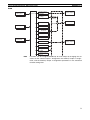
I/O Configuration and Main Functions
Section 1-2
E5AN/EN
Temperature input
or analog input
Control
section
Control output
(heating)
Control output
(cooling)
Control output 1
Heating/cooling
Control output 2
External power
supply for ES1B
Alarm 3
(See note.)
(See note.)
Alarm output 3
CT1 input
Alarm 2
Alarm output 2
Alarm 1
CT2 input
HB alarm
HS alarm
Event inputs 1 and
2 (2 channels)
Alarm output 1
OC alarm
Input error
Program end
output
Communications
function
Note
8
Note:
Press one of these keys,
depending on the model.
Functions can be assigned individually to each output by changing the set values for the Control Output 1 Assignment, Control Output 2 Assignment, Auxiliary Output 1 Assignment, Auxiliary Output 2 Assignment, and Auxiliary
Output 3 Assignment parameters in the advanced function setting level.
I/O Configuration and Main Functions
Section 1-2
E5GN
Control
section
Temperature input
or analog input
Control output
(heating)
Control output
(cooling)
Control output 1
Heating/
cooling
Auxiliary output 1
Alarm 1
Standard
CT1 input
HB alarm
HS alarm
OC alarm
Input error
Event inputs
2 channels
Alarm 2
Auxiliary output 2
Alarm 3
Program end
output
Communications
function
Note
Functions can be assigned individually for each output by changing the set
values for the Control Output 1 Assignment, the Auxiliary Output 1 Assignment, and the Auxiliary Output 2 Assignment parameters in the advanced
function setting level.
9
I/O Configuration and Main Functions
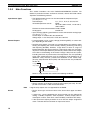
1-2-2
Section 1-2
Main Functions
This section introduces the main E5CN/CN-U/AN/EN/GN functions. For
details on particular functions and how to use them, refer to SECTION 3 Basic
Operation and following sections.
Input Sensor Types
• The following input sensors can be connected for temperature input
(i.e., E5_N-@@@@T):
Thermocouple:
K, J, T, E, L, U, N, R, S, B, W, PLII
Infrared temperature sensor:
ES1B
10 to 70°C, 60 to 120°C, 115 to 165°C,
140 to 260°C
Platinum resistance thermometer: Pt100, JPt100
Analog input:
0 to 50 mV
• Inputs with the following specifications can be connected for analog input
(i.e., E5_N-@@@@L):
Current input: 4 to 20 mA DC, 0 to 20 mA DC
Voltage input: 1 to 5 VDC, 0 to 5 V DC, 0 to 10 V DC
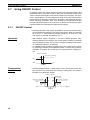
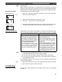
Control Outputs
• A control output can be a relay, voltage (for driving SSR), or current output, depending on the model.
• Long-life relay outputs (see note) use semiconductors for switching when
closing and opening the circuit, thereby reducing chattering and arcing
and improving durability. However, if high levels of noise or surge are
imposed between the output terminals, short-circuit faults may occasionally occur. If the output becomes permanently shorted, there is the danger
of fire due to overheating of the heater. Design safety into the system,
including measures to prevent excessive temperature rise and spreading
of fire. Take countermeasures such as installing a surge absorber. As an
additional safety measure, provide error detection in the control loop.
(Use the Loop Burnout Alarm (LBA) and HS alarm that are provided for
the E5@N.)
Varistor
Long-life
relay output
Inductive
load
1
Varistor
2
Select a surge absorber that satisfies the following conditions.
Voltage used
100 to 120 VAC
200 to 240 VAC
Varistor voltage
240 to 270 V
440 to 470 V
Surge resistance
1,000 A min.
• Always connect an AC load to a long-life relay output (see note). The output will not turn OFF if a DC load is connected.
Note
Alarms
Long-life relay outputs are not supported for the E5GN.
• Set the alarm type and alarm value or the alarm value upper and lower
limits.
• If necessary, a more comprehensive alarm function can be achieved by
setting a standby sequence, alarm hysteresis, auxiliary output close in
alarm/open in alarm, alarm latch, alarm ON delay, and alarm OFF delay.
• If the Input Error Output parameter is set to ON, the output assigned to
alarm 1 function will turn ON when an input error occurs.
10
I/O Configuration and Main Functions
Section 1-2
Control Adjustment
• Optimum PID constants can be set easily by performing AT (auto-tuning)
or ST (self-tuning).
Event Inputs
• With the E53-CN@B@N2 for the E5CN or the E5AN/EN-@M@-500-N with
the E53-AKB for the E5AN/EN, the following functions can be executed
using event inputs: switching set points (multi-SP, 4 points max.), switching RUN/STOP, switching between automatic and manual operation, starting/resetting the program, inverting direct/reverse operation, 100% AT
execute/cancel, 40% AT execute/cancel, setting change enable/disable,
and canceling the alarm latch.
Heater Burnout, HS Alarm,
and Heater Overcurrent
• With the E53-CN@H@N2 or E53-CN@HH@N2 for the E5CN, or the
E5AN/EN-@@H@-500-N or E5AN/EN-@@HH@-500-N, the heater burnout
detection function, HS alarm function, and heater overcurrent detection
function can be used.
Communications
Functions
• Communications functions utilizing CompoWay/F (See note 1.), SYSWAY
(See note 2.), or Modbus (See note 3.) can be used.
RS-485 Interface
Use the E53-CN@03N2 for the E5CN or the E53-EN03 for the E5AN/
EN.
RS-232C Interface
Use the E53-EN01 for the E5AN/EN.
Note
(1) CompoWay/F is an integrated general-purpose serial communications
protocol developed by OMRON. It uses commands compliant with the
well-established FINS, together with a consistent frame format on
OMRON Programmable Controllers to facilitate communications between personal computers and components.
(2) SYSWAY communications do not support alarm 3.
(3) Modbus is a communications control method conforming to the RTU
Mode of Modbus Protocol. Modbus is a registered trademark of
Schneider Electric.
(4) The E5CN and E5CN-U do not support the RS-232C interface.
External Power Supply for
ES1B
Note
Transfer Output
The E5AN-@P@-N or E5EN-@P@-N with the E53-CN@P@N2 can be used as
the power supply for ES1B Infrared Temperature Sensors.
The E5GN does not provide a power supply for an ES1B Infrared Temperature Sensor.
A transfer output for 4 to 20 mA can be used with the E5AN/E5EN-@@F.
For E5@N-C@@ models (models without “F” in the model number), the current output can be used as a simple transfer output.
11
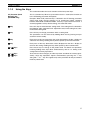
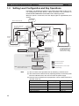
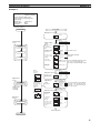
Setting Level Configuration and Key Operations
1-3
Section 1-3
Setting Level Configuration and Key Operations
Parameters are divided into groups, each called a level. Each of the set values (setting items) in these levels is called a parameter. The parameters on
the E5CN/CN-U/AN/EN/GN are divided into the following 9 levels.
When the power is turned ON, all of the display lights for approximately one
second.
Power ON
Start in manual mode.
Start in automatic mode.
Press the O Key or the
PF Key for at least 1 s.
(See note 4.)
Operation
Level
Adjustment
Level
Press the
O Key less than 1 s.
a-m
Manual
mode
(See
note
3.)
Press the O Key
for at least 3 s while
a-m is displayed.
(a-m will flash after
1st second.)
PF Key
(See note 5.)
(See note 4.)
Manual
Control Level
Press the PF Key
for at least 1 s.
(See
note 1.)
Press the
O Key for
at least 1 s.
Control stops.
PF Key
(See note 5.)
Monitor/Setting
Item Level
c
25
Press the
O+ M
Keys for at
least 1 s.
25
100
Press the O Key for at
least 3 s. (Display will flash
after 1st second.)
100
Protect Level
Communications Setting
Level
Initial Setting
Level
Press the
O Key for less than 1 s.
Press the O Key
for at least 1 s.
Press the
O+ M
Keys for at
least 3 s.
c
(Display
will flash
after 1st
second.)
Note The time taken to move
to the protect level can
be adjusted by changing the "Move to protect level time" setting.
Input password while
amoV is displayed. (Set
value −169)
Advanced Function
Setting Level
Control in progress
Input password.
Control stopped
Not displayed for some models
Note: Not described in this manual.
Please refer to H156
Note
Calibration Level
(See
note 2.)
Level change
(1) You can return to the operation level by executing a software reset.
(2) You cannot move to other levels by operating the keys on the front panel
from the calibration level. You must turn OFF the power supply.
(3) From the manual control level, key operations can be used to move to the
operation level only.
Level
Protect level
Operation level
Adjustment level
Manual control level
Monitor/setting item level
Initial setting level
12
Control in progress
Can be set.
Can be set.
Can be set.
Can be set.
Can be set.
---
Control stopped
----------Can be set.
Setting Level Configuration and Key Operations
Level
Advanced function setting level
Calibration level
Communications setting level
Section 1-3
Control in progress
Control stopped
--Can be set.
--Can be set.
--Can be set.
Of these levels, the initial setting level, communications setting level,
advanced function setting level, and calibration level can be used only
when control is stopped. Control outputs are stopped when any of
these four levels is selected.
(4) When the PF Setting is set to A-M in models with a PF Key (E5AN/EN)
(5) When the PF Setting is set to PFDP in models with a PF Key (E5AN/EN)
Protect Level
• To switch to the protect level from the operation level, the adjustment
level, or the monitor/setting item level, simultaneously hold down the O
and M Keys for at least 3 seconds. (See note.) This level is for preventing
unwanted or accidental modification of parameters. Protected levels will
not be displayed, and so the parameters in that level cannot be modified.
Note
Operation Level
The key pressing time can be changed in Move to Protect Level parameter (advanced function setting level).
• The operation level is displayed when the power is turned ON. You can
move to the protect level, initial setting level, or adjustment level from this
level.
• Normally, select this level during operation. While operation is in progress,
items such as the PV and manipulated variable (MV) can be monitored,
and the set points, alarm values, and alarm upper and lower limits can be
monitored and changed.
Adjustment Level
• To move to the adjustment level, press the O Key once (for less than 1 s).
• This level is for entering set values and offset values for control. In addition to AT (auto-tuning), communications write enable/disable switching,
hysteresis settings, multi-SP settings, and input offset parameters, it
includes HB alarm, HS alarm, OC alarm, and PID constants. From the
adjustment level, it is possible to move to the top parameter of the initial
setting level, protect level, or operation level.
Monitor/Setting Item Level
• To switch to the monitor/setting item level, press the PF Key from the
operation level or adjustment level. The contents set for monitor/setting
items 1 to 5 can be displayed. You can move from the monitor/setting item
level to the operation level or initial setting level. (This level is supported
by the E5AN and E5EN only.)
Manual Control Level
• When the O Key is pressed for at least 3 seconds from the operation
level's auto/manual switching display, the manual control level will be displayed. (The MANU indicator will light.)
• When the PF Setting is set to A-M (auto/manual) and the PF Key is
pressed for more than one second from the operation level or adjustment
level, the manual control level will be displayed (E5AN and E5EN only.)
• This is the level for changing the MV in manual mode.
• To return to the operation level, press the O Key for at least one second.
It is also possible to return to the operation level by pressing the PF Key
for more than one second when the PF Setting is set to A-M.
13
Setting Level Configuration and Key Operations
Initial Setting Level
• To move to the initial setting level from the operation level or the adjustment level, press the O Key for at least 3 seconds. The PV display
flashes after one second. This level is for specifying the input type and
selecting the control method, control period, setting direct/reverse operation, setting the alarm types, etc. You can move to the advanced function
setting level or communications setting level from this level. To return to
the operation level, press the O Key for at least one second. To move to
the communications setting level, press the O Key for less than one second.
(When moving from the initial setting level to the operation level, all the
indicators will light.)
Note
Advanced Function
Setting Level
Section 1-3
Pressing the O Key for at least 3 seconds in the operation level's
auto/manual switching display will move to the manual control level,
and not the initial setting level.
• To move to the advanced function setting level, set the Initial Setting/Communications Protect parameter in the protect level to 0 and then, in the initial setting level, input the password (−169).
• From the advanced function setting level, it is possible to move to the calibration level or to the initial setting level.
• This level is for setting the automatic display return time and standby
sequence, and it is the level for moving to the user calibration and other
functions.
Communications Setting
Level
1-3-1
• To move to the communications setting level from the initial setting level,
press the O Key once (for less than 1 s). When using the communications function, set the communications conditions in this level. Communicating with a personal computer (host computer) allows set points to be
read and written, and manipulated variables (MV) to be monitored.
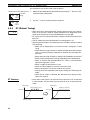
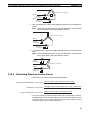
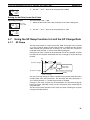
Selecting Parameters
• Within each level, the parameter is changed in order (or in reverse order)
each time the M Key is pressed. (In the calibration level, however, parameters cannot be changed in reverse order.)
14
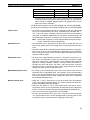
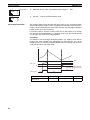
Communications Function
Section 1-4
Moves in order after M key
is pressed (if key is
released within 1 s).
While the M key is being held
down, the parameter will move
each second in reverse order.
Parameter 1
M
Parameter 2
Parameter 2
After M key has
been held down
for 2 s.
M
Parameter 3
Parameter 3
After M key
is pressed
Hold down the M key
during this interval.
After M key has
been held down
for 1 s.
Parameter 4
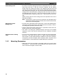
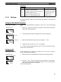
1-3-2
Saving Settings
• If you press the M Key at the final parameter, the display returns to the
top parameter for the current level.
• To change parameter settings, specify the setting using the U or D Key,
and either leave the setting for at least two seconds or press the M Key.
This saves the setting.
• When another level is selected after a setting has been changed, the contents of the parameter prior to the change is saved.
• When you turn the power OFF, you must first save the settings (by pressing the M Key). The settings are sometimes not changed by merely
pressing the U or D Keys.
1-4
Communications Function
The E5CN/AN/EN/GN are provided with a communications function that
enables parameters to be checked and set from a host computer. If the communications function is required, use the E53-CN@03N2 with the E5CN, or
the E53-EN03 or E53-EN01 with the E5AN/EN/GN. For details on the communications function, see the separate Communications Manual Basic Type.
Use the following procedure to move to the communications setting level.
1,2,3...
1. Press the O Key for at least three seconds to move from the operation level to the initial setting level.
2. Press the O Key for less than one second to move from the initial setting
level to the communications setting level.
3. Select the parameters as shown below by pressing the M Key.
4. Press the U or D Key to change the parameter setting.
15
Communications Function
Section 1-4
psel
Protocol Setting
cwf
M
u-no
Communications Unit No.
1
M
bps
Communications Baud Rate
9.6
M
len
Communications Data Length
7 (See note.)
M
sbit
Communications Stop Bits
2 (See note.)
M
prty
Communications Parity
even
M
sdwt
Send Data Wait Time
20
M
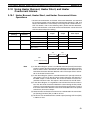
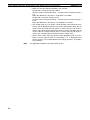
Note
Setting Communications
Data
Parameter name
Protocol Setting
Symbol
psel
Communications
Unit No.
Communications
Baud Rate
Communications
Data Length
Communications
Stop Bits
Communications
Parity
Send Data Wait
Time
u-no
16
The Protocol Setting parameter is displayed only when CompoWay/F communications are being used.
Match the communications specifications of the E5CN/AN/EN/GN and the
host computer. If a 1:N connection is being used, ensure that the communications specifications for all devices in the system (except the communications
Unit No.) are the same.
Setting (monitor) value
CompoWay/F (SYSWAY),
Modbus
0 to 99
Selection symbols
cwf, mod
1.2, 2.4, 4.8, 9.6, 19.2, 38.4.
57.6
len
1.2, 2.4, 4.8, 9.6, 19.2,
38.4, 57.6
7, 8
sbit
1, 2
prty
None, Even, Odd
sdwe
0 to 99
bps
none, even, odd
Default
CompoWay/F
(SYSWAY)
1
Unit
None
None
9.6
kbps
7
Bits
2
Bits
Even
None
20
ms
Insulation Block Diagrams
1-5
Section 1-5
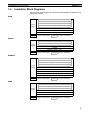
Insulation Block Diagrams
The insulation block diagrams for the E5CN, E5AN, E5EN, and E5GN are provided in this section.
E5CN
Power
supply
Input, CT input, Q outputs (outputs 1 and 2)
Communications and events
External power supply
C output
R output
Y output
Auxiliary outputs 1 and 2
: Reinforced insulation
: Functional insulation
E5CN-U
Input and Q output (output 1)
C output
Power
supply
R output
Y output
Auxiliary outputs 1 and 2
: Reinforced insulation
: Functional insulation
E5AN/EN
Input, CT input, and Q output (output 1)
Communications and events
External power supply and Q output (output 2)
C output and transfer output
Power
supply
R output
Y output
Auxiliary output 1
Auxiliary output 2
Auxiliary output 3
: Reinforced insulation
: Functional insulation
E5GN
Power
supply
Input, CT input, Q output (output 1)
Communications and events
C output
R output
Auxiliary output 1
Auxiliary output 2
: Reinforced insulation
: Functional insulation
17
Insulation Block Diagrams
18
Section 1-5
SECTION 2
Preparations
This section describes the work required to prepare the E5GN, E5CN, E5EN and E5AN Digital Temperature Controllers
for installation. For operation and wiring details refer to the datasheet (H03E and H04E).
2-1
2-2
Installation. . . . . . . . . . . . . . . . . . . . . . . . . . . . . . . . . . . . . . . . . . . . . . . . . . . .
20
2-1-1
Mounting. . . . . . . . . . . . . . . . . . . . . . . . . . . . . . . . . . . . . . . . . . . . . .
20
2-1-2
Removing the Temperature Controller from the Case . . . . . . . . . . .
22
Using the Support Software Port . . . . . . . . . . . . . . . . . . . . . . . . . . . . . . . . . .
26
19
Installation
2-1
2-1-1
Section 2-1
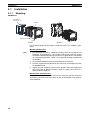
Installation
Mounting
E5CN/CN-U
E53-COV17
Terminal Cover
Adapter
Waterproof packing
Panel
E5CN
E5CN-U
For the Wiring Socket for the E5CN-U, order the P2CF-11 or P3GA-11 separately.
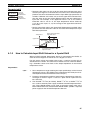
Mounting to the Panel
1,2,3...
1. For waterproof mounting, waterproof packing must be installed on the
Controller. Waterproofing is not possible when group mounting several
Controllers. Waterproof packing is not necessary when there is no need for
the waterproofing function. There is no waterproof packing included with
the E5CN-U.
2. Insert the E5CN/E5CN-U into the mounting hole in the panel.
3. Push the adapter from the terminals up to the panel, and temporarily fasten
the E5CN/E5CN-U.
4. Tighten the two fastening screws on the adapter. Alternately tighten the
two screws little by little to maintain a balance. Tighten the screws to a
torque of 0.29 to 0.39 N·m.
Mounting the Terminal Cover
For the E5CN, make sure that the “UP” mark is facing up, and then attach the
E53-COV17 Terminal Cover to the holes on the top and bottom of the Temperature Controller.
20
Installation
Section 2-1
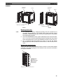
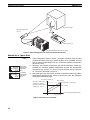
E5AN/EN
Mounting
Bracket
Panel
Mounting
Bracket
Panel
Terminal Cover
(E53-COV16)
Terminal Cover
(E53-COV16)
Waterproof packing
Waterproof packing
E5AN
E5EN
Mounting to the Panel
1,2,3...
1. For waterproof mounting, waterproof packing must be installed on the
Controller. Waterproofing is not possible when group mounting several
Controllers. Waterproof packing is not necessary when there is no need for
the waterproofing function.
2. Insert the E5AN/E5EN into the square mounting hole in the panel (thickness: 1 to 8 mm). Attach the Mounting Brackets provided with the product
to the mounting grooves on the top and bottom surfaces of the rear case.
3. Use a ratchet to alternately tighten the screws on the top and bottom
Mounting Brackets little by little to maintain balance, until the ratchet turns
freely.
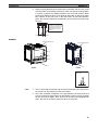
Mounting the Terminal Cover
Slightly bend the E53-COV16 Terminal Cover to attach it to the terminal block
as shown in the following diagram. The Terminal Cover cannot be attached in
the opposite direction.
Slightly bend the
E53-COV16
Terminal Cover in
the direction shown
by the arrows to
attach it to the
terminal block.
Enlarged Illustration of Terminal Section
21
Installation
Section 2-1
E5GN
Mounting to the Panel
1,2,3...
1. For waterproof mounting, waterproof packing must be installed on the
Controller. Waterproofing is not possible when group mounting several
Controllers.
Waterproof packing is not necessary when there is no need for the waterproofing function.
2. Insert the E5GN into the mounting hole in the panel.
3. Push the adapter from the terminals up to the panel, and temporarily fasten
the E5GN.
4. Tighten the two fastening screws on the adapter. Alternately tighten the
two screws little by little to maintain a balance.Tighten the screws to a
torque of 0.29 to 0.39 N·m.
Panel
Adapter
Waterproof packing
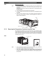
2-1-2
E5GN
Removing the Temperature Controller from the Case
The Temperature Controller can be removed from the case to perform maintenance without removing the terminal leads. This is possible for only the E5CN,
E5AN, and E5EN, and not for the E5CN-U or E5GN. Check the specifications
of the case and Temperature Controller before removing the Temperature
Controller from the case.
E5CN
Tool insertion hole
(1)
Flat-blade screwdriver
(Unit: mm)
20 min.
(2)
(3)
0.4
2.0
(1)
1,2,3...
1. Insert a flat-blade screwdriver into the two tool insertion holes (one on the
top and one on the bottom) to release the hooks.
2. Insert the flat-blade screwdriver in the gap between the front panel and
rear case, and pull out the front panel slightly. Hold the top and bottom of
the front panel and carefully pull it out toward you, without applying unnecessary force.
22
Installation
Section 2-1
3. When inserting the body of the Temperature Controller into the case, make
sure the PCBs are parallel to each other, make sure that the sealing rubber
is in place, and press the E5CN toward the rear case into position. While
pushing the E5CN into place, push down on the hooks on the top and bottom surfaces of the rear case so that the hooks are securely locked in
place. Be sure that electronic components do not come into contact with
the case.
Make sure the PCBs are
parallel to each other, and
then press the body of the
Temperature Controller
toward the rear case into
position.
Bottom View of the E5CN
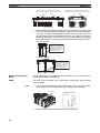
E5AN/EN
Tool insertion hole
Tool insertion hole
(1)
(1)
(2)
(2)
(3)
(3)
(1)
E5AN
(1)
E5EN
Flat-blade screwdriver
(Unit: mm)
0.4
1,2,3...
2.0
5.0
1. Insert a flat-blade screwdriver into the two tool insertion holes (one on the
top and one on the bottom) to release the hooks.
2. Insert the flat-blade screwdriver in the gap between the front panel and
rear case (two on the top and two on the bottom), and use it to pry and pull
out the front panel slightly. Then, pull out on the front panel gripping both
sides. Be sure not to impose excessive force on the panel.
23
Installation
Section 2-1
Gap between the Front Panel and Rear Case
Four gaps, two on the top and two on the bottom
Gap between the Front Panel and Rear Case
Four gaps, two on the top and two on the bottom
Top View of E5EN
Top View of E5AN
3. When inserting the body of the Temperature Controller into the case, make
sure the PCBs are parallel to each other, make sure that the sealing rubber
is in place, and press the E5AN/EN toward the rear case until it snaps into
position. While pressing the E5AN/EN into place, press down on the hooks
on the top and bottom surfaces of the rear case so that the hooks securely
lock in place. Make sure that electronic components do not come into contact with the case.
Make sure the PCBs are
parallel to each other, and
then press the body of the
Temperature Controller
toward the rear case until
it snaps into position.
Bottom View of the E5EN
Make sure the PCBs are
parallel to each other, and
then press the body of the
Temperature Controller
toward the rear case until
it snaps into position.
Bottom View of the E5AN
Removing the Terminal
Block
The terminal block can be removed from the E5GN. It is not possible for the
E5CN, E5AN, E5EN, and E5CN-U.
E5GN
The body of the Controller can be replaced by removing the terminal block
from the E5GN.
1,2,3...
1. Insert a flat-blade screwdriver into the tool holes (one on the top and one
on the bottom) to release the hooks. Do not apply excessive force.
Terminal hole
20 min.
Flat-blade screwdriver
(Unit: mm)
0.4
20
2. Pull the terminal block out while the hooks are released.
24
Installation
Section 2-1
Note
The method for removing the terminal block is the same for both screw terminal blocks and screwless clamp terminal blocks.
Do not connect a different type of terminal block to a Controller. For example,
do not replace a screw terminal block with a screwless clamp terminal block.
The temperature indication accuracy will decrease.
25
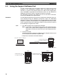
Using the Support Software Port
2-2
Section 2-2
Using the Support Software Port
Use the communications port for Support Software to connect the personal
computer to the Temperature Controller when using EST2-2C-MV4 CXThermo or a version of CX-Thermo higher than 4.00, or other Support Software. The E5GN is supported from CX-Thermo version 4.2. The E58-CIFQ1
USB-Serial Conversion Cable is required to make the connection.
For information concerning the models that can be used with CX-Thermo,
contact your OMRON sales representative.
Procedure
Use the following procedure to connect the Temperature Controller to the personal computer using the USB-Serial Conversion Cable. The USB-Serial
Conversion Cable is used to communicate with the COM port of the personal
computer. To perform communications using USB-Serial Conversion Cable,
set the communications port (COM port) number to be used for the software
to the COM port assigned to the Cable.
1,2,3...
1. Turn ON the power to the Temperature Controller.
Note
If the Cable is connected when the power to the Temperature Controller is OFF, power will be supplied from the personal computer
and impose a load on the internal circuits of the Temperature Controller.
2. Connect the Cable.
Connect the personal computer’s USB port with the Support Software port
on the Temperature Controller using the Cable.
• Temperature Controller Connection Method
E5CN/CN-U
Personal computer's USB port
Communications port
for Support Software
E58-CIFQ1
Bottom view of E5CN
E5EN
E5AN
Communications port
for Support Software
Communications port
for Support Software
Bottom view of E5AN
Bottom view of E5EN
26
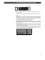
Using the Support Software Port
Section 2-2
Setup Tool port
E5GN
Side View of the E5GN
Note
Hold the connector when inserting or disconnecting the Cable.
3. Install the driver.
Install the driver to enable the Cable to be used with the personal computer.
• Installation
When the Cable is connected with the personal computer, the OS detects
the product as a new device. At this time, install the driver using the installation wizard. For details on installation methods, refer to the user’s manual for the E58-CIFQ1 USB-Serial Conversion Cable.
4. Setting Setup Tool Communications Conditions
Set the communications port (COM port) number to be used for the CXThermo Setup Tool to the COM port number assigned to the USB-Serial
Conversion Cable.
Refer to the E58-CIFQ1 USB-Serial Conversion Cable Instruction Manual
and Setup Manual for details on how to check the COM port assigned to
the USB-Serial Conversion Cable.
The communications conditions for Setup Tool COM ports are fixed as
shown in the table below. Set the communications conditions for the CXThermo Setup Tool according to the following table.
Parameter
Communications Unit No.
Communications baud rate
Communications data length
Communications stop bits
Communications parity
Set value
01
38.4 (kbps)
7 (bits)
2 (bits)
Even
27
Using the Support Software Port
28
Section 2-2
SECTION 3
Basic Operation
This section describes the basic operation of the E5GN, E5CN, E5EN and E5AN Digital Temperature Controllers,
including key operations to set parameters and descriptions of display elements based on specific control examples.
3-1
Initial Setting Examples . . . . . . . . . . . . . . . . . . . . . . . . . . . . . . . . . . . . . . . . .
30
3-2
Setting the Input Type . . . . . . . . . . . . . . . . . . . . . . . . . . . . . . . . . . . . . . . . . . .
32
3-2-1
Input Type . . . . . . . . . . . . . . . . . . . . . . . . . . . . . . . . . . . . . . . . . . . . .
32
3-3
Selecting the Temperature Unit. . . . . . . . . . . . . . . . . . . . . . . . . . . . . . . . . . . .
34
Temperature Unit . . . . . . . . . . . . . . . . . . . . . . . . . . . . . . . . . . . . . . .
34
3-4
Selecting PID Control or ON/OFF Control . . . . . . . . . . . . . . . . . . . . . . . . . .
34
3-5
Setting Output Specifications . . . . . . . . . . . . . . . . . . . . . . . . . . . . . . . . . . . . .
34
3-5-1
Control Periods . . . . . . . . . . . . . . . . . . . . . . . . . . . . . . . . . . . . . . . . .
34
3-5-2
Direct and Reverse Operation. . . . . . . . . . . . . . . . . . . . . . . . . . . . . .
35
3-5-3
Assigned Output Functions. . . . . . . . . . . . . . . . . . . . . . . . . . . . . . . .
36
Setting the Set Point (SP) . . . . . . . . . . . . . . . . . . . . . . . . . . . . . . . . . . . . . . . .
39
3-6-1
Changing the SP . . . . . . . . . . . . . . . . . . . . . . . . . . . . . . . . . . . . . . . .
39
3-3-1
3-6
3-7
3-8
3-9
Using ON/OFF Control. . . . . . . . . . . . . . . . . . . . . . . . . . . . . . . . . . . . . . . . . .
40
3-7-1
ON/OFF Control. . . . . . . . . . . . . . . . . . . . . . . . . . . . . . . . . . . . . . . .
40
3-7-2
Settings . . . . . . . . . . . . . . . . . . . . . . . . . . . . . . . . . . . . . . . . . . . . . . .
41
Determining PID Constants (AT, ST, Manual Setup) . . . . . . . . . . . . . . . . . . .
42
3-8-1
AT (Auto-tuning) . . . . . . . . . . . . . . . . . . . . . . . . . . . . . . . . . . . . . . .
42
3-8-2
ST (Self-tuning) . . . . . . . . . . . . . . . . . . . . . . . . . . . . . . . . . . . . . . . .
44
3-8-3
RT (Robust Tuning) . . . . . . . . . . . . . . . . . . . . . . . . . . . . . . . . . . . . .
46
3-8-4
Manual Setup . . . . . . . . . . . . . . . . . . . . . . . . . . . . . . . . . . . . . . . . . .
48
Alarm Outputs. . . . . . . . . . . . . . . . . . . . . . . . . . . . . . . . . . . . . . . . . . . . . . . . .
49
3-9-1
Alarm Types . . . . . . . . . . . . . . . . . . . . . . . . . . . . . . . . . . . . . . . . . . .
49
3-9-2
Alarm Values . . . . . . . . . . . . . . . . . . . . . . . . . . . . . . . . . . . . . . . . . .
51
3-10 Using Heater Burnout, Heater Short, and Heater Overcurrent Alarms. . . . . .
53
3-10-1 Heater Burnout, Heater Short, and Heater Overcurrent Alarm Operations 53
3-10-2 Installing Current Transformers (CT). . . . . . . . . . . . . . . . . . . . . . . .
54
3-10-3 Calculating Detection Current Values . . . . . . . . . . . . . . . . . . . . . . .
55
3-10-4 Settings: HB Alarm. . . . . . . . . . . . . . . . . . . . . . . . . . . . . . . . . . . . . .
57
3-10-5 Settings: Heater Short Alarm . . . . . . . . . . . . . . . . . . . . . . . . . . . . . .
58
3-10-6 Settings: Heater Overcurrent Alarm . . . . . . . . . . . . . . . . . . . . . . . . .
59
3-11 Setting the No. 3 Display . . . . . . . . . . . . . . . . . . . . . . . . . . . . . . . . . . . . . . . .
61
3-11-1 PV/SP Display Selection . . . . . . . . . . . . . . . . . . . . . . . . . . . . . . . . .
61
29
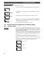
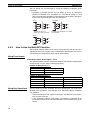
Initial Setting Examples
3-1
Section 3-1
Initial Setting Examples
Initial hardware setup, including the sensor input type, alarm types, control
periods, and other settings, is done using parameter displays. The O and M
Keys are used to switch between parameters, and the amount of time that you
press the keys determines which parameter you move to.
This section describes two typical examples.
Explanation of Examples
Changing Parameters
in-t
0
in-h
100 M
M
A
image means that there are parameters.
Continue pressing the M key to change parameters
until you reach the intended parameter.
in-l
0 M
Changing Numbers
C
cntl
cntl
onof
25
0
onof
Numeric data and selections in each
screen can be changed by using the
U and D keys.
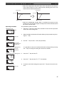
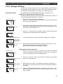
Example 1
Input type:
5 (K thermocouple,
−200°C to 1,300°C)
Control method: ON/OFF control
Alarm type:
2 (upper limit)
Alarm value 1: 20°C (deviation)
Set point:
100°C
Setup Procedure
Power ON
Power ON
An s.err
error will be
displayed if
the power
supply is
turned ON
before the
Initial Setting sensor is
Level
connected.
Operation
Level
C
25 PV/SP
0
Press the O key for
at least 3 s.
Control stops.
Initial Setting
Level
Set input
specifications
Check input type.
Set control
specifications
Check that
control method is
ON/OFF control.
in-t
Input Type: 5
5
M
cntl
onof
M
alt1
Check alarm type.
Set alarm type
ON/OFF
control:
PID
control:
onof
pid
Alarm 1 Type: 2
2
M
Press the O key for
at least 1 s.
Control starts.
Operation
Level
Use the U and
D keys to set the
SP to 100°C.
C
25
100
PV/SP:
100
M
Operation
Level
Set alarm values
Start operation
30
r-s
Confirm that
control is running.
Use the U and
D keys to set the
alarm value to
20°C.
Running
run Stopped:
M
C
al-1
20
run
stop
Alarm Value 1: 20
M
Start operation.
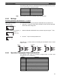
Initial Setting Examples
Section 3-1
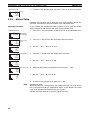
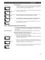
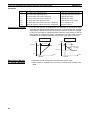
Example 2
Input type:
9 (T thermocouple,
−200°C to 400°C)
Control method: PID control
PID constants found using autotuning (AT).
Alarm type:
2 upper limit
Alarm value 1: 30°C
Set point:
150°C
Setup Procedure
Power ON
Power ON
Operation Level
C
25
PV/SP
0
Press the O key for
at least 3 s.
Initial Setting
Level
Control stops.
Initial Setting
Level
Use the U and
D keys to
select the input
type.
in-t
Set control
specifications
Use the U and
D keys to select
PID control.
cntl
st
Set alarm type
Use the U and
D keys to set ST
to OFF.
Set input
specifications
9
pid
off
M
Check the
control period.
25
150
Adjustment
Level
AT execution
(When PID
control is
selected)
C
The set point
flashes during
auto-tuning (AT)
execution.
After AT is
stopped
at
off
During AT
execution
at
Operation
Level
Set alarm value
onof
For PID, set pid.
pid
on
When ON, self-tuning
operates.
off
cp
Control Period
20
(Heat)
alt1
Alarm 1 Type: 2
It is recommended that 20 seconds
be set for a relay output and 2
seconds for an SSR voltage output.
2
M
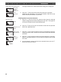
Press the O key for
at least 1 s.
Control starts.
Operation Level
Use the U and
D keys to set
the SP to 150°C.
C
25
PV/SP:
150
26
150
ON/OFF
control:
PID
control:
To execute
ST:
To cancel
ST:
20 (Unit: Seconds)
M
Check the
alarm type.
C
9
M
M
PV/SP
after AT is
stopped
Input Type:
Press the O key
(for less than 1 s).
Adjustment
Level
To execute
100%AT: at-2
execute
at To
40%AT:
at-1
Execute AT.
off To cancel
AT:
Operation Level
Confirm that
the set point
is 150°C.
C
off
To execute 100% AT (auto-tuning),
select at-2. To execute 40% AT,
select at-1. To cancel AT, select
off: (AT cancel).
Press the O key
(for less than 1 s).
25
PV/SP
150
at-1
M
Confirm that
control is
running.
Use the U and
D keys to set
the alarm value
to 30°C.
150
r-s
run
M
C
al-1
30
Running
Stopped
run
stop
Alarm
Value 1
30
M
Start operation.
Start operation
31
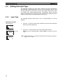
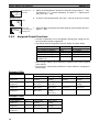
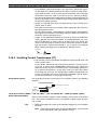
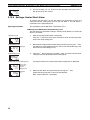
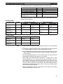
Setting the Input Type
3-2
Section 3-2
Setting the Input Type
The Controller supports four input types: platinum resistance thermometer,
thermocouple, infrared temperature sensor, and analog inputs. Set the input
type that matches the sensor that is used. In the product specifications, there
are models with thermocouple/resistance thermometer inputs (universal
inputs) and models with analog input. The settings differ depending on the
model. Check to make sure which model you are using.
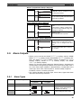
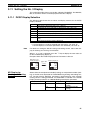
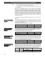
3-2-1
Input Type
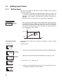
The following example shows how to set a K thermocouple for −20.0 to
500.0°C.
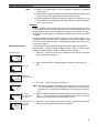
Operating Procedure
1. Press the O Key for at least three seconds to move from the operation
level to the initial setting level.
Operation Level
C
25
0
Initial Setting Level
in-t
Input Type
2. Press the U Key to enter the set value of the desired sensor.
When you use a K thermocouple (−20.0 to 500.0°C), enter 6 as the set
value.
5
in-t
6
32
Hint: The key operation is saved two seconds after the change, or by pressing the O or M Key.
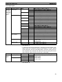
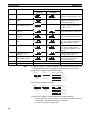
Setting the Input Type
Section 3-2
List of Input Types
Input type
Controllers Platinum resistance
thermometer
with Thermocouple/
Resistance
Thermometer Multiinput
Thermocouple
Specifications Set value
Pt100
0
1
2
JPt100
3
4
K
5
J
T
E
L
U
N
R
S
B
Infrared temperature 10 to 70°C
sensor ES1B
60 to 120°C
115 to 165°C
140 to 260°C
Analog input
0 to 50 mV
Thermocouple
W
PLII
6
7
8
9
10
11
12
13
14
15
16
17
18
19
20
21
22
23
24
25
Input temperature setting range
−200 to 850 (°C)/−300 to 1,500 (°F)
−199.9 to 500.0 (°C)/−199.9 to 900.0 (°F)
0.0 to 100.0 (°C)/0.0 to 210.0 (°F)
−199.9 to 500.0 (°C)/−199.9 to 900.0 (°F)
0.0 to 100.0 (°C)/0.0 to 210.0 (°F)
−200 to 1,300 (°C)/−300 to 2,300 (°F)
−20.0 to 500.0 (°C)/0.0 to 900.0 (°F)
−100 to 850 (°C)/−100 to 1,500 (°F)
−20.0 to 400.0 (°C)/0.0 to 750.0 (°F)
−200 to 400 (°C)/−300 to 700 (°F)
−199.9 to 400.0 (°C)/−199.9 to 700.0 (°F)
−200 to 600 (°C)/−300 to 1,100 (°F)
−100 to 850 (°C)/−100 to 1,500 (°F)
−200 to 400 (°C)/−300 to 700 (°F)
−199.9 to 400.0 (°C)/−199.9 to 700.0 (°F)
−200 to 1,300 (°C)/−300 to 2,300 (°F)
0 to 1,700 (°C)/0 to 3,000 (°F)
0 to 1,700 (°C)/0 to 3,000 (°F)
100 to 1,800 (°C)/300 to 3,200 (°F)
0 to 90 (°C)/0 to 190 (°F)
0 to 120 (°C)/0 to 240 (°F)
0 to 165 (°C)/0 to 320 (°F)
0 to 260 (°C)/0 to 500 (°F)
Either of the following ranges, by scaling:
−1,999 to 9,999
−199.9 to 999.9
0 to 2,300 (°C)/0 to 3,200 (°F)
0 to 1,300 (°C)/0 to 2,300 (°F)
• The default is 5.
• If a platinum resistance thermometer is mistakenly connected while a setting for other than a platinum resistance thermometer is in effect, S.ERR
will be displayed. To clear the S.ERR display, check the wiring and then
turn the power OFF and back ON. Make sure that the setting of the input
type parameter agrees with the sensor that is connected.
Input type
Models with Current input
analog
input
Voltage input
Specifications Set value
4 to 20 mA
0
0 to 20 mA
1
1 to 5 V
2
0 to 5 V
3
0 to 10 V
4
Input temperature setting range
Either of the following ranges, by scaling:
−1,999 to 9,999
−199.9 to 999.9
−19.99 to 99.99
−1.999 to 9.999
• The default is 0.
33
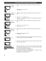
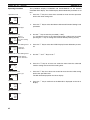
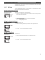
Selecting the Temperature Unit
3-3
3-3-1
Section 3-3
Selecting the Temperature Unit
Temperature Unit
• Either °C or °F can be selected as the temperature unit.
• Set the temperature unit in the Temperature Unit parameter of the initial
setting level. The default is c (°C).
Operating Procedure
1. Press the O Key for at least three seconds to move from the operation
level to the initial setting level.
Operation Level
C
The following example shows how to select °C as the temperature unit.
30
0
Initial Setting Level
in-t
Input Type
5
d-u
Temperature
Unit
2. Select the Temperature Unit parameter by pressing the M Key.
Press the U or D Key to select either °C or °F.
c: °C
f: °F
3. To return to the operation level, press the O Key for at least one second.
c
3-4
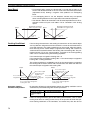
Selecting PID Control or ON/OFF Control
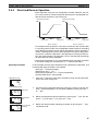
Two control methods are supported: 2-PID control and ON/OFF control.
Switching between 2-PID control and ON/OFF control is executed by means
of the PID ON/OFF parameter in the initial setting level. When this parameter
is set to pid, 2-PID control is selected, and when set to onof, ON/OFF control, is selected. The default is onof.
2-PID Control
PID control is set by AT (auto-tuning), ST (self-tuning), or manual setting.
For PID control, set the PID constants in the Proportional Band (P), Integral
Time (I), and Derivative Time (D) parameters.
ON/OFF Control
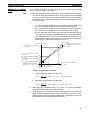
3-5
3-5-1
In ON/OFF control, the control output is turned ON when the process value is
lower than the current set point, and the control output is turned OFF when
the process value is higher than the current set point (reverse operation).
Setting Output Specifications
Control Periods
cp
c-cp
Control Period
(Heating)
Control Period
(Cooling)
• Set the output periods (control periods). Though a shorter period provides
better control performance, it is recommended that the control period be
set to 20 seconds or longer for a relay output to preserve the service life
of the relay. After the settings have been made in the initial setup, readjust
the control period, as required, by means such as trial operation.
• Set the control periods in the Control Period (Heating) and Control Period
(Cooling) parameters in the initial setting level. The default is 20 seconds.
• The Control Period (Cooling) parameter is used only for heating/cooling
control.
• When control output 1 is used as a current output, Control Period (Heating) cannot be used.
34
Setting Output Specifications
3-5-2
Section 3-5
Direct and Reverse Operation
• Direct operation increases the manipulated variable whenever the process value increases. Reverse operation decreases the manipulated variable whenever the process value increases.
Manipulated variable
Manipulated variable
100%
100%
0%
0%
Low
Set Value
temperature
High
temperature
Direct operation
Low
Set Value
temperature
High
temperature
Reverse operation
For example, when the process value (PV) is lower than the set point (SP)
in a heating control system, the manipulated variable increases according
to the difference between the PV and SP. Accordingly, reverse operation is
used in a heating control system. Direct operation is used in a cooling control system, in which the operation is the opposite of a heating control system. The Control Output 1 Assignment is set to o (control output (heating))
for either direct or reverse operation.
• Direct/reverse operation is set in the Direct/Reverse Operation parameter
in the initial setting level. The default is or-r (reverse operation).
Operating Procedure
In this example, the input type, temperature unit, direct/reverse operation, and
control period (heat) parameters are checked.
Input type = s (K thermocouple)
Temperature unit = c (°C)
Direct/reverse operation = or-r (reverse operation)
Control period (heat) = 20 (seconds)
1. Press the O Key for at least three seconds to move from the operation
level to the initial setting level.
Operation Level
C
30
0
Initial Setting Level
in-t
Input Type
2. The input type is displayed. When the input type is being set for the first
time, s (K thermocouple) is set. To select a different sensor, press the U
or D Key.
5
d-u
Temperature
Unit
3. Select the Temperature Unit parameter by pressing the M Key. The default is c (°C). To select f (°F), press the U Key.
Control Period
(Heating)
4. Select the Control Period (Heating) parameter by pressing the M Key.
The default is 20.
c
cp
20
35
Setting Output Specifications
orev
Direct/Reverse
Operation
or-r
30
5. Select the Direct/Reverse Operation parameter by pressing the M Key.
The default is or-r (reverse operation). To select or-d (direct operation), press the U Key.
6. To return to the operation level, press the O Key for at least one second.
Operation Level
C
Section 3-5
PV/SP
0
amov
0
3-5-3
7.
Move to Advanced Function
Setting Level
Select the Move to Advanced Function Setting Level parameter by pressing the M Key.
Assigned Output Functions
• Function assignments can be changed by changing the settings for control and auxiliary output assignments.
• The default function assignments for each output are shown below.
Parameter name
Control Output 1 Assignment
Control Output 2 Assignment
Auxiliary Output 1 Assignment
Auxiliary Output 2 Assignment
Auxiliary Output 3 Assignment
(E5AN/EN only)
Symbol
out1
out2
sub1
sub2
sub3
Initial status
Control output (heating)
Not assigned.
Alarm 1
Alarm 2
Alarm 3
• Refer to pages 240 to 242 of H156 for the functions that can be assigned
to the outputs.
• Each output is automatically initialized as shown below by changing the
control mode.
Example: E5CN
Parameter name
Control Output 1
Assignment
Control Output 2
Assignment
Auxiliary Output 1
Assignment
Auxiliary Output 2
Assignment
Symbol
out1
out2
sub1
sub2
Without control output 2
Standard
Heating/cooling
Control output
Control output
(heating)
(heating)
Not assigned.
Not assigned.
(See note 1.)
(See note 1.)
Alarm 1
Alarm 1
(See note 2.)
(See note 2.)
Alarm 2
Control output
(See note 3.)
(cooling)
(See note 3.)
Example: E5GN
Parameter name
Control Output 1
Assignment
Auxiliary Output 1
Assignment
Auxiliary Output 2
Assignment
36
Symbol
out1
sub1
sub2
Standard
Control output
(heating)
Alarm 1
(See note 2.)
Alarm 2
Heating/cooling
Control output
(heating)
Control output
(cooling)
Alarm 2
With control output 2
Standard
Heating/cooling
Control output
Control output
(heating)
(heating)
Not assigned.
Control output
(cooling)
Alarm 1
Alarm 1
(See note 2.)
(See note 2.)
Alarm 2
Alarm 2
Setting Output Specifications
Note
Section 3-5
(1) There is no control output 2 and no parameter assignment is displayed
for that output.
(2) The Auxiliary Output 1 Assignment parameter becomes the program end
output unless the Program Pattern parameter is set to OFF.
(3) For the E5AN/EN, the Auxiliary Output 3 Assignment parameter is set as
the control output for cooling. (The Auxiliary Output 2 Assignment parameter is set for alarm 2).
■ Alarms
It will be specified in this section when an alarm must be assigned, i.e., when
an alarm must be set for the Control Output 1 or 2 Assignment parameters, or
for the Auxiliary Output 1 to 3 Assignment parameters. For example, if alarm 1
is set for the Control Output 1 Assignment parameter, then alarm 1 has been
assigned.
Assigning a work bit to either control output 1 or 2 or to auxiliary output 1 to 3
is also considered to be the same as assigning an alarm. For example, if work
bit 1 is set for the Auxiliary Output 1 Assignment parameter, then alarms 1 to 3
have been assigned.
Operating Procedure
Operation Level
C
25
PV/SP
This procedure sets the following control and auxiliary output assignments.
Control output 1: Control output (heating); Control output 2: Control output
(cooling); Auxiliary output 1: Alarm 1; Auxiliary output 2: Alarm 2
1. Press the O Key for at least three seconds to move from the operation
level to the initial setting level.
100
Initial Setting Level
in-t
Input Type
2. Select the Standard or Heating/Cooling parameter by pressing the M
Key.
5
Initial Setting Level
Standard or
5-hc Heating/Cooling
stnd
Initial Setting Level
5-hc
h-c
amov
0
3. Press the U Key to set the parameter to h-c.
Note The following output assignments do not need to be set because they
are set automatically by changing the control mode, but they are
shown here as a reference for checking the assignments for each output.
4.
Select
the Move to Advanced Function Setting Level parameter by pressMove to Ading the M Key. (For details on moving between levels, refer to 1-3 (page
vanced Function
Setting Level
14) Moving to the Advanced Function Setting Level.)
Advanced Function Setting Level
Parameter
init Initialization
5. Press the D Key to enter the password (“−169”), and move from the initial
setting level to the advanced function setting level.
off
37
Setting Output Specifications
Advanced Function Setting Level
Control Output
out1 1 Assignment
Section 3-5
6. Select the Control Output 1 Assignment parameter by pressing the M
Key.
o
7. Press the U or D Key to set o.
(The default is o.)
out1
o
Advanced Function Setting Level
Control Output
out2 2 Assignment
8. Select the Control Output 2 Assignment parameter by pressing the M
Key.
c-o
9. Press the U or D Key to set c-o.
(When h-c is selected for the Standard or Heating/Cooling parameter,
the setting will be c-o.)
out2
c-o
Advanced Function Setting Level
Auxiliary Output
sub1 1 Assignment
10. Select the Auxiliary Output 1 Assignment parameter by pressing the M
Key.
alm1
11. Press the U or D Key to set alm1.
(The default is alm1.)
sub1
alm1
12. Select the Auxiliary Output 2 Assignment parameter by pressing the M
Key.
Auxiliary Output
Advanced Function Setting Level
sub2
2 Assignment
alm2
13. Press the U or D Key to set alm2.
(The default is alm2.)
sub2
alm2
Input Type
14. Press the O Key for at least one second to move from the advanced
function setting level to the initial setting level.
PV/SP
15. Press the O Key for at least one second to move from the initial setting
level to the operation level.
Initial Setting Level
in-t
5
Operation Level
C
25
100
Auxiliary Output
Opening or Closing in
Alarm
• When “close in alarm” is set, the status of the auxiliary output is output
unchanged. When “open in alarm” is set, the status of the auxiliary output
function is reversed before being output.
• Each auxiliary output can be set independently.
• These settings are made in the Auxiliary Output 1 to 3 Open in Alarm
parameters (advanced function setting level).
• The default is n-o: Close in Alarm.
38
Setting the Set Point (SP)
Section 3-6
• When “open in alarm” is set for the alarm 1 output, the open in alarm status is also applied to heater burnout, HS alarm, heater overcurrent, and
input error outputs.
Auxiliary output
functions 1 to 3
Close in Alarm ON
OFF
Open in Alarm ON
OFF
Auxiliary
output
ON
OFF
OFF
ON
Indicators
(SUB1 to SUB3)
Lit
Not lit
Lit
Not lit
• The alarm output will turn OFF (i.e., the relay contacts will open) when
power is interrupted and for about two seconds after the power is turned
ON regardless of the setting of the Auxiliary Output 1 to 3 Open in Alarm
parameter.
3-6
Setting the Set Point (SP)
Operation Level
C
20
The operation level is displayed when the power is turned ON. The process
value (PV) is at the top of the display, and the set point (SP) is at the bottom.
0
Operation Level
C
20
0
50.0
3-6-1
For Controllers that support a No. 3 display (E5AN/E5EN), the contents set
in the PV/SP Display Screen Selection parameter (advanced function setting
level) are displayed below the PV and SP.
The MV is displayed as the default. For details, refer to 3-11 Setting the No.
3 Display.
Changing the SP
• The set point cannot be changed when the Operation/Adjustment Protect
parameter is set to 3. For details, refer to 4-9 of H156 Using the Key Protect Level.
• To change the set point, press the U or D Key in the Process Value/Set
Point parameter (in the operation level), and set the desired set value. The
new set point is selected two seconds after you have specified the new
value.
• Multi-SP is used to switch between two or four set points. For details, refer
to 4-5 of H156 Using Event Inputs for details.
Operating Procedure
Operation Level
C
30
In this example, the set point is changed from 0°C to 200°C.
1. Normally, the Process Value/Set Point parameter is displayed. The set
point is 0°C.
0
C
30
2. Use the U and D Keys to set the set point to 200°C.
200
39
Using ON/OFF Control
3-7
Section 3-7
Using ON/OFF Control
In ON/OFF control, the control output turns OFF when the temperature being
controlled reaches the preset set point. When the manipulated variable turns
OFF, the temperature begins to fall and the control turns ON again. This operation is repeated over a certain temperature range. At this time, how much the
temperature must fall before control turns ON again is determined by the Hysteresis (Heating) parameter. Also, what direction the manipulated variable
must be adjusted in response to an increase or decrease in the process value
is determined by the Direct/Reverse Operation parameter.
3-7-1
ON/OFF Control
• Switching between 2-PID control and ON/OFF control is performed using
the PID ON/OFF parameter in the initial setting level. When this parameter is set to pid, 2-PID control is selected, and when it is set to onof, ON/
OFF control is selected. The default is onof.
Hysteresis
• With ON/OFF control, hysteresis is used to stabilize operation when
switching between ON and OFF. The control output (heating) and control
output (cooling) functions are set in the Hysteresis (Heating) and Hysteresis (Cooling) parameters, respectively.
• In standard control (heating or cooling control), the setting of the Hysteresis (Heating) parameter in the adjustment level is used as the hysteresis
regardless of whether the control type is heating control or cooling control.
Reverse operation
Hysteresis (heating)
ON
PV
OFF
Set point
Three-position
Control
• In heating/cooling control, a dead band (an area where both control outputs are 0) can be set to either the heating or cooling side. This makes it
possible to use 3-position control.
Reverse operation
Dead band
Hysteresis (heating)
Hysteresis (cooling)
ON
Heating
side
Cooling
side
PV
OFF
Set point
40
Using ON/OFF Control
Section 3-7
Parameters
Symbol
s-hc
cntl
orev
c-db
hys
chys
3-7-2
Parameter: level
Application
Standard or Heating/Cooling: Initial setting level
PID ON/OFF: Initial setting level
Direct/Reverse Operation: Initial setting level
Dead Band: Adjustment level
Hysteresis (Heating): Adjustment level
Hysteresis (Cooling): Adjustment level
Specifying control method
Specifying control method
Specifying control method
Heating/cooling control
ON/OFF control
ON/OFF control
Settings
To execute ON/OFF control, set the Set Point, PID ON/OFF, and Hysteresis
parameters.
Setting the PID ON/OFF Parameter
Operating Procedure
Operation Level
C
25
PV
Confirm that the PID ON/OFF parameter is set to onof in the initial setting
level.
1. Press the O Key for at least three seconds to move from the operation
level to the initial setting level.
100
Initial Setting Level
in-t
Input Type
cntl
PID ON/OFF
2. The Input Type parameter is displayed in the initial setting level.
5
3. Select the PID ON/OFF parameter by pressing the M Key.
onof
4. Check that the set value is onof (i.e., the default).
5. To return to the operation level, press the O Key for at least one second.
Next, set the set point value.
Setting the SP
Operating Procedure
1. Select the Process Value/Set Point parameter in the operation level.
Operation Level
C
25
In this example, the set point is set to 200. The set value (i.e., the SP) is
shown at the bottom of the display.
PV/SP
100
C
25
200
2. Use the U and D Keys to set the SP. (In this example, it is set to 200.)
The new set value can be saved by pressing the M Key, or it will go into
effect after two seconds have elapsed.
Next, set the hysteresis.
41
Determining PID Constants (AT, ST, Manual Setup)
Section 3-8
Setting the Hysteresis
Operating Procedure
1. Press the O Key to move from the operation level to the adjustment level.
Operation Level
C
25
Set the hysteresis to 2.0°C.
PV
200
Adjustment Level
1.adj
C
hys
Adjustment
Level Display
Hysteresis
(Heating)
2. The Adjustment Level Display parameter will be displayed in the adjustment level.
3. Select the Hysteresis (Heating) parameter by pressing the M Key.
1.0
C
hys
2.0
4. Press the U and D Keys to set the hysteresis (2.0 in this example). Either press the M Key or wait for at least two seconds after setting the hysteresis value to confirm the setting.
5. To return to the operation level, press the O Key.
3-8
3-8-1
Determining PID Constants (AT, ST, Manual Setup)
AT (Auto-tuning)
at
• When AT is executed, the optimum PID constants for the set point at that
time are set automatically. A method (called the limit cycle method) for
forcibly changing the manipulated variable and finding the characteristics
of the control object is employed.
• Either 40% AT or 100% AT can be selected depending on the width of MV
variation in the limit cycle. In the AT Execute/Cancel parameter, specify
at-2 (100% AT) or at-1 (40% AT). To cancel AT, specify off (AT cancel).
• Only 100% AT can be executed for heating and cooling control.
• AT cannot be executed when control has stopped or during ON/OFF control.
• The results of AT are reflected in the Proportional Band (P), Integral Time
(I), and Derivative Time (D) parameters in the adjustment level.
Adjustment Level
C
p
Proportional Band
i
Integral Time
d
Derivative Time
(0
233
40
42
Determining PID Constants (AT, ST, Manual Setup)
AT Operations
Section 3-8
AT is started when either at-2 (100% AT) or at-1 (40% AT) is specified for
the AT Execute/Cancel parameter. During execution, the AT Execute/Cancel
parameter on the No. 1 display flashes. When AT ends, the AT Execute/Cancel parameter turns OFF, and the No. 1 display stops flashing.
AT Execute/Cancel
at
at
off
No. 1 display
at-2
100% AT execution in progress
If you move to the operation level during AT execution, the No. 2 display
flashes to indicate that AT is being executed.
PV/SP
C
C
25
100
25
100
No. 2 display
AT execution in progress
Only the Communications Writing, RUN/STOP, AT Execution/Cancel, and Program Start parameters can be changed during AT execution. Other parameters cannot be changed.
AT Calculated Gain
The AT Calculated Gain parameter sets the gain for when PID values are calculated using AT. When emphasizing response, decrease the set value. When
emphasizing stability, increase the set value.
AT Hysteresis
The AT Hysteresis parameter sets the hysteresis when switching ON and OFF
for the limit cycle operation during auto-tuning.
Limit Cycle MV Amplitude
The Limit Cycle MV Amplitude parameter sets the MV amplitude for limit cycle
operation during auto-tuning.
Note
■
This setting is disabled for 100% AT.
40% AT
The width of MV variation in the limit cycle can be changed in the Limit Cycle
MV Amplitude parameter, but the AT execution time may be longer than for
100% AT. The limit cycle timing varies according to whether the deviation (DV)
at the start of auto-tuning execution is less than 10% FS.
Deviation ≥ 10% FS
PV
Deviation < 10% FS
PV
Limit Cycle MV
Amplitude 40%
Limit Cycle MV
Amplitude 40%
SP
SP
Deviation:
10% FS
Deviation:
10% FS
Time
AT started
AT ended
Time
AT started
AT ended
43
Determining PID Constants (AT, ST, Manual Setup)
■
Section 3-8
100% AT
Operation will be as shown in the following diagram, regardless of the deviation (DV) at the start of AT execution. To shorten the AT execution time, select
100% AT.
PV
Limit Cycle MV
Amplitude 100%
SP
Time
AT started
Note
Operating Procedure
AT ended
The Limit Cycle MV Amplitude parameter is disabled.
This procedure executes 40%AT.
1. Press the O Key to move from the operation level to the adjustment level.
Adjustment Level
AT Execute/
at Cancel
off
2. Press the U Key to select at-1. The No. 1 display for AT Execute/Cancel
will flash during AT execution.
at
at-1
3. off will be displayed when AT ends.
at
off
4. To return to the operation level, press the O Key.
Operation Level
C
25
PV
0
3-8-2
ST (Self-tuning)
st
ST (self-tuning) is a function that finds PID constants by using step response
tuning (SRT) when Controller operation begins or when the set point is
changed.
Once the PID constants have been calculated, ST is not executed when the
next control operation is started as long as the set point remains unchanged.
ST (self-tuning) is enabled when the ST parameter is set to ON in the initial
setting level.
When the ST function is in operation, be sure to turn the power supply of the
load connected to the control output ON simultaneously with or before starting
Controller operation.
When executing self-tuning, turn ON power for the load (e.g., heater) at the
same time as or before supplying power to the Digital Temperature Controller.
If power is turned ON for the Digital Temperature Controller before turning ON
power for the load, self-tuning will not be performed properly and optimum
control will not be achieved.
44
Determining PID Constants (AT, ST, Manual Setup)
Note
Operating Procedure
PID Constants
When control characteristics are already known, PID constants can be set
directly to adjust control. PID constants are set in the Proportional Band (P),
Integral Time (I), and Derivative Time (D) parameters in the adjustment level.
This procedure executes self-tuning (ST).
Input Type
1. Press the O Key for at least three seconds to move from the operation
level to the initial setting level.
ST
2. Select the ST parameter by pressing the M Key.
Initial Setting Level
in-t
Section 3-8
5
st
3. Press the U Key to select on. ON is the default.
on
4. To return to the operation level, press the O Key for at least one second.
The temperature display flashes during self-tuning (ST) execution.
Operation Level
C
25
PV
100
Startup Conditions
Self-tuning by step response tuning (SRT) is started when the following conditions are met after program execution is started and the set point is changed.
At start of operation
1. The set point at the start of operation
differs from the set point when the previous SRT was executed. (See note 1.)
2. The difference between the temperature at the start of operation and the set
point is greater both of the following:
(Present proportional band × 1.27 +
4°C) and the ST stable range.
3. The temperature at the start of operation is lower than the set point during
reverse operation, and is larger than
the set point during direct operation.
4. There is no reset from input errors.
Note
When set point is changed
1. The new set point differs from the set
point used when the previous SRT was
executed. (See note 1.)
2. The set point change width is greater
both of the following: (Present proportional band × 1.27 + 4°C) and the ST
stable range.
3. During reverse operation, the new set
point is larger than the set point before
the change; and during direct operation, the new set point is smaller than
the set point before the change.
4. The temperature is stable. (See note
2.) (Equilibrium with the output amount
at 0% when the power is turned ON is
also all right.) (See note 3.)
(1) The previous SRT-implemented set point is the set point that was used for
calculating the PID constants for the previous SRT.
(2) In this state, the measurement point is within the ST stable range.
(3) In this state, the change width of the PV every 60 seconds is within the
ST stable range or less.
In the following instances, PID constants are not changed by self-tuning (ST)
for the present set point.
1,2,3...
1. When the PID constants have been changed manually with ST set to ON.
2. When auto-tuning (AT) has been executed.
ST Stable Range
Operating Procedure
The ST stable range determines the condition under which ST (self-tuning)
functions.
45
Determining PID Constants (AT, ST, Manual Setup)
Section 3-8
This procedure sets the ST stable range to 20.0°C.
Advanced Function Setting Level
C
ST Stable
st-b Range
1. Select the ST Stable Range parameter by pressing the M Key in the advanced function setting level.
1%0
C
2. Use the U Key to set the parameter to 20.0°C.
st-b
2*0
3-8-3
RT (Robust Tuning)
• When AT or ST is executed with RT selected, PID constants are automatically set that make it hard for control performance to degenerate even
when the characteristics of the controlled object are changed.
rt
• RT can be set in the advanced function setting level when PID control has
been set.
• The RT mode cannot be selected while an analog input is set.
• Selecting the RT mode in the following cases will help to prevent hunting
from occurring.
• When the set temperature is not constant and is changed in a wide
range
• When there are large variations in ambient temperatures due to factors
such as seasonal changes or differences between day and night temperatures
• When there are large variations in ambient wind conditions and air flow
• When heater characteristics change depending on the temperature
• When an actuator with disproportional I/O, such as a phase-controltype power regulator, is used
• When a rapidly heating heater is used
• When the control object or sensor has much loss time
• When hunting occurs in normal mode for any reason
• PID constants are initialized to the factory settings by switching to RT
mode.
• When the RT mode is selected, the derivative time setting unit becomes the second.
RT Features
• Even when hunting occurs for PID constants when AT or ST is executed
in normal mode, it is less likely to occur when AT or ST is executed in RT
mode.
Temperature
Temperature
Much hunting occurs.
Set value
Start of control
46
Hunting is reduced.
Set value
Time
Start of control
Time
Determining PID Constants (AT, ST, Manual Setup)
Section 3-8
• When the temperature (PV) falls short of the set point for the PID constants when using AT or ST in normal mode, executing AT or ST in RT
mode tends to improve performance.
Temperature
Temperature
Set value
Set value
Start of control
Time
Start of control
Time
• When the manipulated variable (MV) is saturated, the amount of overshooting may be somewhat higher in comparison to PID control based on
AT or ST in normal mode.
Operating Procedure
Operation Level
C
25
PV/SP
This procedure selects RT mode.
1. Press the O Key for at least three seconds to move from the operation
level to the initial setting level.
100
Initial Setting Level
in-t
Input Type
2. Select the Move to Advanced Function Setting Level parameter by pressing the M Key.
5
Initial Setting Level
3. Use the D Key to enter “−169” (the password).
Move to Ad-
Function
amov vanced
Setting Level
0
Advanced Function Setting Level
Parameter
init Initialization
It is possible to move to the advanced function setting level by pressing
the M Key or leaving the setting for at least two seconds.
off
Advanced Function Setting Level
rt
4. Press the M Key to select rt.
RT
off
5. Press the U Key to select on. off is the default.
rt
on
Initial Setting Level
in-t
Input Type
6. To return to the initial setting level, press the O Key for at least one second.
5
47
Determining PID Constants (AT, ST, Manual Setup)
7. To return to the operation level, press the O Key for at least one second.
Operation Level
C
25
Section 3-8
PV/SP
100
3-8-4
Manual Setup
Individual PID constants can be manually set in the Proportional Band, Integral Time, and Derivative Time parameters in the adjustment level.
Operating Procedure
In this example, the Proportional Band parameter is set to 10.0, the Integral
Time parameter to 250, and the Derivative Time parameter to 45.
1. Press the O Key to move from the operation level to the adjustment level.
Adjustment Level
Adjustment
l.adj Level Display
C
p
Proportional
Band
2. Press the M Key to select the proportional band” parameter.
8.0
C
3. Use the U and D Keys to set 10.0.
p
10.0
i
Integral Time
4. Press the M Key to select the Integral Time parameter.
233
5. Use the U and D Keys to set 250.
i
250
d
Derivative Time
6. Select the Derivative Time operation by pressing the M Key.
40
7. Use the U and D Keys to set 45.
d
45
8. To return to the operation level, press the O Key.
Note
48
Proportional Action
When PID constants I (integral time) and D (derivative time) are set to 0, control is executed according to proportional action. As the default, the center
value of the proportional band becomes the set point.
Related parameter: Manual reset value (adjustment level)
Alarm Outputs
Section 3-9
When P (Proportional Band) Is Adjusted
Increased
Set
value
The curve rises gradually, and a long
stabilization time is created, but overshooting is prevented.
Set
value
Overshooting and hunting occur, but
the set value is quickly reached and the
temperature stabilizes.
Decreased
When I (Integral Time) Is Adjusted
Increased
Decreased
It takes a long time to reach the set
point.
It takes time to achieve a stable state,
but overshooting, undershooting, and
hunting are reduced.
Overshooting and undershooting occur.
Hunting occurs.
The Controller starts up faster.
Set
value
Set
value
When D (Derivative Time) Is Adjusted
Increased
Decreased
3-9
Overshooting, undershooting, and stabilization times are reduced, but fine
hunting occurs on changes in the curve
itself.
Overshooting and undershooting
increase, and it takes time to return to
the set point.
Set
value
Set
value
Alarm Outputs
• Alarms can be used by the E5CN-@2@@@ (2 auxiliary outputs), E5AN/
E5EN-@1@@@ (1 auxiliary output), E5AN/E5EN-@3@@@ (3 auxiliary outputs), the E5CN-@1@@@U (1 auxiliary output), the E5CN-@2@@@U (2
auxiliary outputs), E5GN-@1@@@ (1 auxiliary output), and E5GN@2@@@ (2 auxiliary outputs).
Alarms can also be used by setting the Control Output 1 Assignment or
Control Output 2 Assignment parameter to any of the alarms from alarm 1
to 3. The alarm output condition is determined by a combination of the
alarm type, alarm value, alarm hysteresis, and the standby sequence.
For details, refer to 4-2 Alarm Hysteresis.
• This section describes the Alarm Type, Alarm Value, Upper-limit Alarm
and Lower-limit Alarm parameters.
3-9-1
Set value
Alarm Types
Alarm type
0
Alarm function OFF
1 (See note Upper- and lower-limit
1.)
2
Upper-limit
Alarm output operation
Description of function
When alarm value X When alarm value X
is positive
is negative
Output OFF
No alarm
See note 2.
Set the deviation in the set point by
L H
ON
setting the alarm upper limit (H)
OFF
SP
and alarm lower limit (L).
ON
OFF
X
SP
ON
OFF
X
SP
Set the upward deviation in the set
point by setting the alarm value
(X).
49
Alarm Outputs
Set value
3
Section 3-9
Alarm type
Alarm output operation
When alarm value X When alarm value X
is positive
is negative
Lower-limit
X
ON
OFF
4 (See note Upper- and lower-limit
1.)
range
ON
OFF
5 (See note Upper- and lower-limit
1.)
with standby sequence
ON
OFF
ON
OFF
SP
Set the downward deviation in the
set point by setting the alarm value
(X).
Set the deviation in the set point by
setting the alarm upper limit (H)
and alarm lower limit (L).
A standby sequence is added to
the upper- and lower-limit alarm
(1). (See note 6.)
X
SP
See note 3.
L H
SP
See note 4.
L H
SP
See note 5.
6
7
8
9
10
11
12
13
Upper-limit with standby
sequence
ON
OFF
Lower-limit with standby
sequence
ON
OFF
Absolute-value upperlimit
ON
OFF
Absolute-value lower-limit
Absolute-value upperlimit with standby
sequence
X
LBA (alarm 1 type only)
PV change rate alarm
-----
ON
OFF
SP
X
ON
OFF
0
X
ON
OFF
0
X
ON
OFF
ON
OFF
ON
OFF
SP
ON
OFF
Absolute-value lower-limit
with standby sequence
Note
X
ON
OFF
0
X
ON
OFF
0
Description of function
A standby sequence is added to
the upper-limit alarm (2). (See note
6.)
A standby sequence is added to
the lower-limit alarm (3). (See note
6.)
The alarm will turn ON if the process value is larger than the alarm
value (X) regardless of the set
point.
The alarm will turn ON if the process value is smaller than the
alarm value (X) regardless of the
set point.
X
SP
X
SP
X
0
X
0
A standby sequence is added to
the absolute-value upper-limit
alarm (8). (See note 6.)
X
0
A standby sequence is added to
the absolute-value lower-limit
alarm (9). (See note 6.)
(See note 7.)
Refer to page 52. (See note 8.)
X
0
(1) With set values 1, 4, and 5, the upper- and lower-limit values can be set
independently for each alarm type, and are expressed as “L” and “H.”
(2) Set value: 1 (Upper- and lower-limit alarm)
Case 1
Case 2
Case 3 (Always ON)
H < 0, L < 0
L
H SP
H < 0, L > 0
|H| < |L|
H
SP L H
H > 0, L < 0
|H| > |L|
H
SP
L
H < 0, L > 0
|H| ≥ |L|
L SP
SP H
L
H > 0, L < 0
|H| ≤ |L|
(3) Set value: 4 (Lower limit range)
Case 2
Case 1
Case 3 (Always OFF)
H < 0, L < 0
L
H SP
H < 0, L > 0
|H| < |L|
SP L
H
H
H > 0, L < 0
|H| > |L|
H
SP
L
L SP
SP H L
H < 0, L > 0
|H| ≥ |L|
H > 0, L < 0
|H| ≤ |L|
(4) Set value: 5 (Upper- and lower-limit with standby sequence)
• For the lower-limit alarms in cases 1 and 2 above, the alarm is always
OFF if upper- and lower-limit hysteresis overlaps.
• In case 3, the alarm is always OFF.
50
Alarm Outputs
Section 3-9
(5) Set value: 5 (Upper- and lower-limit with standby sequence)
• The alarm is always OFF if upper- and lower-limit hysteresis overlaps.
(6) Refer to 4-2-1 Standby Sequence for information on the operation of the
standby sequence.
(7) Refer to 4-12 of H156: Loop Burnout Alarm (LBA).
(8) Refer to PV Change Rate Alarm on page 52.
• Set the alarm type independently for each alarm in the Alarm 1 to 3 Type
parameters in the initial setting level. The default is 2 (Upper-limit alarm).
3-9-2
Alarm Values
al1l
Alarm Lower
Limit Value
al2l
• To set the alarm value upper and lower limits for deviation, set the upper
and lower limits in each of the Alarm 1 to 3 Upper Limit, and Alarm 1 to 3
Lower Limit parameters in the operation level.
al3l
al1h
• Alarm values are indicated by “X” in the table on the previous page. When
the upper and lower limits are set independently, “H” is displayed for
upper limit values, and “L” is displayed for lower limit values.
Alarm Upper
Limit Value
al2h
al3h
al-1
Alarm Value
al-2
al-3
Operating Procedure
This procedure sets alarm 1 as an upper-limit alarm. The related parameters
and settings are shown below. The alarm is output when the set point
exceeds 10°C. (In this example, the temperature unit is °C.)
Alarm 1 type = 2 (Upper-limit alarm)
Alarm value 1= 10
Initial Setting Level
1. Press the O Key for at least three seconds to move from the operation
level to the initial setting level.
in-t
Input Type
alt1
Alarm 1 Type
2. Select the Alarm 1 Type parameter by pressing the M Key. Confirm that
the set value is 2. The default value is 2 (Upper-limit alarm).
PV/SP
3. To return to the operation level, press the O Key for at least one second.
5
2
C
25
100
51
Alarm Outputs
C
al-1
Section 3-9
Alarm Value 1
4. Select the Alarm Value 1 parameter by pressing the M Key.
0
C
al-1
5. Use the U Key to set the parameter to 10.
10
PV Change Rate Alarm
The change width can be found for PV input values in any set period. Differences with previous values in each set period are calculated, and an alarm is
output if the result exceeds the alarm value. The PV rate of change calculation
period can be set in units of 250 ms.
If a positive value is set for the alarm value, the PV will operate as a change
rate alarm in the rising direction. If a negative value is set, the PV will operate
as a change rate alarm in the falling direction.
Precaution
If a shorter PV rate of change calculation period is set, outputs set for the PV
change rate alarm function may repeatedly turn ON and OFF for a short
period of time. It is therefore recommended that the PV change rate alarm be
used with the alarm latch turned ON.
PV
Time
Alarm value
0
PV change width for PV rate
of change calculation period
ON
Alarm function
OFF
ON
OFF
Parameter name
Setting range
Unit
PV Rate of Change Calcu- 1 to 999
Sampling cycle
lation Period
52
Default
4 (1 s)
Using Heater Burnout, Heater Short, and Heater Overcurrent Alarms
Section 3-10
3-10 Using Heater Burnout, Heater Short, and Heater
Overcurrent Alarms
3-10-1 Heater Burnout, Heater Short, and Heater Overcurrent Alarm
Operations
• Heater burnout detection and heater overcurrent detection are executed
by measuring heater current while the control output (heating) is ON, and
heater short detection is executed by measuring heater current while it is
OFF. For details, refer to the following table. (Heater burnout detection,
heater short detection, and heater overcurrent detection cannot be used
with the control output for cooling.)
Control output (heating) status
Control output
Operation
(heating)
indicator
ON
Lit
OFF
Not lit
ON
Lit
Power to heater
HB alarm
output
HS alarm
output
Heater overcurrent
alarm output
Yes (Normal) (See note 1.)
No (Heater burnout)
Yes (HS alarm)
No (Normal) (See note 2.)
Normal
OFF
ON
-------
----ON
OFF
---
--------OFF
Heater overcurrent status
(See note 3.)
---
---
ON
Ton
(See note 4.)
Toff
(See note 5.)
ON
Control output (heating)
OFF
Note
(1) In the above diagram, power is considered to be ON (normal) if the heater
current is greater than the heater burnout detection current during the Ton
interval. If the heater is burned out, the measured current decreases and
falls below the heater burnout detection value. The output is then activated as the heater burnout alarm.
(2) In the above diagram, power is considered to be OFF (normal) if the leakage current is less than the HS alarm current during the Toff interval. If
the SSR output is short-circuited, the measured current increases beyond the HS alarm value. The output is then activated as the HS alarm.
(3) In the above diagram, it is regarded as normal when the heater current is
less than the heater overcurrent detection current during the Ton period.
Current is increased when excessive current flows to the heater, causing
the heater overcurrent detection value to be exceeded and an OC (heater
overcurrent) alarm to be output.
(4) Heater burnout and heater overcurrent are not detected if the control output (heating) ON time (Ton) is 100 ms or less.
(5) HS alarms are not detected if the control output (heating) OFF time (Toff)
is 100 ms or less.
53
Using Heater Burnout, Heater Short, and Heater Overcurrent Alarms
Section 3-10
• For Controllers with heater burnout, HS, and heater overcurrent alarms,
an OR output is established between the ALM 1 function and the alarms.
If the ALM1 function is to be used for the heater burnout, HS, and heater
overcurrent alarms only, set 0 as the alarm 1 type (i.e., do not use ALM1).
• Turn the heater power ON simultaneously or before turning ON the E5@N
power. If the heater power is turned ON after turning ON the E5AN power,
the HB alarm will be activated.
• Control is continued even when the heater burnout, HS, or heater overcurrent alarm is active.
• The rated current value may sometimes differ slightly from the actual current flowing to the heater.
Use the Heater Current 1 Value Monitor, Heater Current 2 Value Monitor,
Leakage Current 1 Monitor, and Leakage Current 2 Monitor parameters to
check the actual current being used.
• If there is little difference between the current in normal and abnormal
states, detection may become unstable. To stabilize detection, set a current value difference of at least 1.0 A for heaters of less than 10.0 A, and
at least 2.5 A for heaters of 10.0 A or more. If the heater current is too low,
loop the load line several times through a CT, as shown in the diagram
below. Looping it through once will double the detection current.
Load line
CT
3-10-2 Installing Current Transformers (CT)
• This function can be used with E5@N models that have the HB alarm, HS
alarm, and OC alarm.
For the E5CN, connect the CT in advance to terminals 14 and 15 (CT1),
or 13 and 15 (CT2). For the E5AN/E5EN, connect the CT in advance to
terminals 14 and 15 (CT1) or 15 and 16 (CT2). For the E5GN, connect the
CT in advance to terminals 7 and 8 (CT1). Then pass the heater power
line through the CT's hole. For specifications, models and dimensions of
current transformers that can be used with this Controller, refer to Appendix Current Transformer (CT) on page 279 of H156 .
Single-phase Heaters
For single-phase heaters, install the CT in the position shown in the following
diagram.
Load
AC line
Load (such as a heater)
CT
Product
To CT input
Three-phase Heaters (E5AN-@@HH@-N, E5EN-@@HH@-N, and E53-CN@@HHN2 (for E5CN) 3-phase
Heater Detection Models)
When a 3-phase power supply is used, regardless of the types of connecting
lines, two current transformers (CTs) are required to detect heater burnout,
HS, and OC.
1,2,3...
1. Delta connecting lines: Refer to the following diagram for CT installation
positions.
Note
54
Heater voltage fluctuations are not considered here, so be take that
into account when setting the detection current.
Using Heater Burnout, Heater Short, and Heater Overcurrent Alarms
Lo
ad
ad
Lo
AC line
Section 3-10
Load (such as a heater)
Load
Product
To CT input
AC line
CT
Product
To CT input
2. Star connecting lines: Refer to the following diagram for CT installation positions.
Heater voltage fluctuations are not considered here, so be take that
into account when setting the detection current.
Load
Note
Load (such as a heater)
Lo
ad
ad
Lo
AC line
Product
To CT input
CT
CT
Product
To CT input
3. V connecting lines: Refer to the following diagram for CT installation positions.
Heater voltage fluctuations are not considered here, so be take that
into account when setting the detection current.
CT
ad
Product
To CT input
Lo
Note
Load (such as a heater)
ad
Lo
AC line
CT
Product
To CT input
3-10-3 Calculating Detection Current Values
• Calculate the set value using the following equation:
Heater Burnout Detection 1/2 set value = Normal current value + Burnout current value
2
HS Alarm 1/2 set value = Leakage current value (output OFF) + HS current value
2
Heater overcurrent 1/2 set value = Normal current value + Overcurrent value
2
• To set the current for heater burnout when two or more heaters are connected through the CT, use the value from when the heater with the smallest current burns out. If all of the heaters have the same current, use the
value from when any one of them burns out.
55
Using Heater Burnout, Heater Short, and Heater Overcurrent Alarms
Section 3-10
• Make sure that the following conditions are satisfied:
Heater with a current of less than 10.0 A:
(Current value at normal operation) − (Current value at heater burnout) ≥
1A
When the difference is less than 1 A, detection is unstable.
Heater with a current of 10.0 A or more:
(Current value at normal operation) − (Current value at heater burnout) ≥
2.5 A
When the difference is less than 2.5 A, detection is unstable.
• The setting range is 0.1 to 49.9 A. Heater burnout, HS, and heater overcurrent are not detected when the set value is 0.0 or 50.0. When the set
value is 0.0, the heater burnout alarm is always OFF, the HS alarm is
always ON, and the heater overcurrent alarm is always ON. When the set
value is 50.0, the heater burnout alarm is always ON, the HS alarm is
always OFF, and the heater overcurrent alarm is always OFF.
• Set the total current value for normal heater operation to 50 A or less.
When a current value of 55.0 A is exceeded, ffff is displayed in the
Heater Current 1 (or 2) Value Monitor and Leakage Current 1 (or 2) Monitor parameters.
Note
56
For application examples see H156 section 3-10-4
Using Heater Burnout, Heater Short, and Heater Overcurrent Alarms
Section 3-10
3-10-4 Settings: HB Alarm
To activate the heater burnout alarm, set the HB ON/OFF parameter to ON in
the advanced function setting level and set the Heater Burnout Detection 1
and Heater Burnout Detection 2 parameters in the adjustment level.
Operating Procedure
This procedure sets the Heater Burnout Detection 1 parameter to 2.5.
■
Moving to the Advanced Function Setting Level
The Heater Burnout Detection parameter setting is already ON by default, so
set the Heater Burnout Detection 1 parameter.
1. Move to the advanced function setting level.
Press the O Key for at least three seconds to move from the operation
level to the initial setting level.
Operation Level
C
25
PV/SP
100
2. Select Move to Advanced Function Setting Level by pressing the M Key.
(For details on moving between levels, refer to 4-8 of H156 Moving to the
Advanced Function Setting Level.)
Initial Setting Level
in-t
Input Type
5
3. Press the D Key to enter the password (−169), and move from the initial
setting level to the advanced function setting level.
Initial Setting Level
amov
-169
Advanced Function Setting Level
The top parameter in the advanced function setting level is displayed.
to Adinit Moves
vanced Function
Setting Level
off
Heater Burnout
hbu Detection
on
■
Operation Level
C
25
PV/SP
4. Select the Heater Burnout Detection parameter by pressing the M Key.
Check that this parameter is set to ON (the default).
Next, set the Heater Burnout Detection 1 parameter.
Setting Heater Burnout Detection
5. Press the O Key for at least one second to move from the advanced
function setting level to the initial setting level. Press the O key again for
at least one second to move to the operation level.
100
Adjustment Level
6. Press the O Key for less than one second to move from the operation
level to the adjustment level.
Adjustment Level
l.adj Display
ct1
Heater Current
1 Value Monitor
7. Select the Heater Current 1 Value Monitor parameter by pressing the M
Key. Check the current value. Next, set the Heater Burnout Detection 1
parameter.
hb1
Heater Burnout
Detection 1
8. Select the Heater Burnout Detection 1 parameter by pressing the M Key.
Refer to Calculating Detection Current Values on page 55 on when making the settings.
0.0
0.0
57
Using Heater Burnout, Heater Short, and Heater Overcurrent Alarms
Section 3-10
9. For this example, set 2.5. To return to the operation level, press the O
Key for less than one second.
hb1
2.5
3-10-5 Settings: Heater Short Alarm
To activate the HS alarm, set the HS Alarm Use parameter to ON in the
advanced function setting level and set the HS Alarm 1 and HS Alarm 2
parameters in the adjustment level.
Operating Procedure
This procedure sets the HS Alarm 1 parameter to 2.5.
■
Moving to the Advanced Function Setting Level
The HS Alarm Use parameter setting is already ON by default, so set the HS
Alarm 1 parameter.
Operation Level
C
25
PV/SP
1. Move to the advanced function setting level.
Press the O Key for at least three seconds to move from the operation
level to the initial setting level.
100
Initial Setting Level
in-t
Input Type
2. Select Move to Advanced Function Setting Level by pressing the M Key.
(For details on moving between levels, refer to 4-8 of H156 Moving to the
Advanced Function Setting Level.)
5
Initial Setting Level
amov
3. Press the D Key to enter the password (−169), and move from the initial
setting level to the advanced function setting level.
-169
Advanced Function Setting Level
The top parameter in the advanced function setting level is displayed.
Move to the
init Advanced
Function
off
hsu
on
58
Setting Level
HS Alarm
Use
4. Select the HS Alarm Use parameter by pressing the M Key.
Check that this parameter is set to ON (the default).
Next, set the HS Alarm 1 parameter.
Using Heater Burnout, Heater Short, and Heater Overcurrent Alarms
■
25
HS Alarm Settings
5. Press the O Key for at least one second to move from the advanced
function setting level to the initial setting level. Press the O key again for
at least one second to move to the operation level.
Operation Level
C
Section 3-10
PV/SP
100
Adjustment Level
6. Press the O Key for less than one second to move from the operation
level to the adjustment level.
Adjustment Level
l.adj Display
lcr1
Leakage Current 7.
1 Monitor
Select the Leakage Current 1 Monitor parameter by pressing the M Key.
Check the current value. Next, set the HS Alarm 1 parameter.
0.0
hs1
8. Select the HS Alarm 1 parameter by pressing the M Key. Refer to Calculating Detection Current Values on page 55 when setting the values.
HS Alarm 1
50.0
9. For this example, set 2.5. To return to the operation level, press the O
Key for less than one second.
hs1
2.5
3-10-6 Settings: Heater Overcurrent Alarm
To activate heater overcurrent alarm, set the Heater Overcurrent Use parameter to ON in the advanced function setting level and set the Heater Overcurrent Detection 1 and Heater Overcurrent Detection 2 parameters in the
adjustment level.
Operating Procedure
This procedure sets the Heater Overcurrent Detection 1 parameter to 20.0.
■
Moving to the Advanced Function Setting Level
The default setting for the Heater Overcurrent Use parameter is ON, so set
the Heater Overcurrent Detection 1 parameter.
Operation Level
C
25
PV/SP
1. Move to the advanced function setting level.
Press the O Key for at least three seconds to move from the operation
level to the initial setting level.
100
Initial Setting Level
in-t
Input Type
2. Press the M Key to select the Move to Advanced Function Setting Level
parameter. (For details on moving between levels, refer to 4-8 of H156
Moving to the Advanced Function Setting Level.)
5
Initial Setting Level
amov
3. Press the D Key to enter the password (−169), and move from the initial
setting level to the advanced function setting level.
-169
59
Using Heater Burnout, Heater Short, and Heater Overcurrent Alarms
Advanced Function Setting Level
Section 3-10
The top parameter in the advanced function setting level is displayed.
Move to the
init Advanced
Function
off
Setting Level
4. Press the M Key to select the Heater Overcurrent Use parameter.
Check that this parameter is set to ON (the default), and then set the
Heater Overcurrent Detection 1 parameter.
Heater
ocu Overcurrent
Use
on
■
Operation Level
C
25
PV/SP
Setting Heater Overcurrent Detection
5. Press the O Key for at least one second to move from the advanced
function setting level to the initial setting level. Press the O key again for
at least one second to move to the operation level.
100
Adjustment Level
6. Press the O Key for less than one second to move from the operation
level to the adjustment level.
Adjustment Level
l.adj Display
ct1
Heater Current
1 Value Monitor
7. Press the M Key to select the Heater Current 1 Value Monitor parameter.
Check the current value, and then set the Heater Overcurrent Detection
parameter.
oc1
Heater
Overcurrent
Detection 1
8. Press the M Key to select the Heater Overcurrent Detection 1 parameter.
Refer to Calculating Detection Current Values on page 55 when setting
the values.
0.0
50.0
oc1
20.0
60
9. For this example, set 20.0. To return to the operation level, press the O
Key for less than one second.
Setting the No. 3 Display
Section 3-11
3-11 Setting the No. 3 Display
This section describes how to set the No. 3 Display (E5AN/EN). The Multi-SP,
MV, or soak time remain can be displayed on the No. 3 display.
3-11-1 PV/SP Display Selection
The following table shows the set values and display contents for the PV/SP
Display selection.
Set value
0
1
2
3
4
5
6
7
Display contents
Only PV/SP is displayed (with no No. 3 display.)
PV/SP/Multi-SP and PV/SP/MV are displayed in order. (See note.)
PV/SP/MV and PV/SP/Multi-SP are displayed in order. (See note.)
Only PV/SP/Multi-SP is displayed.
Only PV/SP/MV is displayed. (See note.)
PV/SP/Multi-SP and PV/SP/Soak time remain are displayed in order.
PV/SP/MV and PV/SP/Soak time remain are displayed in order. (See
note.)
Only PV/SP/Soak time remain is displayed.
• A 2-level display is set when shipped from the factory. (set value: 0)
A 3-level display is activated if parameters are initialized. (set value: 4)
Note
For details on setting the MV for heating and cooling control, refer to MV Display for Heating and Cooling Control below.
When 1, 2, 5, or 6 is selected, press the M Key to display the next value set
for the PV/SP display (display 2).
Example: When the PV/SP Display Screen Parameter Is Set to 2
Operation Level
PV/SP (Display 1)
C
25
PV/SP (Display 2)
Press the
C
M key
100
50.0
sp0
PV/SP/MV
MV Display for
Heating and Cooling
Control
25
100
PV/SP/Multi-SP
Select either the manipulated variable (heating) or manipulated variable (cooling) as the MV to be displayed for PV/SP/MV during heating and cooling control. The MV Display Selection parameter is displayed only when heating/
cooling control is being performed and PV/SP/MV is selected in the PV/SP
Display Screen parameter or a Monitor/Setting Item Display parameter.
Parameter name
MV Display Selection
Set value
Symbol
O
o
C-O
c-o
Display contents
Manipulated variable
(heating)
Manipulated variable
(cooling)
61
Setting the No. 3 Display
Operating Procedure
Operation Level
C
25
PV/SP
Section 3-11
This procedure displays PV/SP/MV and PV/SP/Multi-SP on the Process
Value/Set Point display. The PV/SP Display Screen Selection parameter is set
to 2.
1. Press the O Key for at least three seconds to move from the operation
level to the initial setting level.
100
Initial Setting Level
in-t
Input Type
2. Press the M Key to select the Move to Advanced Function Setting Level
parameter.
5
Initial Setting Level
amov
-169
Move to
Advanced
Function Setting
Level
Advanced Function Setting Level
init Parameter
Initialization
3. Use the D Key to enter the password (“−169”).
It is possible to move to the advanced function setting level by either
pressing the M Key or waiting two seconds without pressing any key.
4. Press the M Key to select the PV/SP Display Screen Selection parameter.
off
Advanced Function Setting Level
5. Use the U and D Keys to set 2.
PV/SP Display
spdp Screen Selection
4
6. Press the O Key for at least one second to move from the advanced
function setting level to the initial setting level.
spdp
2
Initial Setting Level
in-t
Input Type
7. Press the O Key for at least one second to move from the initial setting
level to the operation level.
The MV will be displayed on the No. 3 display.
5
Operation Level
C
25
PV/SP
100
50.0
Operation Level
C
25
100
sp0
62
PV/SP
8. Press the M Key to confirm that the Multi-SP is displayed on the No. 3
display.
SECTION 4
Applications Operations
This section describes scaling, the SP ramp function, and other special functions that can be used to make the most of the
functionality of the E5GN, E5CN, E5AN, and E5EN Digital Temperature Controllers.
4-1
4-2
4-3
4-4
4-5
4-6
4-7
Shifting Input Values. . . . . . . . . . . . . . . . . . . . . . . . . . . . . . . . . . . . . . . . . . . .
64
4-1-1
Shifting Inputs . . . . . . . . . . . . . . . . . . . . . . . . . . . . . . . . . . . . . . . . .
64
4-1-2
How to Calculate Input Shift Values for a 2-point Shift. . . . . . . . . .
65
Alarm Hysteresis. . . . . . . . . . . . . . . . . . . . . . . . . . . . . . . . . . . . . . . . . . . . . . .
68
4-2-1
Standby Sequence . . . . . . . . . . . . . . . . . . . . . . . . . . . . . . . . . . . . . . .
68
4-2-2
Alarm Latch . . . . . . . . . . . . . . . . . . . . . . . . . . . . . . . . . . . . . . . . . . .
69
Setting Scaling Upper and Lower Limits for Analog Inputs . . . . . . . . . . . . .
69
4-3-1
69
Analog Input . . . . . . . . . . . . . . . . . . . . . . . . . . . . . . . . . . . . . . . . . . .
Executing Heating/Cooling Control . . . . . . . . . . . . . . . . . . . . . . . . . . . . . . . .
70
4-4-1
Heating/Cooling Control . . . . . . . . . . . . . . . . . . . . . . . . . . . . . . . . .
70
4-4-2
Settings . . . . . . . . . . . . . . . . . . . . . . . . . . . . . . . . . . . . . . . . . . . . . . .
73
Using Event Inputs . . . . . . . . . . . . . . . . . . . . . . . . . . . . . . . . . . . . . . . . . . . . .
74
4-5-1
Event Input Settings . . . . . . . . . . . . . . . . . . . . . . . . . . . . . . . . . . . . .
74
4-5-2
How to Use the Multi-SP Function . . . . . . . . . . . . . . . . . . . . . . . . .
76
4-5-3
Settings . . . . . . . . . . . . . . . . . . . . . . . . . . . . . . . . . . . . . . . . . . . . . . .
77
4-5-4
Operation Commands Other than Multi-SP . . . . . . . . . . . . . . . . . . .
77
Setting the SP Upper and Lower Limit Values . . . . . . . . . . . . . . . . . . . . . . . .
79
4-6-1
Set Point Limiter. . . . . . . . . . . . . . . . . . . . . . . . . . . . . . . . . . . . . . . .
79
4-6-2
Setting . . . . . . . . . . . . . . . . . . . . . . . . . . . . . . . . . . . . . . . . . . . . . . . .
80
Using the SP Ramp Function to Limit the SP Change Rate . . . . . . . . . . . . . .
81
4-7-1
81
SP Ramp . . . . . . . . . . . . . . . . . . . . . . . . . . . . . . . . . . . . . . . . . . . . . .
63
4-1
4-1-1
Shifting Input Values
Shifting Inputs
The input shift matched to the sensor currently selected in the Input Type
parameter is displayed.
• A 2-point shift is applied for infrared temperature sensors. A 2-point shift
can also be used if the Input Shift Type parameter (advanced function setting level) is set to INS2 for a thermocouple or platinum resistance thermometer.
• There is no shift for analog inputs. Use scaling for fine adjustments.
One-point shift
ins
Temperature
Input Shift
• With a 1-point shift, the value set for the Temperature Input Shift parameter (adjustment level) is applied to each point in the entire temperature
input range. For example, if the input shift value is set to 1.2°C, the process value is treated as 201.2°C after the input shift is applied when the
measured process value is 200°C.
Temperature
Upper limit
After shifting
Lower limit
Before
shifting
Input shift value
Input
0
100
Operating Procedure
Operation Level
C
In this example, the input from a K sensor is shifted by 1°C using a 1-point
input shift.
Operation Level
30
200
1. Press the O Key to move from the operation level to the adjustment level.
Adjustment Level
Adjustment
l.adj Level Display
C
ins
Temperature
Input Shift
2. Select the Temperature Input Shift parameter by pressing the M Key.
0.0
C
ins
3. Press the U or D Key to set 1.0.
1.0
Operation Level
C
31
200
64
4. To return to the operation level, press the O Key. The process value is
1°C larger than before the shift was applied.
Shifting Input Values
Section 4-1
Two-point shift
insh
Upper-limit
Temperature
Input Shift Value
insl
Lower-limit
Temperature
Input Shift Value
• Separate shift values can be set for the upper limit and lower limit of the
sensor input range for an infrared sensor as well as for a thermocouple or
platinum resistance thermometer with the Input Shift Type parameter set
to INS2. If different shift values are set for the upper limit and lower limit,
then the slope of the line will be different before and after applying the
input shift. For example, if the upper-limit value is set to 2°C and the
lower-limit value is set to 1°C, the input temperature will be shifted by
1.5°C for a 50% input, i.e., by the average of the upper-limit and lowerlimit values.
• Set the upper-limit value in the Upper-limit Temperature Input Shift Value
parameter and the lower-limit value in the Lower-limit Temperature Input
Shift Value parameter.
Temperature
Upper-limit temperature
input shift value
Upper limit
After shifting
Before shifting
Lower limit
0
4-1-2
Input
Lower-limit temperature 100
input shift value
How to Calculate Input Shift Values for a 2-point Shift
When an ES1B Infrared Temperature Sensor is connected to the E5CN, an
offset of several degrees to several tens of a degree can occur.
For this reason, offset the readout value using a 1-point or 2-point shift as
described in this section. This offset occurs because a bias current for detecting a Controller sensor error flows to the output impedance of the infrared
temperature sensor.
Preparations
1,2,3...
1. Set a temperature range matching the input specifications of the infrared
temperature sensor. (The ES1B can be used with the E5@N only for a thermocouple/resistance thermometer universal input.)
2. Prepare a thermometer capable of measuring the temperature of the control target as shown in Figure 1 so that a 1-point shift or 2-point shift can
be carried out.
3. The E53-CN@@P@N2 (for E5CN), E5AN-@@P@-N, or E5EN-@@P@-N
has a built-in external power supply for ES1B Infrared Temperature Sensors. These E5CN models can be used as the power supply when using
ES1B. When ES1B are used with other E5CN models, provide a separate
power supply for the Infrared Temperature Sensors.
65
Shifting Input Values
Section 4-1
(C) Control target
Infrared Temperature
Sensor
Power supply
(B) Thermometer
Output
(A) E5CN/AN/EN Temperature Controller
Figure 1 Offset Configuration for an Infrared Temperature Sensor
Method for a 1-point Shift
C
1,2,3...
1. In the configuration shown in Figure 1, bring the set point to near the value
at which the temperature of the control target is to be controlled. Assume
that the control target temperature (C) and the thermometer temperature
(B) are the same.
insh
Upper-limit
Temperature
Input Shift
Value
2. Check the thermometer temperature (B) and the Controller readout (A).
Subtract the Controller readout temperature (A) from the thermometer
temperature (B), and set insl and insh to the result as the input shift value. The shift is illustrated in Figure 2.
insl
Lower-limit
Temperature
Input Shift
Value
3. After setting the input shift values, check the Controller readout (A) and the
thermometer temperature (B). If they are almost the same, this completes
shifting the temperature input.
10.0
C
10.0
Controller readout (A)
After shifting
Controller readout after
shifting (e.g., 120°C)
Controller readout before
shifting (e.g., 110°C)
0
Input shift value (e.g., 10°C)
Before shifting
Near set point
(e.g., 120°C)
Figure 2 Illustration of 1-Point Shift
66
Control target temperature (B)
Shifting Input Values
Method for a 2-point
Shift
1,2,3...
Section 4-1
Use a 2-point input shift if you want to increase the accuracy of the readout
values across the range of the Sensor.
1. Shift the Controller readout at two points, near room temperature and near
the value at which the temperature of the control target is to be controlled.
For this reason, check the thermometer temperature (B) and Controller
readout (A) with the thermometer temperature near room temperature and
near the set point.
2.
• Y1 is the Controller readout at room temperature before shifting and
X1 is the Controller readout at room temperature after shifting.
• Y2 is the Controller readout at the set temperature before shifting and
X2 is the Controller readout at the set temperature after shifting.
• Set the upper-limit temperature input shift and the lower-limit temperature input shift using the following formulas based on the temperatures before shifting (Y1 and Y2), the temperatures after shifting (X1
and X2), the set temperature upper limit (YH), and the set temperature
lower limit (YL). The shift is illustrated in Figure 3.
Controller readout (A)
YH: Set temperature upper limit
(e.g., 260°C)
After shifting
Upper-limit temperature input
shift value (e.g., 52.7°C) insh
Before shifting
X2: Controller readout after shifting
(e.g., 110°C)
Y2: Controller readout before shifting
(e.g., 105°C)
Y1: Controller readout before shifting
(e.g., 40°C)
X1: Controller readout after shifting
(e.g., 25°C)
Lower-limit temperature input
shift value (e.g., −27.3°C) insl
Control target temperature (B)
260°C
0 X1: Room temper- X2: Near set point (e.g., 110°C)
ature (e.g., 25°C)
YL: Set temperature lower limit
(e.g., 0°C)
Figure 3 Illustration of 2-Point Shift
a. Lower-limit temperature input shift value
insl =
b.
YL − Y1
× {(X2 − Y2) − (X1 − Y1)} + (X1 − Y1)
Y2 − Y1
Upper-limit temperature input shift value
insh =
YH − Y1
× {(X2 − Y2) − (X1 − Y1)} + (X1 − Y1)
Y2 − Y1
3. After setting the calculated values to insl and insh, check the Controller
readout (A) and thermometer temperature (B).
4. Here, offsets are set at two points, near room temperature and near the set
point. To improve accuracy within the measurement temperature range,
another point in the measurement temperature range other than the set
point should be set instead of room temperature.
67
Alarm Hysteresis
Example of a 2-point
Temperature Input
Shift
Section 4-2
In this example, we use the ES1B K 0 to 260°C specification. In equations 1
and 2, the set temperature lower limit YL is 0°C and the set temperature upper
limit YH is 260°C. Check the temperature of the control target.
The temperature input offset values can be calculated as shown below when
the Controller readout Y1 is 40°C for a room temperature X1 of 25°C and
when the Controller readout Y2 is 105°C for a set point temperature X2 of
110°C.
Lower-limit Temperature Input Shift Value
C
insl
-27.3
C
Lower-limit
Temperature
Input Shift
Value
4-2
0 − 40
× {(110 − 105) − (25 − 40)} + (25 − 40) = −27.3 (°C)
105 − 40
Upper-limit Temperature Input Shift Value
Upper-limit
insh Temperature
Input Shift
52.7
insl =
insh =
260 − 40
× {(110 − 105) − (25 − 40)} + (25 − 40) = 52.7 (°C)
105 − 40
Value
Alarm Hysteresis
• The hysteresis of alarm outputs when alarms are switched ON/OFF can
be set as follows:
Upper-limit alarm
Alarm hysteresis
ON
Lower-limit alarm
Alarm hysteresis
ON
OFF
OFF
Alarm value
Alarm value
• Alarm hysteresis is set independently for each alarm in the Alarm Hysteresis 1 to Alarm Hysteresis 3 parameters (initial setting level).
• The default is 0.2 (°C/°F) for Controllers with Thermocouple/Resistance
Thermometer Universal Inputs and 0.02% FS for Controllers with Analog
Inputs.
4-2-1
Standby Sequence
• The standby sequence can be used so that an alarm will not be output
until the process value leaves the alarm range once and then enters it
again.
• For example, with a lower limit alarm, the process value will normally be
below the set point, i.e., within the alarm range, when the power supply is
turned ON, causing an alarm to be output.
If the lower limit alarm with a standby sequence is selected, an alarm will
not be output until the process value increases above the alarm set value,
i.e., until it leaves the alarm range, and then falls back below the alarm set
value.
Restart
68
• The standby sequence is canceled when an alarm is output. It is, however, restarted later by the Standby Sequence Reset parameter
(advanced function setting level). For details, refer to the Standby
Sequence Reset parameter in SECTION 5 of H156 Parameters.
Setting Scaling Upper and Lower Limits for Analog Inputs
4-2-2
Section 4-3
Alarm Latch
• The alarm latch can be used to keep the alarm output ON until the latch is
canceled regardless of the temperature once the alarm output has turned
ON.
Any of the following methods can be used to clear the alarm latch.
• Turn OFF the power supply. (The alarm latch is also cleared by switching
to the initial setting level, communications setting level, advanced function
setting level, or calibration level.)
• Use the PF Key.
• Use an event input.
For details on setting the PF Key, refer to 4-19 of H156: Setting the PF Key.
For details on setting events, refer to 4-5 Using Event Inputs.
Summary of Alarm
Operation
The following figure summarizes the operation of alarms when the Alarm Type
parameter is set to “lower-limit alarm with standby sequence” and “close in
alarm” is set.
Alarm type: Lower-limit alarm with standby sequence
PV
Alarm value
Alarm hysteresis
Time
Standby sequence
canceled
Alarm
ON
OFF
ON (closed)
Output
OFF (open)
Parameters
Symbol
alh*
rest
Note
4-3
Parameter: level
Alarm 1 to 3 Hysteresis: Initial setting level
Standby Sequence: Advanced function setting level
Description
Alarm
Alarm
* = 1 to 3
Setting Scaling Upper and Lower Limits for Analog Inputs
4-3-1
Analog Input
in-h
Scaling Upper Limit
in-l
Scaling Lower Limit
dp
Decimal Point
• When an analog input is selected, scaling can be performed as needed
by the control application.
• Scaling is set in the Scaling Upper Limit, Scaling Lower Limit, and Decimal Point parameters (initial setting level). These parameters cannot be
used when a temperature input is selected.
• The Scaling Upper Limit parameter sets the physical quantity to be
expressed by the upper limit value of input, and the Scaling Lower Limit
parameter sets the physical quantity to be expressed by the lower-limit
value of input. The Decimal Point parameter specifies the number of digits
below the decimal point.
69
Executing Heating/Cooling Control
Section 4-4
• The following figure shows a scaling example for a 4 to 20 mV input.
After scaling, the humidity can be directly read. Here, one place below the
decimal point is set.
Display
(humidity)
Upper limit (95.0%)
Lower limit (10.0%)
Input (mA)
4
20
Operating Procedure
Initial Setting Level
in-t
Input Type
in-h
Scaling Upper
Limit
In this example scaling is set to display 4 to 20 mA as 10.0% to 95.0%.
1. Press the O Key for three seconds to move from the operation level to
the initial setting level.
0
2. Select Scaling Upper Limit parameter by pressing the M Key.
100
3. Use the U and D Keys to set the parameter to 950.
in-h
950
in-l
Scaling Lower
Limit
4. Select the Scaling Lower Limit parameter by pressing the M Key.
0
5. Press the U and D Keys to set 100.
in-l
100
dp
Decimal Point
6. Select the Decimal Point parameter by pressing the M Key.
0
dp
7. Press the U and D Keys to set 1.
1
8. To return to the operation level, press the O Key for one second.
4-4
4-4-1
Executing Heating/Cooling Control
Heating/Cooling Control
Heating/cooling control can be used on the E5CN-@M@-500 (with an E53CNQ@@N2), E5CN-@2M@-500, E5AN-@3@M@-500-N or E5EN-@3@M@500-N. Heating/cooling control operates when h-c (heating/cooling) is
selected for the Standard or Heating/Cooling parameter.
70
Executing Heating/Cooling Control
Section 4-4
The following functions are assigned to outputs in the initial status.
Parameter name
Control Output 1 Assignment
Control Output 2 Assignment
Auxiliary Output 1 Assignment
Auxiliary Output 2 Assignment
Auxiliary Output 3 Assignment
(E5AN/EN only)
Symbol
out1
out2
sub1
sub2
sub3
Initial status
Control output for heating
Not assigned.
Alarm 1
Alarm 2
Alarm 3
Each output assignment is automatically initialized as shown below when the
control mode is changed.
Example: E5CN
Parameter name
Control Output 1
Assignment
Control Output 2
Assignment
Auxiliary Output 1
Assignment
Auxiliary Output 2
Assignment
Symbol
out1
out2
sub1
sub2
Without control output 2
Standard
Heating/cooling
Control output
Control output
(heating)
(heating)
Not assigned. (See Not assigned. (See
note 1.)
note 1.)
Alarm 1 (See note Alarm 1 (See note
2.)
2.)
Alarm 2 (See note Control output (coo3.)
ing) (See note 3.)
With control output 2
Standard
Heating/cooling
Control output
Control output
(heating)
(heating)
Not assigned.
Control output (cooing)
Alarm 1 (See note Alarm 1 (See note
2.)
2.)
Alarm 2
Alarm 2
Example: E5GN
Parameter name
Control Output 1
Assignment
Auxiliary Output 1
Assignment
Auxiliary Output 2
Assignment
Symbol
out1
sub1
sub2
Note
Standard
Control output
(heating)
Alarm 1 (See note
2.)
Alarm 2
Heating/cooling
Control output
(heating)
Control output (cooing)
Alarm 2
(1) No parameter assignment is displayed because there is no control output
2.
(2) The output set for the Auxiliary Output 1 Assignment parameter becomes
the program END output unless the program pattern is OFF.
(3) For the E5AN/EN, the Auxiliary Output 3 Assignment parameter is set for
control output (cooling) (the Auxiliary Output 2 Assignment parameter is
set for alarm 2).
• The heating/cooling operation of the control outputs will switch when the
Direct/Reverse Operation parameter is set to “direct.”
• When DRS (Invert Direct/Reverse Operation) is assigned for an Event
Input Assignment (1 or 2), control will start with the contents set for the
Direct/Reverse Operation parameter inverted when the event input turns
ON, and with the contents left according to the setting when the event
input turns OFF. For details on event inputs and control combined with the
Direct/Reverse Operation parameter, refer to Control by Inverting Direct/
Reverse Operation on page 78.
• When heating/cooling control is selected, the Dead Band and Cooling
Coefficient parameters can be used.
71
Executing Heating/Cooling Control
Dead Band
Section 4-4
• For heating/cooling control, the dead band is set with the set point as its
center. The dead band width is the set value of the Dead Band parameter
(adjustment level). Setting a negative value produces an overlapping
band.
• If an overlapping band is set, the bumpless function may not operate
when switching between manual operation and automatic operation.
• The default is 0.0 EU for Controllers with Thermocouple/Resistance Thermometer Universal Inputs and 0.00% FS for Controllers with Analog
Inputs.
Dead band: Dead band
width = A positive value
Output
Heating
side
Cooling
side
Heating
side
PV
0
Set point
Cooling Coefficient
Overlapping dead band: Dead
band width = A negative value
Output
Cooling
side
PV
0
Set point
If the heating characteristics and cooling characteristics of the control object
are very different and good control characteristics cannot be achieved with the
same PID constants, the cooling coefficient can be used to adjust the proportional band (P) for the control output assigned to the cooling side. Use this to
achieve balanced control between the heating side and cooling side. The proportional bands (P) for the control outputs assigned to the heating/cooling
sides can be calculated using the following equations.
P for control output assigned to heating side = P
P for control output assigned to cooling side = P for control output assigned to
heating side × cooling coefficient
The cooling coefficient is multiplied by the P for the control output assigned to
the heating side to obtain control with characteristics that differ from those of
the control output assigned to the heating side.
Output
Output
P for control output
assigned to heatP for control output
ing side × 1.0
assigned to heating side × 1.0
P for control output
P for control output
P for control output
P for control output
assigned to heating side
assigned to heating side
assigned to cooling side
assigned to cooling side
PV
PV
0
0
Set point
Set point
P for control output assigned to
P for control output assigned to
heating side × 0.8
heating side × 1.5
Automatic Cooling
Coefficient Adjustment
By executing AT during heating/cooling control, the cooling coefficient can be
automatically calculated along with the PID parameters.
Parameter name
Automatic Cooling
Coefficient Adjustment
Note
72
Setting rage
OFF: Disabled, ON: Enabled
Default
OFF
If there is strong non-linear gain for the cooling characteristics, such as when
cooling water boils for cooling control, it may not be possible to obtain the optimum cooling coefficient at the Controller, and control may take the form of
Executing Heating/Cooling Control
Section 4-4
oscillating waves. If that occurs, increase the proportional band or the cooling
coefficient to improve control.
4-4-2
Settings
To set heating/cooling control, set the Standard or Heating/Cooling, Dead
Band, and Cooling Coefficient parameters.
Setting Heating/Cooling Control
Operating Procedure
Initial Setting Level
Standard or
s-hc Heating/
Cooling
Standard or heating/cooling = Heating/cooling
1. Press the O Key for at least three seconds to move from the operation
level to the initial setting level.
stnd
2. Select “heating/cooling control” in the initial setting level.
stnd: Standard control
h-c: Heating/cooling control
Setting the Cooling Coefficient
Operating Procedure
1. Select the Cooling Coefficient parameter in the adjustment level.
Adjustment Level
c-sc
Cooling Coefficient = 10
Cooling
Coefficient
1.00
2. Use the U Key to set the parameter to 10.00.
c-sc
10.00
Setting the Dead Band
Operating Procedure
1. Select the Dead Band parameter in the adjustment level.
Adjustment Level
C
c-db
Dead Band = 5
Dead Band
0.0
C
c-db
2. Use the U Key to set the parameter to 5.0.
5.0
73
Using Event Inputs
4-5
4-5-1
Section 4-5
Using Event Inputs
Event Input Settings
• Event inputs can be used for Multi-SP, RUN/STOP, Auto/Manual Switch,
Program Start, Invert Direct/Reverse Operation, 100% AT Execute/Cancel, 40% AT Execute/Cancel, Setting Change Enable/Disable, and Alarm
Latch Cancel.
• Of these, only the number of event inputs (0 to 2) set in the Number of
Multi-SP Uses parameter (initial setting level) are used for the multi-SP
function.
• Of these, only the number of event inputs (0 to 2) set in the Number of
Multi-SP Uses parameter (initial setting level) are automatically assigned
by the multi-SP function. Displays for event input assignments will not be
displayed for inputs that are automatically assigned by the multi-SP function. Event inputs 1 and 2 are used for the multi-SP function by models
with four event inputs.
• Event inputs can be used on the following models:
E5CN-@M@-500 with the E53-CN@B@N2 for the E5CN
E5AN/EN-@M@-500-N with the E53-AKB for the E5AN/EN
• When using event inputs to switch the multi-SP, the event input assignment display will not appear. Whether the set value and event input
assignments 1 and 2 will be displayed or hidden is shown in the tables
below.
• Do not connect the contacts from the same switch to more than one
E5@N Controllers.
Models with Two Event Inputs, 1 and 2
Event input assignment 1
Number of MultiSP Uses
0
1
2
74
Event input assignment 2
Description of EV1 and EV2
operation
Displayed (Multi-SP not used).
EV1 and EV2 will perform the
operation command assigned
using the Event Input Assignment 1 and 2 parameters.
EV1 will be used for the MultiNot displayed (Operation per- Displayed (Event input 2 not
used as multi-SP switch).
SP function to switch between
formed with two Multi-SP
set points 0 and 1. EV2 will
points.)
perform the operation command assigned using the
Event Input Assignment 2
parameter.
Not displayed (Operation performed with four Multi-SP points.) EV1 and EV2 will be used for
the Multi-SP function to switch
between set points 0, 1, 2,
and 3.
Using Event Inputs
Section 4-5
Models with Two Event Inputs, 3 and 4
Event input assignment 3
Number of MultiSP Uses
0
1
2
Event input assignment 4
Description of EV3 and EV4
operation
Displayed (Multi-SP not used).
EV3 and EV4 will perform the
operation command assigned
using the Event Input Assignment 3 and 4 parameters.
Not displayed (Operation per- Displayed (Event input 4 not
EV3 will be used for the Multiformed with two Multi-SP
used as multi-SP switch).
SP function to switch between
points.)
set points 0 and 1. EV4 will
perform the operation command assigned using the
Event Input Assignment 2
parameter.
Not displayed (Operation performed with four Multi-SP points.) EV3 and EV4 will be used for
the Multi-SP function to switch
between set points 0, 1, 2,
and 3.
Models with Four Event Inputs, 1 to 4
Number of MultiSP Uses
0
1
2
Event input
Event input
Event input
Event input
Description of EV1, EV2,
assignment 1 assignment 2 assignment 3 assignment 4
EV3, and EV4 operation
Displayed (Multi-SP not used).
EV1, EV2, EV3, and EV4 will
perform the operation command assigned using the
Event Input Assignment 1, 2,
3, and 4 parameters.
Not displayed Displayed (Event inputs 2, 3, and 4 cannot be EV1 will be used for the Multi(Operation
used for multi-SP switching.)
SP function to switch between
performed
set points 0 and 1. EV2, EV3,
with two Multiand EV4 will perform the
SP points.)
operation command assigned
using the Event Input Assignment 2, 3, and parameters.
Not displayed (Operation per- Displayed (Event inputs 3 and EV1 and EV2 will be used for
formed with four Multi-SP
4 cannot be used for multi-SP the Multi-SP function to switch
points.)
switching.)
between set points 0, 1, 2,
and 3. EV3 and EV4 will perform the operation command
assigned using the Event
Input Assignment 3 and 4
parameters.
75
Using Event Inputs
Section 4-5
Two set points are set externally by using the Number of Multi-SP Uses
parameter.
• Switching is possible between two set points (0 and 1) by setting the
Number of Multi-SP Uses parameter to 1. The default setting is 1 and
does not need to be changed to switch between two set points. Set points
0 and 1 are specified by the status of event input 1.
E5AN/EN
E5CN
11
−
12
EV1
13
EV2
EV1
+
EV2
+
E53-CN@B@N2 in the
E5CN-@M@-500 (for E5CN)
11
EV1
+
12
EV2
+
13
EV1
EV2
−
E53-AKB in the E5AN/EN-@M@-500-N
(for E5AN/EN)
E5GN
7
4-5-2
−
8
EV1
9
EV2
EV1
+
EV2
+
How to Use the Multi-SP Function
The multi-SP function allows you to set up to four set points (SP 0 to 3) in the
adjustment level. The set point can be switched by operating the keys on the
front panel or by using external input signals (event inputs).
Using Event Inputs
■
Two Event Inputs: Event Inputs 1 and 2
The following tables show the relationship between the ON/OFF combinations
of event inputs 1 and 2 and the selected set points.
Number of Multi-SP Uses = 1
Event input 1
OFF
ON
Selected set point
Set point 0
Set point 1
Number of Multi-SP Uses = 2
Event input 1
OFF
ON
OFF
ON
Using Key Operations
Event input 2
OFF
OFF
ON
ON
Selected set point
Set point 0
Set point 1
Set point 2
Set point 3
You can select any of the set points 0 to 3 by changing the set value of the
Multi-SP Uses parameter. The Multi-SP Uses parameter display conditions
are as follows:
• If the Controller does not support event inputs, the Multi-SP Uses parameter must be set to ON.
• If the Controller supports event inputs, the Number of Multi-SP Uses
parameter must be set to 0 and the Multi-SP Uses parameter must be set
to ON.
76
Using Event Inputs
Section 4-5
The following table shows the relationship between the Multi-SP Uses parameter set value and the selected set point.
Multi-SP
Selected set point
Set point 0
Set point 1
Set point 2
Set point 3
0
1
2
3
Note
4-5-3
The set point can also be switched using communications.
Settings
Switching between Set Points 0, 1, 2, and 3
Operating Procedure
The following example sets the Number of Multi-SP Uses parameter to 2.
1. Press the O Key for at least three seconds to move from the operation
level to the initial setting level.
Operation Level
C
25
PV/SP
100
Number of Multi-SP Uses Setting
ev-m
2. Select the Number of Multi-SP Uses parameter by pressing the M Key.
Number of
Multi-SP Uses
1
3. Use the U Key to set the parameter to 2.
ev-m
2
Set points 0, 1, 2 and 3 will be set according to the ON/OFF states of event
inputs 1 and 2.
E5AN/EN
E5CN
11
4-5-4
−
12
EV1
13
EV2
+
+
EV1
EV2
E5GN
11
EV1
12
EV2
13
+
+
EV1
EV2
−
7
−
8
EV1
9
EV2
+
+
EV1
EV2
Operation Commands Other than Multi-SP
The following table shows the functions assigned when an Event Input
Assignment (1 or 2) is displayed.
Setting
none
stop
manu
prst
drs
at-2
at-1
wtpt
lat
Function
None
RUN/STOP
Auto/Manual
Program Start (See note 1.)
Invert Direct/Reverse Operation
100% AT Execute/Cancel
40% AT Execute/Cancel (See note 2.)
Setting Change Enable/Disable
Alarm Latch Cancel
77
Using Event Inputs
Section 4-5
Note
(1) PRST (Program Start) can be set even when the Program Pattern parameter is set to OFF, but the function will be disabled.
(2) This function can be set for heating/cooling control, but the function will
be disabled.
When any of the following functions is set for an Event Input Assignment
parameter, the same function cannot be set for another Event Input Assignment parameter: STOP (RUN/STOP), MANU (Auto/Manual Switch), PRST
(Program Start), DRS (Invert Direct/Reverse Operation), AT-2 (100% AT Execute/Cancel), AT-1 (40% AT Execute/Cancel), WTPT (Setting Change Enable/
Disable), or LAT (Alarm Latch Cancel). Turn event inputs ON and OFF while
the power is being supplied. Event input ON/OFF changes are detected for
inputs of 50 ms or longer. (However, inputs of 250 ms or longer is determined
using logic operations.)
The functions are described in detail below. Event inputs 1 and 2 are taken as
examples.
Executing Run/Stop
Control
When the Event Input Assignment 1 or Event Input Assignment 2 parameter
is set to STOP (RUN/STOP), control is started when event input 1 or 2 turns
OFF. Control is stopped when the input turns ON. Alarm outputs, however, will
be according to the process value.
The STOP indicator will light while control is stopped.
Setting
Event input 1 or 2
Event input 1 or 2
Switching between
Auto and Manual
Control
Input contact
ON
OFF
Status
STOP
RUN
When the Event Input Assignment 1 or Event Input Assignment 2 parameter
is set to MANU (auto/manual), manual control will start when event input 1 or
2 turns ON. Auto control will start when the input turns OFF.
The MANU indicator will light during manual control.
Setting
Event input 1 or 2
Event input 1 or 2
Controlling the Start
of the Simple
Program Function
Input contact
OFF
ON
Status
Reset
Start
When DRS (Invert Direct/Reverse Operation) is set for the Event Input
Assignment 1 or Event Input Assignment 2 parameter and the Direct/Reverse
Operation parameter is set for reverse operation, control starts with direct
operation (cooling control) when event input 1 or 2 turns ON and control starts
with reverse operation (heating control) when the event input turns OFF.
Setting
Event input
1 or 2
78
Status
Automatic
Manual
When the Event Input Assignment 1 or Event Input Assignment 2 parameter
is set to PRST (program start), the program will start when event input 1 or 2
turns ON. The program will be reset when the input turns OFF and the RUN/
STOP status will automatically switch to STOP mode. If the program END output is ON, the program END output will turn OFF.
Setting
Event input 1 or 2
Event input 1 or 2
Control by Inverting
Direct/Reverse
Operation
Input contact
OFF
ON
Input
contact
OFF
Direct/Reverse Operation
Status
parameter
Direct operation (cooling)
Direct operation (cooling)
Reverse operation (heating) Reverse operation (heating)
Setting the SP Upper and Lower Limit Values
Setting
Event input
1 or 2
Switching 100% AT
Execute/Cancel
Input
contact
ON
Status
100% AT cancelled
100% AT executed
Input contact
OFF
ON
Status
40% AT cancelled
40% AT executed
When WTPT (Setting Change Enable/Disable) is set for either the Event Input
Assignment 1 or Event Input Assignment 2 parameter, the setting change will
be disabled when event input 1 or 2 turns ON and will be enabled when the
input turns OFF.
Setting
Event input 1 or 2
Event input 1 or 2
Switching Alarm
Latch Cancel
Input contact
OFF
ON
When AT-1 (40% AT Execute/Cancel) is set for either the Event Input Assignment 1 or Event Input Assignment 2 parameter, 40% AT will be executed
when event input 1 or 2 turns ON and will be cancelled when the input turns
OFF.
Setting
Event input 1 or 2
Event input 1 or 2
Switching Setting
Change Enable/
Disable
Direct/Reverse Operation
Status
parameter
Direct operation (cooling)
Reverse operation (heating)
Reverse operation (heating) Direct operation (cooling)
When AT-2 (100% AT Execute/Cancel) is set for either the Event Input Assignment 1 or Event Input Assignment 2 parameter, 100% AT will be executed
when event input 1 or 2 turns ON and will be cancelled when the input turns
OFF.
Setting
Event input 1 or 2
Event input 1 or 2
Switching 40% AT
Execute/Cancel
Section 4-6
Input contact
OFF
ON
Status
Enabled
Disabled
When LAT (Alarm Latch Cancel) is set for either the Event Input Assignment 1
or Event Input Assignment 2 parameter, all alarm latches (alarms 1 to 3,
heater burnout, HS alarm, and heater overcurrent latch) will be cancelled
when event input 1 or 2 turns ON.
Setting
Event input 1 or 2
Event input 1 or 2
Input contact
OFF
ON
Status
--Cancelled
Parameters
Symbol
ev-1
ev-2
ev-m
4-6
4-6-1
Parameter: level
Event Input Assignment 1: Initial setting level
Event Input Assignment 2: Initial setting level
Number of Multi-SP Uses: Initial setting level
Description
Function of
event input function
Setting the SP Upper and Lower Limit Values
Set Point Limiter
The setting range of the set point is limited by the set point limiter. This function can be used to prevent setting incorrect process values. The set point limiter is used to prevent the control target from reaching abnormal
temperatures. If the set point is not within the range set for the set point limiter
as the result of changes to the Set Point Upper Limit or Set Point Lower Limit
parameter, the set point will automatically be change to a value within the set
79
Setting the SP Upper and Lower Limit Values
Section 4-6
range. The upper- and lower-limit values of the set point limiter are set using
the Set Point Upper Limit and Set Point Lower Limit parameters in the initial
setting level. When the set point limiter is reset, the set point is forcibly
changed to the upper- or lower-limit value of the set point limiter if the set point
is out of the limiter range. Also, when the input type and the temperature unit,
scaling upper-limit value, or lower-limit value are changed, the set point limiter
is forcibly reset to the input setting range or the scaling upper- or lower-limit
value.
Input setting range
Set point limiter
Setting range
Set point
A
B
(Cannot be set.)
Upper limit
value changed
Upper limit value changed
Set point
C
Input type changed
Set point
Set value Upper/lower limit values
Sensor upper/lower limit values
B
(Can be set.)
Parameters
Symbol
sl-h
sl-l
4-6-2
Parameter: level
Set Point Upper Limit: Initial setting level
Set Point Lower Limit: Initial setting level
Description
To limit the SP setting
To limit the SP setting
Setting
Set the set point upper and lower limits in the Set Point Upper Limit and Set
Point Lower Limit parameters in the initial setting level. In this example, it is
assumed that the input type is set to a K thermocouple with a temperature
range of −200 to 1300°C.
−200
1300
Input setting range
Set point limiter
−100
1000
Setting the Set Point Upper-limit Value
Operating Procedure
in-t
Input Type
sl-h
Set Point
Upper-limit
Set Point Upper Limit = 1000
1. Press the O Key for at least three seconds to move from the operation
level to the initial setting level.
5
C
1300
80
2. Select the Set Point Upper Limit parameter.
Using the SP Ramp Function to Limit the SP Change Rate
C
Section 4-7
3. Use the U and D Keys to set the parameter to 1000.
sl-h
1000
Setting the Set Point Lower-limit Value
Operating Procedure
C
sl-l
Set Point
Lower Limit
Set Point Lower Limit = −100
1. Select the Set Point Lower Limit parameter in the initial setting level.
-200
C
sl-l
2. Use the U and D Keys to set the parameter to −100.
-100
4-7
4-7-1
Using the SP Ramp Function to Limit the SP Change Rate
SP Ramp
The SP ramp function is used to restrict the width of changes in the set point
as a rate of change. When the SP ramp function is enabled and the change
width exceeds the specified rate of change, an area where the set point is
restricted will be created, as shown in the following diagram.
During the SP ramp, control will be performed not for the specified set point
but rather for the set point restricted by the rate of change set for the SP ramp
function.
SP
SP after change
SP ramp
SP ramp
set value
SP ramp time unit (s/min)
SP before change
Time
Point of change
The rate of change during SP ramp is specified using the SP Ramp Set Value
and SP Ramp Time Unit parameters. The SP Ramp Set Value parameter is
set to OFF by default, i.e., the SP ramp function is disabled.
Changes in the ramp set point can be monitored in the Set Point During SP
Ramp parameter (operation level). Use this parameter when monitoring SP
ramp operation.
The SP ramp function operates in the same way when switching the set point
using the multi-SP function.
81
Using the SP Ramp Function to Limit the SP Change Rate
Section 4-7
Parameters
Symbol
ol-h
ol-l
sl-h
sl-l
sprt
spru
alsp
Operation at Startup
Parameter: level
Description
MV Upper Limit: Adjustment level
MV Lower Limit: Adjustment level
Set Point Upper Limit: Initial setting level
Set Point Lower Limit: Initial setting level
SP Ramp Set Value: Adjustment level
SP Ramp Time Unit: Advanced function setting level
Alarm SP Selection: Advanced function setting level
To limit the manipulated variable
To limit the manipulated variable
To limit the SP setting
To limit the SP setting
To limit the SP rate of change
Unit for setting the SP
Alarm SP selection
If the SP ramp function is enabled when the Controller is turned ON or when
switching from STOP to RUN mode, the process value reaches the set point
using the SP ramp function in the same way as when the set point is changed.
In this case, operation is carried out with the process value treated as the set
point before the change was made. The direction of the SP ramp changes
according to the relationship between the process value and the set point.
PV < SP
PV > SP
SP
SP
SP ramp
SP ramp
PV
Set point
Same rate
of change
Set point
PV
Time
Power ON
Restrictions during
SP Ramp Operation
82
Time
Power ON
• Execution of auto-tuning starts after the end of the SP ramp.
• When control is stopped or an error occurs, the SP ramp function is disabled.
Using the SP Ramp Function to Limit the SP Change Rate
Alarms during SP
Ramp Operation
Section 4-7
The operation of alarms during SP ramp operation depends on whether
alarms are set to be based on the ramp set point or the target set point (refer
to the following diagrams). The set point to be used is set in the Alarm SP
Selection parameter. (Refer to page 244 of H156.)
Alarm SP Selection = Ramp SP (Alarm Type: 1 (Upper/Lower Limits))
Temperature
Alarm output ON
Alarm output ON
Time
Alarm SP Selection = Target SP (Alarm Type: 1 (Upper/Lower Limits))
Temperature
Alarm output ON
Alarm output ON
Time
83
Using the SP Ramp Function to Limit the SP Change Rate
84
Section 4-7
Index
Numerics
2-PID control . . . . . . . . . . . . . . . . . . . . . . . . . 34
A
adjustment level . . . . . . . . . . . . . . . . . . . . . . . 13
advanced function setting level . . . . . . . . . . . 14
alarms . . . . . . . . . . . . . . . . . . . . . . . . . . . . . . . 10
alarm hysteresis . . . . . . . . . . . . . . . . . . . . 68
alarm latch . . . . . . . . . . . . . . . . . . . . . . . . 69
alarm outputs . . . . . . . . . . . . . . . . . . . . . . 49
alarm types . . . . . . . . . . . . . . . . . . . . . . . . 49
alarm values . . . . . . . . . . . . . . . . . . . . . . . 51
operation . . . . . . . . . . . . . . . . . . . . . . . . . 69
analog input . . . . . . . . . . . . . . . . . . . . . . . . . . 69
AT (auto-tuning) . . . . . . . . . . . . . . . . . . . . . . 42
auto control . . . . . . . . . . . . . . . . . . . . . . . . . . 78
B
basic model
E5AN . . . . . . . . . . . . . . . . . . . . . . . . . . . . . 8
E5CN . . . . . . . . . . . . . . . . . . . . . . . . . . . . . 6
E5CN-U . . . . . . . . . . . . . . . . . . . . . . . . . . . 7
E5EN . . . . . . . . . . . . . . . . . . . . . . . . . . . . . 8
E5GN . . . . . . . . . . . . . . . . . . . . . . . . . . . . . 9
C
communications function . . . . . . . . . . . . . . . . 11
communications setting level . . . . . . . . . . . . . 14
control outputs . . . . . . . . . . . . . . . . . . . . . . . . 10
control periods . . . . . . . . . . . . . . . . . . . . . . . . 34
cooling coefficient
setting . . . . . . . . . . . . . . . . . . . . . . . . . . . . 73
current transformer
calculating detection current . . . . . . . . . . 55
Current Transformers (CT) . . . . . . . . . . . . . . 54
D
dead band . . . . . . . . . . . . . . . . . . . . . . . . . . . . 72
setting . . . . . . . . . . . . . . . . . . . . . . . . . . . . 73
derivative time . . . . . . . . . . . . . . . . . . . . . . . . 48
detection current . . . . . . . . . . . . . . . . . . . . . . 55
direct operation . . . . . . . . . . . . . . . . . . . . . . . 35
down key . . . . . . . . . . . . . . . . . . . . . . . . . . . . . 5
E
event inputs . . . . . . . . . . . . . . . . . . . . 11, 74, 76
external power supply for ES1B . . . . . . . 11, 65
F
front panel
E5AN . . . . . . . . . . . . . . . . . . . . . . . . . . . . . 2
E5CN . . . . . . . . . . . . . . . . . . . . . . . . . . . . . 2
E5CN-U . . . . . . . . . . . . . . . . . . . . . . . . . . . 2
E5EN . . . . . . . . . . . . . . . . . . . . . . . . . . . . . 3
E5GN . . . . . . . . . . . . . . . . . . . . . . . . . . . . . 3
H
HB alarm (heater burnout alarm) . . . . . . . . . . 53
settings . . . . . . . . . . . . . . . . . . . . . . . . . . . 57
heater burnout alarm . . . . . . . . . . . . . . . . . . . 11
heating/cooling control . . . . . . . . . . . . . . . . . 70
cooling coefficient . . . . . . . . . . . . . . . . . . 72
dead band . . . . . . . . . . . . . . . . . . . . . . . . . 72
setting . . . . . . . . . . . . . . . . . . . . . . . . . . . . 73
HS alarm . . . . . . . . . . . . . . . . . . . . . . . . . 11, 53
settings . . . . . . . . . . . . . . . . . . . . . . . . . . . 59
hysteresis . . . . . . . . . . . . . . . . . . . . . . . . . 40, 42
I
I/O configuration . . . . . . . . . . . . . . . . . . . . . . . 6
basic model
E5AN . . . . . . . . . . . . . . . . . . . . . . . . . . 8
E5CN . . . . . . . . . . . . . . . . . . . . . . . . . . 6
E5CN-U . . . . . . . . . . . . . . . . . . . . . . . . 7
E5EN . . . . . . . . . . . . . . . . . . . . . . . . . . 8
E5GN . . . . . . . . . . . . . . . . . . . . . . . . . . 9
main functions . . . . . . . . . . . . . . . . . . . . . 10
indicators
explanation . . . . . . . . . . . . . . . . . . . . . . . . . 4
operation . . . . . . . . . . . . . . . . . . . . . . . . . . 4
initial setting level . . . . . . . . . . . . . . . . . . . . . 14
initial settings . . . . . . . . . . . . . . . . . . . . . . . . . 30
examples . . . . . . . . . . . . . . . . . . . . . . 30, 31
input sensor types . . . . . . . . . . . . . . . . . . . . . . 10
input shift . . . . . . . . . . . . . . . . . . . . . . . . . . . . 64
one-point shift . . . . . . . . . . . . . . . . . . . . . 64
two-point shift . . . . . . . . . . . . . . . . . . . . . 65
calculating . . . . . . . . . . . . . . . . . . . . . 65
input types . . . . . . . . . . . . . . . . . . . . . . . . . . . 32
list . . . . . . . . . . . . . . . . . . . . . . . . . . . . . . . 33
setting . . . . . . . . . . . . . . . . . . . . . . . . . . . . 32
installation . . . . . . . . . . . . . . . . . . . . . . . . . . . 20
E5AN/E5EN
mounting the terminal cover . . . . . . . 21
mounting to the panel . . . . . . . . . . . . 21
E5CN/E5CN-U
85
Index
mounting the terminal cover . . . . . . . 20
mounting to the panel . . . . . . . . . . . . 20
E5GN
mounting to the panel . . . . . . . . . . . . 22
removing from case
E5AN . . . . . . . . . . . . . . . . . . . . . . . . . 23
E5CN . . . . . . . . . . . . . . . . . . . . . . . . . 22
E5EN . . . . . . . . . . . . . . . . . . . . . . . . . 23
removing the terminal block
E5GN . . . . . . . . . . . . . . . . . . . . . . . . . 24
integral time . . . . . . . . . . . . . . . . . . . . . . . . . . 48
K
keys
down key . . . . . . . . . . . . . . . . . . . . . . . . . . 5
key operations . . . . . . . . . . . . . . . . . . . . . 12
level key . . . . . . . . . . . . . . . . . . . . . . . . . . . 5
mode key . . . . . . . . . . . . . . . . . . . . . . . . . . 5
operations . . . . . . . . . . . . . . . . . . . . . . . . . . 5
up key . . . . . . . . . . . . . . . . . . . . . . . . . . . . . 5
L
level key . . . . . . . . . . . . . . . . . . . . . . . . . . . . . . 5
M
main functions . . . . . . . . . . . . . . . . . . . . . . . . 10
manual control . . . . . . . . . . . . . . . . . . . . . . . . 78
manual control level . . . . . . . . . . . . . . . . . . . . 13
manual setup . . . . . . . . . . . . . . . . . . . . . . . . . 48
mode key . . . . . . . . . . . . . . . . . . . . . . . . . . . . . 5
mounting . . . . . . . . . . . . . . . . . . . . . . . . . . . . 20
terminal cover
E5AN/E5EN . . . . . . . . . . . . . . . . . . . 21
E5CN/E5CN-U . . . . . . . . . . . . . . . . . 20
to panel
E5AN/E5EN . . . . . . . . . . . . . . . . . . . 21
E5CN/E5CN-U . . . . . . . . . . . . . . . . . 20
E5GN . . . . . . . . . . . . . . . . . . . . . . . . . 22
multi-SP . . . . . . . . . . . . . . . . . . . . . . . . . . . . . 76
N
No. 1 display . . . . . . . . . . . . . . . . . . . . . . . . . . 4
No. 2 display . . . . . . . . . . . . . . . . . . . . . . . . . . 4
O
ON/OFF control . . . . . . . . . . . . . . . . . . . . . . . 34
setting . . . . . . . . . . . . . . . . . . . . . . . . . . . . 41
one-point shift . . . . . . . . . . . . . . . . . . . . . . . . 66
86
operation level . . . . . . . . . . . . . . . . . . . . . . . . 13
output functions
assignments . . . . . . . . . . . . . . . . . . . . . . . 36
output specifications
setting . . . . . . . . . . . . . . . . . . . . . . . . . . . . 34
P
parameters
selecting . . . . . . . . . . . . . . . . . . . . . . . . . . 14
part names . . . . . . . . . . . . . . . . . . . . . . . . . . . . 2
PID constants . . . . . . . . . . . . . . . . . . . . . . 42, 45
setting manually . . . . . . . . . . . . . . . . . . . . 48
PID control
setting . . . . . . . . . . . . . . . . . . . . . . . . . . . . 41
proportional action . . . . . . . . . . . . . . . . . . . . . 48
proportional band . . . . . . . . . . . . . . . . . . . . . . 48
protect level . . . . . . . . . . . . . . . . . . . . . . . . . . 13
R
removing from case
E5AN/E5EN . . . . . . . . . . . . . . . . . . . . . . 23
E5CN . . . . . . . . . . . . . . . . . . . . . . . . . . . . 22
removing the terminal block
E5GN . . . . . . . . . . . . . . . . . . . . . . . . . . . . 24
reverse operation . . . . . . . . . . . . . . . . . . . . . . 35
RT (robust tuning) . . . . . . . . . . . . . . . . . . . . . 46
run/stop control . . . . . . . . . . . . . . . . . . . . . . . 78
S
scaling
upper and lower limits for analog inputs . 69
self-tuning (ST) . . . . . . . . . . . . . . . . . . . . . . . 44
set point (SP) . . . . . . . . . . . . . . . . . . . . . . . . . 39
limiter . . . . . . . . . . . . . . . . . . . . . . . . . . . . 79
limiting change rate . . . . . . . . . . . . . . . . . 81
lower limit . . . . . . . . . . . . . . . . . . . . . . . . 81
ramp . . . . . . . . . . . . . . . . . . . . . . . . . . . . . 81
setting . . . . . . . . . . . . . . . . . . . . . . . . . 39, 41
setting upper and lower limits . . . . . . . . . 79
switching between SPs . . . . . . . . . . . . . . . 77
upper limit . . . . . . . . . . . . . . . . . . . . . . . . 80
setting level configuration . . . . . . . . . . . . . . . 12
settings
cooling coefficient . . . . . . . . . . . . . . . . . . 73
dead band . . . . . . . . . . . . . . . . . . . . . . . . . 73
event input . . . . . . . . . . . . . . . . . . . . . . . . 74
HB alarm (heater burnout alarm) . . . . . . . 57
moving to advanced function setting level
Index
. . . . . . . . . . . . . . . . . . . . . . . . 57
heating/cooling control . . . . . . . . . . . . . . 73
HS alarm . . . . . . . . . . . . . . . . . . . . . . . . . 59
moving to advanced function setting level
. . . . . . . . . . . . . . . . . . . . . 58, 59
hysteresis . . . . . . . . . . . . . . . . . . . . . . . . . 42
PID ON/OFF . . . . . . . . . . . . . . . . . . . . . . 41
saving . . . . . . . . . . . . . . . . . . . . . . . . . . . . 15
SP lower limit . . . . . . . . . . . . . . . . . . . . . 81
SP upper limit . . . . . . . . . . . . . . . . . . . . . 80
switching between SPs . . . . . . . . . . . . . . 77
shifting input values . . . . . . . . . . . . . . . . . . . 64
simple program function
controlling start . . . . . . . . . . . . . . . . . . . . 78
SP ramp . . . . . . . . . . . . . . . . . . . . . . . . . . . . . 81
alarm operations . . . . . . . . . . . . . . . . . . . 83
operation at startup . . . . . . . . . . . . . . . . . 82
restrictions . . . . . . . . . . . . . . . . . . . . . . . . 82
specifications
output . . . . . . . . . . . . . . . . . . . . . . . . . . . . 34
ST (self-tuning) . . . . . . . . . . . . . . . . . . . . . . . 44
ST stable range . . . . . . . . . . . . . . . . . . . . 45
startup conditions . . . . . . . . . . . . . . . . . . 45
standby sequence . . . . . . . . . . . . . . . . . . . . . . 68
startup
conditions . . . . . . . . . . . . . . . . . . . . . . . . 45
operation . . . . . . . . . . . . . . . . . . . . . . . . . 82
support software port . . . . . . . . . . . . . . . . . . . 26
T
temperature input . . . . . . . . . . . . . . . . . . . . . . 10
shift values . . . . . . . . . . . . . . . . . . . . . . . . 68
temperature unit . . . . . . . . . . . . . . . . . . . . . 4, 34
three-position control . . . . . . . . . . . . . . . . . . 40
two-point shift . . . . . . . . . . . . . . . . . . 65, 67, 68
calculating . . . . . . . . . . . . . . . . . . . . . . . . 65
U
up key . . . . . . . . . . . . . . . . . . . . . . . . . . . . . . . 5
87
Revision History
A manual revision code appears as a suffix to the catalog number on the front cover of the manual.
Cat. No. H08E-EN-01
Revision code
The following table outlines the changes made to the manual during each revision. Page numbers refer to the
previous version.
Revision code
01
88
Date
August 2010
Revised content
Original production