1
Operating Manual
2300 Series
Model : 2300
© 2004 by Fairbanks Scales Inc.
All rights reserved
50202
Issue #4 2/04
Amendment Record
2300 Series
Models: 15744,15849,22258,21877,21879,22260
50202 / SJ 4773
Manufactured by Fairbanks Scales Inc.
821 Locust
Kansas City, Missouri 64106
Created
50202
12/98
Issue #1
12/98
New Product Release
Issue #2
7/99
Software Update, added 5 digit part numbers, added 610 printer
Issue #3
02/01
Issue #4
6/01
Added battery operated models
Update the Troubleshooting page and Technical Specifications ( NEMA 4)
2
2/04
Issue #4
Table of Contents
Section 1: Introduction
A. Description…………..............………………………................................. 5
B. Model Differences.................................................................................. 5
C. Intended Application(s)………………………………............................... 6
Section 2: Technical Specifications
A. Weights & Measures Approvals……………………................................
B. Models & Capacities…………………………………...............................
C. Environment Considerations……………………….................................
D. Power/ Grounding Needs…………………………..................................
E. Instrument Capabilities………………………………...............................
1. Number of Cells……………………………..................................
2. Div size……………………………………....................................
3. Counts/div…………………………………....................................
4. Cable lengths………………………………..................................
5. Excitation Voltage…………………………...................................
6. Battery Life.................................................................................
7
7
7
7
7
7
7
7
7
7
7
Section 3: Setup
A. Unpacking……………………………………………................................. 8
B. Installing …………………………………….......................................... 8
C. Power-Up Sequence.............................................................................. 9
Section 4: Programming
A. Keyboard Layout ..........................………………...................................
B. Getting Started with Menus and Programming......................................
C. Info Menu ............................................................................................
1. Setting Time and Date................................................................
D. BAtt Menu ............................................................................................
10
11
12
13
14
Section 5: Operation
A. Keyboard Features................................................................................ 16
B. Other Key Functions.............................................................................. 16
C. Weighing Operation............................................................................... 17
50202
3
2/04
Issue #4
Section 6: Troubleshooting
A. Troubleshooting Error Code Chart......................................................... 18
Appendix:
Appendix
Appendix
Appendix
Appendix
Appendix
Appendix
Appendix
Appendix
Appendix
l:
PTR-3950 Ticket Printer………………………..................... 19
II: PTR-3960 Ticket Printer…………………………................. 20
III: 50-3921 Form Printer…………………………….................. 21
IV: 610 Ticket Printer………………………………..................... 22
V: 3550 Tape Printer……………………………........................ 23
VI: 3715 Tape Printer................................................................ 24
VII: Interface Cables/Pin-Outs………………………................... 25
VIII: Port 1 Data Stream………………………………................. 26
IX: 4-20mA Options………………………………….....................28
Appendix X:
ASCII Chart ........................................................................ 30
Disclaimer
Every effort has been made to provide complete and accurate information in this manual. However, although this manual
may include a specifically identified warranty notice for the product, Fairbanks Scales makes no representations or warranties
with respect to the contents of this manual, and reserves the right to make changes to this manual without notice when and as
improvements are made.
50202
4
2/04
Issue #4
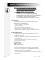
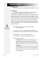
Section 1: Introduction/Description
Caution: This product is shipped from the factory set for
110-120 VAC operation. For 220-240 VAC operation,
settings must be changed before powering up.
See power settings below for 220-240 VAC.
Power Settings:
AC Power can be set for 110/120VAC OR 220/240VAC
via jumpers @ JP1 on Power PCB# 15759 or 21514, confirm setting.
For 220/240VAC = Jumper only center positions “B”
For 110/120VAC = Jumper both end positions “A” and “C”
A. Description:
The 2300 Series instrument is an all purpose analog weight
indicator with the following features:
• 6 digit, 7 segment .56" LED display
• Full numeric keypad
• LED indicators for modes and functions
• Outputs, and two (2) inputs for external switches
• Choice of AC only or Battery & AC power (when ordering only)
B. Model Differences:
• Original model units did NOT have an ON/OFF switch on the
keypad and are AC only.
• Neither their software nor their hardware allow battery operation
or battery add-on.
• Parts from an original may NOT be used in a new style
instrument and visa-versa.
( Original Styles )
15744 - Composite
15849 - Stainless Steel
• Newer models HAVE the new style keypad with an ON/OFF
switch, and are ordered WITH or WITHOUT battery option. All
contain the "bAtt' menu in their software.
Parts from an original may NOT be used in a new style instrument
and visa-versa.
50202
5
2/04
Issue #4
( Newer Styles)
22258 - AC Only Stainless Steel
21877 - AC Only Composite
21879 - AC/Battery Composite
22260 - AC/Battery Stainless Steel
The 2300 Series is available in an ABS hostile environment version
and in a hostile environment SS enclosure. The enclosure(s) come
with a mounting bracket suitable for desk or wall mount.
Options are Time Clock and 4-20mA output accessories.
C. Intended Applications:
Include, but are not limited to:
• Tank weighing assemblies
• Floor scales
• Bench scales
• Hopper scales
• Truck scales
50202
6
2/04
Issue #4
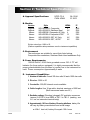
Section 2: Technical Specifications
A. Approval Specifications:
B. Models:
Version
Original:
Original:
Newer:
Newer:
Newer:
Newer:
NTEP CC #
CWM APAM
98-131A1
97-0103
Style
NEMA
IND-HR2300-1 Composite
4
IND-HR2300-2 Stainless Steel
4X
IND-HR2300-3 Composite, AC Only 4
IND-HR2300-4 Composite AC/DC
12
IND-HR2300-5 SST ,AC Only
4X
IND-HR2300-6 SST , AC/DC
4X
IP
IP66
IP66
IP66
IP40
IP66
IP66
Division sizes from .0002 to 50
(Platform capabilities take precedence over the instrument capabilities)
C. Environment:
The enclosures are suitable for use at their listed ratings.
Composite=Non washdown, Stainless Steel=Hand washdown Only
D. Power Requirements:
120/240 Volt AC, 50-60 Hertz grounded source -OR-- 6 "D" cell
batteries (for those units so equipped). It is highly recommended that the
proper grounds/shields from the base or junction box to the instrument be
used. Power consumption: Approximately 4 watts
E. Instrument Capabilities:
1. Number of load cells: 8 each 350 ohm cells/16 each 1000 ohm cells
2. Div size: .0002 to 50
3. Counts/div: 500,000 internal counts available
4. Cable lengths: Use 18 ga cable, absolute maximum of 500 feet.
(Must use sense leads over 25')
5. Excitation voltage: Pulsating (chopped) DC excitation measures
(approx) 5.00 DCV (true RMS) at TB1-1 to TB1-2 (reading - exc
to + exc on instrument terminal strip)
6. Approximately 100 hrs of battery life using alkalines, battery life
will vary by battery manufacturer and actual usage.
a. With 1 load cell, battery life equals 100+ hours
50202
7
2/04
Issue #4
Section 3: Setup
A. Unpacking:
Be certain the instrument is undamaged and the packing list is correct.
B. Installing:
Setup is accomplished by locating and securing the instrument
within a suitable area, wiring to the load cell(s) or junction box,
programming to meet specific needs, calibration, then adding peripheral
equipment as required. Place the instrument so that the platform can be
viewed while operating, out of direct sun, and close to a power outlet if AC
power is to be used. Configuration, calibration, accessory installation and
peripheral device setup must be performed by an authorized installing
technician. The instrument stand is attached via the two (2) screw knobs
and used as a desk mount, or a wall mount using the pre-drilled holes in
the base of the stand.
Note: When adjusting screw knobs, hand tighten only,
do NOT overtighten.
1. AC Power can be set for 110/120VAC OR 220/240VAC via
jumpers @ JP1 on Power PCB# 15759 or 21514, confirm setting.
For 220/240VAC = Jumper only center position "B"
For 110/120VAC = Jumper both end positions "A" and "C"
2. Models with battery option:
a. Stainless Steel: Open the battery holder's cover by
loosening the four thumbscrews and insert 6 NEW "D"
(alkaline) cells into the holder observing polarity. Ensure all
batteries are inserted correctly, then secure screws before
powering up.
b. Composite: Remove the battery holder cover and insert 6
NEW "D" (alkaline) cells into the holder observing polarity.
Ensure all batteries are inserted correctly, then secure cover
before powering up.
50202
8
2/04
Issue #4
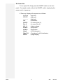
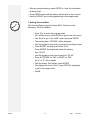
C. Power On:
To turn power ON, firmly press the ON/OFF switch on the front
panel. On original models, without the ON/OFF switch, simply plug the
power cord in to power up.
A 'Power-up' display will sequence is as follows:
LL.LLLL
(digit test)
777.777
(digit test)
- - - -. - (digit test)
init.
(initialization
P21579
(or current Prom # )
Rev 2
(or current Rev #)
X.X U
(battery voltage)
XX.XCs
(temperature
XX.XCn
(temperature
Adinit
(A-D Initialization)
Stby 25-1
(Countdown for A-D Initialization)
XXX.X
(weight display)
50202
9
2/04
Issue #4
Section 4: Programming
A. Keyboard Layout:
Description of front panel keys and their function(s):
Note: The original model's keypad does NOT have an
ON/OFF switch key.
Used the enter PROGRAM mode
Used to view choices in PROGRAM mode
Used to set ID or Identification number
Changes from GROSS to NET modes/ exits from Program mode.
Selects weighing Units
Captures weight on platform as TARE, sets display to 00
Resets display to 00
Reads current stored TARE weight
Sends data to printer device(s)
Transacts "keyed" data into memory
Number 0 to 9 for ID or Tare entries
& used in programming
Decimal for data entry in decimals
Press FIRMLY to turn power ON, then OFF
50202
10
2/04
Issue #4
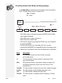
B. Getting Started with Menus and Programming:
1. The Main Menu is accessed from the weigh screen by pressing
PGR. The Main Menu's layout is shown here:
'Pgr' = Program
'S' = Scroll
5052
Weight
Display
S = scroll
Pgr
inFo
Main Menu Choices
S
io
S
CAnnEd
S
ConFiG
S
S
CAL
CALno0
• Each Main menu is accessed by pressing ENTER with the Main
menu legend displayed
• Each Main menu contains sub-menus
• Each sub-menu contains data
• Data can be viewed by pressing the SCROLL key, and 'accepted'
by pressing ENTER
• Pressing the SCROLL key repeatedly will exit to a menu
• Pressing the GROSS/NET key repeatedly will exit to the weigh screen
• Menus can be accessed in any order for adjustments or calibration
Menu
Info
io
BAtt
Description
NO password needed, set Time & Date, view data,
print config reports
"U" code required, set up all ports for printers,and other
devices and outputs
NO password needed, view battery voltage, set sleep time
and display brightness (Original instruments did NOT have
the bAtt menu)
CAnnEd
ConFig
CAL
CALno0
50202
"S" code
"S" code
"S" code
"S" code
scale
required,
required,
required,
required,
11
clears memory and sets a default program
set all weighing parameters here
calibrate zero and span
re-calibrate without emptying or zeroing
2/04
Issue #4
C. info Menu:
The info menu may be accessed without a code. This menu may be
looked at by Weights and Measures to check the "S Audt", "U Audt", or "C
Audt" for entries after a seal has been attached. This menu contains other
good information such as CoUntS for checking live counts, dEg C for
checking the ambient temperature of the instrument location, and CPg or
the counts per division. IF installed, time & date settings are accessed
here.
• Press 'Pgr' to enter the program mode
Weight
Display
S = Scroll
E
50523-7
= Enter
Pgr
Note: rEPort will show IF a printer is enabled in io.
E
Note: dAtE and HoUr will show IF Accessory for time and date is installed.
inFo
io
S
E
counts
(see note)
(see note)
S
dEg C
S
UAUdt
S
SAUdt
S
CAUdt
S
CPg
S
dAtE
S
HoUr
E
E
E
E
E
E
E
xxxxxx
xx.xC
XX
XX
XX
xx.xx
xxxxxx
xxxxxx
E
E
UdAtE
SdAtE
CdAtE
UcodE
UcodE
xxxxxx
xxxxxx
xxxxxx
xxxxxx
xxxxxx
hrdCPy
hrdCPy
hrdCPy
UdAtE
UdAtE
E
E
E
xxxxxx
xxxxxx
XXXXX
XXXXX
E
E
S
rePort
(see note)
E
• Press ENTER at the inFo menu
Prompts are:
Results are:
CoUntS
XXXXXX
dEg C
XX.X º C
U AUdt
User Audit
S AUdt
Service Audit
C AUdt
Calibration Audit
Cpg
Counts/Grad
dAtE
Date setting shows ONLY IF
Time/Date Accessory is installed
50202
hoUr
Time setting shows ONLY IF
Time/Date Accessory is installed
rEPort
Report
12
2/04
Issue #4
• With any prompt showing, press ENTER to 'view' the information
at that prompt.
• Press ENTER again and the display will advance to the io menu.
• Use the SCROLL key to exit programming to the weigh mode.
1. Setting Time and Date:
The time and Date prompts will show ONLY if the time clock
accessory 15819 is installed.
•
•
•
•
•
•
•
•
•
•
•
•
50202
Press 'Pgr' to enter the program mode
inFo will be shown, press ENTER to go into the inFo menu
Use 'Scroll' to go to the "dAtE" menu and press ENTER
The existing date, "XXXXXX" will be displayed
Use the keypad to enter the correct date in mmddyy format
Press ENTER, the display will show "hoUr"
Press ENTER, the display will show the existing
time "XX.XX"
Use the keypad to enter the correct time "XX.XX"
Press AUTOTARE for "AM" or PRINT for "PM",
an "A" or "P" will be added
With the proper Time shown, press ENTER
The display will show "rePort", press SCROLL repeatedly
to exit to the weigh mode
DONE
13
2/04
Issue #4
D. bAtt Menu: This menu is used for checking battery voltage, setting
'sleep' time, and display brightness. No passwords are required to
access this menu.
S
S
To access the BAtt menu:
• Press 'Pgr' to enter the program mode
• Use 'Scroll' to go to the BAtt menu
• Press ENTER
Prompts are:
XX.X U
Choices are:
The voltage reading of the installed batteries (U="V"olts)
NOTE: If AC power is used, the indication will NOT be accurate!
*SLEEP
SL 0
SLEEP
bright
Press ENTER or SCROLL to advance
The number of INACTIVE MINUTES before *'sleep' occurs
Press ENTER or SCROLL to advance
Enter 0=No sleep, 1-99 are active valid entries (use SCROLL)
Press SCROLL to advance
Hi, Lo (Use Lo to extend battery life by about 20%)
Press SCROLL
StorE
StorEd/CAnnEd Press GROSS/NET
Note: If either SLEEP or BRIGHT are accessed, the SCROLL key
will advance to STORE. If neither are accessed, then
SCROLL will 'loop' SLEEP-to-BRIGHT until an entry is made,
or, the Gross/Net key is pressed repeatedly to exit
programming and return to the weigh mode.
50202
14
2/04
Issue #4
* The 'sleep' option: If the scale is idle at "0" (zero) for the amount
of programmed 'sleep' time, the display will start to scroll
dashes (- - - - - -) from right to left and momentarily flash
"ASLEEP". It will stay this way for about 5 minutes if the
scale is undisturbed, then turn OFF. If the scale is used in
that 5 minute period, it will resume weighing, and reset the
'sleep' timer. The ON/OFF switch must be pressed to
repower the unit if it turns itself OFF.
50202
15
2/04
Issue #4
Section 5: Operation
A. Keyboard features:
Include eight (8) LED indicators that "light" when that function or
parameter is selected.
ID
PROGRAM
lb
kg
oz
g
*lb & oz
TARE
NET
Indicates the instrument is in the ID entry mode.
Indicates the instrument is in the program mode
Indicates pounds (lb) is selected as the weighing unit
Indicates kilograms (kg) is selected as the weighing unit
Indicates ounces (oz) is selected as the weighing unit
Indicates grams (g) is selected as the weighing unit
Indicates pound-ounces (lb-oz) is selected as the weighing unit
Indicates the inst. is in the TARE mode, displays TARE weight
Indicates the inst. is in the NET mode, displays NET weight
* The lb-oz unit is NOT LEGAL for TRADE, do NOT use in
commercial applications.
Notes: If neither TARE or NET are selected,
the instrument is in GROSS mode.
B. Other Key Functions:
1. Using ID
Press ID, then press numeric keys 0-9 (up to six [6] digits) for
unique customer or container number.
Example:
Press ID, 55147, then press ENTER, 55147 is temporarily stored as ID.
ID can then be printed on a ticket to identify a weighment.
ID is not saved through power reset.
2. Using TARE
Enter numeric value in proper units, then press ENTER. Value
becomes a stored TARE weight. Enter 0, then ENTER to set a
"zero" tare. Press TARE to view temporary TARE weight. Tare is not
saved through power reset.
50202
16
2/04
Issue #4
3. Using UNITS
IF 2 or more UNITS are set up in programming, then pressing the
UNITS key will toggle through all choices. Selecting units will show
another division size, and possibly different decimal places. Units
reset to primary unit on power reset.
C. Weighing Operation
1. Gross Weighing
a. Use ZERO key to set scale to 0.0
b. Place container/vehicle on scale
c. If ID is desired, Press ID, enter numeric ID, press ENTER
d. Record/Read GROSS weight
2. Net Weighing
a. Use ZERO key to set scale to 0.0
b. Place container/vehicle on scale (Tare weight)
c. Press AUTOTARE or enter TARE weight via keypad
d. Place material in container/vehicle (net weight)
e. If ID is desired, Press ID, enter numeric ID, press ENTER
f. Record/Read NET weight
3. Gross/Tare/Net Weighing
a. Use ZERO key to set scale to 0.0
b. Place container/vehicle on scale (Tare weight)
c. Press AUTOTARE or enter TARE weight via keypad
d. Place material in container/vehicle (Net weight)
e. Press Gross/Net
f. If ID is desired, Press ID, enter numeric ID, press ENTER
g. Record/Read Gross/Tare/Net Weight
50202
17
2/04
Issue #4
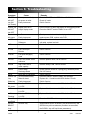
Section 6: Troubleshooting
Symptom
ON/OFF sw
will NOT
turn ON
(AC Power)
ON/OFF sw
will NOT
turn OFF
Blank with
AC power
no rEF
Cause
Sw not pressed firmly
No power at outlet
Faulty Instrument
Remedy
Press the ON/OFF switch FIRMLY and SLOWLY to turn ON
Check AC outlet
Call for Service
Display must be in
Press SCROLL to return the display to the weighing mode
weight display mode
Press the ON/OFF switch FIRMLY to turn OFF
No Power
Check power, check outlet, check plug, check cord,
Faulty Instrument
replace power PCB, replace main PCB
No Load Cell
Connect simulator to test, attach load cell, replace load
Reference
cell cable, replace load cell
InPErr
Input Error
Call for Service
Lo CPd
Low Counts per
Call for Service
Division
LoSPAn
Low Span Weight(s)
Call for Service
Used
LoLoAd
Low Load, below ZERO
Remove platform bind, Call for Service
reference
HiLoAd
High Load, above
Remove Heavy Load, Call for Service
scale capacity
ESdrSt
Electro Static
Check grounds, check for 3 prong plug, reinitialize power,
Discharge Reset
Call for Service
gt6chr
More than 6 Characters
Call for Service
ON/OFF sw
Sw not pressed firmly
Press the ON/OFF switch FIRMLY and SLOWLY
Inop
Batteries dead
Replace ALL 6 batteries with NEW alkaline "D"cells
(Batteries)
Faulty Instrument
Call for Service
Blank
Batteries BELOW
Replace ALL 6 batteries with NEW alkaline "D"cells
DC power
6.4 VDC
LoBAtt
Batteries at about
Replace ALL 6 batteries with NEW alkaline "D"cells
6.4 VDC
LoBAtt
Batteries BELOW
Replace ALL 6 batteries with NEW alkaline "D"cells
'Flashing'
6.4 VDC
Was ON
Sleep 'timed out'
Press the ON/OFF switch to repower unit
SCROLL key
Access either SLEEP or BRIGHT via the ENTER key, the
now Blank
SLEEP/
BRIGHT
SCROLL key will now advance.(If neither are accessed,
'loop'
the SCROLL key will 'loop' these parameters).
50202
18
2/04
Issue #4
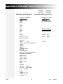
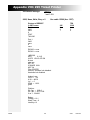
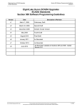
Appendix I: PTR-3950 Ticket Printer Information
PTR-3950 Switch Settings:
2400, None, 8 Bits, Busy=0
SW1
SW2
12345678
12345678
01100011
10010010
Use Cable 15598 ( Acc 1296 )
Printout of REPORT
in INFO menu
Port 2:
2400
none
8
CRLF
3950
Printout of U Audt
in INFO menu
User Audit
57
Audit Date 092898
Port 1:
2400
none
8
Frbnks
Printout of Ticket
1670 lb GROSS
EXSW2 = >0<
EXSW1 = PRINT
1ND2300:
d/PU
1 LB
UNITS LB KG OZ GM LB-OZ
kb tare
auto tare
AZT ld
0 RANGE 100%
MOT 1d
Filter MEDIUM
Security: Software lock disabled
Hardware lock disabled
1000 lb
NET
670 lb
TARE
125 ID
Analog Loop:
Lo W = 00
Hi W = 18500
Lo I = 0
SPAN = 102
gross
Platform:
PU Cap = 1000
PU Cpd = 637.508000
0 ref = 348458
Battery:
Voltage = 27.3
Sleep Time = 0
Intensity = Lo
50202
19
2/04
Issue #4
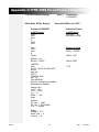
Appendix II: PTR-3960 Form Printer Information
PTR-3960 Switch Settings:
9600, None, 8 Bits, Busy=0
SW1 =
12345678910
1110000000
Use cable15599 ( Acc 1297 )
Printout of REPORT
in INFO menu
Printout of Uaudt
in INFO menu
Port 2:
9600
none
8
CRLF
3960
User Audit
33
Audit Date 092898
Port 1:
2400
none
8
Frbnks
Printout of Ticket
2500 lb GROSS
1000 lb NET
EXSW2 = >0<
EXSW1 = PRINT
1500 lb TARE
1ND2300:
d/PU
1
UNITS LB KG OZ GM LB-OZ
kb tare
auto tare
AZT ld
0 RANGE 100%
MOT 1d
Filter MEDIUM
Security: Software lock disabled
Hardware lock disabled
77 ID
Analog Loop:
Lo W = 00
Hi W = 18500
Lo I = 0
SPAN = 102
gross
Platform:
PU Cap = 1000
PU Cpd = 637.508000
0 ref = 348458
Battery:
Voltage = 27.3
Sleep Time = 0
Intensity = Lo
50202
20
2/04
Issue #4
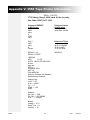
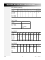
Appendix III: 50-3921 Form Printer Information
50-3921 Form Printer Switch Settings:
SW1(super spd ser bd)
SW2 (super spd ser bd)
12345678
12345678
11111111
01100110
9600, None, 8 Bits, Busy=0
DipSW (Main PC)
12345678
00001010
Use cable 15599 ( Acc 1297 )
Printout of REPORT
in INFO menu
Port 2:
9600
none
8
CRLF
3921
Printout of Uaudt
in INFO menu
User Audit
16
Audit Date 092898
Port 1:
2400
none
8
Frbnks
Printout of Ticket
30.00 oz GROSS
12.50 oz NET
17.50 oz TARE
EXSW2 = >0<
EXSW1 = PRINT
4077 ID
1ND2300:
d/PU
.01 OZ
UNITS LB KG OZ GM LB-OZ
kb tare
auto tare
AZT ld
0 RANGE 100%
MOT 1d
Filter MEDIUM
Security: Software lock disabled
Hardware lock disabled
Analog Loop:
Lo W = 00
Hi W = 18500
Lo I = 0
SPAN = 102
gross
Platform:
PU Cap = 1000
PU Cpd = 637.508000
0 ref = 348458
Battery:
Voltage = 27.3
Sleep Time = 0
Intensity = Lo
50202
21
2/04
Issue #4
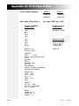
Appendix IV: 610 Ticket Printer Information
610 Switch Settings:
Switch 1
12345678
01001011
1200, Odd, 7 Bits, Busy=1
Use cable 15598 (Acc 1296 )
Printout of REPORT
in INFO menu
Port 2:
9600
none
8
CRLF
3921
Printout of Uaudt
in INFO menu
User Audit
11
Audit Date 101098
Port 1:
2400
none
8
Frbnks
Printout of Ticket
EXSW2 = >0<
EXSW1 = PRINT
555555 ID
30.00 oz GROSS
12.50 oz NET
17.50 oz TARE
1ND2300:
d/PU
.01 OZ
UNITS LB KG OZ GM LB-OZ
kb tare
auto tare
AZT ld
0 RANGE 100%
MOT 1d
Filter MEDIUM
Security: Software lock disabled
Hardware lock disabled
Analog Loop:
Lo W = 00
Hi W = 18500
Lo I = 0
SPAN = 102
gross
Platform:
PU Cap = 1000
PU Cpd = 637.508000
0 ref = 348458
Battery:
Voltage = 27.3
Sleep Time = 0
Intensity = Lo
50202
22
2/04
Issue #4
Appendix V: 3550 Tape Printer Infromation
SW1 = 0111010100
SW2 = 11111010
3715 Setting, Busy 0, 4800 baud, 8 bits, no parity
Use Cable 15597 (ACC 1295)
3550 Switch Settings:
Printout of REPORT
in INFO menu
Port 2:
9600
none
8
CRLF
3921
Printout of Uaudt
in INFO menu
User Audit
11
Audit Date 101098
Port 1:
2400
none
8
Frbnks
Printout of Ticket
30.00 oz GROSS
12.50 oz NET
17.50 oz TARE
EXSW2 = >0<
EXSW1 = PRINT
555555 ID
1ND2300:
d/PU
.01 OZ
UNITS LB KG OZ GM LB-OZ
kb tare
auto tare
AZT ld
0 RANGE 100%
MOT 1d
Filter MEDIUM
Security: Software lock disabled
Hardware lock disabled
Analog Loop:
Lo W = 00
Hi W = 18500
Lo I = 0
SPAN = 102
gross
Platform:
PU Cap = 1000
PU Cpd = 637.508000
0 ref
= 348458
Battery:
Voltage = 27.3
Sleep Time = 0
Intensity = Lo
50202
23
2/04
Issue #4
Appendix VI: 3715 Tape Printer
50-3715 Switch Settings:
Switch 1
12345678
00000100
Switch 2
12345678
01001010
2400, None, 8 Bits, Busy =1
Use cable 15597 (Acc 1295)
Printout of REPORT
in INFO menu
Port 2:
9600
none
8
CRLF
3921
Printout of Uaudt
in INFO menu
User Audit
11
Audit Date 101098
Port 1:
2400
none
8
Frbnks
Printout of Ticket
EXSW2 = >0<
EXSW1 = PRINT
555555 ID
30.00 oz GROSS
12.50 oz NET
17.50 oz TARE
1ND2300:
d/PU
.01 OZ
UNITS LB KG OZ GM LB-OZ
kb tare
auto tare
AZT ld
0 RANGE 100%
MOT 1d
Filter MEDIUM
Security: Software lock disabled
Hardware lock disabled
Analog Loop:
Lo W = 00
Hi W = 18500
Lo I = 0
SPAN = 102
gross
Platform:
PU Cap = 1000
PU Cpd = 637.508000
0 ref = 348458
Battery:
Voltage = 27.3
Sleep Time = 0
Intensity = Lo
50202
24
2/04
Issue #4
Appendix VII: 590 Ticket Printer
590 Switch Settings:
Switch 1
1,3,7 ON
9600, None, 8bits, Busy = 1
Switch 2
All Off
Use cable 15598 (Acc 1296)
Printout of REPORT
in INFO menu
Port 2:
9600
none
8
CRLF
TM-U590
590
3
4
7
TB2
2300
2
3
4
Port 1:
2400
none
8
none
EXSW2 = none
EXSW1 = none
1ND2300:
d/PU
.01 LB
UNITS LB KG OZ GM
kb tare
auto tare
AZT 3d
0 RANGE 100%
MOT 3d
Filter CENTER
Security: Software lock disabled
Hardware lock disabled
Analog Loop:
Lo W = 6.6
Hi W = 800.0
Lo I = 0
SPAN = 103.2
gross
Platform:
PU Cap = 1000.0
PU Cpd = 26.217100
0 ref = 524250
Battery:
Voltage = 16.1
50202
25
2/04
Issue #4
Appendix VIII: 295 Ticket Printer
Switch 1
295 Switch Settings:
1 and 3 ON
9600, None, 8bits, Busy = 0
Use cable 15599 (Acc 1297)
Printout of REPORT
in INFO menu
Port 2:
9600
none
8
CRLF
TM-U295
295
2
3
7
TB2
2300
1
2
4
Port 1:
2400
none
8
none
EXSW2 = none
EXSW1 = none
1ND2300:
d/PU
0.1 LB
UNITS LB KG OZ GM
kb tare
auto tare
AZT 3d
0 RANGE 100%
MOT 3d
Filter CENTER
Security: Software lock disabled
Hardware lock disabled
Analog Loop:
Lo W = 6.6
Hi W = 800.0
Lo I = 0
SPAN = 103.2
gross
Platform:
PU Cap = 1000.0
PU Cpd = 26.217100
0 ref = 524250
Battery:
Voltage = 16.1
Sleep Time = 0
Intensity= Hi
50202
26
2/04
Issue #4
Appendix IX: Interface Cables/Pin-Outs
Port 1 RS232 (continuous)
From TB4 in the
3715
indicator
25Pin
Pin 1 TX RS232
Pin 2 GND
Pin 3 +5V
Pin 4 +20mA
3950
25Pin
3921
25Pin
3960
25Pin
Computer
25 Pin
3
7
Computer RMT140XA
9 Pin (using RS232)
2
3
5
2
Pin 5 -20mA
Port 1 20mA
From TB4 in the
indicator
Pin 4 +20mA
Pin 5 -20mA
RMT 140XA/150X
1
5
2
6
jumper
Port 2 RS232
From TB2 in the
indicator
Pin 1 RX
Pin 2 TX
Pin 3 CTS
Pin 4 GND
Pin 5 RTS
Cable Acc
3715
25Pin
3550
25 Pin
3
20
7
15597
3950
25 Pin
3
20
7
3
4
7
15597
3921
25 Pin
2
3
3960
25 Pin
2
3
7
7
15598
Comp
25 Pin
2
3
7
15598 15599
Comp
9 Pin
3
2
5
TMU
590
3
4
7
TMU
295
2
3
7
15599
Port 2 RS485
From TB3 in the
indicator
Pin 1 485+
Pin 2 485Pin 3 GND
Pin 4
3715
25 Pin
3950
25 Pin
3921
25 Pin
3960
25 Pin
Comp
25 Pin
RX+
RX-
Comp
9 Pin
RX+
RX-
Pin 5
50202
RMT
140XA
_
_
_
_
_
27
2/04
Issue #4
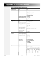
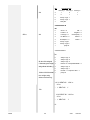
Appendix X: Port 1 Data Stream
Port 1 Continuous Output Data Stream:
Selected Format
Fairbanks Std
Weightronix
Consolidated
Controls
dPlus
50202
Char
1st
2nd
3rd
Assignment
Stx
‘4’
‘0’ gross lbs or ounces
‘1’ net lbs or ounces
‘3’ gross kgs or grams
‘4’ net kgs or grams
4th thru signed weight '- 12.33' or
string e.g. 9th or 10th ' 20' or
'- 1'
10th
Etx
1st
'0' if net ' ' if gross
2nd
'N' " " 'G' " "
3rd thru signed weight
string e.g. 8th or 9th
'-12.33' or
' 20' or
'- 1'
9th, 10th & 11th OR
10th, 11th, & 12th
'lb' or 'kg' or 'g' or 'oz' or 'lb-oz'
12th & 13th OR
13th & 14th
1st
2nd thru signed weight
string e.g. 7th or 8th
Cr and Lf
Stx
'-12.33' or
' 20' or
'- 1'
9th or 10th
10th or 11th
'L' or 'K' or 'G' or 'O'
'O' or 'I' indicator Error
'M' Motion
' ' No Motion
12th or 13th
1st
2nd
Cr
Sx
STATUS WORD A
Bit
Decimal point or Dummy Zero
28
x00 x0
x
x.x x.xx x.xxx x.xxxx x.xxxxx
0
1
1
0
0
1
0
1
0
1
1
0
0
1
1
0
0
1
2
1
0
0
0
0
1
1
1
2/04
Issue #4
Bit
Increment Size
Count by 1
3rd
Count by 2
Count by 5
1
0
1
4
0
1
1
5
Always Logic 1
6
Always Logic 1
7
Parity Bit
3
STATUS WORD B
Bit
dPlus
4th
0
Gross = 0
Net = 1
1
Positive = 0
2
In Range = 0
3
No Motion = 0
Motion = 1
4
Avoirdupois = 0
Metric = 1
5
Always Logic 1
6
Always Logic 0
7
parity bit
Negative = 1
Overcapacity = 1
STATUS WORD C
Bit
5th thru 10th unsigned
0
Always Logic 0
1
Always Logic 0
2
Always Logic 0
6 character gross weight 3
Normal = 0 Print Operated Switch = 1
string without decimal e.g. 4
Always Logic 0
5
Always Logic 1
6
Normal = 0 Keyboard Tare = 1
11th thru 16th 6 character 7
parity bit
tare weight string
without decimals e.g.
'-12.33' SENT AS ' 1233' or
'
'-
20' or
1' SENT AS ' 1'
17th
' 12.33' SENT AS ' 1233' or
'
'-
20' or
1' SENT AS '
1'
Cr
50202
29
2/04
Issue #4
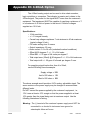
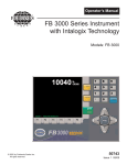
Appendix XI: 4-20mA Option
The 4-20mA analog output can be used to drive chart recorders,
logic controllers or computers. The indicator is passive as it relates to the
4-20mA signal. The power for the signal MUST come from the customer's
equipment. That equipment MUST be capable of supplying a minimum of 7
to a maximum of 40 volts of power to that circuit. Common voltages
supplied are 12-24 vdc.
Specifications:
• 16 bit resolution
• +/- .01 integral linearity
• Current loop voltage compliance: 7 vdc minimum to 40 vdc maximum
(typical voltage 24 vdc)
• Full scale settling time: 8 msecs
• Output impedance: 25 meg
• Alarm current: 3.5 to 24 mA (underload/overload conditions)
• Offset @ 25 degrees C; +/- .1% of full scale
• Offset drift: +/- 25 ppm of full scale per degree C
• Total output error: (20mA) @ 25 degrees C: +/- .2% of full scale max
• Total output drift: +/- 50 ppm of full scale per degree C max
For supplying signal levels other than 4 to 20mA,
use the following formula example:
Supply voltage = 12V
4mA x 500 ohms = 2V
20mA x 500 ohms = l0V
The above example would provide a 2-l0V analog, adjustable signal. The
sense resistor or the power supply may be changed to accommodate
different levels.
Do NOT exceed the power supplied by the customer's equipment, i.e.,
12V. Leave at least a 10% margin so that the power supplied is at least
10% greater than the signal being sent at maximum output. Use the
following illustrations for wiring.
Warning: The (-) terminal of the customer's power supply must NOT be
connected to or shorted to instrument case ground or
catastrophic failure will occur.
50202
30
2/04
Issue #4
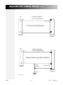
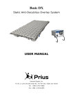
Appendix XII: 4-20mA Option
TB7
Continued
Customer Supplied
12-24 V Power Supply
(+)
1
4 to 20 mA Wiring Diagram
2
(-)
Customer's
Equipment
Main PCB
TB7
1
Customer Supplied
12-24 V Power Supply
(+)
Voltage Output using Sense Resistor
2
(-)
Sense
Resistor
Main PCB
Ground
Voltage Output
Customer's
Equipment
50523-16
50202
31
2/04
Issue #4
Appendix XIII: ASCII Chart
Decimal
Code #
0
1
2
3
4
5
6
7
8
9
10
11
12
13
14
15
16
17
18
19
20
21
22
23
24
25
26
27
28
29
30
31
32
Control
Char
NUL
SOH
STX
ETX
EOT
ENQ
ACK
BEL
BS
HT
LF
VT
FF
CR
S0
S1
DLE
DC1
DC2
DC3
DC4
NAK
SYN
ETB
CAN
EM
SUB
ESC
FS
GS
RS
US
Space
Decimal
Code #
33
34
35
36
37
38
39
40
41
42
43
44
45
46
47
48
49
50
51
52
53
54
55
56
57
58
59
60
61
62
63
64
65
Control
Char
!
"
#
$
%
&
'
(
)
*
+
,
_
.
/
0
1
2
3
4
5
6
7
8
9
:
;
<
=
>
?
@
A
Decimal
Code #
66
67
68
69
70
71
72
73
74
75
76
77
78
79
80
81
82
83
84
85
86
87
88
89
90
91
92
93
94
95
96
97
98
Control
Char
B
C
D
E
F
G
H
I
J
K
L
M
N
O
P
Q
R
S
T
U
V
W
X
Y
Z
[
\
]
^
`
a
b
Decimal
Code #
99
100
101
102
103
104
105
106
107
108
109
110
111
112
113
114
115
116
117
118
119
120
121
122
123
124
125
126
127
Control
Char
c
d
e
f
g
h
i
j
k
l
m
n
o
p
q
r
s
t
u
v
w
x
y
z
{
|
}
~
Delete
NOTE: Refer to your printer or computer's User Manual for special control
codes that your printer or computer may require for proper operation.
50202
32
2/04
Issue #4