1
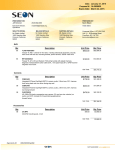
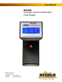
User Manual
AVI-CR
Automatic Vehicle Identification
Code Reader
Diablo Controls, Inc.
Copyright © 2015
Document:
AVI-CR_MAN_A
Released:
September 3, 2015
Pros Who Know Trust Diablo
1. Contents
Figures .................................................................................................................................................................... 2
2.
Introduction ........................................................................................................................................... 3
3.
Features and Functions ........................................................................................................................... 4
Multiple Code Reception ........................................................................................................................................ 4
Audible Buzzer ........................................................................................................................................................ 4
Battery Voltage Display .......................................................................................................................................... 4
Extendable Sensing Wand ...................................................................................................................................... 4
Use without Wand .................................................................................................................................................. 4
Splash Screen .......................................................................................................................................................... 4
Code Display Screen ............................................................................................................................................... 5
4.
Operation ............................................................................................................................................... 6
Battery Installation ................................................................................................................................................. 6
Connecting Display Unit to Wand .......................................................................................................................... 6
Extending the Sensing Wand .................................................................................................................................. 6
Rotating the Sensing Head on the Wand ............................................................................................................... 6
Adjusting the Angle of the Sensing Head on the Wand ......................................................................................... 6
Reading Codes ........................................................................................................................................................ 7
5.
Troubleshooting ..................................................................................................................................... 7
Nothing Happens When the Button is Pressed ...................................................................................................... 7
Weak Reception...................................................................................................................................................... 7
The Display is Hard to Read .................................................................................................................................... 7
Figures
Figure 1: AVI Code Reader as supplied .......................................................................................................................3
Figure 2: Code Display Screen ....................................................................................................................................5
Figure 3: Wand Extension Clamp................................................................................................................................6
AVI-CR User Manual
Page 2 of 7
AVI-CR_MAN_A
2. Introduction
An Automatic Vehicle Identification (AVI) system consists of an AVI transmitter, an optional AVI security device, a
sensing loop, and an AVI receiver. The transmitter and receiver must be configured to use the same AVI code.
Some transmitters are capable of transmitting more than one AVI code at a time or can change codes based on
the state of a switch. The optional security device can be used to ensure that a transmitter will not work if
removed from a vehicle (the transmitter and security device are permanently paired). The sensing loop is typically
a coil of wire embedded in the driving surface. The sensing loop can be used as an inductive vehicle detection
loop as well. Some receivers are capable of receiving more than one AVI code to activate its output.
The AVI-CR is a hand held unit used to verify the operation of AVI transmitters. Since most transmitters will already
be mounted on a vehicle, the code reader is supplied with a sensing wand. The sensing wand has an extendable
shaft that allows the unit to be compacted for storage. The handheld display unit can be used with or without the
sensing wand and is capable of receiving up to four codes at once from the same transmitter.
The AVI-CR is delivered as four items:
1.
2.
3.
4.
Display unit
Extendable Sensing wand
Coiled cord
9 volt battery
2
3
1
4
Figure 1: AVI Code Reader as supplied
AVI-CR User Manual
Page 3 of 7
AVI-CR_MAN_A
3. Features and Functions
Multiple Code Reception
The code reader capable of receiving up to four codes from a single transmitter. Each code must be sent a
minimum of three times in a row before changing to a different code. The display will indicate the number of
consecutive reads for each code being received.
Audible Buzzer
The code reader will generate two audible beeps every time a new code is received. If a transmitter is transmitting
two or more codes at the same time, the code reader will generate up to eight beeps (two for each code) when
the codes are first received.
Battery Voltage Display
The code reader will display the actual battery voltage of the 9 volt battery in the display unit. When the battery
voltage goes below six volts, a low battery message will be displayed in the battery voltage display area.
Extendable Sensing Wand
The code reader is provided with an extendable sensing wand. When extended, it allows the operator to easily
position the sensing coil under a vehicle to check an installed transmitter. The sensing coil can be retracted and
rotated 90 degrees for easy and compact storage.
Use without Wand
The display unit can be used without the sensing wand. When using just the display unit, get the unit with a foot
or two of an operating transmitter to read the code. The actual read distance is dependent on the orientation of
the display unit to the transmitter.
Splash Screen
When the power button is first pressed, a splash screen will be displayed for one second that will identify the
product and the firmware version.
AVI-CR User Manual
Page 4 of 7
AVI-CR_MAN_A
Code Display Screen
The code display screen is composed of several pieces of information:
1
5
2
6
3
7
4
8
9
10
Figure 2: Code Display Screen
1. First Code Read – The first code that was received by the code reader. If no codes are being received,
this value will be zero.
2. Second Code Read – The second code that was received by the code reader. If a second code is not
being received, this value will be zero.
3. Third Code Read – The third code that was received by the code reader. If a third code is not being
received, this value will be zero.
4. Fourth Code Read – The fourth code that was received by the code reader. If a fourth code is not being
received, this value will be zero.
5. Number of Consecutive Receptions of the First Code – The number of times that the first code was
received in a row before the code being received changed. If only one code is being received, this count
will always be 50. If no codes are being received, this count will be zero.
6. Number of Consecutive Receptions of the Second Code – The number of times that the second code
was received in a row before the code being received changed. If a second code is not being received,
this count will be zero.
7. Number of Consecutive Receptions of the Third Code – The number of times that the third code was
received in a row before the code being received changed. If a third code is not being received, this
count will be zero.
8. Number of Consecutive Receptions of the Fourth Code – The number of times that the fourth code was
received in a row before the code being received changed. If a fourth code is not being received, this
count will be zero.
9. Total number of reads performed – The total number of reads that the reader has tried to make. This
count include time outs where no code was received.
10. Battery voltage – This is the real-time display of the 9 volt battery voltage. A low battery message will
displayed in this area when the battery voltage drops below six volts.
AVI-CR User Manual
Page 5 of 7
AVI-CR_MAN_A
4.
Operation
Battery Installation
The 9 volt battery needs to be installed in the display unit. Place the display unit face down and open the battery
compartment at the bottom by pressing the retaining clip towards the middle of the display unit and lifting up.
Install the 9 volt battery with the small post (the positive post) towards the bottom of the unit (as marked inside
the unit). Place the base of the battery in first then press the top of the battery in to place. Replace the battery
cover and snap it closed.
Connecting Display Unit to Wand
Connect one end of the coiled cord into the modular jack at the top of the display unit. Connect the other end in
to the modular jack on the side of the extendable sensing wand. The coiled cord is a standard telephone handset
cord. So the operator can easily acquire and use a shorter or longer cord as it suits their purpose.
Extending the Sensing Wand
The sensing wand has a clamp on the shaft that is used to lock the extension in to place. To adjust the extension,
pull up on the clamp handle. Adjust the extension to the desired length and press the clamp back down to lock
the extension in place.
Figure 3: Wand Extension Clamp
Rotating the Sensing Head on the Wand
The sensing head on the wand can be rotated for storage. The head only rotates 90 degrees. If it does not easily
rotate in one direction, try the other direction.
Adjusting the Angle of the Sensing Head on the Wand
The angle of sensing head on the wand can be adjusted for better reception sensitivity. To adjust the angle, loosen
the gray plastic finger nut where the sensing head attaches to the wand. Adjust the sensing head angle to be
parallel to the transmitter to be read then retighten the finger nut.
AVI-CR User Manual
Page 6 of 7
AVI-CR_MAN_A
Reading Codes
To read codes, depress the red button on the front of the display unit. The splash screen will be displayed for one
second and then the code display screen will be displayed. Now place the sensing coil on the end of the wand
near the transmitter to be read. If not using the wand, place the display unit near the transmitter (within two
feet). If the transmitter is powered up and functioning correctly, the code(s) that it is being transmitted will be
shown on the display unit and the unit will beep to announce that a new code has been read.
5. Troubleshooting
Nothing Happens When the Button is Pressed
Check the battery voltage with a meter if possible. If not possible, replace the battery with a known good
battery to insure that the battery is not the problem.
If the battery is good, open the display unit by removing all six screws from the back of the unit. Carefully open
the unit to not stress any of the cables between the two case halves. There should be a jumper across two pins
on a small printed circuit board on the back of the display. If it is missing, install a new jumper (it should be
inside the case somewhere if it came off). If it is installed, remove it and reinstall it. Reassemble the unit,
making sure not to pinch any cables between the two case halves. Press the power button. If the unit does not
operate normally, return it to Diablo Controls for service.
Weak Reception
Make sure that the sensing coil on the wand is orientated to be parallel to the transmitter being read. The code
reader should be able to read codes from one foot away or more.
Make sure that the transmitter being tested is actually working correctly. Check the reception strength with a
known good transmitter.
If the unit does not operate normally, return it to Diablo Controls for service.
The Display is Hard to Read
If the battery is good, open the display unit by removing all six screws from the back of the unit. Carefully open
the unit to not stress any of the cables between the two case halves. There will be a screen contrast adjustment
on a small printed circuit board on the back of the display. Using a small screw driver while pressing the power
button, adjust the contrast for best results.
AVI-CR User Manual
Page 7 of 7
AVI-CR_MAN_A