1
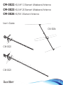
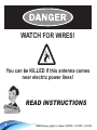
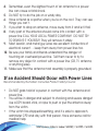
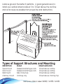
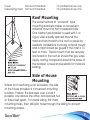
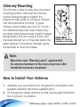
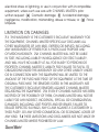
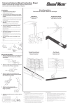
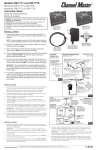
CM-3022
CM-3023
CM-3026
USER GUIDE
Table of Contents
Warning and Safety Information....................................................................2
Product Overview...................................................................................................................3
Package Contents and Accessories.............................................................3
Danger Information............................................................................................................4
- Warning.................................................................................................................................................5
- Follow These Procedures for the Safest Installation..............................5
- If an Accident Should Occur with Power Lines........................................6
- Important Guidelines for Installing Antennas...............................................7
- Site Selection: Where to Install Your Antenna.............................................7
- Types of Support Structures and Mounting....................................................8
• Roof Mounting...........................................................................................................................9
• Side of House Mounting..................................................................................................9
• Chimney Mounting........................................................................................................... 10
- How to Install Your Antenna....................................................................................... 10
- Antenna Removal.................................................................................................................. 12
- Lightning Protection............................................................................................................. 12
Installation Instructions......................................................................................... 13
Features and Benefits.................................................................................................. 19
Product Return Policy and Warranty.................................................... 21
CM-3022 HD/UHF 12 Element Wideband Antenna
CM-3023 HD/UHF 20 Element Wideband Antenna
CM-3026 HD/FM 3 Element Antenna
User’s Guide
CM-3026
CM-3022
CM-3023
1
Warning and Safety Information
Please read this user’s manual before operating this product.
The information contained in this document is subject to change without
notice. Features or specifications may be different depending on the type of
product model purchased.
Safe Use of This Product
Carefully follow the warnings and safety notices presented within this
manual. Please pay special attention to the following indications of
potentially hazardous situations:
Warning:
Indicates a hazardous situation, which, if not avoided, could result in
serious injury.
Caution:
Indicates a situation, which, if not avoided, could damage this product or
other devices.
Note:
Indicates additional user information to make the user aware of possible
problems and to help the user understand, use and maintain the product.
2
Product Overview
All Channel Master - Masterpiece Antennas are future-proof and
legacy protected. So you can have the confidence that no matter
what the installation requirement, you have it all covered in one
quality antenna.
Because time is money, all Masterpiece Antennas are engineered to
be easy to install. Simply open the box, click open and you’re ready
to go! We know how important time is to the installer. The entire
Channel Master Masterpiece Antenna is engineered so that every bit
just ‘clicks’ into place, U-bolts are fitted on most models.
No fiddling, dropping or scratching around - it’s all there on the
antenna ready to go. This attention to detail is also seen in the
antenna ends and edges; every piece is crimped and machined to
ensure a safe, trouble-free installation. Every antenna is made of the
finest components to exceed even the most extreme conditions.
That means peace of mind for you for years to come.
Package Contents and Accessories
Thank you for purchasing the Channel Master CM-3022, CM-3023 or
CM-3026 Antenna.
CM-3022 Antenna, User Guide
CM-3023 Antenna, User Guide
CM-3026 Antenna, User Guide
3
WATCH FOR WIRES!
You can be KILLED if this antenna comes
near electric power lines!
READ INSTRUCTIONS
4
Warning
Installation of this product near power lines is dangerous. For your
safety, follow the installation directions.
Before you start installation, let us warn you of the danger of letting
any part of your antenna system touch electrical power lines - you may be killed.
It happens more often than you realize! Someone falls off of a roof or
gets the shock of their life.
Unfortunately, a good antenna site is often near electrical power lines.
If any metal antenna part touches a power line, it completes an
electrical path through the installer (that’s you!) to the ground.
Follow These Procedures for the
Safest Installation
1. Perform as much antenna assembly on the ground as possible.
2. Watch out for overhead power lines. Check the distance to the
power lines before you start installing. WE RECOMMEND YOU STAY
A MINIMUM OF TWICE THE MAXIMUM LENGTH OF THE ANTENNA
ASSEMBLY AWAY FROM ALL POWER LINES.
3. Do not use a metal ladder.
5
4. Remember, even the slightest touch of an antenna to a power
line can cause a fatal shock.
5. Do NOT try to do the job on a windy day.
6. Have a friend as a spotter when you’re on the roof. They can see
things you can’t.
7. If you start to drop an antenna, move away from it and let it fall.
8. If any part of the antenna should come into contact with a
power line CALL YOUR LOCAL POWER COMPANY! DO NOT TRY
TO REMOVE IT YOURSELF! They will remove it safely.
9. Mast, lead-in, and metal guy wires are excellent conductors of
electrical current - - keep them away from power lines too.
10. Be sure your family and friends understand the danger of
touching an overhead power line. Tell them never to try to
remove any object in contact with a power line (CB, TV antenna,
or anything else).
11. Make sure that the antenna mast assembly is properly grounded.
If an Accident Should Occur with Power Lines
Recommended by the Nation Consumer Product Safety Council.
•
•
•
6
Do NOT grab hold of a person in contact with the antenna and
power line.
You will be in danger and subject to shocking and severe danger!
Use a DRY board, stick, or rope to push or pull the antenna away
from the victim.
If the victim has stopped breathing, and it is safe to approach,
administer CPR and stay with that person. Have someone call for
medical help.
Important Guidelines for Installing Antennas
If you’re not sure about careful, safe installation – do NOT try to do it
yourself. Call for professional help (look up Television Antenna Systems
in your area or call your local power company).
Measure the maximum length of the antenna and mast assembly and
then stay at least twice that distance away from power lines.
(If you don’t have at least this much space, hire a professional to do
the installation.)
When using a mast for support, use only 1¼ inch diameter or larger
antenna mast sections. Lengths over 10 feet should be guyed at least
each 10 foot section.
Site Selection: Where to Install Your Antenna
Before attempting to install your antenna, think where you can best
place your antenna for safety and performance.
To
•
•
•
•
determine a safe distance from wires, power lines, and trees:
Measure the height of your antenna.
Add the antenna length to the length of your tower or mast.
Double this total for the minimum recommended safe distance.
If you are unable to maintain this safe distance, STOP!
GET PROFESSIONAL HELP.
Most antennas are supported by pipe masts attached to the
chimney, roof, or side of the house. Normally, the higher the antenna
7
is above ground, the better it performs. A good general rule is to
install your vertical antenna about 5 to 10 feet above the roof line
and as far away as possible from power line and obstructions.
Types of Support Structures and Mounting
DESCRIPTION
Tripod mount
Roof mount
Wall mount
Chimney mount
8
USAGE
Peaked and flat type roofs
Peaked and flat type roofs
Side of structure
Chimney only
HEIGHT LIMITATION
10 feet above rooftop
10 feet above rooftop
10 feet above rooftop
10 feet above chimney top
Tower
Not recommended.
Telescoping mast Not recommended.
For professional use only
For professional use only
Roof Mounting
The swivel feature of “universal” type
mounting brackets makes a convenient
antenna mount for flat or peaked roofs.
One clamp type bracket is used with 3 or
4 guy wires equally spaced around the
mast and anchored to the roof or eaves by
eyebolts. Installations involving a tripod mount
and a mast should be guyed if the mast is 10
feet or more. Tripod mount must be securely
anchored to the roof as should the guy wires.
Apply roofing compound around the base of
the bracket, screws and eyebolts for moisture
sealing.
Side of House
Mounting
Where roof overhang is not excessive, the side
of the house provides a convenient mounting
location. Position the brackets over a stud if
possible, one above the other, and spaced two
or three feet apart. For metal siding, first mark
mounting holes, then drill pilot holes through the siding to accept
mounting screws.
9
Chimney Mounting
The chimney is often an easy and convenient
mounting location. Note that the chimney
must be strong enough to support the
antenna in high winds. Do not use a chimney
that has loose bricks or mortar. A good
chimney mount makes use of a 5 or 10 foot ¼
inch diameter steel mast, and a heavy-duty
two strap clamp-type bracket. Install the upper
bracket below the top course of bricks, and
the lower bracket two or three feet below the
upper bracket. For maximum strength, space
the brackets as much as possible.
Note:
Mount the extra “Warning Label” supplied with
the antenna hardware to the mast at eye level after
installation has been completed.
How to Install Your Antenna
1. Assemble your new antenna on the ground in accordance with
separate assembly instructions supplied with it.
2. On the ground, clamp antenna to mast, pull enough transmission
line to connect to antenna.
10
3. Install selected mounting bracket.
4. If you are going to use guy wire installation instead of a mounting
bracket:
a. Install-guy anchor bolts
b. Estimate length of guy wire and cut
c. Attach to mast using guy ring
5. Mount the extra included “Warning Label” supplied in the
hardware bag on the antenna mast at eye level after installation
has been completed.
11
Antenna Removal
Removal of the antenna should be exactly the reverse of the
installation instructions. Please, for your own safety, follow the
instructions for installing the antenna starting with the last step first.
This is the safest method.
Lightning Protection
To protect your house and your TV (FM, CB, etc.) installation, the mast
of your antenna system must be properly grounded.
Antenna masts must be grounded to the same ground used for the
building’s electrical system. This will ensure that all exposed metal
parts are at the same electrical potential. The recommended
method is to run a #10 AWG or larger copper wire in as straight a line
as possible to the building grounding electrode system and must be
connected to the building ground using a UL listed ground clamp.
Also, an antenna discharge unit (sometimes referred to as a lightning
arrester) should be connected to the antenna lead-in at the place
where it enters the home. (Follow the instructions provided with the
static discharge unit.)
12
Installation Instructions:
1.1 Unfold all elements by rotating outwards and click into place.
See Fig. 1a. (CM-3026, attach Dipole to boom with screw & bolt
supplied. See Fig. 1b)
CM-3022_3023
Figure 1a
To
Front
Tra
Front
Back
nsm
itte
r
CM-3026
Figure 1a
See Figure 1 b
See Figure 4
13
CM-3026
Figure 1b
Figure 1 b
2.1 When the antenna is assembled, you can now prepare the down
lead cable for connection
3.1 Slide rubber boot down cable and fit F-Type connector to end of
cable as follows:
a) Cut the end of the cable off square with a set of sharp cutters.
See Fig. 3a. Tool (PCT Series CCS22)
Figure 3a
14
b) Open jaws of Cable Stripper. Insert the coax cable through
the hole until it is flush with the lip. See Fig. 3b - Tool (PCT Series
8120MT)
Figure 3b
c) Twist the stripper several turns clockwise, until the “crunching”
stops.
d) Remove the coax from the stripping tool.
e) Using a pair of pliers, remove the stripped material, until you are
left with a bare copper center and leaving exposed only one
layer of foil. There should be about .25 inches (6mm) of copper &
.25 inches (6mm) of Insulation with foil exposed. See Fig. 3c.
Figure 3c
f ) Push the end of the cable into an F connector until the white
insulator is flush with the bottom of the connector. See Fig. 3d.
15
Figure 3d
g) Insert the connector with cable into the compression tool.
See Fig. 3e - Tool (PCT-ECN-CT)
Figure 3e
h) Compress the connector by closing the handle.. Remove the
coax and connector from the compression tool. See Fig. 3f Connector (PCT-TRS-6)
Figure 3f
16
Figure 3f
4.1 Screw F Type connector to Balun Housing finger tight. Slide rubber
boot over F connector onto balun housing. See Fig. 4.
CM-3022,
CM-3023
Figure 4
CM-3026
Figure 4
Figure 4
5.1 Attach the antenna horizontal or vertical to your chosen mast
Figure 4
pending
on your polarized transmission signal and then point it
facing to the direction of your local transmitter. You may need
to rotate or raise the antenna up the mast until you achieve the
best results. See Fig. 5.
17
CM-3022, CM-3023
Figure 5 - Horizontal Polarization
To Transmitter
To
Tra
nsm
litte
r
Front
r
litte
nsm
Tra
To
Front
Back
Back
CM-3026
Figure 5
CM-3022, CM-3023
Figure 5 -
Vertical Polarization
5.2 Make certain coaxial cable is attached to mast by using UV PVC
Tape or UV cable ties. This will prevent damage to the cable
caused by strong wind conditions.
Caution:
Do not over tighten F Connector as damage may result to
circuit board of Balun
18
Features and Benefits for CM-3022 & CM-3023:
•
Snap out Reflectors and elements
•
Reduce time in assembly and easier to install
•
Heavy duty construction on ALL parts
•
Crimped ends on all elements- no water ingress or plastic
caps to fall off thus no whistling
•
PCB F Type Balun
•
Professional powder coat finish, durability, long lasting Black
UV Stabilized plastics
•
.5 Inch (12mm) Extruded elements
•
No sharp edges on UHF elements, no folded aluminium
pieces which can collect water
•
Stronger than competitors, ease of assembly
•
Elevation bracket included
•
Can be centered or rear mounted - Horizontal or Vertical
Polarity (CM-3023 Only)
19
Features and Benefits for CM-3026:
•
Reduce time in assembly and easier to install
•
Heavy duty construction on ALL parts
•
Crimped ends on all elements- no water ingress or plastic
caps to fall off thus no whistling
•
Encapsulated F Type Balun
•
Professional powder coat finish, durability, long lasting Black
UV Stabilised plastics
•
.5 Inch (12mm) Extruded elements
•
No sharp edges on elements
•
Stronger than competitors, ease of assembly
•
No U bolts to attach
20
Product Return Policy and Warranty
In Warranty / Out of Warranty / Credit Procedure Effective
Immediately
Warranty Period:
90-day warranty applies to all Channel Master Products*
Dealers & Consumers: Dealers and consumers can return any InWarranty Channel Master product to the Warranty department for
repair or replacement. For In-Warranty service the consumer or dealer
must email Technical Service and request an RMA number in order to
return the product. The returned product must have the RMA number
visible on the box and must include the bill of sale showing the unit is
within the warranty period. If the unit is found to be defective under
our Warranty Policy Channel Master will repair or replace the item
at no charge. Products outside of the warranty period should not
be returned to Channel Master with the exception of any product
requested by Technical Support to be accessed for quality assurance
purposes. Technical Service: www.channelmaster.com/support
*Some products have extended term warranty periods.
WARRANTY: Effective Immediately
GENERAL TERMS:
1.1 Subject to the provisions of this Warranty, CHANNEL MASTER
warrants that the equipment and software described in Paragraph
1.2 will conform to our specifications in all material respect and that
the equipment will be free from material defects in materials and
21
workmanship during the Limited Warranty period. 1.2 This Warranty
applies to all original purchases by Customers of CHANNEL MASTER
(“Equipment”).The warranties set forth herein are not transferable. 1.3
The Effective period of this Warranty will start on the date of purchase
of the Equipment or the date of installation by a CHANNEL MASTER
approved technician and will end, for the Equipment, ninety (90) days
later (for all component parts and system upgrades), unless otherwise
expressed or provided herein (in each case the “Warranty Period”).
RETURN OF EQUIPMENT UNDER WARRANTY:
2.1 If an item of Equipment malfunctions or fails in normal use
within the applicable Warranty Period: (a) the Customer shall
notify CHANNEL MASTER within thirty (30) days of the problem. (b)
CHANNEL MASTER will, at its option, either resolve the problem over
the telephone or provide the customer with a Return Authorization
(“RMA”) Number and the address to which the customer may ship
the defective item; (c) If the problem can not be resolved over
the telephone, the Customer shall attach a label showing the RMA
number to each returned item, and include a description of the
problem. The Customer shall, at his or her own cost, properly pack
the item to be returned, mark the RMA# on the outside of the box,
prepay the insurance and shipping charges, and ship the item to
the specified CHANNEL MASTER location. (d) Unauthorized return
of any equipment, whether in or out of warranty, will be subject to
a handling charge, in addition to all repair and all transportation
charges. (e) CHANNEL MASTER will, at its sole option, repair or
replace the returned item. If replaced, the replacement item may be
new or refurbished; if refurbished it will be equivalent in operation to
22
new Equipment. If a returned item is replaced by CHANNEL MASTER,
the Customer agrees that the returned item will become the property
of CHANNEL MASTER. (f) CHANNEL MASTER will complete the
exchange of CHANNEL MASTER manufactured equipment returned
under this Warranty within a reasonable time, subject to lead-times
from factory, and will make a good faith effort to minimize any
and all delays where possible; and (g) CHANNEL MASTER will, at its
cost, ship the repaired item or replacement to the Customer. If the
Customer requests express shipping, the Customer will pay CHANNEL
MASTER an expediting fee. 2.2 Equipment which is repaired or
replaced by CHANNEL MASTER under this Warranty will be covered
under all of the provisions of this Warranty for the remainder of the
applicable Warranty period (for that particular equipment) from the
date of repair or replacement, whichever is longer. 2.3 If equipment
is repaired beyond effective warranty dates or if abnormal usage
had occurred, Customer shall be charged applicable rates and the
Customer will be advised of the estimated charges prior to repair by
CHANNEL MASTER's authorized service center. 2.4 The price of out-ofwarranty repairs payable by the Customer will be based on standard
labor and parts prices in effect at the time of the repair. CHANNEL
MASTER will use its best efforts to ensure that the cost of such repair,
exchange, refurbishing, or substitution will not exceed the original
price of Product. 2.5 If the problem reoccurs within the warranty
period, CHANNEL MASTER will, at its option: (1) re-perform the service;
(2) replace the product pursuant to the terms of this warranty, (3)
permit Customer to return the product and issue a refund pursuant
to this warrant, or (4) refund the amount the Customer paid for the
services.
23
PRODUCT MODIFICATION:
4.1 CHANNEL MASTER reserves the right to make changes or
improvements to its products, during subsequent production, without
incurring the obligation to install such changes or improvements
on previously manufactured or sold products. FORCE MAJEURE:
5.1 CHANNEL MASTER will not be liable if its performance under
this warranty becomes commercially impracticable due to any
contingency beyond CHANNEL MASTER’s reasonable control,
including acts of God, fires, flood, wars, sabotage, civil unrest,
accidents, labor disputes or shortages, government laws, rules and
regulations, whether valid or invalid, inability to obtain material,
equipment or transportation, incorrect, delayed or incomplete
specifications, drawings or data supplied by Customer (collectively
“Force Majeure”)
LIMITATIONS AND QUALIFICATIONS OF WARRANTY:
6.1 This Limited Warranty extends only to the original purchaser of
the Equipment and is in lieu of all other express or implied warranties,
including those of merchantability and fitness for a particular
purpose. This Warranty does not apply to any damage, defect of
failure caused by: (a) any part of the equipment having been
modified, adapted, repaired, maintained, transported or relocated
by any person; (b) Storage or environmental characteristics which
do not conform to the applicable sections of the appropriate
Equipment Manual or Instruction Sheet; (c) Failure to conform with
the Equipment Operating Instructions in the applicable Equipment
Manual or Instruction Sheet; (d) External causes, including external
24
electrical stress or lightning, or use in conjunction with incompatible
equipment, unless such use was with CHANNEL MASTER’s prior
written request; (e) Cosmetic damage; (f) Accidental damage,
negligence, modification, mishandling, abuse or misuse; or (g) Force
Majeure.
LIMITATION ON DAMAGES:
7.1 THIS WARRANTY IS THE CUSTOMER’S EXCLUSIVE WARRANTY FOR
THE EQUIPMENT, CHANNEL MASTER SPECIFICALLY DISCLAIMS ALL
OTHER WARRANTIES OF ANY KIND, EXPRESS OR IMPLIED, INCLUDING
ANY WARRANTIES OF FITNESS FOR A PARTICULAR PURPOSE AND
OF MERCHANTABILITY. 7.2 CHANNEL MASTER WILL NOT BE LIABLE
IN TORT, INCLUDING LIABILITY IN NEGLIGENCE OR STRICT LIABILITY,
AND WILL HAVE NO LIABILITY AT ALL FOR INJURY TO PERSONS OR
PROPERTY. CHANNEL MASTER’S LIABILITY FOR FAILURE TO FULFILL ITS
OBLIGATIONS UNDER THIS WARRANTY OR ANY OTHER LIABILITY UNDER
OR IN CONNECTION WITH THE EQUIPMENT WILL BE LIMITED TO THE
AMOUNT OF THE PURCHASE PRICE OF THE EQUIPMENT AT THE TIME OF
ORIGINAL PURCHASE. THE REMEDIES STATED IN THIS WARRANTY ARE
THE CUSTOMER’S EXCLUSIVE REMEDIES AGAINST CHANNEL MASTER
REGARDING THE EQUIPMENT. 7.3 EVEN IF CHANNEL MASTER HAS BEEN
NOTIFIED OF THE POSSIBILITY OF THEM, CHANNEL MASTER WILL NOT BE
LIABLE FOR ANY INDIRECT, INCIDENTAL, SPECIAL OR CONSEQUENTIAL
DAMAGES, INCLUDING LOST PROFITS AND REVENUES, FAILURE TO
REALIZE EXPECTED SAVINGS, ANY CLAIM AGAINST A CUSTOMER BY A
THIRD PARTY, OR ANY OTHER COMMERCIAL OR ECONOMIC LOSSES OF
ANY KIND. 7.4 THESE LIMITATIONS AND DISCLAIMERS ARE NOT MADE BY
CHANNEL MASTER WHERE PROHIBITED BY LAW.
25
© 2012 Channel Master.
Channel Master is a registered trademark. Specifications subject to change.
All rights reserved. Pub CM.3022.3023.3026
ChannelMaster.com