1
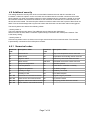
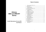
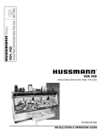
SMS alarm controller
User manual
Version: 02 Rev 01
Date: 9.10.2012
Released for: official
Created by: G-Systems Engineering ood
Page 1 of 16
Table of contents
1 Description.........................................................................................................................3
1.1 Functions....................................................................................................................3
2 Technical data....................................................................................................................3
3 Initial operation...................................................................................................................3
4 SMS alarm controller..........................................................................................................5
4.1 Port 1 – port 10...........................................................................................................5
4.2 LEDs...........................................................................................................................5
4.3 Internal key switch......................................................................................................5
4.4 Backup battery............................................................................................................5
4.5 Housing protection......................................................................................................5
4.6 Reset to factory settings.............................................................................................6
4.7 Storing phone numbers..............................................................................................6
4.8 Additional security.......................................................................................................7
4.8.1 Numerical codes..................................................................................................7
5 SMS commands.................................................................................................................8
5.1 Status enquiry.............................................................................................................8
5.2 Change system language...........................................................................................8
5.3 Storing an additional phone number...........................................................................8
5.4 Temperature and humidity sensor..............................................................................9
5.5 Switchable multi-socket outlets................................................................................10
5.6 Alarm delay...............................................................................................................10
5.7 Additional security configuration...............................................................................10
5.8 Reset sent alarms.....................................................................................................10
5.9 Release.....................................................................................................................11
5.10 Battery.....................................................................................................................11
5.11 Siren time................................................................................................................11
6 Sensors............................................................................................................................12
6.1 Smoke sensor...........................................................................................................12
6.2 Switchable multi-socket outlet..................................................................................12
6.3 Motion sensor...........................................................................................................13
6.3.1 Additional settings on the motion sensor...........................................................13
6.4 Water sensor.............................................................................................................15
6.5 Magnetic contact.......................................................................................................15
6.6 Temperature and humidity sensor............................................................................15
6.7 Gas alarm.................................................................................................................15
6.8 Glass alarm...............................................................................................................15
6.9 Sirene........................................................................................................................15
7 Error messages ..........................................................................................................................16
Page 2 of 16
1 Description
Thank you very much for purchasing the G-Systems SMS alarm controller. The controller is an easy-to-use
standalone alarm system with alarm output via SMS. The device provides ten independent input / output
ports. By virtue of its many sensors and its individual terminal assignment, the controller meets all
requirements. The controller offers additional functions such as the option to store up to five phone number's
and to switch any standard 230V device on or off via SMS.
1.1 Functions
Alarm via SMS
• Smoke detector
• Motion detector
• Water sensor
• Temperature / humidity monitoring
• Magnetic RED contacts (for windows, doors, etc)
• Power failure
• External alarm system
• Gas detector
• Glass break detector
• Alarm siren acoustic and light
➢ Automatic sensor detection at each of the ten ports.
➢ Data transmission security adjustable from normal to encoded
➢ SMS control of up to ten 230 V multi-socket outlets
➢ Minimum and maximum temperature and air humidity adjustable via SMS.
➢ Storage for up to 5 phone numbers (1 master, 4 slave)
➢ Retrievable controller status
➢ Language selection English / French or Portugese or German
➢ Adjustable delay time (0 … 180 seconds) before alarm is armed
2 Technical data
Power adapter: 100 – 240 V / 50 – 60 Hz
Supply voltage: 12 VDC +/- 10 %
Supply current: Min. 1A
Temperature range: 10 °C to 50 °C
Humidity range: 0 % to 95 %
GSM frequencies: 900 / 1800 / 1900 MHz
Dimensions (L x W x H): 80 x 140 x 78 mm
3 Initial operation
Before operating the system for the first time, the following check points must be observed in order to
guarantee a trouble-free function:
➢
➢
➢
➢
➢
➢
➢
SIM card configuration
• Insert the SIM card that you want to use in any mobile phone and set the PIN code to 0000.
• Please delete all SMS messages, or else they will be deleted by the SMS controller.
After completing the SIM card configuration you can unscrew the lid of the controller and remove the
lid.
Insert the configured SIM card in the SIM card holder. Its chamfered edge must face the edge of the
housing.
Insert a 9 V block battery in the corresponding battery compartment
Important: Verify the battery is connected with the correct polarity.
Set the internal key switch to OFF
Plug the power adapter supplied with the system into a wall outlet and connect the other end with
the controller.
Page 3 of 16
➢
➢
➢
➢
➢
➢
➢
➢
Wait for the controller to start up. This can be seen from the status LED which stops blinking and
lights up continuously. Should, in addition, the error LED light up, refer to section 7 (error
messages).
Now press the programming key (top right) for 1second. so that the status LED resumes blinking.
Now you have two minutes, while the status LED continues blinking, to use your mobile phone to call
the SIM card inserted in the controller.
Let the phone ring until the controller ends the connection. If this step is completed successfully, the
power / status LED will again light continuously. After a short while, you will receive an
acknowledgement via SMS.
Disconnect the controller from the power supply and wait until it has shut down.
Now fit back the housing lid and tighten the screws.
Place the controller at a location with good GSM reception.
• The controller sends an SMS if the reception quality falls below 20 %.
• If the controller is unable to find a network, the error LED will light up and indicate the error
number 5 (see section 7 error messages).
Now plug in all sensors to be used at the controller.
The controller is now ready for operation and can be used. You may personalise the controller as needed to
match your application by means of SMS configuration commands. These commands are described in detail
in section 5 (SMS commands).
Page 4 of 16
4 SMS alarm controller
4.1 Port 1 – port 10
The SMS alarm controller provides ten independent input / output ports. Any sensor can be connected to any
port. The controller detects and installs the sensors automatically when they are connected to a port.
4.2 LEDs
The controller provides ten port LEDs, one power LED and one error LED in order to indicate the operating
mode, errors and sensor data.
➢
Power / status LED:
This LED indicates the controller status.
• If the LED lights continuously, the controller is ready for operation.
• A slowly blinking LED indicates that the controller is starting up upon connection to the mains
supply. After pressing the programming key, the same blinking pattern indicates that the
controller is waiting for an incoming call to store the number. .
➢
Error LED
The error LED indicates an error condition. The various errors are explained in section 7 (error
messages).
➢
Port 1 to port 10 LEDs:
Each port has its own LED. It indicates the port status.
• If the LED is not lit, no sensor is connected to the respective port.
• If the LED lights continuously, a sensor is connected and has been detected by the controller.
• A fast blinking LED indicates that the controller is armed and the sensor connected to this port
has triggered an alarm. The LED stops blinking when the controller is disarmed and the key
switch is set to OFF. Or the triggered alarm can be reset by sending an SMS section 5.8 (reset
sent alarms).
• A slowly blinking LED indicates that an external key switch is connected to the port and set to
OFF position.
4.3 Internal key switch
The controller can be armed (on) or disarmed (off) by means of the internal key switch.
• When the switch is set to ON, the controller will be armed after the specified delay time. This delay
time allows the user to leave the room without generating an immediate alarm. The delay time can
be configured through an SMS command. See section 5.6 (alarm delay). Once the delay time has
expired, the controller changes to armed mode.
• When the switch is set to OFF, the controller is disarmed immediately. All alarms are reset, and the
control system changes over to the disarmed mode.
4.4 Backup battery
A 9 V block battery must be inserted in the housing in order to prevent the armed controller from shutting
down in the event of a power failure or when the power supply is disconnected. If the power supply is no
longer available while the controller is armed and with a backup battery inserted in the controller, an alarm
message will be sent via SMS. Subsequently, the controller shuts down until the power supply is restored. It
should be noted that, without mains supply, the sensors are no longer operative and the power supply to the
controller needs to be checked on site. 6
4.5 Housing protection
When the controller is armed and the lid of the housing is opened, an alarm is triggered immediately and you
will be notified with an SMS.
Page 5 of 16
In order to prevent unwanted false alarms, ensure that the controller is disarmed before opening the housing.
4.6 Reset to factory settings
Follow the steps below to reset the controller to the factory settings:
• - Connect the controller to the power adapter
• - Set key switch to OFF position.
• - Wait for the controller to start up
• - Press the button for 1sec.
• - Press it again until the error LED (red) starts flashing quickly.
If the reset sequence has been correctly performed, the controller will restart and all values will be restored
to the factory settings. The controller sends back an acknowledgement upon successful completion of the
command.
4.7 Storing phone numbers
Follow the steps below to store your master-phone number in the controller:
• Connect the controller to the power adapter
• Set key switch to OFF position.
• Open the controller cover
• Press the programming key for 1sec. (press key only when the controller has started up and the
power / status LED lights continuously).
• The status LED should now blink slowly. If this is the case, call the number of the SIM card inserted
in the controller.
• Wait until the controller ends the connection. The status LED will now light continuously, and an SMS
is sent to the stored number as an acknowledgement.
• Upon completion of this sequence, the number is stored in the controller. If you want to store an
additional number, please refer to section 5.3 (storing an additional phone number).
Page 6 of 16
4.8 Additional security
This setting allows the security level of the communication between the user and the controller to be
increased. It offers two options. On the one hand one can select that the controller connects to the mobile
phone network only when a messages needs to be sent. Subsequently the connection is ended. As a result
the controller remains connected to the network for not more than 45 seconds and, in most instances, the
device cannot be located. The second option will allow numerical codes to be sent in place of alarm texts via
SMS. This has the advantage that only the user knows what has been sent and which alarm was triggered.
The security status can assume the following values:
- Security status: 0
This is the standard security status. The additional security features are deactivated.
Alarms are sent as texts, and the controller is permanently connected to the mobile phone network. This
is the factory setting.
- Security status: 2
If the security status is set to 2, alarms are no longer sent as texts but as numerical codes. The controller
is permanently connected to the mobile phone network.
4.8.1 Numerical codes
Numerical
code
Description / alarm
Numerical
code
Description / alarm
10
Smoke sensor
34
Lamp over-temperature sensor removed
11
Water sensor
35
Temperature and humidity sensor removed
12
Magnetic switch
36
External key switch has been removed
13
Motion sensor
370 / 371
Switchable multi-socket outlets removed
14
Lamp over-temperature
50
Controller opened
15
Over-temperature
51
Power failure / controller to standby
16
Negative-temperature
52
Low battery voltage
17
Humidity too high
53
No battery connected
18
Humidity too low
54
Poor SMS reception
300 / 301
Smoke sensor removed/connected
55
Programming key activated
310 / 311
Water sensor removed/connected
56
Key switch inserted
320 / 321
Magnetic switch removed/connected 57
330 / 331
Motion detector removed/connected
Page 7 of 16
Wrong key position See user manual
5 SMS commands
Almost all controller settings can be made via SMS. With regard to the SMS communication between user
and controller one should keep in mind that each SMS must not comprise more than 70 characters. The
controller does not support multi-part SMS.
The samples listed below show examples how to apply the command.
5.1 Status enquiry
This SMS command allows you to retrieve the controller status at any time and recall the most important
pieces of information.
Syntax for retrieving the current status:
• State
Simply send the word 'State’ to the controller.
If the message is correctly received, you will get a reply with the following data:
➢ Alarm status: (On or off)
This value shows whether the controller is armed (on) or disarmed (off)
➢
Reception (0 – 100 %)
This value indicates the reception quality at the device
➢
Battery voltage (Value in volts)
Indicates the current battery voltage
➢
Sent alarms: (0 - 10)
Indicates the number of alarms sent since the system was last armed
If a temperature and humidity sensor is used, the following additional values are indicated:
➢ - Temperature: (Temperature in degrees Celsius)
Indicates the current room temperature
➢
Humidity (Relative humidity in percent)
Indicates the current humidity in the room air
If a multi-socket is used, the following additional values are indicated:
➢ - Port [x] is Off or On
5.2 Change system language
Factory setting: English, the SMS alarm can have one more language for example French, German,
Portuguese
Syntax for change language:
• Français French German Deutsch Portuguese Português
Simply send the Language you desire to the controller which support it.
5.3 Storing an additional phone number
4 Four additional phone numbers can be stored in addition to the main telephone number. This can also be
carried out by sending a configuration SMS. When an additional number is used, all alarm-messages are
always sent to all numbers. Only the master phone number can be used to carry out configuration changes.
SMS activation syntax:
2nd no (phone number of additional mobile phone)
➢ Example:
• 2 no +41234567890
Page 8 of 16
• 3 no +41234567891
• 4 no +41234567892
• 5 no +41234567893
Choose one of the empty entries to store and activate an additional telephone number.
SMS deactivation syntax:
2nd no [enter a 0 (zero) as phone number]
➢ Example:
• 2 no 0
• 3 no 0
• 4 no 0
• 5 no 0
Choose one of the three variants to deactivate an additional telephone number. Factory setting: 0
(deactivated) Both commands will be acknowledged after successful completion.
5.4 Temperature and humidity sensor
The following parameters of the temperature and humidity sensor can be configured by sending SMS
messages. In order to use the sensor for temperature measurements only, the humidity function can be
disabled by setting the maximum value to 100 % and the minimum value to 0 %.
➢
The temperature and humidity ranges are as follows:
Temperature: -50°C to 150 °C
Humidity: 10 % to 95 % (not condensing)
SMS syntax for the maximum temperature value to trigger an alarm:
➢ - Temp Max [maximum temperature in degrees]
• Temp max 30
Range: -50°C to 150 °C
SMS syntax for the minimum temperature value to trigger an alarm:
➢ Temp Min [minimum temperature in degrees]
• Temp min -2
Range: -50°C to 150 °C
SMS syntax to extract the actual temperature:
➢ Actual temperature in degrees
• Temp
SMS syntax for the maximum humidity value to trigger an alarm:
➢ RH Max [maximum humidity in percent]
• Rh max 80
Range: 0 % to 100 %
SMS syntax for the minimum humidity value to trigger an alarm:
➢ RH Min [minimum humidity in percent]
• Rh min 30
Range: 0 % to 100 %
SMS syntax to extract the actual hunidity:
➢ Actual humidity in Rh % (Rh=relative Humidity)
• Humidity
Factory settings:
➢ Maximum temperature : 35 °C
➢ Minimum temperature: 16 °C
➢ Maximum humidity: 100 % (i.e. deactivated)
Page 9 of 16
➢
Minimum humidity: 0 % (i.e. Deactivated)
The controller sends back an acknowledgement upon successful completion of the command.
5.5 Switchable multi-socket outlets
The following commands can be used to control the switchable multi-socket outlets via SMS messages.
SMS syntax for the multi-socket outlets:
➢ Port [port number (1 – 10) to which the multi-socket outlet is connected] [followed by 1 for ‘on’ and 0
for ‘off’]
•
Example for switching on a multi-socket outlet connected to port 3:
Port 3 1
•
Example to switch off a multi-socket outlet connected to port 3:
Port 3 0
The controller sends back an acknowledgement upon successful completion of the command.
5.6 Alarm delay
This option is used to set two parameters. On the one hand the time between the arming command (key
switch to ON position) and the actual arming of the controller. On the other hand the time after an alarm is
triggered until the controller is disarmed (key switch to OFF position). Both times are equal and can be
configured as described below.
Due to this delay time it is possible to leave the controlled area after arming the system and to enter the
room without causing an immediate alarm. The disarming delay is restricted to the motion sensor and
magnetic contacts. An SMS message will be sent immediately in the case of all other alarms. This function
can be deactivated by setting a time of 0 seconds.
➢
Syntax to set the delay time:
•
Delay time [time in seconds]
Time delay 30
Range: 0 to 180 seconds
Factory setting: 15 seconds
5.7 Additional security configuration
This function allows you to set the security index.
Syntax to set the additional security index:
➢ Security [security index]
• Security 2
Value: 0 or 2
Factory setting: 0
5.8 Reset sent alarms
Each sensors will alert you one time when they have been triggered. In order to recieve new alerts from the
same sensor it is necessary to reset the alarm by turning the key to the OFF position or by sending an SMS
to confirm that the alert has been seen. You will then be notified if the alarm is triggered again and all
triggered ports will be reset (blinking LED).
• clear
Page 10 of 16
5.9 Release
Send the comand release to get the latest software version.
• Release
5.10
Battery
Send the comand battery to get the actual battery tension.
• Battery
Range: 8.9V to 9.5V good <8.9V replace new battery
5.11
Siren time
SMS syntax for the siren time value to trigger the duration:
➢ Siren time [value in seconds]
• Siren time 30
Range: 1sec to 250sec
Page 11 of 16
6 Sensors
This section gives a brief overview of all sensors and their use. The controller is only compatible with Gsystems sensors. Only these sensors must be used. The function is no longer guaranteed if sensors are
modified or if other sensors are used.
6.1 Smoke sensor
The smoke sensor is a photoelectric smoke detector. The sensor sends a silent alarm to the controller. It
does not provide a siren.
Technical data:
Functional area: 20 m2
Temperature range: 0 °C to 50 °C
Humidity range: 0 % to 95 %
Installation:
1. Use the included screws to fasten the holder to the ceiling at a suitable location, typically in the centre
of the room.
2. Subsequently, insert the smoke sensor in the holder.
3. Route the cable to the controller and connect it to a free port.
4. You can now check the sensor function by blowing some smoke into the sensor or by pressing the test
button located on the side of the smoke detector.
Information:
- The smoke detector cannot be used under adverse conditions,
e.g. extremely cold or hot or hazy ambient conditions
- The smoke detector should be checked once per month
- Please clean the sensor once every six months with a soft brush or similar cleaning implement
Subsequently, verify the functioning of the sensor
6.2 Switchable multi-socket outlet
The switchable multi-socket outlet is not a sensor and therefore cannot trigger an alarm. However, there is
the possibility to switch any electrical device which can be connected to a standard socket outlet ON and
OFF.
The switchable multi-socket outlet provides two connecting cables. There is one standard 230V cable which
can be plugged into a wall outlet. The second cable is fitted with a controller sensor plug for connection to a
controller port. Up to ten switchable multi-socket outlets can be connected and operated at the same time.
Please read the instructions in section 5.5 ‘switchable multi-socket outlets’ for information how to switch
the multi-socket outlet ON or OFF by sending SMS commands.
Important: The maximum permitted current is 8A at cos φ = 1.
Page 12 of 16
6.3 Motion sensor
The motion sensor is a passive infrared motion detector. The sensor detects the movement of a human or
animal in the controlled zone. The sensor provides a thermal compensation as well as a white light and high
frequency suppression.
Technical data:
Detection angle: 110°
Detection range: 12 m
HF suppression: 10 MHz … 1 GHz at 20 V/m
Sensor: Dual element infrared sensor
Installation height: 1.7 m to 2.5 m (recommended height: 2.2 m)
Temperature range: 0 °C to 50 °C
Humidity range: 0 % to 95 %
Installation:
1. Use the included screws to fasten the holder to the wall at a suitable location. The sensor should not
be mounted near to doors leading to the outside, or near to pets, direct sun radiation or moving
objects.
2. Fit the motion detector to the holder
3. Route the cable to the controller and connect it to a free port.
4. After connecting to the controller, the sensor requires approx. 60 seconds to start up and perform a
selfcalibration.
5. Subsequently its functioning can be tested
Information:
- Never touch the sensor element inside the housing
- Clean the sensor every few months with a soft brush
Operating range:
6.3.1
Additional settings on the motion sensor
The sensitivity and the internal LED can be adjusted at the motion detector. In order to carry out these
adjustments, the housing of the motion detector has to be opened.
Important: At first verify that the sensor has been disconnected and is no longer energised. When the
housing is open, take care not to touch the printed circuit board. Three jumper sockets (1, 2, 3 see figure
below) allow you to change the following settings:
1. LED jumper
You can use this jumper to decide whether or not you would like the internal LED to light up during an alarm.
• Jumper connecting 1&2: LED lights up during alarm and calibration
• Jumper connecting 2&3: LED always off
Page 13 of 16
2. Relay jumper
This jumper must connect 2&3 or be set to N.C. Otherwise, the correct functioning with the controller cannot
be guaranteed.
3. Pulse jumper
This jumper can be used to define how sensitive the controller is when reacting to movements.
• Jumper connecting 1&2:
The motion sensor is set to maximum sensitivity
• Jumper connecting 2&3:
The sensitivity is set to a medium level. In addition, the high
frequency suppression is set to high
• Jumper open “shut off”
The sensitivity is low and the High frequency suppression is set to
high.
Page 14 of 16
6.4 Water sensor
The water sensor triggers an alarm upon contact with water. It can, for instance, be placed on the floor to
trigger an alarm in the case of the room being flooded with water. The water sensor has two sides. The top
side with markings and connecting cable, and the bottom side with the sensitive sensor surface. A single
drop of water on the sensor surface is sufficient to trigger an alarm.
Important: After an alarm, the sensor should be dried thoroughly to prevent subsequent false alarms.
6.5 Magnetic contact
The sensor is a two-piece magnetic switch. This sensor is especially suited for monitoring windows, doors,
gates, hatches etc. Mode of operation: The magnetic switch must be installed in a manner which ensures
that the two parts separate when, for instance, the door opens. No alarm is triggered when the two parts
touch one another or when they are separated by a very small gap. An alarm will be triggered, however, as
soon as the two parts separate. Ensure that the sensor is well fastened to avoid unnecessary false alarms.
6.6 Temperature and humidity sensor
The temperature and humidity sensor is a digital sensor which measures the current temperature and
humidity. If the temperature or humidity exceeds or falls below the preset alarm values, an alarm will be
triggered. These alarm values for temperature and humidity can be configured as described in section 5.4
(temperature and humidity sensor). Please place the sensor at a suitable location and connect it to any
controller port.
Technical data:
Operating range, temperature: 0 to 50 °C
Temperature tolerance: +/- 1.5 °C
Operating range, humidity: 10 % to 90% (not condensing)
Humidity tolerance: +/- 6%
Limits:
Temperature: -20 to 70 °C
Humidity: below 95 % relative humidity (not condensing)
6.7 Gas alarm
The Gas alarm can detect propan butan gases and in case of dedection the alarm will be triggered
6.8 Glass alarm
The glass alarm only works when the SMS alarm is in the armed position. It works by detecting the sound of
breaking glass using a microphone. The sensitivity can be adjusted with a potentiometer inside the glass
alarm. In case of detection the alarm will be triggered.
6.9 Siren
The siren sounds and the light begins to flash when the alarm is triggered. You can set the duration of the
siren by following the instructions in section 5.11 ‘siren time’
Page 15 of 16
7 Error messages
The table below lists all error messages which the controller is able to display. When an error occurs, the
error LED starts blinking for four seconds before it continues blinking in one-second intervals in accordance
with the error number.
○ Error LED off
● Error LED is lit
Each dot stands for one second ‘on’ or ‘off’. In order to obtain the error number one has to count how many
times during one cycle the error LED is 'off'.
Error no.
Error LED blinking pattern
Description
2
●●○●○●●●●●●○●○●●
There is no phone number available.
Please refer to section ‘Storing a
phone number’.
3
●●○●○●○●●●●●●○●○●○●●
No SIM card available. Check
whether SIM card has been correctly
inserted.
4
●●○●○●○●○●●●●●●○●○●○●○●●
Pin code has not been set to 0000.
Please set PIN code to 0000.
5
●●○●○●○●○●○●●●●●●○●○●○●○●○●●
No network found. Relocate the
controller to a place with better
reception.
●●○●○●○●○●○●○●●●●●●○●○●○●○●○●○●●
Startup failure. Restart the controller.
7
●●○●○●○●○●○●○●○●●●●●●○●○●○●○●○●○●○●●
There is more than one external key
switch connected. Up to one
external key switch can be
connected.
8
●●○●○●○●○●○●○●○●○●●●●●●○●○●○●○●○●○●○●○●● configuration of the GSM module.
An error occurred during the
Please restart the controller.
Page 16 of 16