1
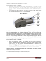
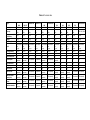
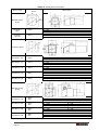
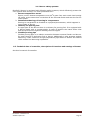
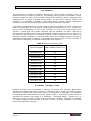
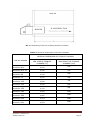
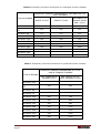
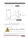
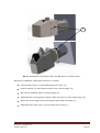
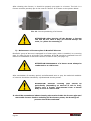
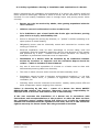
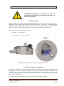
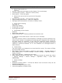
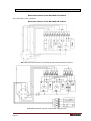
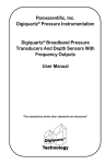
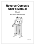
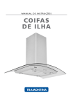
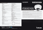
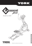
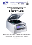
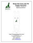
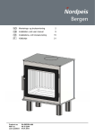
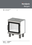
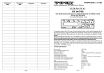
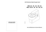
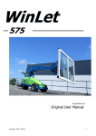
Burner for pellets USER’S MANUAL www.burnpell.com 2013-02-14 Page 2 TABLE OF CONTENTS 1. General information ........................................................................................... 5 1.1. Transportation ............................................................................................. 5 1.2. Storage ...................................................................................................... 5 1.3. Delivered burner condition control ................................................................. 6 1.4. Free space around burner ............................................................................. 6 2. Product description ............................................................................................ 7 2.1. Burner contruction ....................................................................................... 7 2.1.1. BurnPell X Mini ...................................................................................... 7 2.1.2. BurnPell X ............................................................................................ 8 2.1.3. BurnPell X Big ....................................................................................... 9 2.2. Pellets fuel quality requirements .................................................................. 10 2.3. Technical data of burner ............................................................................. 11 2.4. Burner safety systems ................................................................................ 15 2.5. Technical data of controller, description of functions and burner settings ........... 15 3. Installation...................................................................................................... 16 3.1. Chimney ................................................................................................... 16 3.2. Boiler / furnace / oven................................................................................ 16 3.3. Fuel hopper............................................................................................... 19 3.4. Auger ...................................................................................................... 20 3.5. STB protection .......................................................................................... 21 3.6. Boiler temperature sensor ........................................................................... 21 4. Assembly of burner and feeder .......................................................................... 22 5. Additional connections ...................................................................................... 26 6. Exploitation and safety regulations ..................................................................... 27 6.1. Exploitation ............................................................................................... 27 6.2. Safety regulations referring to installation and exploitation of burner .............. 29 6.3. Guarantee................................................................................................. 30 7. Service of devices ............................................................................................ 31 7.1. Photosensor .............................................................................................. 31 7.2. Electrical igniter replacement ...................................................................... 31 7.3. External feeder cleaning ............................................................................. 32 7.4. Burner cleaning ......................................................................................... 32 8. Reasons of improper operation .......................................................................... 33 9. Electrical schemes............................................................................................ 34 10. Collection report ............................................................................................ 35 11. List of pictures and tables ............................................................................... 36 12. Notes ........................................................................................................... 37 BurnPell X – Pellet burners www.burnpell.com Page 3 Page 4 1. General information Read carefully the user’s manual before activation of burner. BurnPell X burner requires installation according to this user’s manual. Following advices included in this USER’S MANUAL will guarantee safe functioning and installation of the device. All doubts and ambiguities as to condition of equipment or given functions of parts of burner should be reported to the seller in order to get explanations. Installation of burner should be carried out by an authorized and trained by the producer service person. Improper installation may lead to loss of guarantee. Every user of heating boiler devices should know and comply to all local rules of law. Particularly before activating a heating installation in accordance with construction law. The seller does not bear any responsibility for burner installation, which is not in accordance to valid local regulations and for lack of required protocols and permissions. 1.1. Transportation BurnPell X type burner is packed in one carton box with two sections (burner with a controller, mounting flange and a feeder). The device must be carried in packaging, according to markings on the parcels. During transportation it should be protected against unfavorable conditions of environment (snow, rain, dust) and it should not be exposed to shocks, hits and the packaging should be protected against damages. Loading and unloading must be carried out in a way, which does not expose the devices to shocks. Improper loading, unloading and transportation (throwing, rapture sliding, crushing with other heavy goods) can be a cause of damage to the product. In case of damage of the packaging or product, the device should be subjected to control in operation. In case when improper work of a fan or feeder motor is observed (loud work, rubbing), possibly other faults, e.g. electronics (vanishing of characters on display of LCD display) the burner should be sent to the service team in order to carry a reparation. Consignments delivered by forwarding companies should be checked in presence of the messenger when the goods are delivered. In case of any incompatibilities a protocol should be prepared. 1.2. Storage BurnPell X burner should be stored in environmental conditions in accordance to following guidelines: Dry and draughty rooms, free from substances like gases, corrosive liquids and fumes, which are harmful to burner. Burner and feeder cannot be stored in rooms where artificial fertilizers, chlorinated lime, acids, chemicals etc. are kept. Best storage temperature from +5OC to +40OC. Relative humidity should not exceed 70%. BurnPell X – Pellet burners www.burnpell.com Page 5 During storage, the device cannot have direct contact with the floor. BurnPell X burner until final assembly should be kept in carton and on a pallet. Burners can be stored and transported in two layers maximum. In case when a burner is stored for over 2 years from its production date or in environmental conditions not suitable with above description, before installing it should be subject to activating by an authorized service person. To testify proper quality and safety of a burner, the above inspection will be documented by service person in the guarantee card. 1.3. Delivered burner condition control Before commencing assembly activities check the following: condition of packaging, make sure that there is no visible damages and if delivery is complete and not damaged. Possible reservations and problems should be reported to the supplier immediately. 1.4. Free space around burner According to local safety regulations referring to heating devices, provide free space around burner, at least 0,8 m around boiler. Provide space for service of burner. The boiler room should be clean, dry and well aired. Airflow to the boiler should be at least equal to exhaust of fumes through the chimney. ATTENTION! In order to minimize the risk of fire do not store flammable materials near the burner (min. distance 0,5 m). Page 6 2. PRODUCT DESCRIPTION BurnPell X is a brand under which since 2001 burners for biomass have been produced. These products are characterized with steeples regulation of settings allowing for usage in all types of ovens or heating boilers. In case when exchange of burner is done in an old boiler, then it is not necessary to make changes in existing installation. Firing up, sustaining fire after reaching preset temperature and feeding fuel is automatic. Unique solutions used in BurnPell X burners are patented technologies of overpressured burning, which eliminate problem of back burning, patented system of fuel mixing in burning chamber, which prolongs the time of maintenance-free work, it is also a broadband lambda probe – available to all types of burners – which improves burning process and reduces fuel consumption. BurnPell X burners are used in households, bakeries, hotels, public utilities, schools and production halls or warehouses. They are made of acid-proof steel and they are equipped in best quality parts available on the market. The product, which you have at your disposal, is the highest quality, most technologically advanced burner available on the market. 2.1. Burner construction BurnPell X burners are divided into 3 groups: 1. BurnPell X Mini 2. BurnPell X 3. BurnPell X Big 2.1.1. BurnPell X Mini 1 2 3 4 5 Pic. 1. Construction of BurnPell X Mini burner. BurnPell X Mini burner is build from two parts: inner part - burning chamber (1) and outer part, which is covered by steel plate (5). Under the cover the blowing chamber is located, in which igniter for burning up fuel is mounted, together with a fan, socket for electrical connections and electronics. Multi socket (4) is located on top of the burner; plug of the controller is connected into it. In top part of the cover there is a pouring pipe (3), to which a plastic pipe, connecting burner with fuel hopper, is mounted. The cover of burner does not have any protruding and sharp parts. It does not threat one’s health. The temperature of burner’s cover during operation should not exceed 50ºC with BurnPell X – Pellet burners www.burnpell.com Page 7 exception of places of raised temperature, i.e. bakery. Burning chamber is made of two parts: Removable grate, made of heat-resistant steel, with holes of air intake to grate finished inside with a wall with holes for air supply, a hole for heater which burns up fuel, a hole for flame sensor and inner pipe, in which a spiral feeding fuel to furnace. Covering part (2) made of stainless steel, which serves as a coat, making space for free airflow into furnace, which is cooled and aired. 2.1.2. BurnPell X 1 2 3 4 5 Pic. 2. Construction of BurnPell X burner. BurnPell X burner is built from two main parts: inner pipe, which is a burning chamber (1) and outer part, which is covered with acid-resisting steel plate (5). Under the cover, there is a blowing chamber with an igniter for burning up fuel and a fan, a socket for electrical connections and electronics. On the right side of burner, there is a multi-socket protruding (4) to which the plug of the controller is connected. In upper part of the cover, there is a pouring chimney with barrier (3). To the chimney a pipe connecting with fuel feeder is connected. The cover of burner does not have protruding, sharp parts and does not threat one’s health. The temperature of cover during operation should not exceed 50ºC with exception of places of raised temperature, i.e. bakery. Burning chamber is made of two pipes: Inner pipe of furnace, made of heat-resistant steel with holes for airflow to furnace, finished from inside with a wall with holes for air intake, a hole for igniter which burns up fuel, hole for flame sensor and outside pipe, in which there is a spiral for feeding fuel to furnace. Outside covering pipe (2) made of stainless steel, which serves a role of a coat creating space for free airflow among pipes, which cools and airs the furnace. Pouring chimney is mounted to rectangular hole in upper part of the burner’s cover. Inside the chimney there is a steel barrier with counterweight. The barrier prevents against back burning to the feeder. It is important that counterweight is not blocked in any way. Page 8 2.1.3. BurnPell X Big 1 2 3 4 Pic. 3. Construction of BurnPell X Big burner. 5 BurnPell X Big burner is built from two main parts: inner part, which is a burning chamber (1) and outer part, which is covered with steel plate (5). Under the cover, there is a blowing chamber with an igniter for burning up fuel and a fan, a socket for electrical connections and electronics. On the right side of burner, there is a multi-socket protruding (4) to which the plug of the controller is connected. In upper part of the cover, there is a pouring chimney with barrier (3). To the chimney a pipe connecting with fuel feeder is connected. The cover of burner does not have protruding, sharp parts and does not threat one’s health. The temperature of cover during operation should not exceed 50ºC with exception of places of raised temperature, i.e. bakery. Burning chamber is made of two parts: Removable furnace, made of heat-resistant steel, with holes for airflow to furnace, finished from inside with a wall with holes for air intake, a hole for igniter which burns up fuel, hole for flame sensor and inside pipe, in which there is a spiral for feeding fuel to furnace. Covering part (2) made of stainless steel serving as a coat, making space for free airflow to furnace, which is cooled and aired. Pouring chimney is mounted to rectangular hole in upper part of the burner’s cover. Inside the chimney there is a steel barrier with counterweight. The barrier prevents against back burning to the feeder. It is important that counterweight is not blocked in any way. ATTENTION! The producer reserves the only right to implement changes in construction of burner and feeder, its software and wiring, otherwise he is released from any responsibility towards the buyer. BurnPell X – Pellet burners www.burnpell.com Page 9 2.2. Pellets fuel quality requirements In table below given requirements as to quality of pellet fuel are shown. Using fuel, which complies to DIN 51731 or DIN PLUS, extends longevity of burner. Table 1. Quality requirements of pellet fuel. Wooden pellets Quality criteria Units NORM DIN plus DIN 51731 Diameter mm 4≤d<10(6) 4≤d<10(6) Lenght mm 5 x D(3) <50 Density kg/dm³ 1,12 1,0-1,4 Ash % <0,5(1);(7) <1,50 Humidity % <10 <12 Humidity when delivered % Not specified Not specified MJ/kg >18(1) 17,5 – 19,5 (2) Sulphur % <0,04(1) <0,08 Nitrogen % <0,3(1) <0,3 Chlorine % <0,02(1) <0,03 Dust collected % <2,3 - Additives facilitating pressing % <2(8) (4) - Not specified Not specified Arsenic mg/kg <0,08 <0,08 Lead mg/kg <10 <10 Cadmium mg/kg <0,5 <0,5 Chrome mg/kg <8 <8 Copper mg/kg <5 <5 Quicksilver mg/kg <0,05 <0,05 Zink mg/kg <100 <100 Halogens mg/kg <3 <3 Caloric value Temperature of melting ash (1) Dry weight (2) Free from water and dust (3) No more than 20% of pellets can be as long as 7,5 x diameter (4) Page 10 DIN forbids to use additives. This ban is not valid to small heating systems (5) In warehouse of the producer (6) Tolerance in differences in diameter ± 10 % (7) Allowed content of dust up to 0,8%, if it is naturally higher, specific for given sort of wood (8) Only natural additives from biomass are allowed 2.3. Technical data of burner Main properties of BurnPell X burner: Safety Patented technology of overpressure burning – no risk of backfiring Control over temperature of burner Possibility of installing an air filter Barrier with a counterweight preventing against back burning Reliability Patented system of fuel mixing in burning chamber – significantly prolongs maintenance-free operation Automatic start after electricity shortage – last settings memory Furnace made of highest quality heat-resistant steel Made of the best materials, using latest technologies Modern controlling system Automatic operation: firing up, cleaning, flame control Stepless (electronic) power regulation Possibility of control over burning process by broadband lambda probe (optionally) Low emission of CO and CO2 Low consumption of electricity Low heat inertia High burning efficiency – up to 99 %! Fully compatible with automatics of oil and gas boiler and with bakery oven Flame sensor precisely detecting its level Possibility of handling the chimney exhaust fan. The fan works periodically and does not ventilate the boiler. BurnPell X – Pellet burners www.burnpell.com Page 11 Table 2. Technical data. Type: Power output: Currency: Average consumption of electricity: Weight: Feeder lenght: Fuels: Burning efficiency: Efficiency in boiler: Power modulation: Lambda probe: CH pump service: HUW pump service: Mixer service: Buffer service: Additional feeder service (silo): Room temperature sensor: Weather automatics: BurnPell X Mini 5 - 26 kW 230 V AC / 50Hz BurnPell X Mini 35 8 - 35 kW 230 V AC / 50Hz 15 - 70 kW 230 V AC / 50Hz BurnPell X 100 30 - 100 kW 230 V AC / 50Hz 10 - 44 kW 230 V AC / 50Hz 60 W 60 W 60 W 75 W 11 kg 2m Pellet 6-8mm Oat Dry pit to 96 % to 96 % YES YES (optional) YES YES YES YES (optional) YES (optional) YES (optional) YES (optional) 15 kg 2m Pellet 6-8mm Oat Dry pit to 96 % to 96 % YES YES (optional) YES YES YES YES (optional) YES (optional) YES (optional) YES (optional) 19 kg 2m Pellet 6-8mm Oat Dry pit to 99 % to 96 % YES 20 kg 2m Pellet 6-8mm Oat Dry pit to 99 % to 96 % YES BurnPell X 44 BurnPell X 70 YES (optional) YES (optional) YES YES YES YES YES YES YES (optional) YES (optional) YES (optional) YES (optional) YES (optional) YES (optional) YES (optional) YES (optional) 40 - 120 kW 230 V AC / 50Hz BurnPell X 150 50 - 150 kW 230 V AC / 50Hz BurnPell X 190 65 - 190 kW 230 V AC / 50Hz BurnPell X 260 80 - 260 kW 230 V AC / 50Hz BurnPell X 350 100 - 350 kW 230 V AC / 50Hz 120 - 500 kW 75 W 75 W 75 W 120 W 120 W 150 W 150 W 25 kg 2m Pellet 6-8mm Oat Dry pit to 99 % to 96 % YES YES (optional) YES YES YES YES (optional) YES (optional) YES (optional) YES (optional) 27 kg 2m Pellet 6-8mm Oat Dry pit to 99 % to 96 % YES 35 kg 2m Pellet 6-8mm Oat Dry pit to 99 % to 96 % YES YES (optional) YES YES YES YES (optional) YES (optional) YES (optional) YES (optional) 55 kg 3m Pellet 6-8mm Oat Dry pit to 99 % to 96 % YES 61 kg 3m Pellet 6-8mm Oat Dry pit to 99 % to 96 % YES 80 kg 3m Pellet 6-8mm Oat Dry pit to 99 % to 96 % YES 100 kg 3m Pellet 6-8mm Oat Dry pit to 99 % to 96 % YES YES YES YES YES YES YES YES YES (optional) YES (optional) YES (optional) YES (optional) YES YES YES YES (optional) YES (optional) YES (optional) YES (optional) YES YES YES YES YES YES BurnPell X 120 YES (optional) YES YES YES YES (optional) YES (optional) YES (optional) YES (optional) BurnPell X 550 230 V AC / 50Hz YES (optional) YES (optional) YES (optional) YES (optional) YES (optional) YES (optional) YES (optional) YES (optional) BurnPell X burner has simple and compact construction, which allows for easy assembly in boiler’s door. Below in the table: the dimensions and drawings of mounting holes for given types of burners. There are 3 groups of burners: BurnPell X Mini group: - BurnPell X Mini - BurnPell X Mini 35 BurnPell X group: - BurnPell X 44 - BurnPell X 70 - BurnPell X 100 - BurnPell X 120 - BurnPell X 150 BurnPell X Big group: - BurnPell X 190 - BurnPell X 260 - BurnPell X 350 - BurnPell X 500 Table 3. Dimensions of burners. Burner type Drawings of mouting holes Dimensions BurnPell X Mini group BurnPell X Mini D - Ø155 BurnPell X Mini 35 D - Ø173 A B C A B C – – – – – – 215 508 125 235 529 140 A B C A B C A B C A B C A B C – – – – – – – – – – – – – – – 250 619 Ø169 250 619 Ø169 285 654 Ø204 355 724 Ø204 355 724 Ø219 A B C A B C A B C A B C – – – – – – – – – – – – 339 963 Ø250 356 1022 Ø260 356 1057 Ø300 358,50 1241 Ø350 BurnPell X group BurnPell X 44 D - Ø173 BurnPell X 70 D - Ø173 BurnPell X 100 D - Ø210 BurnPell X 120 D - Ø210 BurnPell X 150 D - Ø225 BurnPell X Big group BurnPell X 190 G - Ø260 H - 268 BurnPell X 260 G - Ø270 H - 268 BurnPell X 350 G - Ø310 H - 287 BurnPell X 500 G - Ø360 H - 287 Page 14 D – 327 E – 240 F – 297 D – 327 E – 240 F – 297 D – 357 E – 259 F – 316 D – 491 E – 352 F – 408 2.4. Burner safety systems BurnPell X burner is equipped with following safety systems, which effectively protect the user against back burning. The main protections are: 1. Burner temperature sensor Burner, once it detects temperature over 90OC goes from work mode into burning off mode, at the same time it switches off the external feeder and sets the fan for 100% power. 2. Patented technology of burning in overpressure Burning in overpressure is founded on a physical phenomenon, which happens in inner feeder of burner. 3. Chimney for pouring fuel In upper part of the burner there is a chimney for pouring fuel. It is equipped with a barring hatch with a counterweight. In case of backfire the hatch closes inlet and also prevents fire against reaching the fuel hopper. 4. Flexible pouring pipe Flexible pouring pipe is an elastic connection between external feeder and burner. Its main function is delivering fuel to burner, additionally it also protects against backfiring. Under influence of high temperature pipe starts to deform and extend which makes fuel delivering impossible. 2.5. Technical data of controller, description of functions and settings of burner See User’s manual of controller. BurnPell X – Pellet burners www.burnpell.com Page 15 3. Installation 3.1. Chimney The parameters of chimney should be adjusted to requirements of heating device, of which fumes are led away to chimney. The chimney can be made of ceramics or steel. Chimney should be clean, and its draft sufficient for BurnPell X burner operating with heating device in scope of preset power output. In case when chimney draft is not sufficient, it is possible to install a mechanical fumes exhaust. Before exploitation chimney should be checked and approved by a qualified chimney-sweeper. It should be remembered that a high chimney with big capacity of fumes needs more heat and temperature of inner part of it should not be lower than 80 ºC, 1 m below the top to avoid condensation on top of the chimney. To reduce the inner profile of the chimney, a steel pipe with proper diameter can be installed. All advice referring to chimney duct should be taken from a professional company. Strong wind, too high or too low chimney has influence on efficiency of burner and its settings. In such cases it is advised to install a stabilizer of chimney draft, which will ventilate chimney and help in maintaining stable draft. If chimney is too small, then burner may not work correctly, in such case it is necessary to install a mechanical fumes exhaust. Table 4. Minimum chimney draft. TYPE OF BURNER MIN CHIMNEY DRAFT [Pa] BurnPell X Mini 15 BurnPell X Mini 35 20 BurnPell X 44 25 BurnPell X 70 30 BurnPell X 100 30 BurnPell X 120 30 BurnPell X 150 35 BurnPell X 190 35 BurnPell X 260 40 BurnPell X 350 40 BurnPell X 500 55 3.2. Boiler / furnace / oven BurnPell X burner can be installed in majority of boilers with efficiency about 80%. Installer must adjust the power of burner in relation to boiler power. It is best to mount the burner in boiler’s door, just above grate or in sidewall if it is possible. The diameters of mounting holes of BurnPell X burner are given in table 3. The length of pipe in boiler is regulated by installer with usage of a connector – mounting flange – similar as in oil boilers or directly into door of boiler with 4 M8 screws. Thanks to connector it is possible to regulate length of furnace pipe of burner in boiler. If boiler chamber is too small, burner may operate incorrectly. Page 16 BOILER BURNER FLAME DIRECTION Pic. 4. Positioning of burner including direction of flame Table 5. Minimum dimensions of furnace chamber. MINIMUM DIMENSIONS OF FURNACE CHAMBER TYPE OF BURNER MIN. SIZE OF FURNACE CHAMBER [m3] MIN LENGHT OF FURNACE CHAMBER [mm] BurnPell X Mini 0,023 400 BurnPell X Mini 35 0,030 520 BurnPell X 44 0,038 520 BurnPell X 70 0,070 790 BurnPell X 100 0,099 790 BurnPell X 120 0,109 995 BurnPell X 150 0,119 995 BurnPell X 190 0,160 1200 BurnPell X 260 0,260 1200 BurnPell X 350 0,313 1400 BurnPell X 500 0,554 1500 BurnPell X – Pellet burners www.burnpell.com Page 17 Table 6. Exemplary minimum dimensions of rectangular furnace chamber. EXEMPLARY MINIMUM DIMENSIONS OF RECTANGULAR FURNACE CHAMBER TYPE OF BURNER WIDTH A [mm] HEIGHT H [mm] MIN LENGHT OF FURNACE CHAMBER L [mm] 218 262 400 218 262 520 BurnPell X 44 273 327 520 BurnPell X 70 273 327 790 BurnPell X 100 324 388 790 BurnPell X 120 324 388 995 BurnPell X 150 324 388 995 BurnPell X 190 324 388 1200 BurnPell X 260 417 500 1200 BurnPell X 350 417 500 1400 BurnPell X 500 550 660 1500 BurnPell X Mini BurnPell X Mini 35 Table 7. Exemplary minimum dimensions of cylindrical furnace chamber. TYPE OF BURNER MIN. DIAMETER OF CHAMBER [mm] MIN. LENGHT OF FURNACE CHAMBER L [mm] 270 400 270 520 BurnPell X 44 337 520 BurnPell X 70 337 790 BurnPell X 100 400 790 BurnPell X 120 400 995 BurnPell X 150 400 995 BurnPell X 190 400 1200 BurnPell X 260 515 1200 BurnPell X 350 515 1400 BurnPell X 500 680 1500 BurnPell X Mini BurnPell X Mini 35 Page 18 EXEMPLARY MINIMUM DIMENSIONS OF CYLINDRICAL FURNACE CHAMBER Table 8. Pressure in burning chamber. TYPE OF BURNER PRESSURE IN BURNING CHAMBER [Pa] BurnPell X Mini 10 BurnPell X Mini 35 15 BurnPell X 44 20 BurnPell X 70 25 BurnPell X 100 25 BurnPell X 120 30 BurnPell X 150 30 BurnPell X 190 30 BurnPell X 260 35 BurnPell X 350 35 BurnPell X 500 50 3.3. Fuel hopper Fuel hopper can be made of any non-flammable material, i.e. steel. It can have any capacity and should be located in proper distance from burner. In lower part of fuel hopper a spiral feeder in covering pipe is mounted. The slope of feeder should not be bigger than 45o in relation to the floor. Fuel hopper must be covered with a lid, which will protect rotating screw of the feeder against damage, by leftovers. It is forbidden to manipulate on the bottom of the hopper during operation of feeder. It is a threat to body injury – particular to fingers. It must be remembered to refill the fuel hopper with pellets type fuel before activating the burner. Never pour the fuel hopper with damp or disintegrating fuel. It can cause difficulties in operation of burner – burner blockade. BurnPell X – Pellet burners www.burnpell.com Page 19 3.4. Auger 1 3 2 4 8 5 10 7 6 9 Pic. 5. Construction of feeder. Fuel feeder connects fuel hopper with burner. It is made of steel pipes, galvanized or stainless steel with diameter 60 mm or 76 mm and 2 m or 3 m long (it is related to the size of burner). There is a steel spiral inside the pipe driven by electrical engine 230V AC with gearbox. Engine is connected by power cord to appropriate socket located on burner’s controller. Lower part of feeder is mounted in lower part of fuel hopper, and the upper part is connected with burner via polyurethane pipe. Feeder mounting scheme: 1. Connect both pipes (1) and (2) with screw M8 (3) and nuts M8 (4); 2. Screw the spiral (5) on pin (6) and screw it with a nut (7); 3. Insert spiral into pipe and with screws (9) and nuts (10) screw the gearbox (8) with flange of pipe. Pic. 6. Installation of feeder’s auger Page 20 Dosing of fuel is automatic. Feeder operation is cyclic and outer controller operates it. Feeder should be set with maximum angle 45 o in relation to the floor. Flexible, antistatic polyurethane pipe must be withdrawn from the axis of burner at least 30 cm. In case of overheating of pipe (back burning) or its melting, pellet fuel will not be pouring into burner. Lack of fuel will cause burning off. It prevents against spreading fire on fuel hopper and on the rest of boiler room. 3.5. STB protection In case, when oven or boiler does not have its own STB protection, a capillary thermostat could be added to the set. Capillary sensor should be permanently mounted in water coat of the boiler. After reaching critical (95 oC) temperature of boiler, fuel feeder is cut off. In case of restarting the burner the switcher on housing should be reset, before that the cause of switching off due to boiler overheating should be checked, assessed and right steps toward solving the cause of the problem should be taken. 3.6. Boiler temperature sensor Burner is provided together with boiler temperature sensor. Its task is to control firing up and burning off process in burner. It does not refer to burner version destined for bakery ovens. BurnPell X – Pellet burners www.burnpell.com Page 21 4. Assembly of burner and feeder CEILING FUEL HOPPER FEEDER BOILER CONTROLLER PODAJNIK BURNER FLOOR Pic. 7. Scheme of installation in boiler room. Burner and feeder are delivered in ready made state, good for mounting. They are packed in cardboard boxes, which are to be unpacked with care. 1. Mounting burner in boiler ATTENTION! Before starting the dismantling or disassembly all power supply must be disconnected. In order to carry a proper assembly, the burner must be thermically sealed from boiler’s door. Place furnace pipe of burner in mounting hole of boiler and attach it with screws M8 (1) in case of X.Mini burners, Big version with screws M10. Page 22 1 Pic. 8. Installation of Burnpell X Mini and Big burner in boiler’s door. Scheme of installation of BurnPell X burner in a boiler: Unscrew M5 screws (1) and disassembly the cover (2); Undo 4 buckles (3) and remove burner from covering pipe (4); Roll-on the isolating rope on covering pipe (4); Assemble the covering pipe in boiler’s hole and screw it with 4 M8 screws (5); Insert the burner again into covering pipe and clasp 4 buckles (3); Assemble the burner cover (2) and screw the screws (1). BurnPell X – Pellet burners www.burnpell.com Page 23 4 1 DETAIL A SCALE 2:1 2 5 3 Pic. 9. Installation of BurnPell X burner in boiler’s door. ATTENTION! When assembly burner in boiler, which does not have outer thermo isolation in place of mounting, isolation pad, should be used, which protects burner against influence of boiler temperature. 2. Assembly of chimney for pouring fuel In top part of BurnPell X burner, insert the chimney in vertical position and press it until it is properly stuck in its socket. 3. Assembly of feeder pic. 5 Attach to joint flexible pouring pipe, long enough to allow for connection with upper part of the feeder, no less however than 30cm from vertical pouring axis of burner. Second part of flexible pipe insert onto vertical pipe of chimney for pouring fuel of burner and tighten it with a band. Insert lower part of feeder pipe in fuel hopper, remembering that hole for sucking granulate must be directed upwards. Page 24 ATTENTION! Feeder should be set in relation to the floor at a angle no bigger than 45o. Pour the hopper with fuel. The seller should present approval for fuel. Specification of fuel is shown in Table 1. Join feeder with burner with an electrical wire providing power to feeder and sticking plug into proper socket on the controller. It should be remembered about wiring which zeroes cover of burner, it cannot be damaged and must be tightly screwed to the cover. In case when oven or boiler does not have its own STB protection, a capillary thermostat with fastener should be added to the set. A capillary sensor should be installed permanently in water coat of boiler, together with temperature sensor of boiler. 4. Connecting the controller Attach the cover with controller by screws on isolated wall of the boiler or on the wall of the boiler-room. The wire of a multiconnection should be attached to a proper socket which is on the right side of burner. BurnPell X – Pellet burners www.burnpell.com Page 25 5. Additional connections Additional connections of a burner are described in user’s manual of a controller. Page 26 6. Exploitation and safety regulations 6.1. Exploitation ATTENTION! BurnPell X burners can only be serviced by adults. Before commencing the servicing of a burner it is mandatory to be acquainted with the user’s manual. Before starting up the burner all connections and joints with a feeder should be checked. Mounting screws, which join a burner with a boiler should be checked, also the thermic seals between a burner and a boiler. Burner is started up according to user’s manual after connecting to the electricity by powering wire with zeroed plug. In order to ensure the right operation of a burner, depending on a quality of burnt fuel, the inside of a burner should be cleaned from fouling and slag. Depending on a group of burners, we have 2 ways of conducting the maintenance of furnace plate: a) Maintenance of furnace plate in burners BurnPell X Mini and BurnPell X Big: Group of burners Mini and Big is equipped in removable furnace. BurnPell X Mini BurnPell X Big Pic. 10. Removable furnace in BurnPell X Mini and BurnPell X Big burners. BurnPell X – Pellet burners www.burnpell.com Page 27 After cleaning the furnace, it should be properly put again in a burner. The lock in a furnace must be precisely put in the nest of a burner. It is shown on the picture below. Pic. 11. Correct positioning of a furnace. ATTENTION! After burning off the burner, a furnace can still be hot. That is why you should always use tools, i.e. pliers for removing it. b) Maintenance of furnace plate in BurnPell X burner BurnPell X group of burners is equipped in a furnace pipe, which is installed, in a covering pipe. In order to get to a furnace, the operation 1 and 2 should be repeated from the scheme of installation of BurnPell X burner in boiler’s door (see page 23). ATTENTION! Maintenance of a burner must always be conducted on a cold burner. After termination of warranty period, and afterwards once a year, the technical condition of a burner should be checked by a professional service person. ATTENTION! External covering pipe should be periodically (depending on amount of ash in fuel), ideally once a month, disconnected from a burner body in order to remove ash. It should be remembered about cleaning the nozzles inside the furnace pipe and removable furnace. Before switching off the burner power, the burning-off process should be conducted. Page 28 6.2. Safety regulations referring to installation and exploitation of a burner. Before commencing the installation and exploitation of a burner, the chimney shaft and boiler should be thoroughly cleaned to which a burner will be connected. It should be checked if in the heating installation there is enough liquid, and pouring device works correctly. Burner can only be serviced by adults, after getting acquainted with the user’s manual. Children can not be allowed to be close to the burner It is forbidden to put a hand inside the feeder pipe and burner pouring pipe, this is an injury and disability risk. Burner is designed for burning dry biomass, i.e. “pellets” in boilers operating in an open system of central heating. Obligatorily burner must be electrically zeroed and connected to a socket with zeroing pin 230V AC. Electrical installation must be done accordingly to current safety rules and regulations. Electrical installation powering a burner must be done in TN-S system and protected by a RCD – residual current device 6A/30mA. For making an installation a professional electrician must be responsible. Installation of a burner must be executed by an authorized installer trained by Producer or Importer and the Collection Report should be written – which is included in User’s Manual. Any sort of works and reparations of a burner or a feeder must be done with disconnected powering cable from electricity. The room in which a burner works must be well and constantly aired. Exploitation cannot be done in improper environmental conditions, i.e. too high temperature, above 45ºC, in presence of aggressive compounds, dirt, bad ventilation, etc. Following items must be connected to the boiler: capillary safety sensor STB and boiler temperature sensor outgoing from a burner. Failure in observing by the user – owner of a burner the above SAFETY REGULATIONS releases The Producer (Importer) from any responsibility for improper work of a burner and results in loss of the warranty. If the user executes the installation of a burner not in accordance with instructions and recommendations of the producer or when he does not have the „Collection report” written during first firing-up of a boiler by authorized installer and confirmed with the signature of the user, then he or she looses the right to warranty for burner faults. Also the guarantee is lost then. BurnPell X – Pellet burners www.burnpell.com Page 29 6.3. Guarantee Details in the GUARANTEE CARD attached to the User’s Manual. Page 30 7. Service of devices ATTENTION! Servicing of devices can only be executed by switched off electrical powering of a burner and a boiler. 7.1. Photo sensor Photo sensors in a burner should be cleaned from time to time with a damp, soft rug, similarly to oil or gas burners. After removing the cover of a burner, the photo sensor should be removed from the socket (1), then it should be cleaned and installed again. After executing the above activities, the cover of a burner should be mounted. Frequency of cleaning the photo sensor: Bakery – every month Boiler rooms – every 3 months DETAIL A SCALE 5:1 1 Pic. 12. Position of photo sensor in BurnPell X burner. 7.2. Electrical igniter replacement If an igniter, despite the message „firing-up” does not heat-up, then most probably it is damaged. In order to replace the igniter, the cover of a burner should be removed. On the right side of the fan, there is steel covering of igniter, in which there is an electrical heater. It should be disconnected from the electricity by removing clasps on wires, and then twist it and remove. In reverse order a new igniter and cover of a burner should be installed. BurnPell X – Pellet burners www.burnpell.com Page 31 7.3. External feeder cleaning If a cord from a fuel bag or other object gets inside the feeder pipe, which would block the work of a feeder, then feeder motor will get overheated, burn the fuse or it will be switched off by the thermic sensor which is inside the motor. In order to remove an object from the feeder pipe, the powering wire should be removed from the socket inside the controller, unscrew the screws mounting the gear motor to feeder pipe, remove the spring from the pipe and remove the object which was the cause of breakdown. Then the feeder should be assembled. 7.4. Burner cleaning One of the reasons of lack of firing-up of a burner is a slag filling in the burner chamber. The igniter will not ignite the fire when there is a slag in its way. Slag does not burn itself. As we are unsure as to the quality of fuel, that is why initially everyday, later every now and then we clean furnace pipe of a burner from slag and ash. After removing a burner, the remnants of slag and ash should be cleaned with a wire-brush or a small poker. Common cause of accumulating a slag is switching off a burner with the main switch. Too abrupt removal of air-flow (oxygen) to the furnace causes unburning of fuel remnants. By another firing up of a burner, without cleaning it from slag and ash, a smoke can come out from a burner as the openings in it are blocked with slag. Burner is not aired enough. IMPORTANT: Before switching off the power of a burner, burning off process should be conducted. ATTENTION! Outer covering pipe in BurnPell X burners group should be periodically (depending on amount of ash in fuel) – ideally once a month – unscrew from burner body in order to remove ash between pipes. In case of serious brake downs an installer should be contacted. Page 32 8. Reasons of improper operation 1. Burner does not fire up Reasons: No fuel – check the fuel hopper and the feeder, if it is not blocked; Too small start up dose – check the. start up dose; Burnt igniter – check the igniter 2. Burner fires up but does not go into the first power Reasons: Improper start-up dose – check the start-up dose; Dirty or faulty photo sensor – clean it or replace it; Damaged outer thermostat in oil boilers or bakery ovens. 3. Photo sensor checking See page 31. Measuring readings: In darkness 0-5 units; In full light 100 units. 4. Overheating of inner feeder. Reasons: Burner dirty with slag; Weak chimney draft – chimney exhaust fan should be used. 5. Damage of the feeder sensor– alarm can not be cancelled Reasons: The most common reason of this breakdown is damage of thermo protection of a sensor, which results in overheating of measuring part. Despite burner cooling off, the fault cannot be cancelled; in this case the measuring sensor should be replaced. In order to verify if the sensor is faulty indeed, its resistance should be checked, it should be between 1-5 Ω. The resistance of a damaged sensor is about 100 kΩ. 6. Feeder filling The inner feeder is so designed to mix and feed fuel evenly. The reason of filling the inner feeder can be: Bad setting of the inner feeder in relation to outer feeder – increase capacity of inner feeder (Menu > Service settings > Burner settings > Operation setup > Feeder 2 work); Gear motor damage – replace the gear motor; Badly adjusted interval of feeder work – this value should not exceed 20s. (Menu > Service settings > Burner settings > Operation setup > Cycle time OPERATION). 7. Blower damage Reasons: Blockade of blower blades – unscrew the blower cover and check if they are not blocked mechanically; Check the voltage on blower wires; Check the capacitor of blower motor. BurnPell X – Pellet burners www.burnpell.com Page 33 9. Electrical schemes Electrical scheme of the BurnPell X X.Control See controller’s user’s manual Electrical scheme of the BurnPell X R.Control Pic. 13. Electrical scheme of BurnPell X Mini and BurnPell X burners. Pic. 14. Electrical scheme of BurnPell X Big burner. Page 34 10. Acceptance report Formular no: 002 Number: ACCEPTANCE REPORT AFTER BURNER INSTALLATION Date: INVESTOR Place of servicing: Customer’s data: TECHNICAL DATA OF DEVICE Name Type of device Serial number Diagnostics Settings Power 2 Power 1 Feeder work (seconds) Fan rotation (output) Feeder work (seconds) Burning - up Power 3 Fan rotation (output) Feeder work (seconds) Fan rotation (output) Start-up dose of fuel Burningup time in min. Service Inner feeder work (%) Operation in thermostat mode* YES NO Pause Feeding time Pause time Fumes analysis CO (ppm) O2 (%) Chimney draft (kPa) Fumes temperature Lambda Sensor (O2) Feeder efficiency kg/h Nozzles permeability* ble Permea- Nonpermeable Boiler room ventilation* Bad Average Good Notes after installation ................................................. Signature and stamp of service person I declare that the condition of the device and quality of provided service is known to me, and that I do not submit any reservations BurnPell X – Pellet burners www.burnpell.com ................................................. Customer’s signature Page 35 11. List of pictures and tables List of pictures: Pic. 1. Construction of BurnPell X Mini burner. 7 Pic. 2. Construction of BurnPell X burner. 8 Pic. 3. Construction of BurnPell X Big burner. 9 Pic. 4. Positioning of burner including direction of the flame. 17 Pic. 5. Construction of feeder. 20 Pic. 6. Installation of feeder’s auger. 20 Pic. 7. Scheme of installation in boiler room. 22 Pic. 8. Installation of BurnPell X Mini and Big burners in boiler door. 23 Pic. 9. Installation of BurnPell X burner in boiler door. 24 Pic. 10. Removable furnace in BurnPell X Mini and BurnPell X Big burners. 27 Pic. 11. Correct positioning of furnace. 28 Pic. 12. Position of photo sensor in BurnPell X burner. 31 Pic. 13. Electrical scheme of BurnPell X Mini and BurnPell X burner. 34 Pic. 14. Electrical scheme of BurnPell X Big burner. 34 List of tables: Table 1. Quality requirements of pellet fuel. 10 Table 2. Technical data. 12 Table 3. Dimensions of burners. 14 Table 4. Minimum chimney draught. 16 Table 5. Minimum dimensions of furnace chamber. 17 Table 6. Exemplary minimum dimensions of rectangular furnace chamber. 18 Table 7. Exemplary minimum dimensions of cylindrical furnace chamber. 18 Table 8. Pressures in burning chamber. 19 Page 36 12. Notes BurnPell X – Pellet burners www.burnpell.com Page 37 Page 38 BurnPell X – Pellet burners www.burnpell.com Page 39 Page 40 UAB „Komerta”, LITHUANIA tel. +370-652-76020, fax +370-5-2319232 [email protected], [email protected], www.burnpell.com