1
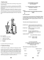
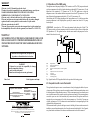
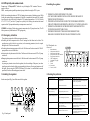
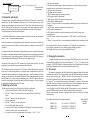
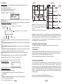
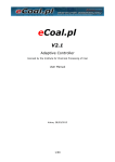
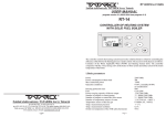
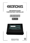
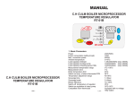
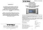
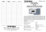
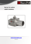
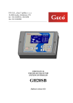
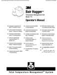
Admission date Realization date Signature RT09PID/2009/v.5.11 ANG Remarks Zakład elektroniczny TATAREK Jerzy Tatarek USER MANUAL RT-09/PID MICROPROCESSOR REGULATOR OF BOILER TEMPERATURE WITH THE FEEDER v 5.11 (12.05.2009 Software v5.11) Prog Man + Auto Start Stop - The regulator controls the CO system (Central Heating System) with the boiler equipped with the automatic fuel feeder, in which boiler temperature changes by altering the cycles of feeding the fuel . The applied algorithm PID enables the operation with an automatic modulation of boiler power. The generated heat suits what you need, thanks to that the combustion process is equal ( there're no sudden temperature changes in the combustion chamber and the chimney), more efficient and guarantees much longer existence and stability of the heating system. The regulator controls the operation of blower, circulating pump CO and loading pump CWU (warm applicable water). The regulator is equipped with the clock, which enables an automatic change of the settings at different times of the day. It can run with any room thermostat or remote control system of the TATAREK company. 1. Basic parameters Power supply Power consumption without load Max. connection power Operation condition Housing protection class Control output of the feeder Control output of the blower Control output of the circulating pump CO Control output of the loading pump CWU Fuse Safety thermostat of the boiler Safety thermostat of the feeder Temperature sensor of the boiler Temperature sensor of the container CWU Temp. measurement precision Temp. measurement resolution Number of the time zones 16 230V/50Hz 10W 1400W 5÷50 oC, humidity 10÷80% no condensation IP30 3A/230VAC 1A/230VAC continuous rotation regulation 1A/230VAC 1A/230VAC 2*6,3A/250V bimetallic 95 oC bimetallic 70 oC KTY81 (0...+100 oC) KTY81 (0...+100 oC) 2 oC 0,5 oC 4 1 2. Operation principle The coal boiler CO with the automatic fuel feeder runs the following cycle: firing-up, automatic operation and switching-off. In the firing-up phase the blower and the feeder are controlled manually (manual mode "Man"). Standardly the blower only operates and after reaching the stable embers you need to activate the automatic operation. After going over to the automatic phase the feeder makes the fuel feeding cycles whose frequency changes dependent on actual demand for heat. After burning out the fuel boiler temperature goes down. If the temperature lowers to the preset level the regulator turns off the blower and the feeder after the preset time. The automatics limits boiler temperature to 90 oC and at 95 oC switches off the boiler. CE CONFORMITY DECLARATION Ref. No. 57.RT.01.2007/1/B We, ZAKŁAD ELEKTRONICZNY TATAREK Jerzy Tatarek 75 Swieradowska St. , 50-559 Wroclaw declare under our sole responsibility that the product: MICROPROCESSOR REGULATOR OF BOILER TEMPERATURE WITH THE FEEDER model: RT-09, RT-09S, RT-09PID REG is in conformity with the basic requirements included in Directive EMC 2004/108/WE of 15.12.2004 (the electromagnetic compatibility - law gazette No 82 pos. 556 ) and Directive LVD 2006/95/WE of 12.12.06Directive of Economy Minister of 21.08.07 regarding the requirements for electric devices (Law Gazette No. 155 pos. 1089) To the conformity evaluation the following harmonized standards were used: STB T1 PN-EN 60730-2-1: 2002 - D1 T2 M S1 M REG STB T1 T2 D1 S1 Regulator RT-09 Safety temperature sensor of the boiler Temperature sensor of the boiler Safety temperature sensor of the feeder Blower motor Feeder motor PN-EN 60730-1: 2002 - Automatic electric regulators for house usage and the like. Part 2-1: Specific requirements regarding electric regulators for electric house devices Automatic electric regulators for house usage and the like. Part 1: General requirements. PN-EN 55022: 2000 - Electromagnetic compatibility (EMC)- IT devices Characteristics of radioelectric noises. Acceptable levels and measurement methods Complementary information: Laboratory IASE 51-618 Wroclaw, 1 Wystawowa st. Test report No. Fig. Signals from the RT09 connected with boiler operation 2.1 Operation of the CO pump 26/DL/I/07 of 23.04.2007 25/DL/I/07 of 23.04.2007 Electronic Engineering Plant TATAREK has initiated management system and complies with the following standard : ISO9001: 2000 CERTIFICATE No. 133/2004 of 01.2004 Polish Foreign Trade Chamber The last two digits of the year in which the CE marking was affixed: 07 An additional function of the regulator is controlling the CO circulating pump. If the boiler temperature exceeds the preset value the CO pump turns on. Turning off the pump below that value causes a faster heating of the boiler over the dew point and in effect extending the life time of the boiler. If the regulator cooperates with a room thermostat when room temperature is too high the pump runs cyclically (parameter No 41). The CO pump runs also cyclically if the PriorityCWU is set (parameter No 58) while feeding the CWU container. The regulator realizes the after-season rundown of the pump - the pump turns on for a minute if it doesn't run for a week. Place of issue: Manufacturer representative: Wroclaw Mirosław Zasępa Date of issue: Position: 17.09.2007 2 Designer 15 WARRANTY 2.2 Operation of the CWU pump 1.Warranty is valid [24] months from the date of sale. 2.Producer does not take responsibility for any mechanical damages made by user. 3.MAKING REPAIRS OR MODYFYING THE DEVICE BY USER IS FORBIDDEN AND CAUSES WARRANTY CANCELATION 4.Warranty card is valid only with date of sale, seller's signature and stamp 5.Warranty and after-warranty repairs should be done only by producer, damaged regulators should be sent to producer in order to make all repairs needed. 6.Warranty protection involves the EU 7.Warranty does not exclude, not restrict and not suspend buyer’s rights coming from the incompatibility of the article with the agreement (Laws Journal No. 141 Pos. 1176) WARNING ! The regulator controls the pump feeding the CWU container as well. The CWU pump can be turned on if water temperature in the boiler is higher than the preset threshold 45oC (parameter no. 51) and higher than in the container by 3oC (parameter no. 52). The CWU pump turns on when the temperature sensor of the container indicates temperature lower than 50oC (parameter no. 53) and turns off when it indicates temperature higher by 10oC, so 60oC (parameter no. 54). After finishing the CWU feeding the pump runs for 1min (parameter no. 56), which prevents from increasing temperature in the fireplacejacket, especially in summer time when the C.O. pump doesn't operate. ATTENTION! - in case there's no CWU sensor the container feeding takes place "in dark". The CWU pump switches on if water temperature in the boiler reaches the preset value or is higher than 50oC (parametr no. 53). The regulator realizes the after-season rundown, the pump turns on for a minute if it doesn't run for a week. ZS ANY MODIFICATION OF THE REGULATOR MADE BY USER CAN BE THE CAUSE OF SAFETY CONDITIONS DETERIORATION AND CAN EXPOSE THE USER TO ELECTRIC SHOCK OR DAMAGE DEVICES SUPPLIED. TP TPG REG T3 CWU P2 P1 Connection cable of regulator may be replaced only by producer or his authorized service locations WARNING! 1. Producer does not take the responsibility for damage caused by atmospheric discharge 2. and overvoltage in the mains 3. Burnt fuses are not subject to warranty replacement Date of sale Seller's signature and stamp OG1 K REG ZS TP TPG K T3 P2 OG1 P1 Regulator RT-09 Remote programmer RT-09 Room thermostat Sensor of external temperature (for a weather regulator) Boiler Temperature sensor of the CWU container CWU pump Central Heating CO circulating CO pump Fig. Signals from the RT-09 regulator linked to the operation of the heating system 2.3 Cooperation with a room thermostat ARGO-FILM Recycling Plant No. 6 180 Krakowska st., 52-015 Wroclaw Worn out electronic and electric devices must be transfered to ph.: 071 794 43 01, 0 515 122 142 the utilization collection place, where will be accepted for free Register No.. GIOS: E 0002240WZ Zakład elektroniczny TATAREK Jerzy Tatarek 50-559 Wroclaw, 75 Swieradowska st ph. (071) 367-21-67, 373-14-88, fax 373-14-58; tax index number 899-020-21-48; Bank account : BZ WBK S.A. O/WROCŁAW 6910901522-0000-0000-5201-9335 www.tatarek.com.pl.; E-mail: [email protected] 14 The regulator has the input to connect a room thermostat of any kind equipped with the relay nonvoltage output. To the regulator you need to connect the terminals of the thermostat that short-circuit if room temperature is higher than the preset one. Till the room temperature is lower than the preset one set in the thermostat (relay contacts open) the regulator runs normally. If the room temperature exceeds the preset one set in the thermostat (relay contacts shorted) the regulator modifies its operation: the preset temperature of the boiler lowers(parameter no. 14) and the CO pump runs cyclically (parameter no. 41). If the thermostat is not mounted then the corresponding input of the regulator must be left unconnected. The thermostat should be placed in the largest room of a building. In that room there must not be installed any near-radiator thermostatic valves. It must be mounted at the height of 1,5m off ground, away from windows and heaters. In the other rooms the thermostatic valves can be mounted. 3 2.4 CWU priority and summer mode 4 Installing the regulator Parameter no. 58 "PriorytetCWU” defines the way of feeding the CWU container. There are modes as follows: WYŁ - normal operation (parallel operation of pumps) without favouring the CWU system 1 2 3 CZUJN PODA IK POMPA CWU 1A/230VAC POMPA CO 1A/230VAC DMUCHAWA 1A/230VAC PODAJNIK 3A/230VAC KA JN I T E RM O REGULATOR TEMPERATURY KOT£A C.O. AT PO K ST Typ: RT-09 Nr................. ZPIEC BE C ZU WE: 230 VAC 6A 1380VA IK KO JN A T£ JNIK ZU WU 4 ÑSTW NIK C UJ 5 6 7 8 9 10 11 8. Solving the problems Problem Regulator doesn't run On the control panel (Fig.1) are all the controls of the regulator 1 Connection of: 1. Room thermostat 2. Safety sensor of the boiler 3. Safety sensor of the feeder 4. Temp. sensor of the CWU container 5. Temp. sensor of the boiler 6. CWU feeding pump 7. Circulating C.O. pump 8. Blower 9. Feeder 10. Power cable 11. Fuses 6,3A/230V ZE 3. Handling the regulator Fig.2 Back panel view OWY OJ regulator turns on the feeder for a preset time (see the mounting parameters) in order to push through the fuel. The blower is turned off. Exceeding the maximum temperature of the boiler. The blower and feeder are turned off. The CO pump switches on to cool off the boiler. Activating the safety thermostat of the boiler. The blower and feeder are turned off. The CO pump switches on. Damaging the temperature sensor of the boiler. The blower and feeder are turned off. The CO pump switches on. Any emergency situation is stored in the regulator (also after switching off the power), an alarm signal is generated, and on the display a corresponding info shows up. Pressing any button turns off the signal. After pressing the START/STOP button (10) the alarm is cancelled and the normal operation (if the cause of alarm disappears) comes back. CZ 2.5 Emergency situations The regulator recognizes the following emergency situations: Exceeding the feeder temperature as an effect of moving back the flame into the feeder. The C SUMMER - switching off the heating system in summer time (the CO pump doesn't run). The CO boiler operates only in the function of CWU getting ready ! THE REGULATOR IS SUPPLIED BY 230V/50HZ . ANY MOVES REGARDING INSTALLATION SHOULD BE MADE AT THE DISCONNECTED MAINS. ! THE REGULATOR HAS TO BE CONNECTED TO THE MAINS WITH THE ZERO-PIN THROUGH A DIFFERENTIAL DEVICE ACC. TO THE VALID LAWS ! THE REGULATOR SHOULD NOT BE EXPOSED TO WATER AFFECTING. ITS ENVIRONS OUGHT TO BE CLEAN. ! THE PRODUCER DOESN'T TAKE ANY RESPONSIBILITY FOR DAMAGES CAUSED BY WRONG USAGE OF THE REGULATOR. A ZAŁ - faster reaching the readiness of CWU by limiting a heat reception of the heating system. While feeding the container the preset temperature of the boiler is automatically increased (if it's actually lower) up to the value of effectively feeding the CWU container [parameter no. 53)+54)+52) that is 0oC+10oC+3oC=63oC] and the CO pump runs cyclically. After feeding the container the normal operation of the CO pump and the actual preset temperature comes back. ATTENTION! 2 3 4 5 6 5a Man Prog Start Stop Auto 9a 8 7 6a + - 9b 9 10 11 Possible cause 1.Wrong connection of the power cable 2.Damaged fuse Solution 1.Check power connection 2.Check the fuses, replace the damaged onebe aware of its parameters 3.Switch SIEC turned off 3.Switch the SIEC button to the I position On the emergency screen the text "CZUJNIK TEMP. KOTŁA" shows up. 1.Disconnected temperature sensor 1.Check a sensor connection 2.Damaged temperature sensor 2.Go to the service Regulator doesn't control the boiler, emergency screen 1.Emergency memory is not deleted 2.Cause of emergency still exists CWU pump doesn't run CO pump doesn't run 1.Damaged temp. CWU sensor. 2.Too little difference between boiler and CWU temperatures 3.CWU system blocked 1.Boiler temperature too low 2.Summer mode is turned on Fig.1 Control panel 4 13 1.Press START/STOP to delete the emergency memory 2. Wait till the cause stops (e.g. the feeder cools off) 1.Check a sensor connection 2. Increase the preset temperature of the boiler 3. Turn on the CWU system by setting the parameter no. 50 1.Wait till the boiler temperature exceeds the value of the parameter no. 40 2. Turn off the summer mode by changing the parameter no. 54 Screen of the manual mode MANUAL DMUCHAWA* 72.0 O PODAJNIK Indicator „*” means switching on a device DMUCHAWA=BLOWER PODAJNIK=FEEDER Boiler temperature 5.3 Automatic mode (Auto) The automatic mode is indicated by lighting up the LED on the AUTO button (9). In this state the regulator keeps the boiler temperature at the preset level. The feeder makes the cycles whose frequency alters depending on the current need for heat. They're the so-called operation cycles (the LED (9a) lights up)After exceeding the preset temperature the regulator realizes the so-called keeping-up cycles the aim of which is to keep up the combustion process (the LED (9b) lights up). The preset temperature of the boiler can be changed by: * a user. With the PROG button you need to set the screen of the boiler operation and then with the buttons "+" and "-" you change the main temperature. *a time zone mechanism. At the programmed times the temperature is increased or decreased by the value of the current correction coefficient of the current time zone. During this correction the LED (2) lights up. *a room thermostat. If the room temperature is higher than the preset one set on the room thermostat the regulator sets minimum temperature of the boiler operation, which corresponds to the transition to the keeping-up cycles of the combustion process. This state is signalled by the LED (2) (change of the preset temperature) and blinking the LED (9b) (enforced keeping-up cycles) *the regulator if the feeding of the CWU container in the priority mode takes place. The boiler temperature is increased to the value of guaranteeing an efficient feeding. If for 2 hours from the time of passing to the AUTO state, the boiler temperature doesn't reach the preset one or for 45min the temperature is lower than the switch-off temperature of the boiler, the regulator stops the feeder and the blower, passing to the stop state. From the automatic mode to the stop state you can transition by pressing the STOP button (10) and to the manual mode by pressing the MAN button (6). In order to avoid an accidental going out of the AUTO mode the button are needed to be pressed longer. If during the automatic mode the power supply is off, after its restoring the regulator returns automatically to the AUTO mode. 6. Switching on the boiler The following points show the way the heating up of the boiler is undertaken: You press the MAN button (6) till the yellow LED (6a) lights up With the "-" button (11) you switch on the feeder and wait till the fuel finds in the hearth With the "-" button (11) you turn off the feeder You heat up the hearth With the "+" button (7) you turn on the blower You wait till the stable embers comes up You press the AUTO button (9) till the green LED lights up. The regulator takes control of the blower and the feeder in the automatic mode You can also correct the preset temperature with the buttons "+" and "-" (7) (11). 12 1. LED signals an emergency 2. LED signals an automatic change of the preset temperature as an effect of the active time zone or cooperation with a room thermostat or remote control system 3. LED signals the feeder operation 4. LED signals the blower operation 5. "PROG" button programming / choosing a parameter 5a. LED signals the mode of programming 6. "MAN" button - change of the operation to the manual one 6a. LED signals the manual operation 7. Button "+" increases the value of a chosen parameter/controlling the blower in the manual mode 8. Text display 9. "AUTO" button - change of the operation to the automatic one 9a. LED signals the automatic mode 9b. LED signals the automatic mode with a minimum power of the boiler (keeping up the combustion process) 10. "START" button - confirms a chosen parameter or "STOP" button - turns off the automatic mode 11. Button "-" decreases the value of a chosen parameter/controlling the feeder in the manual mode The regulator condition is shown on the text display (8). The displayed screens inform about device operation, temperature of sensors, enables parameter changing and the like. The changing of the screens is done by pressing the PROG button (5). 3.1 Changing the parameters Changing the parameters is done by pressing the START/STOP button (10). As a result the parameter field starts blinking. That value can be changed by "+" (7) or "-"(11) butons. Another pressing the START/STOP button (10) confirms the changes - the field stops blinking. The changed parameter not confirmed for 60secs is not stored and the former value is valid. 3.2 Time zones The regulator is equipped with the clock, which enables an automatic change of the operation at different times of the day. The day is divided into 3 zones ($1, $2, $3) and the time span in which there's no active time zone that is STREFA 0 or BAZA. The zone is defined by the start time (OD)/(from), finish time (DO)/(till) and correction of the preset temperature (TEMP). E.g. setting -5 oC over a night means lowering the temperature by 5 degrees to the preset main temperature. That way of setting causes that there's no need for reprogramming all the zones at changing weather conditions. It only requires controlling the main temperature. A zone, for which the start (OD) equalling the end (DO) temperature is set or the temperature 0correction (TEMP)is defined, is inactive, and don't change the settings of the regulator. The time zones can overlap each other, in that situation the settings for an active zone of higher number are valid. In the regulator the factory default settings are as follows STREFA 1 ($1) STREFA 2 ($2) STREFA 3 ($3) OD 6.30 DO 8.00 TEMP 0 oC OD 14.00 DO 17.30 TEMP 0 oC OD 20.00 DO 6.00 TEMP 0 oC 5 STREFA1=ZONE1 OD=FROM DO=TILL 3.3 Screens FEEDER BLOWER Emergency screens are not available until one of the following emergency situations occurs: * Exceeding the feeder temperature *Exceeding the maximum temperature of the boiler *Activating the safety thermostat of the boiler *Damaging the temperature sensor of the boiler FEEDER parameter no. 33=1 BLOWER ALARM!! CZUJNIK TEMP KOTŁA Emergency situation is accompanied by a broken sound signal that can be cancelled by the START/STOP button. Operation screen of the boiler shows the actual temperature of the boiler, preset temperature, blower power, current time and number of time zones. Preset temperature calculated by the regulator Current temperature of the boiler o 74.5 17:43 $1 current time No. of time zone o 74 [74] 50% - [] Main temperature set by a user - in the brackets Blower rotation ! Preset temperature (calculated by the regulator) can be other than the main temperature (set by a user) in case of: - limiting the maximum temperature of the boiler - preset temperature cannot exceed the parameter 10 (90 oC) - limiting the minimum temperature of the boiler - preset temperature cannot exceed the parameter o 11 (50 C) - feeding the CWU container in the priority mode - preset temperature (if it's lower) is increased up to the value of guaranteeing an efficient feeding / parameter 52+ no.53+no.54(63 oC) -room thermostat is active - preset temperature is decreased to the value of the parameter no. 41 (50 oC) -remote control system is active - temperature is set by the remote control system RT09ZS -time zone is active - temperature correction for a given time zone is valid. It's a stable screen that is in order to change it you need to press PROG. Boiler operation screen TEMP 74 KOTŁA It's a stable screen that is in order to change it you need to press PROG System operation screen On the screen you find the symbols of devices: CWU- warm applicable water container (CWU! means the CWU priority is set. CO- central heating K- boiler The blinking arrows indicate the current flow of heat as a result of pumps operations: K->CWU - feeding CWU pump is turned on K->CO - circulating CO pump is turned on 6 FEEDER parameter no. 33=2 Attention: if the current break time of the feeder is shorter than the time of extending the blower operation time 23), the blower doesn't go down to the lower rotation 22). (that situation is marked by the dotted lines in the figures. FEEDER parameter no. 33=0 Attention: In the keeping-up cycles of the combustion process (that is if the boiler operates with minimum power)the blower is turned off when the feeder doesn't work (parameter no. 22 takes 0 value) and the parameter no. 33 defines if the feeder turns on every time (parameter no. 33=1 in every cycle; parameter no.33=2 every second cycle etc..) The value parameter no. 33=0 means taht in the keeping-up cycles only the blower turns on. 5. Operation states of the regulator The regulator can be in the stop , manual or automatic state. In every case the emergency situations is controlled. 5.1 Stop state In this state the LED on the MAN button (6) doesn't light, nor does the AUTO one (9). It's a state in which the blower and the feeder are turned off. A user can browse and change the parameters. The pass to the manual state follows if the MAN button (6) is pressed The pass to the automatic state follows if the AUTO button (9) is pressed. 5.2 Manual operation(Man) The manual operation state is indicated by lighting up the LED on the MAN button (6a). At first the blower and the feeder are turned off. A user can switch on the blower with the "+" button (7) and the feeder with the "-" button (11). Yet another pressing the buttons turns off the blower/feeder. The state of the devices and the current temperature of the boiler is indicated by the LEDs (3) and (4) and the display (8). The manual mode doesn't affect the CO and CWU pumps, which operate acc. to their settings. The manual mode enables testing the feeder and the blower, heating up the boiler and releasing the feeder. The pass to the stop state follows if the PROG button (5) is pressed The pass to the automatic state follows if the AUTO button (9) is pressed. 11 SETUP PARAMETERS No Description Range 33 Cycles of the feeder 0...10 34 Control of the feeder temperature Emergency pushing out of the fuel 35 40 41 50 51 52 53 54 Temperature of the switch-on of the CO pump Temperature of the switch-off of the CO pump CWU container Temperature of the switch-on of the CWU pump Delta CWU Minimum temp. of CWU Max dTemp of CWU 55 Factory Setting setting 1 Switching off this function removes the control of the feeder temperature 1...300s 10s Switch-on time of the feeder to push out the embers fuel during the emergency of exceeding the feeder temperature 40...60 oC 42 oC Minimum temp. of the boiler at which the CO pumps switches on. 1...30min 4min Break time of the CO pump in case if the room thermostat decides of turning off the heating. After the time the pump turns on for 30s Value WYŁ./OFF blocks feeding the CWU container WYŁ/OFF ZAŁ/ON ZAŁ/ON 20...80 oC 45 oC 1...10 oC 3 oC 30..100 oC 50 oC 2..15 oC 10 oC 0..10min 1min CWU priority WYŁ/OFF WYŁ/OFF PRIO 99 999 SUMMER WYŁ/OFF WYŁ/OFF ZAŁ/ON Factory settings WYŁ/OFF WYŁ/OFF ZAŁ/ON (Presets) Diagnostics ! means setting the CWU priority In the keeping-up cycles (see the next figure) the feeder doesn't need to turn on every time. This parameter defines what times the feeder turns on: 1- feeder turns on in every cycle, 2-every second cycle, etc..The value 0 means during the keeping-up cycles only the blower is turned on. WYŁ/OFF ZAŁ/ON ZAŁ/ON Rundown time of the CWU pump 58 FUNCTION Minimum temp. of the boiler at which the CWU pump switches on. Minimum temperature difference of the boiler and the CWU container needed for the CWU pump to run Minimum temperature of the CWU container. Below the temperature the feeding pump turns on. Maximum temperature of the CWU container is the parameter 53)+54). Above the temperature the feeding pump turns off Rundown time of the CWU pump. Extending the pump operation after the end of feeding the CWU container. It prevents from a sudden temperature increase in the boiler after the end of feeding, especially in summer time when the CO pump doesn't run. Normal operation (parallel work of the pumps) without favouring the CWU circuit. Turning on this function causes that during the feeding of the CWU container the heat reception by the CO system is limited through the cyclic operation of the CO pump ( the same as with a room thermostat turning on). Besides during the feeding the boiler temperature is o increased (if it is lower) to 63 C (parameter no. 52+53+54) Summer mode. Only feeding the CWU container Value ZAŁ/ON causes adding the diagnostics screen for the service It's not a parameter only the way for setting the parameters to the factory defaults. In order to set the factory default you need to set to ZAŁ/ON and then confirm with the START button. Screen for the activated summer mode (only CWU) It's a stable screen that is in order to change it you need to press PROG. Screen of the clock ZEGAR $1 17:15 The screen shows the current time and number of a valid time zone. Time correction is possible after pressing START/STOP (10). As a result the minute field starts blinking. The blinking value you can change with the "+" (7) or "-" (11) buttons. Pressing the PROG button (5) you go over to the hour field (you can change it as described above with "+/-"). Pressing START/STOP (10) confirms the changes (the clock field stops blinking). Screen of setting the parameters PoziomUstawiania 0 4. Adjusting the regulator to the boiler For a proper operation of the regulator the following parameters must be determined: Combustion conditions of the single portion of the fuel, that is the time of the feeder operation-parameter no. 30, blow force during the feeder operation 21) and time of extending the blower operation 23) Shortest break time of the feeder in which there's full combustion of the feeded fuel 31) (time guaranteeing 100% power of the boiler). Longest break time of the feeder that won't cause going out the boiler 32) (time guaranteeing the keeping-up of the combustion process. Maximum air blow force 22) while the feeder doesn't run- the blow corresponding to the max power of the boiler Minimum air blow force 22a) while the feeder doesn't run- the blow corresponding to the minimum power of the boiler 10 Normally the setting level is "0" which means the parameters are not available. After switching to the level 1 or 2 the following screens show the values of the parameters. The level 1 shows the most commonly used parameters, level 2 - time zones. The last screen contains the text ,,**koniec**" after which the comeback to the former screens takes place. 7 LEVEL 1 – BASIC No DESCRIPTION RANGE 21 Blower rotation during feeder operation Turning on the feeder Time of turning off the pump 3...100% 100% Blower rotation (if in the setup the continuous operation of the blower was set)if the feeder works. 1...600s 25s Time of turning on the feeder 1...30min 4min 30..100 oC 50 oC 0..10min 1min Break time of the CO pump in case if a room thermostat decides of switching off the heating. After that time the pump turns on for 30s. Minimum temperature of the CWU container. Below the temperature the feeding pump turns on. Rundown time of the CWU pump. Extending the operation time of the pump after finishing the CWU feeding. It protects against a sudden temperature increase in the boiler after finishing the feeding, especially in summer time when the CO pump doesn't run. Turning on the function causes that during feeding the CWU container the heat reception by the CO system is limited by a cyclic operation of the CO pump (the same like at turning on a room thermostat. Summer mode. Feeding the CWU container only. 30 41 53 Minimum temp. of CWU 55 FACTORY SETTING Rundown time of the CWU pump 58 CWU Priority OFF ON FUNCTION SETTING OFF SUMMER LEVEL 2 – TIME ZONES No DESCRIPTION RANGE $11 $12 $13 $21 $22 $23 $31 $32 $33 Zone $1 from Zone $1 till Zone $1 temp Zone $2 from Zone $2 till Zone$2 temp Zone $3 from Zone $3 till Zone $3 temp 0:00...23:45 0:00...23:45 -20...+20 oC 0:00...23:45 0:00...23:45 -20...+20 oC 0:00...23:45 0:00...23:45 -20...+20 oC FACTORY SETTING SETTING FUNCTION !SETUP PARAMETERS ALSO INCLUDE ALL THE MENTIONED PARAMETERS EXCEPT FOR THE INFORMATION ABOUT THE TIME ZONES. In order to activate the screen of setting the setup parameters you need first to press the PROG button (5) at the power off and then switch on the power. After appearing the text "KONFIGURACJA?" you need to release the PROG button and then press the START button (10). From now on the following screens show the values of the setup parameters which can be altered according to the before mentioned rules. The last screen includes the text "**koniec**" after which the normal operation is restored. SETUP PARAMETERS No DESCRIPTION 10 RANGE 50...90 oC 90 oC 25...55 oC 50 oC 20...40 oC 35oC Start time of the time zone 1 End time of the time zone 1 Temp. correction of the zone 1 Start time of the time zone 2 End time of the time zone 2 Temp. correction of the zone 2 Start time of the time zone 3 End time of the time zone 3 Temp. correction of the zone 3 0,5..5,0 oC 1,0oC 25...85 oC 50oC Demonstration of the 53 parameter changing "Temp. min CWU" defining water temperature in the CWU container (parameter level 1). Press as follows: * repeatedly "PROG" untill the parameter settings screen appears " Level of setting 0" *"START" -> blinking 0 *"+" -->blinking 1 * START -->1 stops blinking (the level 1 was chosen) *repeatedly "PROG" till the 53 parameter screen shows up "Temp.min CWU" *START -->the current value you want to change starts blinking * "+.-" --> you set a new value * START --> confirming the new value *repeatedly untill the boiler operation screen shows up Screen of setting the setup parameters ! SETUP PARAMETERS ADJUST THE REGULATOR TO THE PROPERTIES OF THE BOILER AND THE CO SYSTEM. THEIR MODIFICATION SHOULD BE CONSULTED WITH THE BOILER PRODUCER AND DESIGNER OF THE CO SYSTEM. ILL-CONSIDERED CHANGES OF THE PARAMETERS CAN CAUSE AN UNSTABLE AND INEFFICIENT OPERATION OF THE SYSTEM 8 Maximum preset temperature of the boiler ( if the settings of the time zones or room thermostat cause exceeding that value then they're restricted to that value) Maximum setting of temp 11 Minimum setting of temp 12 Stop of the boiler NA 6:30 8:00 0 oC 14:00 17:30 0 oC 20:00 6:00 0 oC FUNCTION FACTORY SETTING SETTING 13 Hysteresis 14 Temperature of room thermostat 15 PID 20 Blower control OFF/WYŁ ON/ZAŁ ON/ZAŁ Continuous Continuous Continuous1 Płynne on/off 21 100% Blower rotation 3...100% during feeder operation Max rotation 22 3...100% 50% of the blower at the pause of the feeder 22a Minimum rotation 3...100% 30% of the blower at the pause of the feeder 23 1...600sek 30sek Switch-on of the blower 30 1...600sek 25sek Switch-on of the feeder 31 Minimum switch-off 1...1200sek 35sek of the feeder (20min) Maximum switch-off 100…1200 600sek 32 of the feeder sek (20min) Minimum preset temperature of the boiler ( if the settings of the time zones or room thermostat cause exceeding that value then they're restricted to that value) Temperature below which the switch-off of the boiler takes place in the automatic operation mode (that is a stop state). The switching off takes place if the temperature for 45min doesn't increase Temperature difference of passing between an operation state and keeping up the combustion process while the PID algorithm is not active. Preset temperature of the boiler at the cooperation with a room thermostat. That is the temperature to which the regulator is set in case if the room thermostat decides about turning off the heating. ATTENTION: this parameter should be greater than the switch-off temperature of the boiler. WYŁ blocks the PID algorithm. The boiler works without power modulation. That is with the max power if the temperature is below the preset one, and then goes to the keeping-up state. Adjusting the blower control to the type of a motor (option "Continous1"/"Płynne1" concerns the motor class RV 14) Blower rotation during the feeder operation (if in the setup the continuous run of the blower was set)(see the next figure) Max rotation of the blower when the feeder doesn't operate (see the next figure) - Minimum rotation of the blower when the feeder doesn't operate (see the next figure) Time of extending the blower operation at the moment when the feeder is turned off (see the next figure) Time of switching on the feeder (see the next figure) Shortest switch-off time of the feeder - it guarantees reaching 100% power of the boiler (see the next figure) Longest switch-off time of the feeder - it guarantees keeping up the combustion process (see the next figure) 9