1
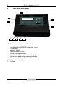
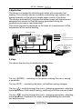
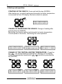
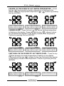
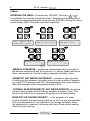
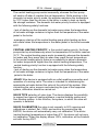
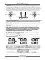
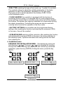
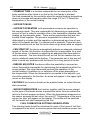
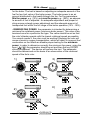
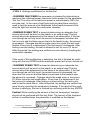
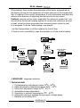
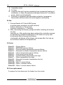
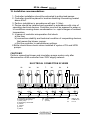
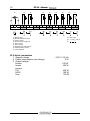
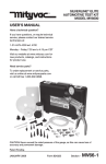
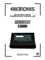
MICROPROCESSOR
TEMPERATURE CONTROLLER
24l+
SERVICE MANUAL
WARRANTY CARD
2
SP 24 + Manual
1.
Front panel description
10
2
1
3
4
5
6
7
8
9
Controller view with marked functions
1.
2.
3.
4.
5.
6.
7.
8.
9.
10.
Turning on (hold ENTER button for 2 sec.).
LCD display.
Indicator lights.
Device control buttons.
Airflow start up indicator.
Central heating pump start up indicator.
Hot service water pump start up indicator.
Floor pump start up indicator.
Loader start up indicator.
7A fuse.
3
SP 24 + Manual
2.Application
The device is intended for controlling the boiler with automatic fuel
feeding. The controller has an innovative controlling Logic system, the
system operates on the basis of steady power control in the boiler.
The devices automatically changes the airflow power and dispenses an
adequate fuel amount so that the energy generated during the
combustion process is used maximally.
The control process is performed on the basis of a measurement of the
temperature of the central heating.
INDOOR ADJUSTER
CONTROLLER
BOILER
Cold water
CENTRAL HEATING INSTALLATION
VALVE
SENSOR
Hot water
DOMESTIC
HOT
WATER
SENSOR
Supplying electric circuits
Controlling electric circuits
PUMP
BOILER SENSOR
MIXING
VALVE
Thermostatic temperature limiter
PUMP
PUMP
RETURN SENSOR
ADDITIONAL
SHORT CYCLE
PUMP
FLOOR
INSTALLATION
SYSTEM
SENSOR
3. Keys.
The device has four keys intended for its operation:
The key (ENTER) – switching on the device, entering the menu, saving
a parameter.
The key (EXIT) – monitoring the boiler, exit without saving changes.
The key ( ), scrolling through the menu, changing parameters, adjusting
the temperature of the central heating, switching on/off the summer mode.
The key ( ), scrolling through the menu, changing parameters, adjusting
the temperature of domestic hot water, enabling/disabling the domestic
hot water function.
4
SP 24 + Manual
4.Start-up and operation.
STARTING UP THE DEVICE- Press and hold the key (ENTER).
After starting up, a central heating and domestic hot water temperature
is screened on the LCD display, the device starts to operate.
3 sec
0
0
CH
20 C z 55 C
0
0
HSV 20 C z 45 C
CHANGE OF MONITORING THE BOILER- Change of reading after
pressing the key (ENTER).
Monitoring the central heating and domestic hot water temperature,
Current power in the boiler, monitoring the valve operation.
0
0
CH
20 C z 55 C
0
0
HSV 20 C z 45 C
0
20 C
BLOWER POW. 50%
Zw1
550C z 550C
AIR T 500C
75%
CHANGE OF THE CENTRAL HEATING TEMPERATURE.- Press the
key ( ) , the central heating temperature is flashing on the display,
Select the appropriate temperature,( ) ( ) confirm by pressing the
key (ENTER)
0
0
CH
20 C z 55 C
0
0
HSV 20 C z 45 C
0
0
CH
20 C z 50 C
0
0
HSV 20 C z 45 C
0
0
CH
20 C z 50 C
0
0
HSV 20 C z 45 C
5
SP 24 + Manual
CHANGE OF THE DOMESTIC HOT WATER TEMPERATURE – Press
the key ( ),the domestic hot water temperature is flashing on the
display. Select the appropriate temperature,( ) ( )confirm by pressing
the key (ENTER)
0
0
CH
20 C z 55 C
0
0
HSV 20 C z 45 C
0
0
CH
20 C z 55 C
0
0
HSV 20 C z 50 C
0
0
CH
20 C z 55 C
0
0
HSV 20 C z 50 C
SUMMER MODE - Press the key ( ),the central heating temperature
is flashing on the display. Press and hold the key ( ), release it when
two horizontal lines appear on the display instead of the temperature.
Confirm by pressing the key (ENTER)
0
0
CH
20 C z 55 C
0
0
HSV 20 C z 45 C
0
0
CH
20 C z -- C
0
0
HSV 20 C z 45 C
0
0
CH
20 C z -- C
0
0
HSV 20 C z 45 C
SWITCHING ON THE DOMESTIC HOT WATER PUMP. - Press the key
( ),the domestic hot water temperature is flashing on the display.
Press and hold the key ( ), release it when two horizontal lines appear
on the display instead of the temperature. Confirm by pressing the key
(ENTER)
0
0
CH
20 C z 55 C
0
0
HSV 20 C z 45 C
0
0
CH
20 C z 55 C
0
0
HSV 20 C z -- C
CH
0
0
20 C z -- C
6
SP 24 + Manual
5.Menu
ENTERING THE MENU - Press the key (ENTER). The keys ( ) ( )
are intended for scrolling through the menu. Entering next sub-menu and
confirming a selected parameter, press the key (ENTER). Exiting the menu,
press the key (EXIT) Domestic hot water hysteresis.
0
0
CH
20 C z 55 C
0
0
HSV 20 C z 45 C
Manual operation
HSW hysteresis
HSW hysteresis
HSW hysteresis
1 0c
5 0c
-MANUAL OPERATION – enables an independent start-up of each of
the devices cooperating with the controller, i.e. airflow, feeder and three
temp. measurements (central heating, domestic hot water, floor)
-DOMESTIC HOT WATER HYSTERESIS – enables to adjust a delay
of starting up the domestic hot water pump by a set number of degrees,
e.g. while 2ºC hysteresis and 50ºC set temperature, the pump starts up,
when the domestic water temperature drops to 48ºC.
-CENTRAL HEATING/DOMESTIC HOT WATER PRIORITY- the device
controls three pumps (central heating, domestic hot water, floor). The
function lets determine a sequence of starting up individual pumps.
DOMESTIC HOT WATER PRIORITY – in the domestic hot water
priority, domestic hot water pump starts up as the first one and operates
until a set temperature is not reached in the storage container. When
the temperature is reached, the pump switches off and central heating
and floor pump start up.
SP 24 + Manual
7
The central heating pump works incessantly, whereas the floor pump
will switch off when it reaches the set temperature. While working in the
domestic hot water priority mode, the adjuster maintains the temperature
by 10ºC higher than the set one in the boiler in order to heat up rapidly
the storage container. The domestic hot water priority function is equipped
with the following safety functions:
- lack of starting up the domestic hot water pump when the temperature
of hot water storage container is higher than the temperature of the water
jacket in the boiler.
-emergency start-up of the central heating pump while heating up domestic water when the temperature in the water jacket in the boiler exceeds
82ºC.
CENTRAL HEATING PRIORITY- in the central heating priority, the three
pumps start up simultaneously when the temperature in the boiler reaches
35 ºC. The central heating pump works incessantly, whereas the domestic
hot water and floor pump start up when they reach the set temperature.
In the central heating priority there is no possibility to adjust a domestic
hot water temperature higher than the central heating temperature. The
central heating priority function is equipped with the following safety
function:
- lack of starting up the domestic hot water pump when the temperature
of hot water storage container is higher than the temperature of the water
jacket in the boiler.
-VALVE 1 the device is equipped with an outlet enabling connection and
operation of a mixing valve. The valve is intended for maintaining the
appropriate set water behind the valve at the outlet of the system. After
connecting the valve, sensors and selecting the type of the supported
system, calibration should be carried out.
VALVE TYPE selection of valve type. The device displays the possibility
to support two types of heating systems; a central heating system and
floor heating system. In this function, the system, in which the valve will
operate, is selected.
VALVE CALIBRATION the valve is set manually to 50% opening and
calibrations is started. Set <YES> and confirm by pressing the key
ENTER, the device will automatically carry out calibration. If the boiler
(central heating) temperature is higher than 5ºC, the device will not carry
out calibration. When the display shows 100%, calibration will be finished,
exit with the key EXIT.
8
SP 24 + Manual
CAUTION attention should be paid to a operation direction of the valve.
At first stage of calibration, the valve should be set to 100% flow for the i
nstallation system, if otherwise and the valve is set to 0% flow, calibration
should be interrupted and the operation direction of the valve should be
changed by switching the cables on the mounting bar of the controller.
Bad
RETURN
SUPPLY
RETURN
SUPPLY
L1 N L1
L1 N L1
Mixing valve
Mixing valve
OK
RETURN TEMPERATURE the function protects the boiler from premature
corrosion maintaining the appropriate temperature water return from the
system. The recommended return temperature is determined by a boiler
manufacturer,
CAUTION maintaining the return temperature is superior (priority)
after enabling the function, the central heating temperature should be
modified. The temperature is set by minimum 10ºC higher than the set
return temperature. The lack of a modification of the central heating
temperature will cause a heat deficiency in the system.
TO SWITCH ON THE MIXING VALVE – Enter the monitoring of the
valve, press the key (ENTER).
Next, using the keys ( )( ) set a temperature behind the valve and
press the key (ENTER).
Zw1
200C z ---0C
AIR T 300C
50%
Zw1
200C z 400C
AIR T 300C
50%
Current temperature behind the valve
Zw1
200C z 400C
AIR T 300C
50%
Set temperature
0
0
Zw1
200C z 40 0C
AIR
T 30
3000C
C
50%
T
POW
50
%
Current return temperature
Percent coefficient of
valve opening
SP 24 + Manual
9
-FUEL TYPE switching the type of fuel used, e.g.: 1) pallet, 2) coal dust.
The controller allows to adjust the suitable parameters of the boiler
operation for each fuel separately, depending on the type used.
The types of fuel is earlier adjusted in the function FUEL 1/2/3/4
in the installation menu.
- FLOOR HEATING the controller is equipped with the function of
controlling the floor pump. It is equipped with an output supplying the
pump and floor sensor that is mounted on the return of the floor installation system.The system also requires installation of a thermostat limiting
the supply temperature. Controlling the pump can also be used with
a mixing valve mounted for operation in the floor mode.
- FACTORY SETTINGS the controller has the programmed factory
settings, after enabling the function and selecting the commend (YES)
in the menu, they will be recalled.
- OPERATION END switching off the controller, after enabling the function
and selecting the commend (YES) in the menu, the device switches to
the stand-by mode, it protects the boiler from boiling and the fuel tank
from catching fire.
6. Installation menu
ENTERING THE INSTALLATION MENU – Simultaneously press and
hold the keys ( )( ).The keys ( ) ( ) are intended for scrolling
through the menu. Entering next sub-menu and confirming a selected
parameter, press the key (ENTER). Exiting the menu, press the key
(EXIT)
0
0
CH
20 C z 55 C
0
0
HSV 20 C z 45 C
STAND-BY TIME
STAND-BY TIME
40 min
STAND-BY TIME
60 min
10
SP 24 + Manual
- STAND-BY TIME is a function responsible for an interruption of the
boiler operation when there is no fuel or the fuel feeder is blocked.
Set time measured by the controller when the central heating temperature
does not increase and remains within the range 0ºC to 5 ºC below the
temperature in the central heating
- SUPPORT PAUSE
- SUPPORT OPERATION both parameters concerns an operation in
the summer mode. They are responsible for dispensing an appropriate
amount of fuel in order to maintain a fire in the combustion chamber after
heating up the domestic water. There are two parameters that are inextricably linked together. The pause is responsible for a break that is
determined in minutes and the operation is determined as a time of operation of the feeder and fan. It is determined in seconds. These two parameters should be set so that the boiler does not go dead while on support.
- FAN START-UP the device automatically adjusts an adequate rotational
speed of the fan, the function of airflow start-up is responsible for a start
of the fan alone, it is based on adjusting an adequate start time determined in seconds. The time should be set so that the fan reaches the maximum rotational speed while starting. The parameter set in this way will
allow to avoid any problems with the device for a long period of its use.
- INDOOR ADJUSTER the device offers the possibility to connect an
indoor thermostat responsible for maintaining the temperature within the
rooms heated. The room thermostat controls the operation of the
central heating. It switches on or switches off the pump depending on
the temperature. When the thermostat is connected to the adjuster, yes
should be pressed in the function. An arrow will appear in the upper right
corner on the display.
CAUTION!!! the function should not be enabled when no indoor thermostat connected.
- WORM TEMPERATURE the function together with the sensor placed
on the pipe of the feeder allows to protect the boiler from an embers/fire
return to the fuel storage container. When the temperature measured on
the sensor exceeds the set value, the error E7 'Temperature of the worm
sensor too high' will appear on the display. The airflow will be switched
off, the feeder will start transporting the fuel.
FUEL COMBUSTION SETTINGS MODIFICATION
Two checkup tests should be introduced to each of the types of fuel that
is supposed to be burnt, a minimum power test and maximum power test
11
SP 24 + Manual
for the boiler. The test is based on adjusting an adequate amount of the
fuel for two limit value of the boiler power. The boiler power is an air
amount distributed to the hearth through the fan. For the parameters:
Min fan power, e.g. (15%) and max fan power e.g.: (99%), an adequate amount of fuel is adjusted. An adequate adjustment and proper testing ensure a steady power adjustment and the adequate amount of
transported fuel within the full range of the boiler operation (15% - 99%).
- MINIMUM FAN POWER the parameter is intended for determining a
minimum fan rotational power (minimum boiler power). This value is determined once for a particular fan type. The value should be set so that
the rotor's blades operate with the lowest rotational speed as possible.
You cannot overdo it, the rotor must be working! Stopping the rotor will
cause a break in oxygen transportation, which will result in incorrect fuel
combustion on the hearth an disable proper testing for the minimum
power. In order to determine correctly the minimum fan power, using the
keys ( )( ) the parameter should be set and then the key ENTER
should be pressed. The device will perform the test. The parameter
should be determined on the basis of an observation of the rotational
speed of the fan's rotor.
1)
MIN. BLOWER POW.
35%
3)
MIN. BLOWER POW.
35%
MIN. BLOWER POW.
27%
MIN. BLOWER POW.
27%
32%
MIN. BLOWER POW.
32%
29%
4)
2)
MIN. BLOWER POW.
29%
MIN. BLOWER POW.
32%
27%
12
SP 24 + Manual
- FUEL 1 Settings modification for the first fuel.
- MAXIMUM FAN POWER the parameter is intended for determining a
maximum fan rotational power (maximum boiler power) for the parameter
'first fuel'.The value of the maximum power is conventionally (99%) for
eco-pea coal. In the case of light fuels such as pallet there may be a
need to limit the amount of air distributed to the hearth because of blowing the light fuel around the combustion chamber.
- MINIMUM POWER TEST is aimed at determining an adequate fuel
amount which will be burnt on the hearth in an optimal way! The fuel
amount should be determined on the basis of an observation, if the fuel
runs through as not fully burnt, its amount is decreased, but when the
fuel runs out and the flame moves back to the feeder's pipe, the amount
is increased. Changes should be made every hour since the last modification. Every time it is determined if the fuel amount is adequate. After
finding a correct setting, the test is allowed to last for more 2-3 hours.
After this period, the settings are verified one more time by checking the
combustion chamber.
If the result of this modification is satisfying, the test is finished by confirming with the key ENTER and the maximum power test is then carried out.
- MAXIMUM POWER TEST is aimed at determining an adequate fuel
amount which will be burnt on the hearth in an optimal way! The fuel
amount should be determined on the basis of an observation, if the fuel
runs through as not fully burnt, its percent amount is decreased, but
when the fuel runs out and the flame moves back to the feeder's pipe,
the amount is increased. Changes should be made more or less every
20-30min since the last modification. Every time it is determined if the
fuel amount is adequate. After finding a correct setting, the test is allowed to last for more 60min. After this period, the settings are verified one
more time by checking the combustion chamber. If the result of this modification is satisfying, the test is finished by confirming with the key ENTER.
Caution! While modifying the amount of the fuel transported, changes
should not be confirmed with the key Enter. The amount of the transported fuel is modified when the parameter is modified on the display!
MAX. POWER TEST
400C
35 / 85
Break time (s)
Central heating temperature
Feeding time (s)
13
SP 24 + Manual
While testing, there is also the parameter of the boiler temperature on
the display except for the parameter of break and time of the transported
fuel. A reading of the current temperature is only informative and does not
influence the process of adjusting the fuel amount to any extent.
Caution! carrying out the tests, especially the maximum power test, one
should allow the central heating system to receive the maximum amount
of heat, since the boiler generates the maximum power while the test
is in progress. To do so, while testing, one should:
- set the thermovalves in all the radiators to the full flow.
-if there is such a possibility, open the windows in all the rooms heated.
HOT
If the ash clean
feeder tube hot
wrong
TO INCREASE
TO INCREASE
AFTER TWO HOURS
WE CHECK
MIN. POWER TEST
21 0C
10/110
TO DECREASE
Ash clean feeder
pipe cool
good
MIN. POWER TEST
21 0C
3/117
The temperature of
the central heating
pieces of the fuel
in the ash
wrong
CONFIRM
MIN. POWER TEST
21 0C
5/115
TO DECREASE
MIN. POWER TEST
21 0C
5/115
- LANGUAGE language selection
7. Technical data
o
o
1. CH temperature adjustment range 35 Co - 80 C.
o
2. HSW temperature adjustment range
35o C - 65 C.
o
3. HSW floor adjustment range 20 C - 55 C.
4. Automatic blower adjustment.
o
o
5. Operation in ambient temperature 0 C - 40 C.
6. Automatic saving of settings during supply voltage decay.
7. Relative air humidity 95%.
14
SP 24 + Manual
8. I insulation class.
9. 7 A fuse.
10. Controller has got function preventing from premature freezing of
installation, in case oftemperature decrease below 6oC circulation
pump starts up automatically.
11. Controller is equipped with secondary protection (emergency
thermostat) which protects the boiler against overheating
8. Use
1. Connect feeder of CH and HSW pump.
a) yellow-green conductor to earth terminal,
b) blue conductor to "N" terminal,
c) brown conductor to "L" terminal.
2. After connecting the blower, pumps and after installing all sensors
turn the
controller on. After performing above actions the controller ensures:
a) maintaining constant temperature of CH boiler set up by user.
b) automatic start of pumps and blower.
c) automatic shutdown of the blower and pumps after fuel use up.
d) continuous readout of temperatures.
9. Errors
Error 0 – Device failure.
Error 1 – EEPROM memory failure.
Error 2 – Central heating temperature sensor failure.
Error 3 – Domestic hot water temperature sensor failure.
Error 4 – Worm temperature sensor failure
Error 5 – Floor pump sensor failure.
Error 6 – Central heating temperature too high.
Error 7 – Worm temperature too high.
Error 8 – Domestic hot water temperature too hot.
Error 9 – No fuel.
Error 11 – Valve 1 sensor failure
Error 12 – Valve 1 actuator failure
Error 13 – Valve 1 current sensor failure
10. Fuse replacement
To replace the fuse disconnect the feeder from the socket.
15
SP 24 + Manual
11. Installation recommendations
1. Controller installation should be entrusted to authorized person.
2. Controller should be placed in location disabling it becoming heated
above 40oC
3. Perform installation in accordance with par. 5 (Use)
4. Device should be installed and operated in accordance with rules of
operating electrical devices. Controller must not be exposed to water or
to conditions causing steam condensation i.e. rapid changes of ambient
temperature.
5. In cases of controller misoperation first check:
a) the fuse
b) connections stability and technical condition of cooperating devices,
that means the blower, pumps.
c) Set the controller to manufacturer settings.
6 Boiler should have check valves installed in cycles of CH and HSW
pumps..
.
CAUTION!!!
Perform connecting blower and circulation pumps motors only after
disconnection of the controller from 230V supply network.
ELECTRICAL CONNECTION SCHEME
W1
W2
W3
T.
W4
W5
B.
N L PE
N L
a)
b)
c)
d)
e)
f)
g)
h)
N L
N L
N L
N L
N L
Pompa C.W.U.
Pompa C.O.
Pompa podłogowa
Termostat awaryjny
Nadmuch
Podajnik
Bezpiecznik
Sieć
a)
b)
c)
d)
e)
f)
g)
h)
Domestic hot water pump
Central heating pump
Floor pump
Emergency thermostat
Airflow
Feeder
Fuse
Mains
PE - (yellow-green)
N - (blue)
L - (brown)
W1-5 / 230 V AC
T.
/ STB.94 0C
B.
/ 7.5 A
16
SP 24 + Manual
W.
R1
R2
L1 N L1
R3
R4
R5
R6
R7
Zawór mieszający
Czujnik powrotu
Czujnik za zaworem
Czujnik spalin
(opcjonalnie)
Czujnik podłogowy
Czujnik ślimak
Czujnik C.W.U.
Czujnik C.O.
a)
b)
c)
d)
e)
f)
g)
h)
a)
b)
c)
d)
e)
f)
g)
h)
i)
Mixing valve
Sensor behind the valve
Return sensor
Fumes sensor (optional)
Floor sensor
Worm sensor
Domestic hot water sensor
Central heating sensor
Indoor adjuster
12. Electric parameters
1. Supply voltage
2. Power consumption (no ratings)
3. Output ratings:
blower
loader
pumps
CH
HSW
floor
P.
Regulator pokojowy
i)
W. / 230 V AC
R1-7 = 10 k
P.
~ 230 V / 50 Hz
2W
100 W
100 W
100 W
100 W
100 W
/ 25 0C
Warranty card
17
10. Warranty card
1. Manufacturer guarantees good quality of equipment, guarantee and
post-guarantee services.
2. Manufacturer grants the guarantee of failure-free controller operation
for the period of 24 month from purchase date.
3. Failures and damages revealed during warranty period shall be
eliminated immediately, free of charge within not longer than 14 days
from the day of delivering the device for repair at manufacturer location.
4. Shipment costs are incurred by the customer.
5. When making a complaint failure description should be attached.
6. Warranty does not include damages arose due to improper operation
by the user or modifications and repairs performed not by service centre.
7. Seller is obliged to fill in the warranty card on the day of giving out the
equipment. Warranty card which is not filled in or having any corrections
or cross outs precludes exercising warranty rights.
Information on utilization of electric and electronic devices
This symbol placed on products or documentation attached to them informs
that unserviceable electric or electronic devices must not be thrown away
together with garbage. Proper behaviour in case of necessity of utilization,
reuse or components recovery consists in handing over the device to
specialized collection point where you shall not be charged. Proper utilization
of the device enables preservation of valuable resources and avoidance of
negative effect to the health and environment. Detailed information about the
nearest collection point may be obtained from your local authorities.
Producent:
Zakład Elektroniczny „Electronics”
Tadeusz Wilgocki
ul. Moczydło 10a, 30-698 Kraków
tel. 012 650 47 90, fax 012 650 47 91
e-mail: [email protected]