1
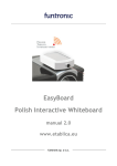
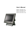
User’s Manual EZPPC-70B-5B-C1G EZPPC-70B-5B-C15G EZPOS-70B-5B-C1G EZPOS-70B-5B-C15G Copyrights ©2009 All rights reserved. The information in this document is subject to change without prior notice in order to improve reliability, design and function and does not represent a commitment on the part of the manufacturer. communications. However, there is no guarantee that interference will not occur in a particular installation. If this equipment does cause harmful interference to radio or television reception, which can be determined by turning the equipment off and on, the user is encouraged to try to correct the interference by one or more of the following This document contains proprietary information measures: protected by copyright. All rights are reserved. No • Increase the separation between the equipment part of this manual may be reproduced by any and the receiver. mechanical, electronic, or other means in any form • Connect the equipment into an outlet on a circuit without prior written permission of the manufacturer. different from that to which the receiver is connected. • Consult the dealer or an experienced radio or All trademarks are property of their respective television technician for help. owners This device complies with Part 15 (B) of the FCC Rules. Operation is subject to the following two Liability Disclaimer In no event will the manufacturer be liable for direct, indirect, special, incidental, or consequential damages arising out of the use or inability to use the product or documentation, even if advised of the possibility of such damages. Regulatory Information FCC Notices conditions: 1) this device may not cause harmful interference and 2) this device must accept any interference received, including interference that may cause undesired operation. NOTE: THE MANUFACTURER IS NOT RESPONSIBLE FOR ANY RADIO OR TV INTERFERENCE CAUSED BY UNAUTHORIZED MODIFICATIONS TO THIS DEVICE. SUCH MODIFICATIONS COULD VOID THE USER'S AUTHORITY TO OPERATE THE DEVICE. This equipment has been tested and found to comply CE Notice with the limits for a Class B digital device, pursuant to Part 15 of the Federal Communications Commission (FCC) Rules. These limits are designed to provide reasonable protection against harmful interference in This device complies with EMC Directive a residential installation. This equipment generates, 2004/108/EC issued by the Commission of the uses, and can radiate radio frequency energy and, if European Community. not installed and used in accordance with the instructions, may cause harmful interference to radio Copyrights i WEEE Notice The WEEE mark applies only to countries within the European Union (EU) and Norway. This appliance is labeled in accordance with European Directive 2002/96/EC concerning waste electrical and electronic equipment (WEEE). The Directive determines the framework for the return and recycling of used appliances as applicable throughout the European Union. This label is applied to various products to indicate that the product is not to be thrown away, but rather reclaimed upon end of life per this Directive. ii Contents Contents Copyrights .................................................................................................i Liability Disclaimer ...................................................................................i Regulatory Information.............................................................................i FCC Notices.......................................................................................................... i CE Notice .............................................................................................................. i WEEE Notice........................................................................................................ ii Contents...................................................................................................iii Introduction ..............................................................................................1 Unpacking the Box...................................................................................3 Hardware Setup........................................................................................4 3.1. Quick Tour............................................................................................... 4 Front View...................................................................................................... 4 Back Panel I/O ............................................................................................... 5 3.2. Connect Battery Pack .................................................................................. 5 3.3. Peripherals Installation................................................................................ 7 Power Adapter ............................................................................................... 7 USB Mouse, USB Keyboard and USB ODD .................................................. 8 LAN Cable...................................................................................................... 8 Cash Drawer .................................................................................................. 8 MSR............................................................................................................... 9 3.4. Adjust View Angle (EZPOS 70 series only) .............................................. 10 3.5. Turn on the Device ..................................................................................... 10 Driver and Utility Installation ................................................................12 4.1. Before the installation................................................................................ 12 4.2. Chipset Software Installation .................................................................... 12 4.3. VGA Driver Installation .............................................................................. 14 4.4. LAN Driver Installation............................................................................... 16 4.5. Audio Driver Installation ............................................................................ 17 4.6. Wireless LAN Driver Installation ............................................................... 19 Power Management ...............................................................................21 5.1. Enter Power Option Properties Sheet ...................................................... 21 5.2. How to Set Power Options ........................................................................ 22 Power Schemes........................................................................................... 22 Alarms.......................................................................................................... 23 Power Meter................................................................................................. 25 Advanced ..................................................................................................... 26 Hibernate ..................................................................................................... 26 TouchKit Utility Quick Guide.................................................................27 Contents iii 6.1. Launch TouchKit Utility ............................................................................. 27 6.2. General........................................................................................................ 28 6.3. Settings ....................................................................................................... 29 6.4. Display ........................................................................................................ 32 6.5. Edge Compensation .................................................................................. 35 I/O Definition...........................................................................................38 7.1. Power Connector ....................................................................................... 38 7.2. Serial Port ................................................................................................... 38 7.3. PS2/COM ..................................................................................................... 39 7.4. Cash Drawer ............................................................................................... 39 Specification...........................................................................................41 iv Contents 1. Introduction Comes with a large 15” TFT 5-Wire Resistive type LCD touchscreen panel, EZPPC 70 (EZPOS 70) features Intel Celeron M 1/1.5 GHZ CPU with 1GB (maximum) SO-DIMM DDR RAM delivering high performance to meet most of requirements from current and future applications. For the thermal issue arising from such hot performance, EZPPC 70 (EZPOS 70) adopts advanced “Fanless” thermal solution which not only keeps the working temperature under the normal value efficiently but also eliminates maintenance cost, voltage consumption and possible failure of CPU cooler. Ultra-slim design combined with maximum strength and durability of ultra slim die-cast aluminum alloy chassis help EZPPC 70 (EZPOS 70) set a new industry PC standard. Thanks to high rigidity die-casting aluminum alloy chassis, EZPPC 70 (EZPOS 70) can defend and resist corrosion and impact damage from any high loaded crucial industry and public service environment. Ultra slim chassis (390mm X 342mm X 58 mm) of EZPPC 70 (EZPOS 70) offers most flexible installation options. With multiple optional installation accessories (for more information, please contact our business representative), EZPPC 70 (EZPOS 70) can be installed in everywhere and meet every installation requirement from every application. Originated and introduced advanced and precision battery technology from notebook, EZPPC 70 (EZPOS 70) is equipped with onboard “smart battery” which is unparalleled in IPC and POS industry. Beyond traditional and dull “battery backup”, EZPPC 70 (EZPOS 70) detects and “communicates” with the onboard smart battery, and allows user to monitor and manage battery allocation depends on variable operation environments as the power management on notebook. The onboard smart battery can supply voltage to EZPPC 70 (EZPOS 70) more than one hour without any external power supply and regulate the power supplied from wall outlet, and to extend the life time of EZPPC 70 (EZPOS 70) to the maximum and reduce electronic failures to the minimum. Combined and equipped with all industry-standard I/O port, EZPPC 70 (EZPOS 70) is an all-in-one touch POS terminal with unlimited flexible compatibility and extensibility to integrate with other accessories and devices. With one cash Chapter 1 1 drawer port, Gigabit Ethernet port, 4 USB 2.0 ports, one RS-232/422/485 port and 3 RS-232 ports equipped, EZPPC 70 (EZPOS 70) can be expanded and connected with all expanded devices required - Wireless LAN, VFD, MSR and iButton…etc, to help user to conquer challenges from variable business markets. For future upgrades and fast assembly/disassembly, EZPPC 70 (EZPOS 70) adopts tool-free and idiot-proof modular design, everyone can assembly/disassembly EZPPC 70 (EZPOS 70) without special tool and install/replace all main modularized components intuitionally. What you benefit from high compatibility and extensibility, easy and fast assembly/disassembly, and modular design of EZPPC 70 (EZPOS 70) are low budget and short maintenance time-cost, which helps enterprise to cut-down cost and make more profit. EZPPC 70 (EZPOS 70) supports most popular Microsoft Windows series operation system (Windows XP Home Edition, Windows XP Professional Edition, WEPOS and Linux, making user spend less effort on technology and softwarerelated issues— so user can devote all energy making your business successful. Features: 2 Intel® low power consumption and high performance technology Durable ultra-slim & robust die-casting aluminum chassis Smart Battery Backup - supply voltage more than one hour without any external power supply Tool-free and modular design - easy upgrade and assembly/disassembly 4x USB 2.0,1 x RS-485/422/232, 3 x RS-232, Gigabit Ethernet port (RJ-11) and cash drawer port (RJ-11) equipped Wireless LAN supported Microsoft Windows series operation system (Windows XP Home Edition, Windows XP Professional Edition and WEPOS) and open-source Linux operation system supported. Chapter 1 2. Unpacking the Box Verify that the box contains the following items. 1 2 3 4 5 6 Chapter 2 Device X 1 Base X 1 (EZPOS 70 series only) Power Adaptor X 1 Power Cord X 1 Driver and utility CD X 1 Wall mount Kit x 1 (EZPPC 70 series only) 3 3. Hardware Setup 3.1. Quick Tour Front View LED Indicator The Power indicator will glow green when power is on. The HDD indicator will blink green when the HDD is accessed. The LAN indicator will blink green when transferring data though the LAN. 4 Chapter 3 Back Panel I/O Note: For details of I/O ports on the back panel, please refer to Chapter 7 – I/O Definition. 3.2. Connect Battery Pack Before power-on the device, please connect the battery to the mainboard: 1. Un-tighten two screws on the back panel anticlockwise. Chapter 3 5 2. Open the back panel. 3. For the location of the battery pack and the 10-1 pin male power connector, please refer the picture shown below. 6 Chapter 3 3. Plug the power cable to the 9-pin power connector in the correct orient. 4. Close the back panel and tighten two screws on the back panel. 3.3. Peripherals Installation Power Adapter Connect the 4-pin output jack of the adapter to the DC 19V jack on the back panel of the device. Chapter 3 7 USB Mouse, USB Keyboard and USB ODD Connect your USB Mouse, USB Keyboard and USB ODD to USB ports on the back panel of the device. LAN Cable Connect one end of RJ-45 LAN cable to the LAN port on the back panel of the device, another end to your internet device. Cash Drawer Connect one end of RJ-11 cable to the Cash Drawer port on the back panel of the device, another end to your cash drawer. 8 Chapter 3 MSR 1. Connect the female connector of the external device to the PS2/COM port on the back panel of the device in the correct orient. 2. Align two screws of the MSR assembly to the holes in blue circles as shown below. 3. Tighten two screws of the MSR assembly as shown below. Chapter 3 9 4. Finished. 3.4. Adjust View Angle (EZPOS 70 series only) Adjust the device to the proper view angle. 3.5. Turn on the Device 1. Make sure all peripherals are connected properly. 2. Press and hold the power switch until the power indicator on the front panel glow green. 10 Chapter 3 Chapter 3 11 4. Driver and Utility Installation 4.1. Before the installation All installation procedures described below are based on Microsoft Windows XP. 1. Connect an external USB CDROM drive to the USB port and insert the driver CD and turn on the device. The program autoruns and displays the DRIVER BANK screen. 2. Click “EZPOS70 /EZPPC70 /EZBOX70 Series”. 4.2. Chipset Software Installation 1. Click INTEL Chipset Driver. 2. Click Next. 12 Chapter 4 3.1. Click Next. 3.2. Read the License Agreement carefully and click Yes. 4. Click Next. Chapter 4 13 5.1. Select restart your computer right now or later. 5.2. Click Finish. 4.3. VGA Driver Installation 1. Click Graphic Driver. 2. Click VGA Driver for WIN2K/XP. 14 Chapter 4 3. Click Next. 3.1. After files extracted, click Next on the welcome screen. 4. Read the License Agreement carefully and click Yes, and then the installation starts. Chapter 4 15 5.1. Select restart your computer right now or later. 5.2. Click Finish. 4.4. LAN Driver Installation 1. Click RTL81x0 LAN Driver. On the welcome screen, click Next. Click Install to begin the installation. 16 Chapter 4 3. Click Finish. 4.5. Audio Driver Installation 1. Click AC’97 Audio Driver. 2. Configures new software installation. Chapter 4 17 3. Click Configure Anyway. 4. AC’97 drivers begins to install. 5.1. Select restart your computer right now or later. 5.2. Click Finish. 18 Chapter 4 4.6. Wireless LAN Driver Installation 1. Click AC’97 Audio Driver. 2. On the welcome screen, click Next, and then the installation begins. Chapter 4 19 3.1. Select restart your computer right now or later. 3.2. Click Finish. 20 Chapter 4 5. Power Management The backup battery equipped on EZPPC 70 (EZPOS 70) series is as “smart” as the battery for Notebook or handheld device; you can adjust any power management option that your unique hardware configuration supports. 5.1. Enter Power Option Properties Sheet There are two alternatives to enter Power Options Properties property sheet. Option 1: 1. Right-click on the Desktop and select Properties. Chapter 5 21 2. Click Screen Saver tab, and then click Power button. Option 2: 1. Click Start, click Settings, click Control Panel, and then double-click Power Options. 5.2. How to Set Power Options Power Schemes 22 Chapter 5 You can configure power settings under Power Schemes tab. Under Power schemes area, click the drop-down list to choose a power scheme to apply settings that fit the way you use EZPPC 70. Under Settings for Home/Office Desk Power scheme area, set all parameters by clicking drop-down lists to put EZPPC 70 (EZPOS 70) on standby mode and turn off your monitor and hard disks automatically to save power upon your actual needs. Alarms You can set two kinds of low battery warning you’ll receive when battery power gets low and what action will be taken for EZPPC 70 (EZPOS 70) under Alarms tab. Low battery alarm and Critical battery alarm Check the box to enable Low battery alarm and Critical battery alarm function. Chapter 5 23 Specify how much power level to activate these two alarms by dragging the green-white slider. Alarm Action Click Alarm Action to enter alarm actions setting sheet. On alarm actions setting sheet, select the type of alarm notification, which action EZPPC 70 (EZPOS 70) will take and which program will launch when the alarm occurs. 24 Chapter 5 Power Meter You can check power status under Power Meter tab. Check or uncheck the box to switch icon view and bar chart view. Under the icon mode, click the battery icon to show the detailed information about the battery. Chapter 5 25 Advanced You can specify power-saving settings by checking boxes in Options area and clicking drop-lists in Power button under Advanced tab. Hibernate Enable the hibernate function by checking Enable hibernation box. 26 Chapter 5 6. TouchKit Utility Quick Guide 6.1. Launch TouchKit Utility There are two alternatives to launch TouchKit. Option 1: Under Microsoft Windows XP, click “start” menu and select “Programs”, under ”TouchKit” menu, click “Configure Utility”. Option 2: Click icon on the task bar to launch TouchKit utility. Chapter 6 27 6.2. General The General tab in Touchkit utility shows all of TouchKit touchscreen controllers installed as below, including RS232, USB and PS2 interfaces. Add The function button is used for serial RS232 controllers only. Press this button to search the TouchKit serial controllers connected with the COM ports of EZPPC 70. Whenever it finds a new TouchKit serial controller, a new serial controller icon object will be shown in the controller list window automatically. USB TouchKit device supports plug and play, the icon object for USB controller will be shown in the controller list window automatically when the USB controller is connected with the USB port of EZPPC 70. And, the icon object for the USB controller will disappear automatically as soon as the device was removed from the USB port of EZPPC 70. TouchKit PS2 driver support PS2 mouse and TouchKit touchscreen controller. It can works with both PS2 mouse and TouchKit touchscreen PS2 controller. After the TouchKit PS2 driver was installed, this utility assumes the PS2 touchscreen controller exists and is always shown in the controller list window. 28 Chapter 6 Remove This function button is used for serial RS232 controllers only. This button will be grayed and disabled automatically when the selected controller in the controller list window is not RS232 type. Press to remove and uninstall the selected serial RS232 controller from EZPPC 70. Then, this serial RS232 icon object in controller list window disappears automatically. USB TouchKit device supports plug and play, the icon object for USB controller will be shown in the controller list window automatically when the USB controller is connected with the USB port of EZPPC 70. And, the icon object for the USB controller will disappear automatically as soon as the device was removed from the system USB port. TouchKit utility does not allow you to remove/uninstall the PS2 device driver dynamically. To uninstall the TouchKit PS2 driver, You needs to go to Windows Device Manager to do un-installation. In addition, after PS2 un-installation, it needs to reboot EZPPC 70 (EZPOS 70) to complete un-installation. 6.3. Settings There are function buttons and check boxes in the Settings tab. Chapter 6 29 Beep Beep On Touch Check this check box to enable driver to generate a beep sound when touch touchscreen state is switched from untouched to touched state. Beep On Release Check this check box to enable driver to generate a beep sound when touchecreen state is switched from touched state to untouched state. Frequency Drag the slider to adjust this frequency to control the beep sound frequency generated by the driver. Duration Drag the slider to adjust this duration to control the beep sound duration. Linearization Style TouchKit utility provides you with both 9 points and 25 points calibration for linearization. You can select the suitable linearization type. Double Click Time Double Click Time is used to set double click time. Change this value will affects the double click behavior for all of the mouse devices connected to EZPPC 70. Two continuous clicks at the same area within this specified time period will be recognized as a double click event. Double Click Area Double click area is used to set the double click area. Change this value will affects the double click behavior for all of the mouse devices 30 Chapter 6 connected to EZPPC 70. Two continuous clicks with this specified area in the specified double click time will be recognized as a double click event. Mouse Emulation Mode Change the emulation mode by pressing on this button. Normal Mode Normal mode behaves mouse button down and mouse move. You can select this mode to select object, and dragging the object. Click On Touch With this Click On Touch mode, the driver emulates a mouse click event when the touchscreen state was switched from un-touched state to touched state. Then, the driver always generate mouse move event and is tracking the touch position until the touchscreen state switched to un-touch state. Click On Release With this Click On Release mode, the driver emulates a mouse click event when the touchscreen state was switched from touched state to un-touched state. Click On Touch without moving cursor With this mode, the driver behaves similar as Click On Touch mode. The cursor does not move to the touch position except the first touch point. Click On Release without moving cursor With this mode, the driver behaves similar as Click On Release mode. The cursor does not move to the touch position except the lift-off point. Chapter 6 31 Option You can set configuration for some advanced functions with this option button. Press this button, a pop up property sheet window will be popped up and shown as below. 6.4. Display TouchKit driver utility supports multiple monitor and display system. To work with multiple monitor system, you need to do proper configuration to map the touchscreen working area to the correct system display area. You can do such configuration with this property page shown as below, 32 Chapter 6 Please follow below instructions to do the configuration: Enable multiple monitor Check this check box to enable multiple monitor support and uncheck it to disable multiple monitor support. When this function is disabled, the touchscreen will be mapped to the primary monitor automatically. When this function is enabled, user can double click on the monitor area in the monitor geometry window to assign the monitor area where the touchscreen will be mapped. In other word, the touchscreen will work with the selected monitor. Then, the selected monitor area rectangle line will be changed to be white and the other monitor rectangles line will be grey. Map to main monitor when the system has only one monitor When the multiple monitor function was enabled, and the system has only one monitor. Driver allows user to generate the mouse event for the primary monitor or not when the touchscreen which were not mapped to primary monitor. Check the check box to enable this function, then, the driver will generate the mouse event for the primary monitor even through the touchscreen was configured as other monitor mapping and multiple monitor function enabled. Operation Mode TouchKit driver support split display mode for those applications which do not map the touchscreen to the full screen of the monitor. Full screen The touchscreen will be mapped to the full screen of the specified monitor. Right screen The touchscreen will be mapped to the right half screen of the specified monitor. Chapter 6 33 Left screen The touchscreen will be mapped to the left half screen of the specified monitor. Upper screen The touchscreen will be mapped to the upper half screen of the specified monitor. Lower screen The touchscreen will be mapped to the lower half screen of the specified monitor. Other operation mode Quarter 1 The touchscreen will be mapped to the first quarter area of the specified monitor display. Quarter 2 The touchscreen will be mapped to the 2nd quarter area of the specified monitor display. Quarter 3 The touchscreen will be mapped to the 3rd quarter area of the specified monitor display. Quarter 4 The touchscreen will be mapped to the 4th quarter area of the specified monitor display. Customized If the touchscreen needs to be mapped the area other than the above area, user can define the mapping area for application. With this mode, the driver does not correct the mapping area when the display resolution changed. It needs to do configuration setting again whenever the display resolution changed. 34 Chapter 6 6.5. Edge Compensation Edge Compensation property page contains functions of Edge Compensation for Top, Bottom, Left, Right, X Axis and Y Axis. In some cases, if it is difficult to touch items at the edges of the touch panel, you can set adjustment to reach the edges of the screen image. Top If you set the Edge to "Smaller", TouchKit will reduce the horizontal position of the top edge. If you set the Edge to "Larger", TouchKit will extend the horizontal position of the top edge. Bottom If you set the Edge to "Smaller", TouchKit will reduce the horizontal position of the bottom edge. If you set the Edge to "Larger", TouchKit will extend the horizontal position of the bottom edge. Left If you set the Edge to "Smaller", TouchKit will reduce the vertical position of the right edge. If you set the Edge to "Larger", TouchKit will extend the vertical position of the left edge. Chapter 6 35 Right If you set the Edge to "Smaller", TouchKit will reduce the vertical position of the right edge. If you set the Edge to "Larger", TouchKit will extend the vertical position of the right edge. In some cases, cursor will be behind the finger when you touch the panel. If you can not see the cursor when you touch down the panel, you can set X Axis or Y Axis to move the cursor. Offset X Axis If you set the Offset X Axis to Smaller, cursor will be moved a pixel of X Axis to left. If you set the Offset X Axis to Larger, cursor will be moved a pixel of X Axis to right. Offset Y Axis If you set the Offset Y Axis to Smaller, cursor will be moved a pixel of Y Axis to top. If you set the Offset Y Axis to Larger, cursor will be moved a pixel of X Axis to bottom. Edge Compensation Switch You can check Support Edge Compensation check box to enable/disable this function from left corner. Edge Compensation Button Click +10% or -10% button to adjust the smaller or larger of edge. If you click +10% button, the top, bottom, left and right edges will extend 10% of orientation to touch screen, and cursor will be moved 10 pixel of X and Y Axis to right and top. If you click -10% button, the top, bottom , left and right edges will contract 10% of orientation to touch screen, and cursor will be 36 Chapter 6 moved 10 pixel of X and Y Axis to left and bottom. Click Default button to resume to the default value. 5.2. How to Use Event Selector 1. On the desktop of Windows, click 2. icon change to icon. . 3. Now the tapping is simulating right mouse button clicking. 4. After one tap on the screen, icon change to . 5. The tapping resumes to left mouse button clicking. Chapter 6 37 7. I/O Definition Please refer the detailed technical information about all I/O ports as followings. 7.1. Power Connector PIN Description PIN Description 1 +19V 3 GROUND 2 +19V 4 GROUND 7.2. Serial Port COM Port 1/2/3/4 38 PIN Description PIN Description 1 DCD 6 DSR 2 RXD 7 RTS 3 TXD 8 CTS 4 DTR 9 RI / 5V /12V 5 GND 10 NC Chapter 7 7.3. PS2/COM PS2/COM PIN Description PIN Description 1 6 PC_CLK )KEYBOARD) 11 CTS 2 GND +5V 7 KB_DAT 12 RTS 3 RXD 8 KB_CLK 13 DSR 4 TXD 9 RI / 5V /12V 14 DCD 5 PC_DAT (KEYBOARD) 10 DTR 15 KB_EN PIN Description 7.4. Cash Drawer Connector Chapter 7 PIN Description PIN Description 1 GND 4 12V -+2 D_OUT 5 NC 3 D_IN 6 GND 39 Cash Drawer Control 40 Status Address Value Open 280H Bit 4 = 0 Close 280H Bit 4 = 1 Read Status 281H Bit 0 = 0/1 Chapter 7 8. Specification Chapter 8 41 Main Board CPU ® Intel Ultra Low Voltage Celeron M 1GHZ w/o L2 cache ® Intel Ultra Low Voltage Celeron M 1.5GHz CPU HZ w/ 1M L2 cache ® Chipset Intel 852GM + ICH4 System Memory SO-DIMM DDR 200/266, 128MB up to 1GB Thermal Solution Fan-less OS Microsoft Windows XP Professional, XPE, WEPOS, Windows CE, Linux Storage Device HDD 1 x 2.5” IDE HDD Compact Flash 1 x Slot, Type II I/O Ports Serial 5x RS-232, 1x RS-232/422/485(COM1), 4 x RS-232 USB 4 x USB 2.0 LAN 1 x RJ45, Gigabit Ethernet PS2/COM 1 x internal for MSR, iButton Cash Drawer 1 x RJ11 (12V) Audio 1 x Audio Out, Integrated with AC 97 CODEC Expansion 1 x Mini PCI Others Power Supply External DC 19V Power Adapter (135W) UPS Power Backup Optional 4P1S battery backup Compliance FCC / CE Weight Approx. 6.5 Kg Dimension 229(W) x 390(D) x 412(H) mm Operation Temperature 5o ~ 35oC, Storage Temperature -20o ~ 60oC, Storage Humidity 20 – 85% RH, non-condensing 42 Chapter 8