1
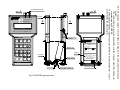
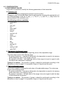
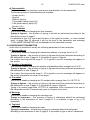
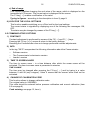
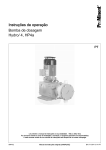
IO.KAP-03.01(ENG)
APLISENS
MANUFACTURE OF PRESSURE TRANSMITTERS
AND CONTROL INSTRUMENTS
USER’S MANUAL
FIELD COMMUNICATOR
KAP-03Ex, KAP-03
WARSAW NOVEMBER 2008
APLISENS JSC. 03-192 Warszawa, ul. Morelowa 7
tel. +48 22 814 07 77; fax +48 22 814 07 78
www.aplisens.pl, e-mail: [email protected]
1
IO.KAP-03.01(ENG)
TABLE OF CONTENTS
1. USE ................................................................................................................................ 3
2. BASIC FEATURES AND TECHNICAL DATA ................................................................ 3
3. LIST OF COMPONENTS ............................................................................................... 4
4. USING KAP-03Ex COMMUNICATOR IN EXPLOSION DANGER ZONES .................... 4
5. CONNECTING AND STARTING THE COMMUNICATOR............................................. 7
6. FINDING THE TRANSMITTER. ..................................................................................... 7
7. UPDATING DATA........................................................................................................... 8
8. MAIN MENU ................................................................................................................... 8
8.1. INFO .......................................................................................................................... 8
8.2. CALIBRATION ........................................................................................................... 9
8.3. CONFIGURATION ................................................................................................... 11
8.4 OPERATING LCD..................................................................................................... 14
8.5 COMMUNICATOR’S OPTIONS................................................................................ 16
9. PROCESS VARIABLES ............................................................................................... 17
10. UPDATING THE COMMUNICATOR’S SOFTWARE BY MEANS OF A PC............. 17
2
IO.KAP-03.01(ENG)
Symbols used
Symbol
i
Description
Warning to proceed strictly in accordance with the information contained in the
documentation in order to ensure the safety and full functionality of the device.
Information particularly useful during installation and operation of the device.
Information particularly useful during installation and operation of Ex device.
Information on disposal of used equipment
BASIC REQUIREMENTS AND SAFE USE
- The manufacturer will not be liable for damage resulting from incorrect
installation, failure to maintain the device in a suitable technical condition, or use
of the device other than for its intended purpose.
- Installation should be carried out by qualified staff having the required authorizations to
install electrical. The installer is responsible for performing the installation in
accordance with these instructions and with the electromagnetic compatibility and
safety regulations and standards applicable to the type of installation.
- The device should be configured appropriately for the purpose for which it is to be used.
Incorrect configuration may cause erroneous functioning, leading to damage to the
device or an accident..
- If a device is not functioning correctly, disconnect it and send it for repair to the
manufacturer or to a firm authorized by the manufacturer.
In order to minimize the risk of malfunction and associated risks to staff, the device is not
to be installed or used in particularly unfavourable conditions, where the following
dangers occur:
- possibility of mechanical impacts, excessive shocks and vibration;
- excessive temperature fluctuation, exposure to direct sunlight;.
Installation of intrinsic safety versions should be performed with particular care, in
accordance with the regulations and standards applicable to that type of installation.
The technical manual contains parameters for the transmitters which were correct at the time
of going to press. These parameters may be changed.
The manufacturer reserves the right to make changes (not having a negative impact on the
operational and metrological parameters of the products) without updating the contents of the
technical manual..
A current version of the technical manual, as well as declarations of conformity, can be found
at www.aplisens.pl.
3
1.
IO.KAP-03.01(ENG)
USE
The KAP-03 and KAP-03Ex field communicator is a portable device with its own battery
power supply, used for communication and exchange of data with intelligent transmitters
e. g. pressure, differential pressure, temperature transmitters. It features an output built as
a standard current loop 4-20 mA, using FSK modulation type BEL202 with an implemented
HART communication protocol revision 5 and revision 6.
The communicator is specially designed to configure intelligent transmitters manufactured
by APLISENS.
Depending on the software implemented in the controller, it can be used to configure
pressure transmitters (APC-2000PD, APC-2000PZ, APC-2000AL, APC-2000ALW,
APC-2000ALE), pressure difference transmitters (APR-2000PD, APR-2000PZ,
APR-2000AL, APR-2000ALW, APR-2000ALE, APR-2200PD, APR-2200PZ, APR-2200AL,
APR-2200ALW, APR-2200ALE) and hydrostatic depth probes (SG-25.Smart,
SG-25S.Smart, APR-2000Y) or transmitters of other physical quantities, e.g. temperature
transmitters.
The communication with the transmitters enables:
− Identification of a transmitter,
− Configuration of its output parameters:
Units and values of the beginning and the end of its measurement range,
Ballistic factor,
Conversion characteristics (linear, radical, special, quadratic),
− Reading of a currently measured value (e.g. pressure, output current, degree of output
setting in %),
− Enforcement of output current with a given value,
− Transmitter calibration as regards master pressure,.
− Zeroing
The link to a detailed description of the functional software of the profile for pressure,
temperature, etc. is located on this site http://www.aplisens.pl/produkty/kap.html or can be
found in the “KAP Loader 1” software in the box “Server viewer”.
2.
BASIC FEATURES AND TECHNICAL DATA
•
•
•
•
•
•
•
•
•
•
Autonomous power supply from a lithium battery (3.6V / 1.5 Ah).
Power consumption when active app. 8.5 mA.
Power consumption when off app. 40 µA.
Estimated time of constant operation with fully charged battery – app. 7 days.
Automatic switch off after preprogrammed period of inactivity.
Communicates displayed on an alphanumerical display 2x20 characters.
Adjustment of contrast of the displayed characters.
Plastic film keyboard to input data.
Acoustic signaling of event (e.g. pressed key).
Communication in BELL202 standard, protocol HART rev5 and rev6 with adaptive
adjustment of carrier amplitude.
Operation with a resistor placed in the transmitter’s current loop, with a resistance from
220 to 1100 Ohm.
Possibility to connect an external power supply (9V stable /200mA) through the charging
connector, in order to charge the communicator’s battery.
Battery charge time up to app. 8h for KAP-03 and up to app. 16h for KAP-03Ex
•
•
•
4
•
IO.KAP-03.01(ENG)
Possibility to change the communicator’s software by means of a KAP Loader program
using a mini USB connector (USB 1.1 or USB 2.0).
EMC requirements fulfilled.
Operating temperature range -10ºC ≤ Ta ≤ 50ºC
•
•
If the KAP-03Ex device was stored in a low temperature, it should be warmed up to the
room temperature before switching on.
Available in intrinsic safety version: Communicator designated as KAP-03Ex is designed to
be used in explosion danger zones (see point 4).
3. LIST OF COMPONENTS
The item consists of the following:
- communicator KAP-03Ex or KAP-03
- cover (for version KAP-03Ex the cover is marked as KAP03AE)
- connection wires with gripping devices
- connection cable USB
- ”Operation manual”
- Certificate of conformity for KAP-03Ex (certificate for KAP03 at request)
Declaration and ATEX certificates are available at www.aplisens.pl
4.
USING KAP-03Ex COMMUNICATOR IN EXPLOSION DANGER ZONES
4.1. Introduction
Communicator in intrinsic safety version is designated as KAP-03Ex.
Communicator in normal version is designated as KAP-03.
Point 4 apply to KAP-03Ex. Other points apply to KAP-03Ex and KAP-03
4.2. Use of KAP-03Ex communicator in explosion danger zones
4.2.1. KAP-03Ex communicator is produced according to standards:
PN-EN60079-0:2006, PN-EN60079-11:2007
4.2.2. KAP-03 Ex communicators may be used in explosion danger zones marked with an
anti-explosion structure marking.
II2GEEx ia IICT4
KDB 07 ATEX 122X
It can also be used under conditions taking into account the following input/output
parameters:
Uo / Ui = 3,9V / 28VDC
Io / Ii = 17mA / 93mA (linear)
Po / Pi = 11mW / 1W
Ci = 26nF (2,2µF + 10% / 220Ω),
Li = 0
4.3. Identification and warning signs
4.3.1. Communicators in Ex version must feature permanent signs located on their body and
cover:
- company logo and device type designation
- CE marking and notified unit number
- antiexplosion structure designation according to point 4.2.2
- Use in the cover KAP03AE only
i
5
IO.KAP-03.01(ENG)
4.3.2. Additionally, the communicator's body should feature the following:
- serial number and year of production
- output/input parameters
- the following inscription must be located near the power socket
„Charge with 9V ±2% only in explosion safe zone”.
4.4. Power
The communicator is powered by a lithium-ionic battery with nominal capacity of
1.55Ah and voltage 3.6V.
The battery and its protective elements form a unit covered in polyurethane resin and
has the shape of a rectangular cube.
The charging socket is designed to match a concentric plug with an orifice, with its
outside diameter of 5.5m and a bolt Ø2,5mm.
The charging circuit is protected at its beginning with a tube fuse In=160mA Un=250V
The fuse with a frame is placed on the side of the battery and forms its part.
The fuse can be accessed by unscrewing the housing of the communicator, slightly
lifting the battery and removing the cover of the fuse socket (Fig.1).
The communicator may be powered only by means of the above described battery set
manufactured by APLISENS.
The set is replaced in a safe zone by detaching the set from the PCB and unsoldering
input wires from the terminals of the charging socket.
The set may only be performed by the manufacturer or a unit authorized by the
manufacturer.
i
4.5. Use
4.5.1. KAP-03Ex communicator in Ex version may be used only in the cover supplied
together with the communicator with permanently applied designations as per point
4.3.1.
Information on the method of connecting to the charging and measurement line as well
as features and functionalities, the method of setting the unit, taking readouts when the
communicator is working together with a converter are specified in the latter part of the
User's Manual.
4.5.2. Charging
The discharged battery is indicated by a blinking battery light on the display.
The battery of KAP-03Ex communicator is charged by connecting a mains charger plug
with a coaxial plug with internal connection diameter of 5,5mm and plug orifice Ø2.1mm to
the charging socket.
Output voltage of the charger is stabilized and has a nominal value of 9VDC±2%,
output current app. 200mA.
Charger output voltage is insulated from the mains with a transformer with reinforced
insulation (designation
).
The communicator should be charged only in a safe zone. While charging, it is not
allowed to connect the communicator's measurement clamps to the signal line leading
to the danger zone.
If the battery is fully charged, the communicator may operate for app. 170 hours non stop
(7 days).
Charging from the moment the battery is fully discharged until fully charged is app. 16 hours.
Connecting terminals
A
B
view
KAP-03 Ex
II 2G Ex ia IIC T4
KDB 07ATEX...
Screw
B
A
UŜywać tylko w pokrowcu KAP03AE
Use in the cover KAP03AE only
F1
F2
F3
F4
03-192 WARSZAWA
ul. Morelowa 7
tel. (022) 814 07 77
www.aplisens.pl
PRODUKCJA PRZETWORNIKÓW CIŚNIENIA
I APARATURY POMIAROWEJ Sp.z o.o.
PF RE PV
FIELD COMMUNICATOR
KAP-03Ex
ON
OFF
Numer fabryczny:
Rok produkcji:
Battery set
1453
II 2G Ex ia IIC T4
KDB 07ATEX. . .
DEF
GHI
@%&
0
7
8
9
JKL
MNO
PQR
4
5
6
STU
VWX
YZ#
1
2
3
+/*
-
Uo/Ui = ...
Po/Pi = ...
Rating
plate
Charging
socket
Fuse socket
[
ABC
.
Fig.1 KAP-03Ex general view
Fuse O5x20 EN60127
In=0,16A, U=250V F
Li = ...
-10oC ≤ Ta ≤ 50oC
Zasilanie : własne, iskrobezpieczny
zespół baterii 3,6 VDC
Charge with supply 9 VDC±2%
outside danger zone
Ładować napięciem 9VDC±2%
tylko poza strefą
zagroŜenia wybuchem
Charging socket
IO.KAP-03.01(ENG)
Fuse cover
Io/Ii = ...
Ci = ...
6
Programming
socket
4.5.3. No changes, repairs or interventions are allowed in the communicator's electronic
system.
The communicator may not be powered by sources of power other than battery set
manufactured by APLISENS.
The damage analysis and repair may only be performed by the manufacturer or a unit
authorized by the manufacturer.
view
7
5.
IO.KAP-03.01(ENG)
CONNECTING AND STARTING THE COMMUNICATOR
min 250 Ω
4...20mA
Transmitter
or probe
+
Power
supply
Communicator
_
Fig.2. Schematics of connecting KAP-03 communicator to the power and measurement line
of the transmitter or probe
Communicator KAP-03 is started by pushing the ON/OFF key.
After switching it on a welcome picture is displayed on the Communicator’s screen, showing
the producer’s name and the Communicator’s type.
The line’s amplitude is automatically adjusted depending on the line loading that ranges
between 250Ω and 1100Ω
6.
FINDING THE TRANSMITTER.
During searching for the transmitter the progress bar shows on the Communicator’s screen.
In the searching time addresses from 0 to 15 are inspected. The procedure is repeated at
maximum three times.
If the transmitter possesses address 0 the Communicator will find it, and stop searching.
After the search has been finished the address of the found transmitter and its serial number
are displayed. Then pushing any key causes change to the mode of updating.
FOUND DEVICE
ADDRESS:
ID NR:
> ANY KEY<
If the transmitter possesses any other address than 0 it is possible to search for other
devices after having pushed key F4 [>>>].
FOUND DEVICE
ADDRESS:
ID NR:
[
][
] [ ENTER] [ >>> ]
If the Communicator does not find the transmitter a message appears on the display
informing that it is possible to restart it by pushing key F1 [RESTART].
--- NO DEVICE--CHECK CONNECTION
[RESTART ] [
][
][
]
8
IO.KAP-03.01(ENG)
7. UPDATING DATA
After the transmitter has been found its data become updated. The progress bar is
displayed on the Communicator’s screen. After data update the main MENU appears on
the screen. The transmission between the Communicator and the transmitter is signalled
by the pulsing cursor in the upper left corner of the screen.
8. MAIN MENU
The way of moving over the main menu is described by means of the following signs:
− sign [ < ] - means moving to the left along the same MENU level
− sign [ > ] - means moving to the right along the same
− sign [↵ ] - means moving to the MENU level below or command confirmation
− sign [ ↑ ] – means moving to the MENU level above.
The Communicator’s keys:
− RE – collecting data from the transmitter
− PF – key unavailable
− PV – process variables
− F1, F2, F3,F4 – function keys
8.1. INFO
This tab enables viewing the transmitter’s parameters and data.
Pressing key F4 [REFRESH] causes renewed taking data from the transmitter.
The [REFRESH] function may also be activated by pressing key RE at any time.
The following parameters are available:
1)
2)
3)
4)
5)
6)
7)
8)
9)
10)
11)
12)
13)
14)
15)
16)
17)
18)
19)
20)
21)
22)
23)
24)
25)
26)
27)
IDENTIFICATION NUMBER
MESSAGE Key F3 [>>>] enables scrolling through the whole message.
DATUM
TAB LABEL
TAB DESCRIPTION
SERIAL NUMBER
CHARACTERISTIC
UNITS
UPPER LIMIT OF RANGE
LOWER LIMIT OF RANGE
BEGINNING OF ADJUSTABLE RANGE
END OF ADJUSTABLE RANGE
MINIMUM BREADTH OF RANGE
TIME CONSTANT
SAVING LOCK
DEVICE ADDRESS
NUMBER OF PREAMBLES
HEAD NUMBER
ELECTRONICS VERSIONS
PROGRAMME VERSION
TSD
UCS
MANUFACTURER’S CODE OF DEVICE
MANUFACTURER’S CODE OF IDENTIFICATION
DISTRIBUTOR CODE
FLAGS
Error flags
9
IO.KAP-03.01(ENG)
If the value of errors amounts to 0 it means that there were no errors notified during the
transmission, and no configuration change took place.
If the value of an error flag is different from 0 then in the upper left corner of the screen an
exclamation sign appears.
The errors may be removed by running the "RESET CONFIGURATION FLAG" function
which is available at the „CONFIGURATION – transmitter configuration” tab. After this
action the exclamation sign displayed in the upper left corner of the screen vanishes.
8.2. CALIBRATION
1) ZEROING
The function for zeroing the transmitter is performed in order to eliminate the shift in its
characteristic after installing it on a new object. After the ZEROING function has been
executed the pressure becomes stabilised and the current pressure is displayed on the
Communicator’s screen in the form of a number and unit. If the displayed value is
appropriate the zeroing operation should be acknowledged by pressing the F3 key [ ↵ ].
The Communicator confirms performance of the zeroing by displaying the following
message: „FIRST PROCESS VARIABLE ZEROED”.
2) PRESSURE CALIBRATION
Before calibration ought to be enter calibration code: 00000000.
Change of calibration code: see item 8.5. options of communicator page no. 16.
This function enables calibrating the upper and the lower value of pressure.
The to be calibrated is chosen by pressing the key F1 [ < ] or the F2 key [ > ] and
acknowledged by pressing the F3 key [ ↵ ].
-PRESSURE CALIBRATION.
PRESSURE CALIBRATION
SET LOWER PRESSURE
SET UPPER PRESSURE.
[ < ][ > ][ ↵ ][ ↑ ]
[ < ][ > ][ ↵ ][ ↑ ]
After choosing the pressure to be calibrated (the upper or the lower one) the pressure
becomes stabilised and the current pressure is displayed on the Communicator’s screen
in the form of number and unit. When the chosen pressure is displayed it should be
acknowledged by pressing the F3 key [ ↵ ] and the master pressure value should be
typed in.
Typing in figures
Moving on the screen is possible with the use of the F1 key [ < ] and F2 key [ > ].
A single short pressing the F1 key [ < ] causes removing one character before the
cursor whereas a longer pressing it results in removing the whole line.
A text box may be modified when the pulsing cursor is present in it. Figures may be
typed in by pressing appropriate keys of the keyboard. Pressing the F3 key [ ↵ ] causes
input of the typed in value, then the cursor vanishes. It is possible to type in up to 5
figures and the point. After typing in each character the cursor automatically moves to
the next position right after the newly typed in character.
It is possible to type in for example figure 2 instead of 02 without fear – both forms are
accepted by the device.
It is possible to type in up to 5 figures and the point.
10
IO.KAP-03.01(ENG)
After carrying out calibration operation the Communicator displays message
„CALIBRATION SUCCESSFULLY EXECUTED”.
MASTER PRESSURE
PRESS. STABILISATION.
XXXXXX
[
][
PRESSURE CALIBRATION
TYPE IN
- WAIT!-
XXXXX❚
XXX
XXX
[ < ][ > ][ ↵ ][ ↑ ]
][ ↵ ][ ↑ ]
SUCCESSFULLY
EXECUTED
[
][
][
] [ OK ]
The values of assumed calibration points do not have to be equal to the upper and
bottom limits of the basic range but these may not go beyond them, i.e. be higher and
lower respectively. The breadth of the calibration range may not be smaller than the
minimum breadth of set range. In order to reach the best possible accuracy it is
recommended that the calibration points and the beginning and end points of the set
range have the same or near values.
3) CURRENT CALIBRATION
Before calibration ought to be enter calibration code: 00000000.
Change of calibration code: see item 8.5. options of communicator page no. 16.
a) The upper or bottom limit of range
- CURRENT CALIBRATION
SET I (0 - 22mA)
X.XXXX❚
mA
[ < ][ > ][ ↵ ][ ↑ ]
READ CURRENT VALUE
CURRENT CALIBRATION
VALUE AT AMMETER
CALIBRATE I (0 - 22mA)
X.XXXX❚
AND TYPE IT IN
[
][
][
] [ OK ]
mA
[ < ][ > ][ ↵ ][ ↑ ]
The Communicator confirms performance of the calibration by displaying massage:
„CURRENT CALIBRATION SUCCESSFULLY EXECUTED”
b) Setting a current of 4 mA or 20 mA
CURRENT ON-LINE
SET:
4mA
[
][
][
READ CURRENT VALUE
CURRENT CALIBRATION
VALUE AT AMMETER
CALIBRATE I (0 - 22mA)
X.XXXX❚
AND TYPE IT IN
] [ OK ]
[
][
][
] [ OK ]
mA
[ < ][ > ][ ↵ ][ ↑ ]
The Communicator confirms performance of the calibration by displaying massage
„CURRENT CALIBRATION SUCCESSFULLY EXECUTED”
4) RESETTING THE ORIGINAL VALUES
This function enables return to the settings that have been done at the production stage
of the transmitter:
a) Zeroing
b) Pressure calibration
c) Current calibration
11
IO.KAP-03.01(ENG)
8.3. CONFIGURATION
1) CONFIGURING VALUES
In this tab it is possible to modify the following parameters of the transmitter:
a) Pressure unit
This function enables changing the pressure unit to be used.
Changing to the unit that should be used is performed by choosing the appropriate unit
and acknowledging it with the F3 key [ ↵ ]. The F1 [ < ] and F2 [ > ] keys serve for
moving between the available units.
The following units are available:
− FtH2O 68°F
− kPa
− InHg 0°C
− Pa
− InH2O 68°F
− kG/cm²
− G/cm²
− mmH2O 4°C
− mbar
− InH2O 4°C
− bar
− MPa
− psi
− ATM
− mmHg 0°C
− Torr
− mmH2O 68°F
− mH2O 4°C
b) Beginning of adjustable range
This function enables changing the beginning value of the adjustable range.
The value may be set in the following ways:
− By giving a pressure – a pressure delivered to the transmitter is saved in its memory
as the beginning value of the range to be set.
− By typing in a number – the beginning value of the range to be set is typed in with
the help of the transmitter’s keyboard.
Typing in a number – the process of typing in should be performed according to the
description in item 2) page 9. It is possible to type in 5 figures and the point.
c) End of adjustable range
This function enables changing the end value of the adjustable range. The value may
be set in the following ways:
− By giving a pressure – a pressure delivered to the transmitter is saved in its memory
as the end value of the range to be set.
− By typing in a number – the end value of the range to be set is typed in with the help
of the transmitter’s keyboard.
Typing in a number – the process of typing in should be performed according to the
description in item 2) page 9. It is possible to type in 5 figures and the point.
12
IO.KAP-03.01(ENG)
d) Characteristic
This function enables choosing a conversion characteristic for the transmitter.
The following kinds of characteristics are available:
− Linear (mx+b)
− Special
− Radical (sqrt(x))
− Third grade radical (sqrt(x^3))
− Fifth grade radical (sqrt(x^5))
− Square (x^2)
e) Time constant
This function enables changing the time constant.
Typing in figures – the process of typing in should be performed according to the
description in item 2) page 9.
It is possible to type in 5 figures and the point. If the typed in number, i.e. time constant
value, is larger than 30 seconds it will not be sent to the transmitter and message
“TOO LARGE PARAMETER” will be displayed on the transmitter’s screen.
2) CONFIGURING TRANSMITTER
In this tab it is possible to modify the following parameters of the transmitter:
a) Device address
This function enables changing the transmitter address in a range from 0 to 15
Typing in figures – the process of typing in figures should be performed according to
the description in item 2) page 9. It is possible to type in 2 figures.
If a number from beyond the range 0 - 15 is typed in an error message will appear on
the screen.
b) Number of preambles
This function enables changing the number of preambles within a range from 3 to 20
Typing in figures – the process of typing in figures should be performed according to
the description in item 2) page 9.
If a number from beyond the range 3 - 20 is typed in an error message will appear on
the screen (parameter too small or too large).
c) ID number
This function enables changing the ID number within a range from 0 to 16777215.
Typing in figures – the process of typing in figures should be performed according to
the description in item 2) page 9. It is possible to type in 8 figures.
Typing in a number larger than 16777215 is impossible. Such command is not sent to
the transmitter and the Communicator goes to a higher menu level.
d) Message
This function enables changing the message text.
Typing in characters – the process of typing in characters should be performed
according to the description in item 2) page 9. It is possible to type in up to 32
characters.
e) Tag label
This function enables changing the label.
Typing in characters – the process of typing in characters should be performed
according to the description in item 2) page 9. It is possible to type in up to 8 characters.
13
IO.KAP-03.01(ENG)
f) Tag description
This function enables changing the description.
Typing in characters – the process of typing in characters should be performed
according to the description in item 2) page 9. It is possible to type in up to 16
characters.
g) Tag date
This function enables changing the date in the following format: XX.XX.XXXX (day,
month, year)
Typing in characters – the process of typing in characters should be performed
according to the description in item 2) page 9 in accordance with the above-presented
format.
h) Head number
This function enables changing the head number within a range from 0 to 16777215.
Typing in characters – the process of typing in characters should be performed
according to the description in item 2) page 9. It is possible to type in up to 8
characters.
Typing in a number larger than 16777215 is impossible. Such command is not sent to
the transmitter and the Communicator goes to a higher menu level.
i) Changing the lock code
This function enables changing the lock code.
The lock code consists of 8 characters.
Typing in the code
All the characters must be typed in otherwise the Communicator does not accept it and
goes to a higher menu level. The following characters may be typed in: 0, 1, 2, 3, 4, 5,
6, 7, 8, 9, A, B, C, D, E, F. Other characters are locked. Each character is typed in by
one short pressing an appropriate key. The typed in characters may not be removed,
these may only be overwritten. In order to change the code one must fill out the line
OLD and the line NEW with eight characters and then acknowledge it by pressing the
F3 key [ ↵ ].
--- LOCK CODE CHANGE OLD: 1234567❚
NEW: 1234567❚
[ < ][ > ][ ↵ ][ ↑ ]
The Communicator confirms each correctly performed operation by displaying
message „CODE CHANGED”, and pressing the F3 key [ ↵ ] enables its saving. If the
lock code is typed in incorrectly the Communicator signals that situation by displaying
message „INCORRECT CODE” - then press the F3 key [ ↵ ] to be given a repeated
chance of typing in the code.
j) Saving lock
This function enables switching on and switching off the saving lock by providing an
appropriate code.
Typing in the code – according to the description in item i) page 13.
14
IO.KAP-03.01(ENG)
k) Alarm mode
This function enables switching on and off the alarm mode.
The alarm mode is switched on by pressing the F3 key [ ↵ ] and typing in the code of
that alarm, which should be activated – in accordance with the description in the
following table
A full code is a sum of component codes described in the following table.
CODE
1
2
4
8
64
128
DESCRIPTION
Error of a measuring circle break – dynamic signalling
0 – no error, 1- error
Errors in the ADC transmitter – static signalling,
0 – no error, 1- error
Errors of RAM, EEPROM, PROGRAM - static signalling
0 – no error, 1- error
Errors in the local quartz oscillator, processor or transmitter oscillator static signalling 0 – no error, 1- error
Alarm current
0 – high (22 mA), 1 – low (3.6 mA)
Current range Mod
0-normal (range 3.9-20.5mA, 1 – NAMUR-Compilant (range 3.8-20.5mA)
Typing in the alarm code – the process of typing in characters should be performed
according to the description in item 2) page 9. It is possible to type in 3 characters.
l) External push-button
This function enables switching on and off the possibility of zeroing and setting the
beginning and end of range by delivery of a pressure, by means of magnetised
elements (casing AL and ALW) or external push-buttons (casing ALE).
m) Resetting configuration flags
This function enables removal of transmission errors.
8.4 OPERATING LCD
This function is available only for the transmitters equipped with an LCD display.
1) SWITCHING ON / OFF LCD.
This function enables switching on and off the LCD display.
2) REVERSE
This function enables displaying values on the transmitter’s LCD display in the reverse
form.
3) TURN
This function enables turning the values displayed on the LCD display by 180º.
After executing this function the message about restarting is displayed. The effect of the
turning of the displaying is visible after the restarting.
15
IO.KAP-03.01(ENG)
4) PROCESS VARIABLES
This function enables displaying an appropriate process variable on the LCD screen of
the transmitter.
It is possible to display values of current, pressure, range percentage or user’s range.
5) COMMA
This function enables setting a comma in any position of the number displayed on the
transmitter’s LCD screen.
6) CONTRAST
Contrast adjustment is performed by means of the F2 [ + ] and F1 [ - ] keys. Pressing
the F3 key [ >|< ] causes a return to the in-factory pre-set settings. Resetting the
Communicator does not change performed contrast adjustments.
7) USER’S RANGE
a) User’s units
This function enables changing units in which the values are displayed on the
transmitter’s LCD screen. After displaying the current user unit and pressing the F3
key [ ↵ ] units may be changed.
Typing in characters and figures
Moving among the units is performed by means of the F1 [ < ] and F2 [ > ] keys.
The pulsing cursor indicates the current cell of the display where changes may be
performed. By pressing an appropriate key of the keyboard we can type in figures and
letters (only block letters). Changing letters and figures is performed by one pressing a
key or by pressing a key for a longer time, in the latter situation figures and letters
change in a continuous way. Pressing the F3 key [ ↵ ] acknowledges the typed in
value (cursor vanishes). It is possible to type in 15 characters.
After typing in a character the cursor does not automatically move to the next position
therefore it must be shifted by means of the F2 key [ > ].
--------USER RANGE.--------USER UNIT.
ABCDEFGHIJKL❚NO
[ < ][ > ][ ↵ ][ ↑ ]
b) Beginning of range
This function enables changing the beginning value of the range, which is displayed on
the transmitter’s LCD screen. The current value is displayed on the screen. The F3 key
[ ↵ ] enables modification of the value.
Typing in figures
Moving on the screen is possible by means of the F1 [ < ] and F2 [ > ] keys.
A single pressing the F1 [ < ] key enables removing the character situated on the left of
the cursor whereas holding it pressed causes removal of the whole line.
A given cell may be modified when the pulsing cursor is situated in it. By pressing an
appropriate key of the keyboard we may type in figures. Figures are changed by single
key pressing. Pressing the F3 key [ ↵ ] acknowledges the typed in value (the cursor
vanishes). It is possible to type in 5 figures and the point. After typing in each character
the cursor automatically changes its position for the next one.
A comma (point) may be typed in at a arbitrary chosen place except for the first
position.
16
IO.KAP-03.01(ENG)
c) End of range
This function enables changing the end value of the range, which is displayed on the
transmitter’s LCD screen. The current value is displayed on the screen.
The F3 key [ ↵ ] enables modification of the value
Typing in figures – according to the description in item 2) page 9.
8) LOCK FOR THE LOCAL SETTINGS
This function enables switching on or off the lock for the local settings.
The current status is signalled by displaying one of the following two messages: ON,
OFF.
The status may be changed by means of the F3 key [ ↵ ].
8.5 COMMUNICATOR’S OPTIONS
1) CONTRAST
Contrast adjustment is performed by means of the F2 [ + ] and F1 [ - ] keys.
Pressing the F3 key [ >|< ] causes a return to the factory settings.
Resetting the Communicator does not change performed contrast adjustments.
2) INFO
In the tag "INFO" incorporates the following information about the Communicator:
−
−
−
Software version
The Communicator’s electronics version
Loader’s version
3) TIME TO SCREEN SAVER
The time to screen saver – is a time distance after which the screen saver will be
activated. The time to screen saver is presented in minutes
TIME CHANGE
The time may be changed after pressing the F3 key [ ↵ ] and by typing in a value
between 0 and 99 (only integers). Value 0 means that the screen saver shall not be
activated.
4) CHANGE OF CALIBRATION CODE
This function allows to change calibration code.
The original value is: 00000000.
This code should be entered before pressure calibration and current calibration (item
8.2 see page 9)
Code entering: see page 13, item i).
17
9.
IO.KAP-03.01(ENG)
PROCESS VARIABLES
This function is available after pressing the PV key on the Communicator. It enables current
viewing the following process variables:
− FIRST PROCESS VARIABLE PV
− SECOND PROCESS VARIABLE SV
− THIRD PROCESS VARIABLE TV
− FOURTH PROCESS VARIABLE FV
− RANGE PERCENTAGE
− CURRENT (MA)
The information is refreshed every 0.9 seconds. Moving between the available variables is
possible by means of the F1 [ < ] and F2 [ > ] keys.
10. UPDATING THE COMMUNICATOR’S SOFTWARE BY MEANS OF A PC
In order to update the software one must:
a) Start the "KAP Loader" programme on the PC
b) Connect the Communicator to the PC using USB
c) Switch on the Communicator (if the Communicator was on during connecting it to the PC
it should be switched off and again switch on)
d) Follow the operating instructions set out in the documentation of “KAP Loader”
The Communicator confirms each successful connection to the PC by a single beep (while
the LCD screen is blank). The KAP Loader programme signals successful connection by
showing a moving stripe in the lower right corner of the PC display screen (this stripe is not
presented in case of the operating system Windows 98). Breaking the communication with
the PC (before completing the transmission between KAP Loader and the Communicator,
e.g. by disconnecting the USB cable) causes that the Communicator leaves the mode of
software replacement. Then the procedure should be repeated beginning with the step /
item b).


![[17] User`s Manual ver. 2.0.2](http://vs1.manualzilla.com/store/data/005765389_1-e376d351ef2708f30fcfdc5f98b9ba18-150x150.png)