
1
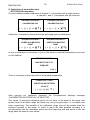
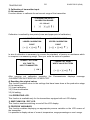
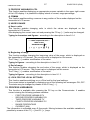
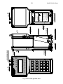
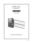
IO.KAP-03.02(ENG)
APLISENS
MANUFACTURE OF PRESSURE TRANSMITTERS
AND CONTROL INSTRUMENTS
USER’S MANUAL
FIELD COMMUNICATOR
KAP-03Ex, KAP-03
Edition A
WARSAW JANUARY 2013
APLISENS. S.A., 03-192 Warszawa, ul. Morelowa 7
tel. +48 22 814 07 77; fax +48 22 814 07 78
www.aplisens.pl, e-mail: [email protected]
Symbols used
Symbol
i
Description
Warning to proceed strictly in accordance with the information contained in the
documentation in order to ensure the safety and full functionality of the device.
Information particularly useful during installation and operation of the device.
Information particularly useful during installation and operation of Ex device.
Information on disposal of used equipment
BASIC REQUIREMENTS AND SAFE USE
- The manufacturer will not be liable for damage resulting from incorrect
installation, failure to maintain the device in a suitable technical condition, or
use of the device other than for its intended purpose.
- Installation should be carried out by qualified staff having the required authorizations to
install electrical. The installer is responsible for performing the installation in
accordance with these instructions and with the electromagnetic compatibility and
safety regulations and standards applicable to the type of installation.
- The device should be configured appropriately for the purpose for which it is to be used.
Incorrect configuration may cause erroneous functioning, leading to damage to the
device or an accident.
- If a device is not functioning correctly, disconnect it and send it for repair to the
manufacturer or to a firm authorized by the manufacturer.
In order to minimize the risk of malfunction and associated risks to staff, the device is not
to be installed or used in particularly unfavourable conditions, where the following
dangers occur:
- possibility of mechanical impacts, excessive shocks and vibration;
- excessive temperature fluctuation, exposure to direct sunlight;.
Installation of intrinsic safety versions should be performed with particular care, in
accordance with the regulations and standards applicable to that type of installation.
Changes in the production of transmitters may precede a paper updating for the user - the
current user manuals are available at http. www.aplisens.pl.
A current version of the technical manual, as well as declarations of conformity, can be found
at www.aplisens.pl.
1
IO.KAP-03.02 (ENG)
TABLE OF CONTENTS
1.
2.
3.
4.
5.
6.
7.
8.
9.
USE APLICATION ......................................................................................................... 2
BASIC FEATURES AND TECHNICAL DATA ................................................................ 2
LIST OF COMPONENTS ............................................................................................... 3
USING KAP-03Ex COMMUNICATOR IN EXPLOSION DANGER ZONES .................... 3
EXCHANGE OR UPDATING THE COMMUNICATOR’S SOFTWARE BY MEANS OF A
PC .................................................................................................................................. 5
CONNECTING AND STARTING THE COMMUNICATOR ............................................. 6
FINDING THE TRANSMITTER. ..................................................................................... 6
UPDATING DATA. ......................................................................................................... 7
MAIN MENU ................................................................................................................... 7
9.1. INTRODUCTION........................................................................................................................ 7
9.2 COMMUNICATOR’S OPTIONS. ................................................................................................. 8
I PRESSURE TRANSMITTERS ......................................................................................... 8
9.3. INFO .......................................................................................................................................... 8
9.4 CONFIGURATION ...................................................................................................................... 9
9.5 CALIBRATION .......................................................................................................................... 13
9.6 OPERATING LCD. .................................................................................................................... 15
10. PROCESS VARIABLES ............................................................................................... 16
II TEMPERATURE TRANSMITTERS ............................................................................... 17
11.1 INFO ....................................................................................................................................... 17
11.2 CONFIGURATION .................................................................................................................. 19
11.3 CALIBRATION ........................................................................................................................ 24
11.4 OPERATING LCD. .................................................................................................................. 26
12. PROCESS VARIABLES .............................................................................................. 27
FIG.1 KAP-03EX GENERAL VIEW ....................................................................................................... 28
FIG.2 COVER OF KAP-03EX COMMUNICATOR ..................................................................................... 29
2
1.
IO.KAP-03.02 (ENG)
USE APLICATION
The KAP-03 and KAP-03Ex field communicator is a portable device with its own battery
power supply, used for communication and exchange of data with intelligent transmitters
e. g. pressure, differential pressure, temperature transmitters. It features an output built as
a standard current loop 4-20 mA, using FSK modulation type BEL202 with an implemented
HART communication protocol revision 5 and revision 6.
The communicator is specially designed to configure intelligent transmitters manufactured
by APLISENS.
The KAP-03 and KAP-03Ex depending on the loaded software can handle one of two
groups of Aplisens transmitters:
1)
The pressure transmitters, differential pressure transmitters and hydrostatic level
probes:
APC-2000PD, APC-2000PZ, APC-2000AL, APC-2000ALW, APC-2000ALE,
APR-2000PD, APR-2000PZ, APR-2000AL, APR-2000ALW, APR-2000ALE,
APR-2200PD, APR-2200PZ, APR-2200AL, APR-2200ALW, APR-2200ALE,
SG-25.Smart, SG-25S.Smart, APR-2000Y, PC-28.Smart, PG-28.Smart.
2) The temperature transmitters:
LI-24, APT-2000ALW.
To change the group of transmitters is necessary to reprogramme of communicator
according to the instructions on p. 5
The KAP-03 and KAP-03Ex allows also configuration of the other manufacturers
transmitters with the HART protocol version 5 or 6 in the field of standard commands
(GENERIC).
The communication with the transmitters enables:
− Identification of a transmitter,
− Configuration of its output parameters:
Units and values of the beginning and the end of its measurement range,
Ballistic factor,
Conversion characteristics (linear, radical, special, quadratic),
− Reading of a currently measured value (e.g. pressure, output current, degree of output
setting in %),
− Enforcement of output current with a given value,
− Transmitter calibration as regards master pressure,.
− Zeroing
There is a possibility of upgrade communicator KAP-03 using the application
"KAP Loader Setup", which is located at www.aplisens.pl. in the "DOWNLOADS".
2.
•
•
•
•
•
•
BASIC FEATURES AND TECHNICAL DATA
Autonomous power supply from a lithium battery (3.6V / 1.5 Ah).
Power consumption when active app. 8.5 mA.
Power consumption when off app. 40 µA.
Estimated time of constant operation with fully charged battery – app. 7 days.
Automatic switch off after preprogrammed period of inactivity.
Communicates displayed on an alphanumerical display 4x20 characters.
3
•
•
•
•
IO.KAP-03.02 (ENG)
Adjustment of contrast of the displayed characters..
Plastic film keyboard to input data
Acoustic signaling of event (e.g. pressed key).
Communication in BELL202 standard, protocol HART rev5 and rev6 with adaptive
adjustment of carrier amplitude.
Operation with a resistor placed in the transmitter’s current loop, with a resistance from
220 to 1100 Ohm.
Possibility to connect an external power supply (9V stable /200mA) through the charging
connector, in order to charge the communicator’s battery.
Battery charge time up to app. 8h for KAP-03 and up to app. 16h for KAP-03Ex
Possibility to change the communicator’s software by means of a “KAP Loader Setup”
program using a mini USB connector (USB 1.1 or USB 2.0).
EMC requirements fulfilled.
Operating temperature range -10ºC ≤ Ta ≤ 50ºC
•
•
•
•
•
•
If communicator was stored in a low temperature, it should be warmed up to the room
temperature before switching on.
Available in intrinsic safety version: Communicator designated as KAP-03Ex is designed to
be used in explosion danger zones (see point 4).
3. LIST OF COMPONENTS
The item consists of the following:
- communicator KAP-03Ex or KAP-03
- cover (for version KAP-03Ex the cover is marked as KAP03AE)
- connection wires with gripping devices
- connection cable USB
- ”User’s manual”
- Certificate of conformity for KAP-03Ex (certificate for KAP03 at request)
Declaration and ATEX certificates are available at www.aplisens.pl
4.
USING KAP-03Ex COMMUNICATOR IN EXPLOSION DANGER ZONES
4.1. Introduction
Communicator in intrinsic safety version is designated as KAP-03Ex.
Communicator in normal version is designated as KAP-03.
Point 4 apply to KAP-03Ex. Other points apply to KAP-03Ex and KAP-03
4.2. Use of KAP-03Ex communicator in explosion danger zones
4.2.1. KAP-03Ex communicator is produced according to standards:
EN60079-0:2009, EN60079-11:2012.
4
IO.KAP-03.02 (ENG)
4.2.2. KAP-03 Ex communicators may be used in explosion danger zones marked with an
anti-explosion structure marking.
II 2G Ex ia IIC T4 Gb
KDB 07 ATEX 122X
It can also be used under conditions taking into account the following input/output
parameters:
Uo / Ui = 3,9V / 30VDC
Io / Ii = 18,7mA / 0,1A (liniowy)
Po / Pi = 18,2mW / 1W
Ci = 26nF (2,2µF + 10% / 220Ω),
Li = 0
4.3. Identification and warning signs
4.3.1. Communicators in Ex version must feature permanent signs located on their body and
cover:
- company logo and device type designation
- CE marking and notified unit number
- antiexplosion structure designation according to point 4.2.2
- Use in the cover KAP03AE only
4.3.2. Additionally, the communicator's body should feature the following:
- serial number and year of production
- output/input parameters
- the following inscription must be located near the power socket:
„Charge with 9V ±2% only in explosion safe zone”.
i
4.4. Power
i
The communicator is powered by a lithium-ionic battery with nominal capacity of
1.55Ah and voltage 3.6V.
The battery and its protective elements form a unit covered in polyurethane resin and
has the shape of a rectangular cube.
The charging socket is designed to match a concentric plug with an orifice, with its
outside diameter of 5.5m and a bolt Ø2,5mm.
The charging circuit is protected at its beginning with a tube fuse In=160mA Un=250V.
The fuse with a frame is placed on the side of the battery and forms its part.
The fuse can be accessed by unscrewing the housing of the communicator, slightly
lifting the battery and removing the cover of the fuse socket (Fig.1).
The communicator may be powered only by means of the above described battery set
manufactured by APLISENS.
The set is replaced in a safe zone by detaching the set from the PCB and
unsoldering input wires from the terminals of the charging socket.
The set may only be performed by the manufacturer or a unit authorized by the
manufacturer.
4.5. Use
4.5.1. KAP-03Ex communicator in Ex version may be used only in the cover supplied
together with the communicator with permanently applied designations as per point
4.3.1.
5
IO.KAP-03.02 (ENG)
Information on the method of connecting to the charging and measurement line
as well as features and functionalities, the method of setting the unit, taking
readouts when the communicator is working together with a converter are
specified in the latter part of the User's Manual.
4.5.2. Charging
The discharged battery is indicated by a blinking battery light on the display.
The battery of KAP-03Ex communicator is charged by connecting a mains charger plug
with a coaxial plug with internal connection diameter of 5,5mm and plug orifice Ø2.1mm to
the charging socket.
Output voltage of the charger is stabilized and has a nominal value of 9VDC±2%,
output current app. 200mA.
Charger output voltage is insulated from the mains with a transformer with reinforced
insulation (designation
).
The communicator should be charged only in a safe zone. While charging, it is not
allowed to connect the communicator's measurement clamps to the signal line leading
to the danger zone.
If the battery is fully charged, the communicator may operate for app. 170 hours non stop
(7 days).
Charging from the moment the battery is fully discharged until fully charged is app. 16 hours.
4.5.3. No changes, repairs or interventions are allowed in the communicator's electronic
system.
The communicator may not be powered by sources of power other than battery set
manufactured by APLISENS.
The damage analysis and repair may only be performed by the manufacturer or a unit
authorized by the manufacturer.
Attention: Fig.1 KAP-03Ex general view – see page 28,
Fig.2 Cover of KAP-03Ex communicator – see page 29.
5. EXCHANGE OR UPDATING THE COMMUNICATOR’S SOFTWARE BY
MEANS OF A PC
Software version installed in the communicator can be checked according to p 9.2.2 Manual's.
To replace the software (eg software to handle the pressure transducers on the software
for temperature transmitters, or install the latest software version is necessary:
a) take programme "KAP Loader Setup"
(http://www.aplisens.pl/webpage/pl/DOWNLOADS.html).
b) install it’s on PC computer
c) Start the "KAP Loader Setup" programme on the PC
d) Connect the Communicator to the PC using USB
e) put on the Communicator (if the Communicator was on during connecting to the PC it
should be switched off and again switched on)
The Communicator confirms each successful connection to the PC by a single beep (while the
LCD screen is blank). The “KAP Loader Setup” programme signals successful connection by
showing a moving stripe in the lower right corner of the PC display screen. Breaking the
communication with the PC (before completing the transmission between “KAP Loader Setup”
and the Communicator, e.g. by disconnecting the USB cable) causes that the Communicator
leaves the mode of software replacement. Then the procedure should be repeated beginning.
A more detailed description of the exchange of software in KAP-03 and KAP-03Ex is
available in "Help" of "KAP Loader Setup".
6
6.
IO.KAP-03.02 (ENG)
CONNECTING AND STARTING THE COMMUNICATOR
min 250 Ω
4...20mA
Transmitter
or probe
+
Power
supply
Communicator
_
Schematics of connecting KAP-03 communicator to the power and measurement line of the
transmitter or probe
Communicator KAP-03 is started by pushing the ON/OFF key.
After switching it on a welcome picture is displayed on the Communicator’s screen, showing
the producer’s name and the Communicator’s type.
The line’s amplitude is automatically adjusted depending on the line loading that ranges
between 250Ω and 1100Ω.
7.
FINDING THE TRANSMITTER.
During searching for the transmitter the progress bar shows on the Communicator’s screen.
In the searching time addresses from 0 to 15 are inspected. The procedure is repeated at
maximum three times.
If the transmitter possesses address 0 the Communicator will find it, and stop searching.
After the search has been finished the address of the found transmitter and its serial number
are displayed. Then pushing any key causes change to the mode of updating.
FOUND DEVICE
ADDRESS:
ID NR:
> ANY KEY<
If the transmitter possesses any other address than 0 it is possible to search for other
devices after having pushed key F4 [>>>].
FOUND DEVICE
ADDRESS:
ID NR:
[
][
] [ ENTER] [ >>> ]
7
IO.KAP-03.02 (ENG)
If the Communicator does not find the transmitter a message appears on the display
informing that it is possible to restart it by pushing key F1 [RESTART].
--- NO DEVICE--CHECK CONNECTION
[RESTART ] [
][
][
]
8. UPDATING DATA.
After the transmitter has been found its data become updated. The progress bar is
displayed on the Communicator’s screen. After data update the main MENU appears on
the screen. The transmission between the Communicator and the transmitter is signalled
by the pulsing cursor in the upper left corner of the screen.
9. MAIN MENU
9.1. INTRODUCTION
9.1.1) The way of moving over the main menu is described by means of the following signs:
− sign [ < ] – means moving to the left along the same MENU level
− sign [ > ] – means moving to the right along the same
− sign [↵ ] – means moving to the MENU level below or command confirmation
− sign [ ↑ ] – means moving to the MENU level above.
9.1.2) The Communicator’s keys:
− RE – collecting data from the transmitter
− PF – key unavailable
− PV – process variables
− F1, F2, F3, F4 – function keys
9.1.3) Typing in numbers with comma*
A single short pressing the F1 key [ < ] causes removing one digit before the cursor whereas
a longer pressing it results in removing the whole number.
Next figures and point may be typed in by pressing appropriate keys of the keyboard.
After typing in each figure the cursor automatically moves to the next right position.
It is possible to type in maximum 5 figures and the point.
Pressing the F3 key [ ↵ ] acknowledges the typed in value (the cursor vanishes).
9.1.4) Typing in alphanumeric figures *
Moving on the screen is possible with the use of the F1 key [ < ] and F2 key [ > ]. A given cell
may be modified when the pulsing cursor is situated in it. By pressing an appropriate key of
the keyboard we may type in alphanumeric figures. Figures are changed by single short or
longer key pressing.
Pressing the F3 key [ ↵ ] acknowledges the typed in value (the cursor vanishes).
9.1.5) Typing in integral number *
A single short pressing the F1 key [ < ] causes removing one digit before the cursor whereas
a longer pressing it results in removing the whole number.
Next figures may be typed in by pressing appropriate keys of the keyboard.
After typing in each figure the cursor automatically moves to the next right position.
Pressing the F3 key [ ↵ ] acknowledges the typed in value (the cursor vanishes).
8
IO.KAP-03.02 (ENG)
9.2 COMMUNICATOR’S OPTIONS.
1) Contrast
Contrast adjustment is performed by means of the F2 [ + ] and F1 [ - ] keys.
Pressing the F3 key [ >|< ] causes a return to the factory settings.
Resetting the Communicator does not change performed contrast adjustments.
2) Info
In the tag "INFO" incorporates the following information about the Communicator:
− Software version
− The Communicator’s electronics version
− Loader’s version
3) Time to screen saver
The time to screen saver – is a time distance after which the screen saver will be
activated. The time to screen saver is presented in minutes.
Time change
The time may be changed after pressing the F3 key [ ↵ ] and by typing in a value
between 0 and 99 (only integers).
Value 0 means that the screen saver shall not be activated.
4) Change of calibration code
This function allows to change calibration code.
The original value is: 00000000.
This code should be entered before pressure calibration and current calibration
(item 9.5 see page 13).
Code entering: see page 10, item 9).
I PRESSURE TRANSMITTERS
9.3. INFO
This tab enables viewing the transmitter’s parameters and data.
Pressing key F4 [REFRESH] causes renewed taking data from the transmitter.
The [REFRESH] function may also be activated by pressing key RE at any time.
The following parameters are available:
1)
IDENTIFICATION NUMBER
2)
MESSAGE Key F3 [>>>] enables scrolling through the whole message.
3)
DATUM
4)
TAB LABEL
5)
TAB DESCRIPTION
6)
SERIAL NUMBER
7)
CHARACTERISTIC
8)
UNITS
9)
UPPER LIMIT OF RANGE
10)
LOWER LIMIT OF RANGE
11)
BEGINNING OF ADJUSTABLE RANGE
12)
END OF ADJUSTABLE RANGE
13)
MINIMUM BREADTH OF RANGE
14)
TIME CONSTANT
15)
SAVING LOCK
9
PRESSURE
16)
17)
18)
19)
20)
21)
22)
23)
24)
25)
26)
27)
IO.KAP-03.02 (ENG)
DEVICE ADDRESS
NUMBER OF PREAMBLES
HEAD NUMBER
ELECTRONICS VERSIONS
PROGRAMME VERSION
TSD
UCS
MANUFACTURER’S CODE OF DEVICE
MANUFACTURER’S CODE OF IDENTIFICATION
DISTRIBUTOR CODE
FLAGS
ERROR FLAGS
If the value of errors amounts to 0 it means that there were no errors notified during the
transmission, and no configuration change took place.
If the value of an error flag is different from 0 then in the upper left corner of the screen an
exclamation sign appears.
The errors may be removed by running the "RESET CONFIGURATION FLAG" function
which is available at the „CONFIGURATION – TRANSMITTER CONFIGURATION” tab.
After this action the exclamation sign displayed in the upper left corner of the screen
vanishes.
9.4 CONFIGURATION
9.4.1) CONFIGURING TRANSMITTER
In this tab it is possible to modify the following parameters of the transmitter:
1) Device address
This function enables changing the transmitter address in a range from 0 to 15
Typing in figures – the process of typing in figures should be performed according to
the description in item 9.1.5. It is possible to type in 2 figures.
If a number from beyond the range 0 - 15 is typed in an error message will appear on
the screen.
2) Number of preambles
This function enables changing the number of preambles within a range from 3 to 20.
Typing in figures – the process of typing in figures should be performed according to
the description in item 9.1.5.
If a number from beyond the range 3 - 20 is typed in an error message will appear on
the screen (parameter too small or too large).
3) ID number
This function enables changing the ID number within a range from 0 to 16777215.
Typing in figures – the process of typing in figures should be performed according to
the description in item 9.1.5. It is possible to type in 8 figures.
Typing in a number larger than 16777215 is impossible. Such command is not sent to
the transmitter and the Communicator goes to a higher menu level.
PRESSURE
10
IO.KAP-03.02 (ENG)
4) Message
This function enables changing the message text.
Typing in characters – the process of typing in characters should be performed
according to the description in item 9.1.4. It is possible to type in up to 32 characters.
5) Tag label
This function enables changing the label..
Typing in characters – the process of typing in characters should be performed
according to the description in item 9.1.4. It is possible to type in up to 8 characters.
6) Tag description
This function enables changing the description.
Typing in characters – the process of typing in characters should be performed
according to the description in item 9.1.4. It is possible to type in up to 16 characters.
7) Tag date
This function enables changing the date in the following format: XX.XX.XXXX (day,
month, year)
Typing in characters – the process of typing in characters should be performed
according to the description in item 9.1.5 in accordance with the above-presented
format.
8) Head number
This function enables changing the head number within a range from 0 to 16777215.
Typing in characters – the process of typing in characters should be performed
according to the description in item 9.1.5. It is possible to type in up to 8 characters.
Typing in a number larger than 16777215 is impossible. Such command is not sent to
the transmitter and the Communicator goes to a higher menu level.
9) Changing the lock code
This function enables changing the lock code.
The lock code consists of 8 characters.
Typing in the code
All the characters must be typed in otherwise the Communicator does not accept it and
goes to a higher menu level. The following characters may be typed in: 0, 1, 2, 3, 4, 5,
6, 7, 8, 9, A, B, C, D, E, F. Other characters are locked. Each character is typed in by
one short pressing an appropriate key. The typed in characters may not be removed,
these may only be overwritten. In order to change the code one must fill out the line
OLD and the line NEW with eight characters and then acknowledge it by pressing the
F3 key [ ↵ ].
-CHANGE PROTECT CODE OLD: 1234567❚
NEW: 1234567❚
[ < ][ > ][ ↵ ][ ↑ ]
PRESSURE
11
IO.KAP-03.02 (ENG)
The Communicator confirms each correctly performed operation by displaying
message „CODE CHANGED”, and pressing the F3 key [ ↵ ] enables its saving. If the
lock code is typed in incorrectly the Communicator signals that situation by displaying
message „INCORRECT CODE” - then press the F3 key [ ↵ ] to be given a repeated
chance of typing in the code.
10) Saving lock
This function enables switching on and switching off the saving lock by providing an
appropriate code.
Typing in the code – according to the description in item 9) page 10.
11) Alarm mode
This function enables switching on and off the alarm mode.
The alarm mode is switched on by pressing the F3 key [ ↵ ] and typing in the code of
that alarm, which should be activated – in accordance with the description in the
following table.
A full code is a sum of component codes described in the following table.
CODE
1
2
4
8
64
128
DESCRIPTION
Error of a measuring circle break – dynamic signalling
0 – no error, 1- error
Errors in the ADC transmitter – static signalling,
0 – no error, 1- error
Errors of RAM, EEPROM, PROGRAM - static signalling
0 – no error, 1- error
Errors in the local quartz oscillator, processor or transmitter oscillator static signalling 0 – no error, 1- error
Alarm current
0 – high (22 mA), 1 – low (3.6 mA)
Current range Mod
0-normal (range 3.9-20.5mA, 1 – NAMUR-Compilant (range 3.8-20.5mA)
Typing in the alarm code – the process of typing in characters should be performed
according to the description in item 9.1.5. It is possible to type in 3 characters.
12) External push-button
This function enables switching on and off the possibility of zeroing and setting the
beginning and end of range by delivery of a pressure, by means of magnetised
elements (casing AL and ALW) or external push-buttons (casing ALE).
13) Resetting configuration flags
This function enables removal of transmission errors.
PRESSURE
12
IO.KAP-03.02 (ENG)
9.4.2) CONFIGURING PV
In this tab it is possible to modify the following parameters of the transmitter:
1) Pressure unit
This function enables changing the pressure unit to be used.
Changing to the unit that should be used is performed by choosing the appropriate unit
and acknowledging it with the F3 key [ ↵ ]. The F1 [ < ] and F2 [ > ] keys serve for
moving between the available units.
The following units are available:
−
FtH2O 68°F
−
kPa
−
InHg 0°C
−
Pa
−
InH2O 68°F
−
kG/cm²
−
G/cm²
−
mmH2O 4°C
mbar
−
−
InH2O 4°C
−
bar
−
MPa
−
psi
−
ATM
−
mmHg 0°C
−
Torr
−
mmH2O 68°F
−
mH2O 4°C
2) Beginning of adjustable range
This function enables changing the beginning value of the adjustable range.
The value may be set in the following ways:
− By giving a pressure – a pressure delivered to the transmitter is saved in its memory
as the beginning value of the range to be set.
− By typing in a number – the beginning value of the range to be set is typed in with
the help of the transmitter’s keyboard.
Typing in a number – the process of typing in should be performed according to the
description in item 9.1.3. It is possible to type in 5 figures and the point.
3) End of adjustable range
This function enables changing the end value of the adjustable range. The value may
be set in the following ways:
− By giving a pressure – a pressure delivered to the transmitter is saved in its memory
as the end value of the range to be set.
− By typing in a number – the end value of the range to be set is typed in with the help
of the transmitter’s keyboard.
Typing in a number – the process of typing in should be performed according to the
description in item 9.1.3. It is possible to type in 5 figures and the point.
13
PRESSURE
IO.KAP-03.02 (ENG)
4) Characteristic
This function enables choosing a conversion characteristic for the transmitter.
The following kinds of characteristics are available:
−
Linear (mx+b)
−
Special
−
Radical (sqrt(x))
−
Third grade radical (sqrt(x^3))
−
Fifth grade radical (sqrt(x^5))
−
Square (x^2)
5) Time constant
This function enables changing the time constant.
Typing in figures – the process of typing in should be performed according to the
description in item 9.1.3.
It is possible to type in 5 figures and the point. If the typed in number, i.e. time constant
value, is larger than 30 seconds it will not be sent to the transmitter and message
“TOO LARGE PARAMETER” will be displayed on the transmitter’s screen.
9.5 CALIBRATION
1) ZEROING
The function for zeroing the transmitter is performed in order to eliminate the shift in its
characteristic after installing it on a new object. After the ZEROING function has been
executed the pressure becomes stabilised and the current pressure is displayed on the
Communicator’s screen in the form of a number and unit. If the displayed value is
appropriate the zeroing operation should be acknowledged by pressing the F3 key [ ↵ ].
The Communicator confirms performance of the zeroing by displaying the following
message: „FIRST PROCESS VARIABLE ZEROED (PV)”.
2) PRESSURE CALIBRATION
Before calibration ought to be enter calibration code: 00000000.
Change of calibration code: see item 9.2 options of communicator page no. 8
This function enables calibrating the upper and the lower value of pressure.
The to be calibrated is chosen by pressing the key F1 [ < ] or the F2 key [ > ] and
acknowledged by pressing the F3 key [ ↵ ].
-PRESSURE CALIB.-
-PRESSURE CALIB.-
SET LOWER PRESSURE
SET UPPER PRESSURE.
[ < ][ > ][ ↵ ][ ↑ ]
[ < ][ > ][ ↵ ][ ↑ ]
After choosing the pressure to be calibrated (the upper or the lower one) the pressure
becomes stabilised and the current pressure is displayed on the Communicator’s
screen in the form of number and unit. When the chosen pressure is displayed it
should be acknowledged by pressing the F3 key [ ↵ ] and the master pressure value
should be typed in.
Typing in figures – according to the description in item 9.1.3.
14
IO.KAP-03.02 (ENG)
After carrying out calibration operation the Communicator displays message
„CALIBRATION SUCCESSFULLY EXECUTED”.
- WAIT UNTIL-
WRITE PATTERN
-PRESSURE CALIB.-
STAB. OF PRESSURE
PRESSURE VALUE
FINISHED SUCCESSFULL
XXXXXX
[
XXXXX❚
XXX
[ < ][ > ][ ↵ ][ ↑ ]
][ ↵ ][ ↑ ]
][
XXX
[
][
][
] [ OK ]
The values of assumed calibration points do not have to be equal to the upper and
bottom limits of the basic range but these may not go beyond them, i.e. be higher and
lower respectively. The breadth of the calibration range may not be smaller than the
minimum breadth of set range. In order to reach the best possible accuracy it is
recommended that the calibration points and the beginning and end points of the set
range have the same or near values.
3) CURRENT CALIBRATION
Before calibration ought to be enter calibration code: 00000000.
Change of calibration code: see item 9.2. options of communicator page no. 8
a) The upper or bottom limit of range
- CALIB. OF CURRENT -
READ CURRENT
- CALIB. OF CURRENT -
SET I (- - - )
FROM AMPEROMETER
CALIB. I (- - - )
X.XXXX❚
mA
[ < ][ > ][ ↵ ][ ↑ ]
AND WRITE IT
[
][
][
] [ OK ]
X.XXXX❚
mA
[ < ][ > ][ ↵ ][ ↑ ]
The Communicator confirms performance of the calibration by displaying massage:
„CURRENT CALIBRATION SUCCESSFULLY EXECUTED”
b) Setting a current of 4 mA or 20 mA
[
CURRENT LOOP
READ CURRENT
- CALIB. OF CURRENT -
SET:
FROM AMPEROMETER
CALIB. I (- - - )
4mA
AND WRITE IT
][
][
] [ OK ]
[
][
][
] [ OK ]
X.XXXX❚
mA
[ < ][ > ][ ↵ ][ ↑ ]
The Communicator confirms performance of the calibration by displaying massage
„CURRENT CALIBRATION SUCCESSFULLY EXECUTED”
2)
RESETTING THE ORIGINAL VALUES
This function enables return to the settings that have been done at the production stage
of the transmitter:
a)
Zeroing
b)
Pressure calibration
c)
Current calibration
15
PRESSURE
IO.KAP-03.02 (ENG)
9.6 OPERATING LCD.
This function is available only for the transmitters equipped with an LCD display.
1) SWITCHING ON / OFF LCD.
This function enables switching on and off the LCD display.
2) REVERSE
This function enables displaying values on the transmitter’s LCD display in the reverse
form.
3) TURN
This function enables turning the values displayed on the LCD display by 180º.
After executing this function the message about restarting is displayed.
The effect of the turning of the displaying is visible after the restarting.
4) PROCESS VARIABLES
This function enables displaying an appropriate process variable on the LCD screen of
the transmitter.
It is possible to display values of current, pressure, range percentage or user’s range.
5) COMMA
This function enables setting a comma in any position of the number displayed on the
transmitter’s LCD screen.
6) CONTRAST
Contrast adjustment is performed by means of the F2 [ + ] and F1 [ - ] keys.
Pressing the F3 key [ >|< ] causes a return to the in-factory pre-set settings.
Resetting the Communicator does not change performed contrast adjustments.
7) USER’S RANGE
a) User’s units
This function enables changing units in which the values are displayed on the
transmitter’s LCD screen. After displaying the current user unit and pressing the F3
key [ ↵ ] units may be changed.
Typing in characters and figures - according to the description in item 9.1.4
---USER’S RANGE & UNIT--USER’S UNIT
ABCDEFGHIJKL❚NO
[ < ][ > ][ ↵ ][ ↑ ]
b) Beginning of range
This function enables changing the beginning value of the range, which is displayed on
the transmitter’s LCD screen. The current value is displayed on the screen. The F3 key
[ ↵ ] enables modification of the value.
Typing in figures – according to the description in item 9.1.3.
PRESSURE
16
IO.KAP-03.02 (ENG)
c) End of range
This function enables changing the end value of the range, which is displayed on the
transmitter’s LCD screen. The current value is displayed on the screen.
The F3 key [ ↵ ] enables modification of the value.
Typing in figures – according to the description in item 9.1.3.
8) LOCK FOR THE LOCAL SETTINGS
This function enables switching on or off the lock for the local settings.
The current status is signalled by displaying one of the following two messages: ON,
OFF.
The status may be changed by means of the F3 key [ ↵ ].
10. PROCESS VARIABLES
This function is available after pressing the PV key on the Communicator. It enables current
viewing the following process variables:
− FIRST PROCESS VARIABLE PV
− SECOND PROCESS VARIABLE SV
− THIRD PROCESS VARIABLE TV
− FOURTH PROCESS VARIABLE FV
− RANGE PERCENTAGE
− CURRENT (mA)
The information is refreshed every 0.9 seconds. Moving between the available variables is
possible by means of the F1 [ < ] and F2 [ > ] keys.
TEMPERATURE
17
IO.KAP-03.02 (ENG)
II TEMPERATURE TRANSMITTERS
11.1 INFO
This tab enables viewing the transmitter’s parameters and data..
Pressing key F4 [REFRESH] causes renewed taking data from the transmitter.
The [REFRESH] function may also be activated by pressing key RE at any time.
The following parameters are available:
1) IDENTIFICATION NUMBER
2) MESSAGE Key F3 [>>>] enables scrolling through the whole message.
3) DATUM
4) TAB LABEL
5) TAB DESCRIPTION
6) SERIAL NUMBER
7) CHARACTERISTIC – processing the percentage of range on current
8) UNITS
9) UPPER LIMIT OF RANGE
10) LOWER LIMIT OF RANGE
11) UPPER LIMIT OF TEMPERATURE - range of temperature compensation
12) LOWER LIMIT OF TEMPERATURE - range of temperature compensation
13) BEGINNING OF ADJUSTABLE RANGE
14) END OF ADJUSTABLE RANGE
15) MINIMUM BREADTH OF RANGE
16) TIME CONSTANT
17) SAVING LOCK
18) DEVICE ADDRESS
19) NUMBER OF PREAMBLES
20) SENSOR NUMBER
21) ELECTRONICS VERSIONS
22) PROGRAMME VERSION
23) TSD – transmitter-specific cmd revision
24) UCS – universal command revision
25) MANUFACTURER’S CODE OF DEVICE
26) MANUFACTURER’S CODE OF IDENTIFICATION
27) DISTRIBUTOR CODE
28) FLAGS
29) ERROR FLAGS
If the value of errors amounts to 0 it means that there were no errors notified during the
transmission, and no configuration change took place.
If the value of an error flag is different from 0 then in the upper left corner of the screen
an exclamation sign appears.
The error flags may be removed by running the "RESET CONFIGURATION FLAG"
function which is available at the „CONFIGURATION – TRANSMITTER
CONFIGURATION” tab.
After this action the exclamation sign displayed in the upper left corner of the screen
vanishes.
TEMPERATURE
18
IO.KAP-03.02 (ENG)
30) STATUSES OF VARIABLES
a) PV STATUS – status of first process variable.
b) SV STATUS – status of second process variable
c) TV STATUS – status of third process variable.
d) CURRENT STATUS – current status
31) STATUS OF TRANSMITTER
The displayed value is the sum of the statuses values.
Value
1
2
4
8
16
32
64
128
256
512
1024
2048
4096
8192
16384
32768
NAME OF NOTIFIED STATUS.
RAM_TEST_ERROR
FLASH_CRC_ERROR
BAD_CRC_IN_SEGMENT_INFO
OSCILLATOR_FAULT
HT430_INIT_ERROR
ADC_INTERFACE_MASTER_ERROR
ADC_INTERFACE_SLAVE_ERROR
ADC_RESPOND_TIMEOUT
SENSOR_FAILURE
SENSOR_NOT_CONNECTED
PRIMARY_VARIABLE_NOT_VALID
PRIMARY_VARIABLE_OUT_OF_LIMITS
SECONDARY_VARIABLE_OUT_OF_LIMITS
ANALOG_OUTPUT_SATURATED
OUTPUT_CURRENT_FIXED
HOT_START_OCCURE
32) RANGE OF CURRENT
33) ALARM CURRENT
34) ALARM MASK - Alarm mask table is described in the configuration of the
transmitter input.
35) RANGE OF INPUT
36) TYPE OF LINEARISATION
37) COMPENSATION OF COLD JUNCTIONS - applies to thermoelements only.
38) TYPE OF CONNECTION
39) PV VALUE
40) DEVIATION OF CHANNEL 1
41) DEVIATION OF CHANNEL 2
42) RESISTANCE OF WIRES CHANNEL 1 - applies to sensors res. only.
43) RESISTANCE OF WIRES CHANNEL 2 - applies to sensors res. only.
44) CONSTANT TEMPERATURE OF COLD JUNCTIONS-applies to thermoelements
only.
TEMPERATURE
19
IO.KAP-03.02 (ENG)
11.2 CONFIGURATION
11.2.1) CONFIGURING TRANSMITTER
In this tab it is possible to modify the following parameters of the transmitter:
1) Device address
This function enables changing the transmitter address in a range from 0 to 15.
Addresses from 1 to 15 are designed for mode multidrop.
Typing in figures – the process of typing in figures should be performed according
to the description in item 9.1.5. It is possible to type in 2 figures. After typing in each
figure the cursor automatically changes its position for the next one It is possible to
type in for example figure 2 instead of 02 without fear – both forms are accepted by
the device.
If a number from beyond the range 0 - 15 is typed in an error message will appear
on the screen.
2) Number of preambles
This function enables changing the number of preambles within a range from 3 to 20.
Typing in figures – the process of typing in figures should be performed according
to the description in item 9.1.5.
If a number from beyond the range 3 - 20 is typed in an error message will appear
on the screen (parameter too small or too large).
3) ID number
This function enables changing the ID number within a range from 0 to 16777215.
Typing in figures – the process of typing in figures should be performed according
to the description in item 9.1.5. It is possible to type in 8 figures.
Typing in a number larger than 16777215 is impossible. Such command is not sent
to the transmitter and the Communicator goes to a higher menu level.
4) Message
This function enables changing the message text.
Typing in characters – the process of typing in characters should be performed
according to the description in item 9.1.4. It is possible to type in up to 32 characters.
5) Tag label
This function enables changing the label.
Typing in characters – the process of typing in characters should be performed
according to the description in item 9.1.4. It is possible to type in up to 8 characters.
6) Tag description
This function enables changing the description.
Typing in characters – the process of typing in characters should be performed
according to the description in item 9.1.4. It is possible to type in up to 16 characters.
7) Tag date
This function enables changing the date in the following format: XX.XX.XXXX (day,
month, year).
Typing in characters – the process of typing in characters should be performed
according to the description in item 9.1.5 in accordance with the above-presented
format.
20
TEMPERATURE
IO.KAP-03.02 (ENG)
8) Sensor number
This function enables changing the sensor number within a range from 0 to
16777215.
Typing in characters – the process of typing in characters should be performed
according to the description in item 9.1.5. It is possible to type in up to 8 characters.
Typing in a number larger than 16777215 is impossible. Such command is not sent
to the transmitter and the Communicator goes to a higher menu level.
9) Changing the lock code
This function enables changing the lock code.
The lock code consists of 8 characters and is written in code HEX (0...9 ABCDEF).
Typing in the code
All the characters must be typed in otherwise the Communicator does not accept it
and goes to a higher menu level. The following characters may be typed in: 0, 1, 2,
3, 4, 5, 6, 7, 8, 9, A, B, C, D, E, F. Other characters are locked. Each character is
typed in by one short pressing an appropriate key. The typed in characters may not
be removed, these may only be overwritten. In order to change the code one must fill
out the line OLD and the line NEW with eight characters and then acknowledge it by
pressing the F3 key [ ↵ ].
-CHANGE PROTECT CODEOLD: 1234567❚
NEW: 1234567❚
[ < ][ > ][ ↵ ][ ↑ ]
The Communicator confirms each correctly performed operation by displaying
message „CODE CHANGED”. If the lock code is typed in incorrectly the
Communicator signals that situation by displaying message „INCORRECT CODE” then press the F3 key [ ↵ ] to be given a repeated chance of typing in the code.
10) Saving lock
This function enables switching on and switching off the saving lock by providing an
appropriate code.
Typing in the code – according to the description in item 9) page 20.
11) Resetting configuration flags
This function enables removal of flag of configuration change.
TEMPERATURE
21
IO.KAP-03.02 (ENG)
11.2.2) CONFIGURING PV
In this tab it is possible to modify the following parameters of the transmitter:
1) Temperature unit
This function enables changing the temperature unit to be used.
Changing to the unit that should be used is performed by choosing the appropriate
unit and acknowledging it with the F3 key [ ↵ ]. The F1 [ < ] and F2 [ > ] keys serve
for moving between the available units.
Depending on the type of transmitter the following units can be available :
−
°C
−
K
−
°F
−
°Rk
−
mV
−
V
−
ohm
−
kohm
2) Beginning of adjustable range
This function enables changing the beginning value of the adjustable range.
Typing in a number – the process of typing in should be performed according to the
description in item 9.1.3. It is possible to type in 5 figures and the point.
3) End of adjustable range
This function enables changing the end value of the adjustable range.
Typing in a number – the process of typing in should be performed according to the
description in item 9.1.3. It is possible to type in 5 figures and the point.
4) Time constant
This function enables changing the time constant.
Typing in figures – the process of typing in should be performed according to the
description in item 9.1.3.
It is possible to type in 5 figures and the point. If the typed in number, i.e. time
constant value, is larger than 30 seconds it will not be sent to the transmitter and
message “TOO LARGE PARAMETER” will be displayed on the transmitter’s screen.
5) Value PV
Function enables mathematical enumerating for process variable:
a) CHANNEL 1
b) CHANNEL 2
c) CHANNEL 1 – CHANNEL 2
d) CHANNEL 2 – CHANNEL 1
e) MAX. (CHANNEL 1; CHANNEL 2)
f) MIN. (CHANNEL 1; CHANNEL 2)
g) AVER. (CHANNEL 1; CHANNEL 2) – The arithmetic mean of the two channels.
h) AV2. (CHANNEL 1; CHANNEL 2) – The average value of the two channels either
value of channel 1 or 2, if the latter (2) has a status different from the (1).
TEMPERATURE
22
IO.KAP-03.02 (ENG)
11.2.3) CONFIGURING INPUT SIGNAL OF TRANSMITTER
1) type of connection.
Function makes possible the change of connecting type to transmitter sensor:
a) 2 WIRE.
b) 3 WIRE.
c) 4 WIRE.
d) 2 SENSORS 2 WIRE.
e) 2 SENSORS 3 WIRE.
2) The resistance of wires of channel 1.
Function allows to enter a values of resistance to the channel 1
Typing in figures – according to the description in item 9.1.3
3) The resistance of wires of channel 2.
Function allows to enter a values of resistance to the channel 2
Typing in figures – according to the description in item 9.1.3
4) Range of input.
Function allows to change the range:
a) -10 – 100 mV (recommended for thermoelement)
b) -10 – 1000 mV
c) 0 – 400 Ω (recommended for PT100)
d) 0 – 2000 Ω
5) Type of linearisation.
This function enables changing the type of linearisation
a) WITHOUT LINEARISATION.
b) INPUT TABLE (the edition of table is described in item 11.2.3.10)
c) Pt10 a=0.003850
l) TC TYPE B
d) Pt50 a=0.003850
m) TC TYPE E
e) Pt98 a=0.003923
n) TC TYPE J
f) Pt100 a=0.003850
o) TC TYPE K
g) Pt100 a=0.003916
p) TC TYPE N
h) Pt500 a=0.003850
r) TC TYPE R
i) PT1000 a=0.003850
s) TC TYPE S
j) Ni100 W100=1.617
t) TC TYPE T
k) Cu100 W100=1.426
6) Deviation of channel 1.
Function addes algebraically, the deviation for the process variable for channel 1
Typing in figures – according to the description in item 9.1.3
7) Deviation of channel 2
Function addes algebraically, the deviation for the process variable for channel 2
Typing in figures – according to the description in item 9.1.3.
8) Cold Junctions Compensation:
a) WITHOUT COMPENSATION
b) TEMPERATURE MEASUREMENT OF COLD JUNCTIONS.
c) CONSTANT TEMPERATURE OF COLD JUNCTIONS.
9) Constant temperature of cold junctions
Function has the ability to change the temperature of cold junctions.
Typing in figures – according to the description in item 9.1.3
10) Input array.
Function allows to introduce the user array. You can write to the array to 60 points.
Typing in figures – according to the description in item 9.1.3.
23
TEMPERATURE
--INPUT ARRAY-NR OF POINTS : X
STATUS: XXXXXX
[ RST ] [
][
↵ ][ ↑ ]
IO.KAP-03.02 (ENG)
POINT: X OF X
POINT: X OF X
IN:
IN:
mV/ohm
OUT: mV/ohm/C
OUT: mV/ohm/C
[
][
] [ OPE ] [
mV/ohm
↑ ]
[ DEL] [ INS ] [ EDT ] [
]
------ EDIT POINT ---------
[RST] – reset of user's table
[OPE] – operations on a given point
[EDT] – modification of a point in the array
[DEL] – deleting of a point from an array
[INS ] – insertion of a point to the array
IN: X.XXXX
OUT: X.XXXX
[
mV/ohm
mV/ohm/C
< ] [ > ] [ ↵ ][ ↑
11.2.4) TRANSMITTER OUTPUT CONFIGURATION
1) Range of current.
Function allows a selection of a suitable current range:
a) NORMAL (3.9 – 20.8) mA.
b) NAMUR (3.8 – 20.5) mA.
2) Alarm current.
This function enables choosing a alarm current:
a) LOW
b) HIGH
c) USER’S –possibility of entry of self-worth.
Typing in figures – according to the description in item 9.1.3.
d) LAST VALUE.
3) Characteristic (processing on current of the percentage range)
a) Linear (mx+b)
b) Special
c) Radical (sqrt(x))
d) Third grade radical (sqrt(x^3))
e) Fifth grade radical (sqrt(x^5))
f) Outputs table
g) Square (x^2)
]
↑
24
TEMPERATURE
IO.KAP-03.02 (ENG)
4) Mask alarms.
Value
1
2
4
8
16
32
64
128
256
512
1024
2048
4096
Name of displayed error:
RAM memory error
CRC programme error
Error of CRC data memory
Oscillator error
HART modem error
Transmitter error of galvanic barrier
Error from primary side of galvanic barrier
Error from secondary side of galvanic barrier
Sensor error
Disconnected sensor
PV inappropriate
PV outside the limits
SV outside the limits
Entered value should be the sum of the individual active alarms.
Typing in figures – according to the description in item 9.1.5.
11.3 CALIBRATION
Before calibration ought to be enter calibration code: 00000000.
Change of calibration code: see item 9.2 options of communicator page no. 8
This function enables calibrating the upper and the lower value of temperature.
The to be calibrated is chosen by pressing the key F1 [ < ] or the F2 key [ > ] and
acknowledged by pressing the F3 key [ ↵ ].
1) CURRENT CALIBRATION
Setting a current of 4 mA or 20 mA
CURRENT LOOP
READ CURRENT
CALIB. OF CURRENT
SET:
FROM AMPEROMETER
CALIB. I (- - - )
4mA
[
][
][
] [ OK ]
AND WRITE IT
[
][
][
] [ OK ]
X.XXXX❚
mA
[ < ][ > ][ ↵ ][ ↑ ]
The Communicator confirms performance of the calibration by displaying massage
„CURRENT CALIBRATION SUCCESSFULLY EXECUTED”.
25
TEMPERATURE
IO.KAP-03.02 (ENG)
2) Calibration of transmitter input.
APT2000ALW transmitter
Function makes possible calibration of channel 1 -( transmitter with a single sensor)
or channel 1 and 2 - (transmitter with two sensors).
--CALIBRATION INPUT--
--CALIBRATION INPUT--
CALIBRATION CH1
CALIBRATION CH2
[ < ][ > ][ ↵ ][ ↑ ]
[ < ][ > ][ ↵ ][ ↑ ]
Calibration is realized by two points (lower and upper point of calibration).
--CALIBRATION INPUT--
--CALIBRATION INPUT--
LOWER CALIBRATION
POINT
UPPER CALIBRATION
POINT
[ < ][ > ][ ↵ ][ ↑ ]
[ < ][ > ][ ↵ ][ ↑ ]
In aim of calibration is necessary to put on the sensor a standard temperature and wait
on her stabilize.
SET TEMPERATURE
AND WAIT FOR IT TO
STABILIZE
[ OK ]
Then is necessary to write the worth of a standard temperature
- LOWER CAL. POINT WRITE VALUE PATTERN
100.00 °C
[ < ][ > ][ ↵][ ↑ ]
After carrying out calibration operation the
„CALIBRATION SUCCESSFULLY EXECUTED”.
Communicator
displays
message
The values of assumed calibration points do not have to be equal to the upper and
bottom limits of the basic range but these may not go beyond them, i.e. be higher and
lower respectively. The breadth of the calibration range may not be smaller than the
minimum breadth of set range. In order to reach the best possible accuracy it is
recommended that the calibration points and the beginning and end points of the set
range have the same or near values.
26
TEMPERATURE
IO.KAP-03.02 (ENG)
3) Calibration of transmitter input.
Li-24 transmitter.
Function allows to calibrate the set current range of the transmitter.
---CALIBRATION INPUT--CALIBRATION RANGE:
-10 - 100 mV
[
][
][ ↵][ ↑ ]
Calibration is realized by two points (lower and upper point of calibration).
---CALIBRATION INPUT---
---CALIBRATION INPUT---
LOWER CALIBRATION
UPPER CALIBRATION
POINT
POINT
[ < ][ > ][ ↵][ ↑ ]
[ < ][ > ][ ↵][ ↑ ]
In aim of calibration is necessary to connect the standard of tension or resistance which
is comprise in a measuring range. Then you write the value of a pattern.
CONNECT PATTERN
- LOWER CAL. POINT -
VOLTAGE TO
WRITE VALUE PATTERN
INPUT TRANSMITTER
[ OK ]
[ < ][ > ][ ↵][ ↑ ]
After carrying out calibration operation the Communicator displays message
„CALIBRATION SUCCESSFULLY EXECUTED”.
4) Resetting the original values
This function enables return to the settings that have been done at the production stage
of the transmitter:
3.1) Input calibration.
3.2) Current calibration.
3.3) All setting.
11.4 OPERATING LCD.
This function is available only for the transmitters equipped with an LCD display.
1) SWITCHING ON / OFF LCD.
This function enables switching on and off the LCD display.
2) PROCESS VARIABLES
This function enables displaying an appropriate process variable on the LCD screen of
the transmitter.
It is possible to display values of current, temperature, range percentage or user’s range.
27
TEMPERATURE
IO.KAP-03.02 (ENG)
3) PROCESS VARIABLES LCD1.
This function enables displaying an appropriate process variable in the upper right corner
of the LCD display. It is possible to display values of current, range percentage.
4) COMMA
This function enables setting a comma in any position of the number displayed on the
transmitter’s LCD screen.
5) USER’S RANGE
a) User’s units
This function enables changing units in which the values are displayed on the
transmitter’s LCD screen.
After displaying the current user unit and pressing the F3 key [ ↵ ] units may be changed.
Typing in characters and figures - according to the description in item 9.1.4
------USER’S RANGE & UNIT---USER’S UNIT.
ABCDEFGHIJKL❚NO
[ < ][ > ][ ↵ ][ ↑ ]
b) Beginning of range
This function enables changing the beginning value of the range, which is displayed on
the transmitter’s LCD screen. The current value is displayed on the screen.
The F3 key [ ↵ ] enables modification of the value.
Typing in figures – according to the description in item 9.1.3.
c) End of range
This function enables changing the end value of the range, which is displayed on the
transmitter’s LCD screen. The current value is displayed on the screen.
The F3 key [ ↵ ] enables modification of the value.
Typing in figures – according to the description in item 9.1.3.
6) LOCK FOR THE LOCAL SETTINGS
This function enables switching on or off the lock for the local settings.
The current status is signalled by displaying one of the following two messages: ON, OFF.
The status may be changed by means of the F3 key [ ↵ ].
12. PROCESS VARIABLES
This function is available after pressing the PV key on the Communicator. It enables
current viewing the following process variables:
− FIRST PROCESS VARIABLE PV
− SECOND PROCESS VARIABLE SV
− THIRD PROCESS VARIABLE TV
− FOURTH PROCESS VARIABLE FV
− RANGE PERCENTAGE
− CURRENT (MA)
The information is refreshed every 0.9 seconds. Moving between the available variables is
possible by means of the F1 [ < ] and F2 [ > ] keys.
A
II 2G Ex ia IIC T4 Gb
KDB 07ATEX122X
KAP-03 Ex
Fig.1 KAP-03Ex general view
F2
F3
5
VWX
2
4
STU
1
3
YZ#
6
PQR
9
8
MNO
7
GHI
DEF
JKL
ABC
PF RE PV
F1
.
+/*
-
0
@%&
OFF
ON
F4
[
B
Charging
socket
Screw
Connecting terminals
Używać tylko w pokrowcu KAP03AE
Use in the cover KAP03AE only
view
Fuse cover
Rating
plate
Fuse O5x20 EN60127
In=0,16A, U=250V F
Fuse socket
Battery set
Programming
socket
A
B
Io/Ii = ...
Ci = ...
Li = ...
1453
Charging socket
Ładować napięciem 9VDC±2%
tylko poza strefą
zagrożenia wybuchem
Charge with supply 9 VDC±2%
outside danger zone
Zasilanie : własne, iskrobezpieczny
zespół baterii 3,6 VDC
Ładowanie: 9V stab. / 200mA
Uo/Ui = ...
Po/Pi = ...
-10°C < Ta < +50°C
KDB 07ATEX122X
II 2G Ex ia IIC T4 Gb
Numer fabryczny:
Rok produkcji:
FIELD COMMUNICATOR
KAP-03Ex
www. aplisens.pl
PRODUKCJA PRZEMYSŁOWEJ APARATURY
POMIAROWEJ I ELEMENTÓW AUTOMATYKI
03-192 WARSZAWA
ul. Morelowa 7
tel. (022) 814 07 77
view
28
IO.KAP-03.02 (ENG)
29
IO.KAP-03.02 (ENG)
KAP-03 Ex
Place on wires
UŻYWAĆ TYLKO W POKROWCU
USE IN THE COVER ONLY
POKROWIEC ( COVER ) KAP03AE
F1
F2
F3
F4
PF RE PV
ON
ABC
DEF
GHI
@%&
7
8
9
0
JKL
MNO
PQR
4
5
6
+/*
-
STU
VWX
YZ#
[
OFF
1
2
3
.
Fig.2 Cover of KAP-03Ex communicator


![[17] User`s Manual ver. 2.0.2](http://vs1.manualzilla.com/store/data/005765389_1-e376d351ef2708f30fcfdc5f98b9ba18-150x150.png)
