1
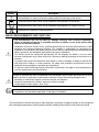
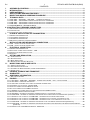
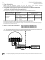
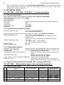
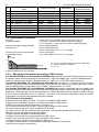
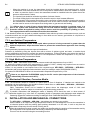
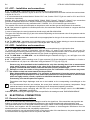
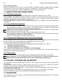
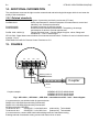
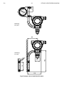
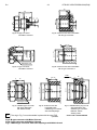
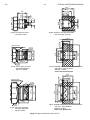
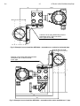
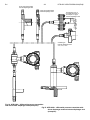
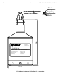
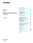
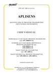
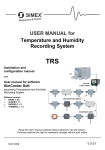
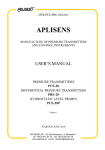
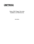
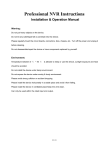
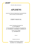
DTR.APC.APR.PROFIBUS.02(ENG) APLISENS MANUFACTURE OF PRESSURE TRANSMITTERS AND CONTROL INSTRUMENTS USER’S MANUAL INTRINSICALLY SAFE SMART PRESSURE TRANSMITTER type: APC-2000Ex/XX PROFIBUS PA INTRINSICALLY SAFE SMART DIFFERENTIAL PRESSURE TRANSMITTER type APR-2000Ex/XX PROFIBUS PA APR-2200Ex/XX PROFIBUS PA SMART PRESSURE TRANSMITTER type: APC-2000/XX PROFIBUS PA, APC-2000AL/PROFIBUS PA SMART DIFFERENTIAL PRESSURE TRANSMITTER type: APR-2000/XX PROFIBUS PA, APR-2000AL/PROFIBUS PA APR-2200AL/PROFIBUS PA SMART LEVEL PROBE type: SG.PROFIBUS PA Edition B1 WARSAW JANUARY 2015 APLISENS S.A. 03-192 Warszawa, ul. Morelowa 7 tel. +48 22 814 07 77; fax +48 22 814 07 78 www.aplisens.pl, e-mail: [email protected] Symbols used Symbol i Description Warning to proceed strictly in accordance with the information contained in the documentation in order to ensure the safety and full functionality of the device. Information particularly useful during installation and operation of the device. Information particularly useful during installation and operation of a type Ex device. Information on disposal of used equipment BASIC REQUIREMENTS AND SAFE USE - The manufacturer will not be liable for damage resulting from incorrect installation, - - - - failure to maintain the device in a suitable technical condition, or use of the device other than for its intended purpose. Installation should be carried out by qualified staff having the required authorizations to install electrical and pressure-measuring devices. The installer is responsible for performing the installation in accordance with these instructions and with the electromagnetic compatibility and safety regulations and standards applicable to the type of installation. The device should be configured appropriately for the purpose for which it is to be used. Incorrect configuration may cause erroneous functioning, leading to damage to the device or an accident. In systems with pressure transmitters there exists, in case of leakage, a danger to staff on the side where the medium is under pressure. All safety and protection requirements must be observed during installation, operation and inspections. If a device is not functioning correctly, disconnect it and send it for repair to the manufacturer or to a firm authorized by the manufacturer. In order to minimize the risk of malfunction and associated risks to staff, the device is not to be installed or used in particularly unfavourable conditions, where the following dangers occur: - possibility of mechanical impacts, excessive shocks and vibration; - excessive temperature fluctuation, exposure to direct sunlight; - condensation of water vapour, dust, icing. Installation of intrinsic safety versions should be performed with particular care, in accordance with the regulations and standards applicable to that type of installation. The manufacturer reserves the right to make changes (not having a negative impact on the operational and metrological parameters of the products) without updating the contents of the technical manual 1 DTR.APC.APR.FROFIBUS.02(ENG) CONTENTS APPENDIX Ex.PROFIBUS ............................................................................................................................. 2 INTRODUCTION............................................................................................................................................. 5 USER MATERIALS ........................................................................................................................................ 5 APPLICATIONS AND MAIN FEATURES ...................................................................................................... 5 IDENTIFYING MARKS. ORDERING PROCEDURE ...................................................................................... 5 TECHNICAL DATA. ....................................................................................................................................... 6 B1 I. 1. 2. 3. 4. 5. 5.1. APC-2000..., APR-2000..., APR-2200... - COMMON PARAMETERS ...................................................................................... 6 5.2. APC-2000... - MEASUREMENT RANGES AND METROLOGICAL PARAMETERS. ........................................................................... 6 5.3. APR-2000... - MEASUREMENT RANGES AND METROLOGICAL PARAMETERS. ........................................................................... 8 5.4. APR-2200... - MEASUREMENT RANGES AND METROLOGICAL PARAMETERS. ........................................................................... 8 5.5. SG PROFIBUS PA - TECHNICAL DATA. .......................................................................................................................... 9 6. CONSTRUCTION, PRESSURE CONNECTORS. ................................................................................................ 9 7. 8. 9. 6.1. MEASUREMENT PRINCIPLES, ELECTRONIC SYSTEM. ............................................................................................................... 9 6.2. CONSTRUCTION. .................................................................................................................................................................. 10 6.3. CASING, ELECTRICAL CONNECTIONS .................................................................................................................................... 10 PLACE OF INSTALLATION OF TRANSMITTERS ..................................................................................... 10 7.1. GENERAL RECOMMENDATIONS ............................................................................................................................................. 10 7.2. LOW AMBIENT TEMPERATURE. ............................................................................................................................................. 11 7.3. HIGH MEDIUM TEMPERATURE. ............................................................................................................................................. 11 7.4. MECHANICAL VIBRATION, CORROSIVE MEDIA. ...................................................................................................................... 11 INSTALLATION AND MECHANICAL CONNECTIONS .............................................................................. 11 8.1. APC... INSTALLATION AND CONNECTIONS ............................................................................................................................. 12 8.2. APR... INSTALLATION AND CONNECTIONS ............................................................................................................................. 12 ELECTRICAL CONNECTION ...................................................................................................................... 12 9.1. GENERAL RECOMMENDATIONS ............................................................................................................................................. 12 9.2. ELECTRICAL CONNECTIONS FOR APC..., APR...................................................................................................................... 13 9.3. PROTECTION FROM EXCESS VOLTAGE .................................................................................................................................. 13 9.4. EARTHING ............................................................................................................................................................................ 13 10. SETTING AND REGULATION ..................................................................................................................... 13 10.1. CONFIGURATION ................................................................................................................................................................ 13 10.2. DATA EXCHANGE ............................................................................................................................................................... 14 10.3. BASIC OPERATIONS ........................................................................................................................................................... 16 10.4. DIAGNOSIS AND TROUBLE-SHOOTING ................................................................................................................................ 17 11. INSPECTIONS AND SPARE PARTS. ......................................................................................................... 19 11.1. PERIODIC INSPECTIONS ...................................................................................................................................................... 19 11.2. UNSCHEDULED INSPECTIONS ............................................................................................................................................. 19 11.3. CLEANING THE DIAPHRAGM SEAL, OVERLOADING DAMAGE ................................................................................................ 19 11.4. SPARE PARTS. ................................................................................................................................................................... 19 12. 13. 14. PACKING, STORAGE AND TRANSPORT.................................................................................................. 19 GUARANTEE ............................................................................................................................................... 19 ADDITIONAL INFORMATION...................................................................................................................... 20 14.1. RELATED STANDARDS ........................................................................................................................................................ 20 15. FIGURES ...................................................................................................................................................... 20 FIG.1. APC-2000..., APR-2000..., APR-2200... TRANSMITTERS AND SG... LEVEL – BLOCK DIAGRAM. ....................................... 20 FIG.2. APC-2000... PRESSURE TRANSMITTER`............................................................................................................................ 21 FIG.3. ADDITIONAL EQUIPMENT FOR FITTING OF PRESSURE TRANSMITTERS. ................................................................................. 21 FIG.4. EXAMPLE: HOW TO INSTALL THE APC-2000... ................................................................................................................... 22 FIG.5. M-TYPE CONNECTOR WITH M20X1.5 THREAD ................................................................................................................... 23 FIG.6. P-TYPE CONNECTOR WITH M20X1.5 THREAD .................................................................................................................... 23 FIG.7. CM30X2-TYPE CONNECTOR WITH FLUSH DIAPHRAGM WITH M30X2 THREAD ...................................................................... 23 FIG.8. PROCESS CONNECTIONS G1/2” AND G1”. ......................................................................................................................... 24 FIG.9. APR-2000... DIFFERENTIAL PRESSURE TRANSMITTER WITH C TYPE VENTED COVERS. ....................................................... 25 FIG.10. APR-2000... DIFFERENTIAL PRESSURE TRANSMITTER WITH A SINGLE DIRECT DIAPHRAGM SEAL (EXAMPLE). ..................... 25 FIG.11. EXAMPLE: HOW TO INSTALL THE APR-2200... TRANSMITTERS WITH REMOTE DIAPHRAGM. ............................................... 26 FIG.12. EXAMPLE: HOW TO INSTALL THE APR-2000... TRANSMITTER ON A VERTICAL OR HORIZONTAL PIPE. .................................. 27 FIG.13. EXAMPLE: HOW TO INSTALL THE APR-2000... TRANSMITTER WITH A VALVE MANIFOLD TO A 2” PIPE. ................................. 27 FIG.14. APR-2200... DIFFERENTIAL PRESSURE TRANSMITTER WITH TWO REMOTE DIAPHRAGM SEALS(EXAMPLES). ...................... 28 FIG.15. APR-2200... DIFFERENTIAL PRESSURE TRANSMITTER WITH DIRECT DIAPHRAGM SEAL AND REMOTE DIAPHRAGM SEAL (EXAMPLES). ................................................................................................................................................................. 28 FIG.16. SMART LEVEL PROBE SG.PROFIBUS PA - DIMENSIONS.................................................................................................... 29 B1 2 DTR.APC.APR.FROFIBUS.02(ENG) I. APPENDIX Ex.PROFIBUS 1453 SMART PRESSURE TRANSMITTER type APC–2000Ex/XX PROFIBUS PA, SMART DIFFERENTIAL PRESSURE TRANSMITTERS type APR-2000Ex/XX PROFIBUS PA, APR-2200Ex/XX PROFIBUS PA, Ex VERSIONS 1. Introduction 1.1. This “Appendix Ex.PROFIBUS” applies only to transmitters of types APC-2000Ex/XX PROFIBUS PA, APR-2000Ex/ XX PROFIBUS PA, APR-2200Ex/XX PROFIBUS PA in Ex versions, marked on the rating plate as shown in 2.2 and denoted Ex in the Product Certificate. 1.2. The appendix contains supplementary information relating to the Ex versions of these transmitters. During installation and use of Ex transmitters, reference should be made to DTR.APC.APR.PROFIBUS(ENG) in conjunction with “Appendix Ex.PROFIBUS”. 2. Use of APC-2000Ex/XX PROFIBUS PA, APR-2000Ex/XX PROFIBUS PA, APR2200Ex/XX PROFIBUS PA transmitters in danger zones. 2.1. The transmitters are produced in accordance with the requirements of the following standards EN 60079-0:2012, EN 60079-11:2012, 2.2. The transmitters may operate in areas where there is a risk of explosion, in accordance with the rating of the explosion protection design: II 1/2G Ex ia IIB/ T5 Ga/Gb II 1/2G Ex ia IIB/ T4 Ga/Gb (Power supply Ui=17,5V)) FTZÚ 05 ATEX 0301 The transmitters may operate in FISCO systems. 2.3. Transmitter category and hazard areas. The category 1/2G, contained within the rating, means that the transmitter may be installed within a type 1 or 2 hazard zone. The APC-2000Ex/XX PROFIBUS PA, APR-2000Ex/XX PROFIBUS PA, APR-2200Ex/XX, PROFIBUS PA process connections may connect to a type 0 zone (see the diagram below for an example). Zone 0 Zone 1 or 2 Safe area Pressure transmitter or differential pressure transmitter 3. Identifying marks. Intrinsically safe transmitters must have a rating plate containing the information specified in paragraph 4 of DTR.APC.APR.PROFIBUS.02(ENG) and also at least the following: - CE mark and number of notified unit:, - designation of explosion protection design, certificate number values of parameters such as. Ui, Ii, Pi, Ci, Li marking of electrical and process connections year of manufacture mark B1 3 DTR.APC.APR.FROFIBUS.02(ENG) Appendix Ex.PROFIBUS 4. User information. Together with the transmitters ordered, the user will receive: User’s DTR.APC.APR.PROFIBUS(ENG) with Appendix Ex, and also the Product Certificate. Manual numbered 5. Permitted input parameters (based on data from the FTZÚ 05 ATEX 0301 certificate, and certification documentation.) Power supply with a “trapezial” or “rectangular” characteristic adapted to FISCO requirement. Rating of intrinsically safe power supplier (coupler) [Ex ia] IIB or [Ex ib] IIB Power conditions: Ui, Ii, Pi Li, Ci Ambient temperature range and temperature class Ui=15V Ii=0,380A Pi=5,32W Ci5nF, Li10H Ta65C T5 Standard version Ui=17,5V Ii=0,38A Pi=5,32W Ci5nF, Li10H Ta65C T4 Special version The protection level of power supplies with a “rectangular” characteristic is normally “ib”. The transmitter powered from such a supply is also a Ex device with protection level “ib”. In this case limit conditions of power supply that is voltage, current and power values of transmitter input signal are the same as for protection level “ia”. 6. How to connect Ex transmitters APC-2000Ex/XX PROFIBUS PA, APR-2000Ex/XX PROFIBUS PA, APR-2200Ex/XX PROFIBUS PA The transmitter and other devices in the measuring loop should be connected in accordance with the intrinsic-safety, explosion-safety regulations and FISCO models. PA- PA- PA+ PA+ Earthing terminal internal + _ Coupler Shield Screen i The display backlighting intrinsically safe transmitters is factory turned off and don’t allowed its to turn on. B1 4 DTR.APC.APR.FROFIBUS.02(ENG) Appendix Ex.PROFIBUS 7. Basic requirements for cable used to connect the transmitter to the power supply and measurement circuit. Load resistance Load inductance Load capacity Rc 15/km to 150/km, Lc 0,4mH/km to 1mH/km, Cc 45nF/km to 200nF/km, It is recommend to use shielded cable for types as below: Technotronic-bus O2YS(St)CY 1x2x1,0/2,6 mm produced by Technokabel SINEC 6XV1 830-5AH10 produced by SiemensAG SINEC 6XV1 830-3BH10 produced by SiemensAG 3079A produced by BELDEN. It is recommend to connect cable shield with earthing terminal of transmitter casing. Earthing terminal of transmitter casing connect with mass circuit or earth. It is not permitted to repair or otherwise interfere with the transmitter’s electrical circuits in any way. Damage and possible repair may be assessed only by the manufacturer or another authorized party. i Additional information about Profibus-PA networks and FISCO models can be found on: EN-60079-27 - Electrical apparatus for explosive gas atmospheres - Part 27: Fieldbus intrinsically safe concept (FISCO) and fieldbus non-incendive concept (FNICO) B1 1. 5 DTR.APC.APR.FROFIBUS.02(ENG) INTRODUCTION 1.1. This manual is intended for users of non-intrinsic-safe versions SG.PROFIBUS PA, APC-2000AL/PROFIBUS PA, APC-2000/XX PROFIBUS PA smart pressure transmitters and APR-2000AL/PROFIBUS PA, APR-2000/XX PROFIBUS PA, APR-2200AL/PROFIBUS PA smart differential pressure transmitters and intrinsic-safe versions APC-2000Ex/XX PROFIBUS PA smart pressure transmitters and APR-2000Ex/XX PROFIBUS PA, APR-2200Ex/XX PROFIBUS PA, smart differential pressure transmitters, containing the data and guidelines necessary to understand the functioning of the transmitters and how to operate them. It includes essential recommendations concerning installation and use, as well as emergency procedures. 1.2. The parameters and information specified for transmitters identified herein with the sign APC-2000..., APR-2000..., APR-2200..., also apply to transmitters showed in p.1.1 as well as all the variations differing by the type of the process terminals. 1.3. Information on the transmitter sizes and the method of installation apply to both, the intrinsic-safe and nonintrinsic-safe transmitters. 1.4. Technical data for the diaphragm seals and for the APC-2000..., APR-2000..., APR-2200... transmitters are contained in the catalogue cards “DIAPHRAGM SEALS”. 1.5. The transmitters comply with the requirements of EU directives as shown on the plate and with the relevant Declaration of Conformity. i 1.6. Additional data on APC-2000Ex/XX PROFIBUS PA, APR-2000Ex/XX PROFIBUS PA, APR-2200Ex/XX PROFIBUS PA transmitters in Ex versions covered by the EU-type test certificate number FTZÚ 05 ATEX 0301 is contained in the appendix designated DTR.APC.APR. Appendix Ex.PROFIBUS. During installation and use of the transmitters in Ex version, reference should be made to DTR.APC.APR.PROFIBUS PA in conjunction with Appendix Ex.PROFIBUS. 2. USER MATERIALS Together with the ordered transmitters, the user will receive: Product Certificate, Declaration of conformity, Copy of certificate – on request User’s Manual numbered: DTR.APC.APR.PROFIBUS.02(ENG) with Appendix Ex.PROFIBUS. User can find them at www.aplisens.pl 3. APPLICATIONS AND MAIN FEATURES 3.1. The APC-2000... smart pressure transmitter are designed to measure positive gauge pressure, vacuum pressure and absolute pressure of gases, vapours and liquids (including corrosive substances). Differential pressure transmitters type APR-2000..., APR-2200... are used to measure liquid levels in closed tanks, with static pressure of up to 25MPa or 32MPa for special versions and to measure differential pressure across constrictions such as filters and orifices. The SG.Profibus PA smart level probe is applicable to measure liquid levels in tanks, deep wells and in intermediate pumping stations, fermentation chambers, settling tanks etc. i 3.2. The APC-2000..., APR-2000..., APR-2200..., transmitters may be fitted with a range of types of process connectors, which enables them to be used in a variety of conditions such as thick or highly reactive media, high and low temperatures, etc. 4. IDENTIFYING MARKS. ORDERING PROCEDURE 4.1. Every transmitter carries a rating plate containing at least the following information: CE mark, numbers of notified institutions and designations of certificates obtained, name of manufacturer, type, factory number, basic range, min. set range, static pressure limit, output signal, power supply voltage. Version types and the method of specifying the desired product when ordering are described in the current “Information Cards” and the Catalogue. i 4.2. APC-2000..., APR-2000..., APR-2200..., transmitters in version: Ex approval have additional markings as described in Appendix Ex.PROFIBUS”. 4.3. The rating plates of transmitters of type APC-2000/XX PROFIBUS PA in versions compliant with the PED pressure directive contain the notified unit number 0062 next to the CE mark, as well as the designations of certificates number H1. B1 6 DTR.APC.APR.FROFIBUS.02(ENG) 4.4. The rating plates of transmitters of type APR-2200Ex/XX PROFIBUS PA in versions compliant with the PED pressure directive contain the notified unit number 0062 next to the CE mark, as well as the designations of certificates number H1. 5. TECHNICAL DATA. 5.1. APC-2000..., APR-2000..., APR-2200... - Common parameters 5.1.1. Electrical parameters Power supply for intrinsic-safe versions: in accordance with „Appendix Ex.PROFIBUS”. Power supply for non-intrinsic-safe versions: see fig.1 Current consumption: 14 mA Output parameters: Output signal: Digital communication signal Profibus-PA (according to EN 50170) PA function: Slave Physical lager: IEC61158-2 Transmission range: 31.25.kBit/s Modulation: Manchester II 5.1.2. Permitted environmental conditions Operating temperature range -40°C ÷ 85°C (ambient temperature) also for transmitters with display Operating temperature range for intrinsic-safe versions in accordance with “Appendix Ex.PROFIBUS”. Medium temperature range -40°C ÷ 120°C – direct measurement, over 120°C measurement with the use of a transmission tube or diaphragm seal to 100°C - for version compliant with the PED pressure directive Thermal compensation range -25º ÷ 80ºC, (-5º ÷ 65ºC for range – n°14 APC-2000...) (-40º ÷ 80ºC for special version APC-2000...) Relative humidity 0% ÷ 90% Vibration during operation max. 4g 5.1.3. Construction materials Diaphragm seal for APC-2000... Stainless steel 316L (00H17N14M2)(PED version) or Hastelloy C276 Diaphragm seal for APR-2000... Stainless steel 316L (00H17N14M2)(PED version) or Hastelloy C276 Sensing module Stainless steel 316L (00H17N14M2) Liquid filling the interior the sensing module Silicone oil, chemically inactive liquid for measurement of oxygen. Connectors for APC-2000... Stainless steel 316L (00H17N14M2) or Hastelloy C276 only for P, GP, CM30x2 C-type vented covers and connectors for APR-2000... Stainless steel 316L (00H17N14M2) Electronics casing High pressure cast of aluminium alloy, lacquered with chemical-resistant oxide enamel, colour yellow (RAL 1003). 5.1.4. Ingress Protection Rating of Case IP66, IP67 according to EN 60529 5.2. APC-2000... - Measurement ranges and metrological parameters. 5.2.1. Measurement ranges N 1. 2. 3. 4. 5. 6. 7. Nominal measuring range (FSO) 0...1000bar (0...100MPa) 0...300bar (0...30MPa) 0...160bar (0...16MPa) 0...70bar (0...7MPa) 0...25bar (0...2,5MPa) 0...7bar (0...0,7MPa) -1...7bar (-100...700kPa) Minimum set range 10bar 3bar 1,6bar 0,7bar 0,25bar 0,07bar 0,07bar (1MPa) (300kPa) (160kPa) (70kPa) (25kPa) (7kPa) (7kPa) Rangeability 100:1 100:1 100:1 100:1 100:1 100:1 114:1 Overpressure limit (without hysteresis) 1200bar (120MPa) 450bar (45MPa) 450bar (45MPa) 140bar (14MPa) 50bar (5MPa) 14bar (1,4MPa) 14bar (1,4MPa) B1 7 Nominal measuring range Minimum set range N (FSO) 8. 0...2bar (0...200kPa) 100mbar (10kPa) 9. 0...1bar (0...100kPa) 50mbar (5kPa) 10. -0,5...0,5bar (-50...50kPa) 50mbar (5kPa) 11. 0...0,25bar (0...25kPa) 25mbar (2,5kPa) 12. -100...100mbar (-10...10kPa) 20mbar (2kPa) 13. -15...70mbar* (-15...7kPa) 5mbar (0,5kPa) 14. 0...1,3bar abs (0...130kPa abs) 100mbar abs(10kPa abs) 15. 0...7bar abs (0...7MPa abs) 100mbar abs(10kPa abs) 16. 0...25bar abs (0...2,5MPa abs) 0,25bar abs (25kPa abs) 17. 0...70bar abs (0...7MPa abs) 0,7bar abs (70kPa abs) * - only for transmitters without diaphragm seal, DTR.APC.APR.FROFIBUS.02(ENG) Overpressure limit (without hysteresis) 20:1 4bar (400kPa) 20:1 2bar (200kPa) 20:1 2bar (200kPa) 10:1 1bar (100kPa) 10:1 1bar (100kPa) 17:1 0,5bar (50kPa) 13:1 2bar (200kPa) 70:1 14bar (1,4MPa) 100:1 50bar (5MPa) 100:1 140bar (14MPa) Rangeability 5.2.2. Metrological parameters Accuracy Long term stability max ± 0,075% for the basic range (0,16% for range 14) accuracy / 3 years (for the nominal measuring range) or ≤ 2 x accuracy / 5 years (for the nominal measuring range) max ± 0,002%(FSO)/1V max ± 0,05%(FSO)/10ºC max ± 0,1% FSO/10C for n°12, 13 ranges. max ± 0,25%(FSO) (max ± 0,4% FSO/10C for n°12, 13 ranges. Error due to supply voltage changes Thermal error Thermal error for the whole thermal compensation range Błąd podstawowy Accuracy Szerokość zakresu Set range nastawianego 0 – error for nominal measuring range (0...100%FSO) 1 - error for range (0...10%FSO) 1 = 2 x 0 Accuracy depending on the set range 5.2.3. - Metrological Parameters according to PED version. APC-2000/XX PROFIBUS PA, APC-2000Ex/XX PROFIBUS PA transmitters, in the PED Pressure Directive versions, are produced with a measurement range in the interval from –100 kPa to 40MPa gage, or from 0 to 40MPa absolute, with the overpressure up to 44 MPa. Temperature limit -40 ÷ 1000C (-40 ÷ 1500C with S-Mazut connector). APR-2000/XX PROFIBUS PA, APR-2000Ex/XX PROFIBUS PA transmitters, in the PED Pressure Directive versions, are produced with a measurement range in the interval from –100 kPa to 2,5MPa gage, with the static pressure 25MPa and the overpressure up to 27,5 MPa. Temperature limit -25 ÷ 1000C. APC-2000/XX PROFIBUS PA, APC-2000Ex/XX PROFIBUS PA pressure transmitters with the S-Mazut seal pressure connection, assembled with the PED version can be produced within the range–100 kPa to 10 MPa gage, or within the 0 - 10 MPa absolute, and the overpressure up to 11 MPa. Other parameters are as given in Tables 1, except that the ambient temperature error is 0.7 kPa/10ºC. The value of the pressure measurement range and related overpressure are given on rating plate and at Product Certificate. 5.2.4. Pressure Connectors. M-type connector with M20x1.5 thread – see figure 5a, available for PED version. P-type connector with M20x1.5 thread – see figure 6a, available for PED version. CM30x2-type connector with flush diaphragm – see figure 7a, G1/2 -type connector with G1/2” thread – see figure 8a, available for PED version. GP -type connector with G1/2” thread, available for PED version. CG1-type connector with G1” thread and flush diaphragm – see figure 8e, available for PED version. RM-type connector with M20x1.5 thread and radiator. RP-type connector with M20x1.5 thread and radiator. G1/4-type connector with G1/4 thread, available for PED version. 1/2"NPT -type connector with 1/2"NPT tread, available for PED version. R1/2-type connector with R1/2 tread, available for PED version. CG1/2-type connector with G1/2 tread and flush diaphragm, available for PED version other connection types by arrangement. B1 DTR.APC.APR.FROFIBUS.02(ENG) 8 5.3. APR-2000... - Measurement ranges and metrological parameters. 5.3.1. Measurement ranges N 1 2 3 4 5 6 7 8 9 Nominal measuring range (FSO) 0…70bar (0…7MPa) 0...16bar (0...1,6MPa) 0...2,5bar (0...250kPa) 0...1bar (0...100kPa) 0...0,25bar (0...25kPa) -0,5…0,5bar (-50…50kPa) -100...100mbar (-10...10kPa) -5...70mbar (-0,5...7kPa) -20...20mbar (-2...2kPa) Minimum set range 7bar 1,6bar 0,2bar 50mbar 10mbar 0,1bar 10mbar 4mbar 2mbar (700kPa) (160kPa) (20kPa) (5kPa) (1kPa) (10kPa) (1kPa) (0,4kPa) (0,2kPa) Rangeability 10:1 10:1 12,5:1 20:1 25:1 10:1 20:1 18:1 20:1 Overpressure limit Static pressure limit 250, 320bar (40bar for P-type connector) (250bar for version compliant with the PED pressure directive) 20 bar (10 bar for PED version) 5.3.2. Metrological parameters Accuracy Long term stability Error due to supply voltage changes Thermal error ± 0,075% (FSO) for the APR-2000ALW nominal range ± 0,01% (FSO) for the APR-2000ALW nominal range (range n°9) accuracy / 3 years ± 0,002%(FSO)/1V ± 0,05%(FSO)/10ºC for range n° 1…8 ± 0,08%(FSO)/10ºC for range n° 9 Thermal error for the whole thermal compensation range Zero shift error for static pressure* ± 0,3%(FSO) ± 0,08 % (FSO)/10bar (for range n°2, 7) ± 0,01 % (FSO)/10bar (for range n°3, 4, 5, 6) ± 0,03 % (FSO)/10bar (for range n°1, 7, 8) Cut-off on radical characteristic curve up to10% of flow. *) zeroing in static pressure conditions with zero differential pressure eliminate this error 5.3.3. Pressure Connectors APR-2000...- without diaphragm seals – C-type connector to mount together with a valve manifold see fig.9. APR-2000...- with single direct diaphragm seal – as in the example (fig.10) or with other diaphragm seals in accordance with catalogue cards “DIAPHRAGM SEALS”. 5.4. APR-2200... - Measurement ranges and metrological parameters. 5.4.1. Measurement ranges Nominal range (FSO) -160...160 mbar -0,5...0,5 bar -1,6...2 bar -1,6...16 bar Minimum set range 0,1 mH2O 0.5 mH2O 1,5 mH2O 1bar Maximum configurable range dependent Vertical spacing Static on the actual vertical spacing of of diaphragm pressure limit seals. diaphragm seals. (m) [1,6+( vertical spacing of sealsx94)]mH2O 40bar 1,7m [5+(vertical spacing of sealsx1,04)]mH2O 40bar 6m [20+(vertical spacing of sealsx1,04)]mH2O 40bar 15m 16bar 40bar 15m 5.4.2. Metrological parameters Accuracy Thermal error Thermal error for the whole thermal compensation range Zero shift error for static pressure Error related to changes of Usup. Additional errors due to effects of sealing i ± 0,1% (FSO) ± 0,08 % (FSO) / 10C ± 0,3 % (FSO) ± 0,08 % (FSO) / 1MPa ± 0,002 % (FSO) / V see catalogue cards “DIAPHRAGM SEALS”. The maximum vertical diaphragm seal spacing shown in the table applies to level measurement, ensuring that it is possible to set the zero point of the transmitter when the tank is empty. For measurements of density or phase boundaries (in the sugar and chemical industries and in refineries) the vertical spacing of the diaphragm seals can be larger. B1 9 DTR.APC.APR.FROFIBUS.02(ENG) 5.4.3. Pressure Connectors - diaphragm seals – see catalogue cards “DIAPHRAGM SEALS”. 5.5. SG PROFIBUS PA - TECHNICAL DATA. 5.5.1. Measurement ranges Nominal measuring range (FSO) 0...10 mH2O 0...100 mH2O Minimum set range 0,8 mH2O 8 mH2O Max. range (measurement limit) -1...11,5 mH2O -5...115 mH2O Overpressure limit (without hysteresis) 100 mH2O 700 mH2O 5.5.2. Metrological parameters Accuracy ± 0,1% for nominal range ± 0,3% for range: 0 … 10% FSO Long term stability Thermal error Thermal error in the whole compensation temp. range 0,1% (FSO) for 2 years < 0,08% (FSO)/10ºC max 0,25%(FSO) 5.5.3. Electrical parameters Power supply (from DP/PA coupler): Curent consumption: 10,5 ÷ 28VDC (Black wires) (any direction of polarization), blue - shield 14 mA Output parameters Output signal: PA function: Physical layer: Transmission rate: Modulation: Digital communication signal Profibus-PA (according to EN 50170) Slave IEC61158-2 31.25.kBit/s Manchester II 5.5.4. Permitted environmental conditions Medium temperature range: -30°C ÷ 80°C for basic range 0 … 10mH2O -30°C ÷ 50°C for basic range 0 … 100mH2O -25°C ÷ 80° Thermal compensation range: i The medium must not be allowed to freeze in the immediate vicinity of the probe 5.5.5. Construction materials Electronics casing Diaphragm Cable shield: Additional cable shield: Stainless steel 316L (00H17N14M2) Stainless steel 316L (00H17N14M2) Polyurethane Teflon (fitted by arrangement) 6. CONSTRUCTION, PRESSURE CONNECTORS. 6.1. Measurement Principles, Electronic System. APC-2000... electronic pressure transmitters and APR-2000..., APR-2200... electronic differential pressure transmitters work by converting changes in the resistance of a piezoresistant bridge, which are proportional to the pressure difference being measured, into a standard current signal. The active sensing element is a silicon diaphragm with in-diffused piezoresistors, separated from the medium by a sealing diaphragm and manometric fluid. B1 10 DTR.APC.APR.FROFIBUS.02(ENG) 6.2. Construction. The main components of the smart pressure transmitter are the sensing module, in which the pressure signal is converted into a non-uniformized signal, and the electronic system, which converts the signal from the sensing module into a PROFIBUS PA output signal. 6.2.1. In the APC-2000... transmitters the pressure connectors may be attached to the sensing module as in fig.5a, 6a, 7a, 8 and other. They are equipped with a diaphragm separating the internal part of the head from the medium. 6.2.2. In the APR-2000... transmitters, the sensing module has two P-type connectors, or C-type connecting covers for installation on a valve manifold (fig.9). 6.2.3. For measuring the pressure of dense, chemically reactive or hot media, the transmitter may be additionally fitted with various types of diaphragm seal depending on the type of medium and the conditions in which measurement is carried out (see catalogue cards “Diaphragm Seals). The diaphragm seal transmits the pressure obtained from the medium. The pressure is transmitted via a manometric fluid which fills the space between the diaphragm of the seal and the diaphragm of the sensing module. In the case of remote diaphragm seals, pressure is transmitted via a capillary linking the transmitter’s sensing module to the diaphragm seal. The construction of the seals depends on the medium properties and operating conditions for which they are intended. Technical data relating to the diaphragm seals’ dimensions and operating conditions can be found in catalogue cards “DIAPHRAGM SEALS”. 6.2.4. The APR-2000... transmitters may be fitted with an single direct diaphragm seal, mounted on the “+” pressure input of the sensing module, while the “–” input is a ¼NPT socket (fig.10). i The APR–2200... transmitter is fitted with two diaphragm seals and can be produced in two versions: with one direct diaphragm seal and one remote diaphragm seal (fig.15); with two remote diaphragm seals (fig.14). 6.3. Casing, Electrical Connections The APC-2000..., APR-2000..., APR-2200... transmitters have a casing made from high-pressure cast of aluminium alloy, giving o IP-65 protection. The housing is provided with two screwed-on covers: one closed with a cavity and a feeder box, the other cover can have a glass allowing to use a point display, the display has a 90° turning angle, the turn of the housing in relation to the sensor from 0 to 355°, the direction of the cable input can be chosen. 6.3.1. The transmitter is provided with a built-in LCD display. Using the specific manufacturer’s commands it is possible to perform the following operations on the display: ● display the output value in percents or in the user’s units (in accordance with the current configuration, i.e. range, suppression, conversion curve), ● rotate the displayed values by 180° ● normal display and display in the negative. ● adjust brightness ● change the position of the decimal point The LCD display includes a graphic display allowing to illustrate the measured value in percentage of the set output range. The not intrinsic-safe versions of transmitters APC-2000..., APR-2000..., APR-2200... are provided with a display with additional highlighting function. The function can be switch ON and OFF by the user using switch no. 1 on the display panel. ON position means that the highlight function is OFF. 7. PLACE OF INSTALLATION OF TRANSMITTERS 7.1. General recommendations 7.1.1. The smart pressure transmitter and differential pressure transmitter can be installed both indoors and outdoors. It is recommended that transmitters intended for outdoor use be placed in a box or under cover. 7.1.2. The place of installation should be chosen in such a way as to allow access to the device and to protect it from mechanical damage. In planning the installation of the transmitter and configuration of the impulse lines, attention should be paid to the following requirements: i - The impulse lines should be as short as possible, with a sufficiently large cross-section, and free of sharp bends, in order to prevent blockages; B1 11 - i - - DTR.APC.APR.FROFIBUS.02(ENG) Where the medium is a gas, the transmitters should be installed above the measuring point, so that condensation flows down towards the site of the pressure measurement; where the medium is a liquid or where a protective liquid is used, the transmitters should be installed below the place where the pressure measurement is taken; The impulse lines should be inclined at a gradient of at least 10cm/m; The levels of filling liquid in the impulse lines should be equal or kept constant difference, The configuration of the impulse lines and the valve connection system should be chosen with regard to the measurement conditions and to requirements such as the need to reset the transmitters in position and the need for access to the impulse lines during water or gas removal and flushing. 7.1.3. Where there is a risk of heavy objects hitting the instrument (resulting, in extreme cases, in a part of the system with transducers being torn off and medium leakage), appropriate means of protection should be applied for safety reasons and to avoid the possibility of sparkling or other, more appropriate location should be selected for the transmitter. 7.1.4. Attention should also be paid to possible installation faults which may lead to measurement errors, such as connections which are not tight, sediment blockage in lines which are too narrow, gas bubbles in a liquid line or liquid column in a gas line etc. 7.2. Low Ambient Temperature. When the solidification point of the liquid whose pressure is being measured is greater than the ambient temperature, steps should be taken to protect the measurement apparatus from freezing effects. This is particularly important in the case open-air installations. Protection is obtained by filling the impulse lines with a mixture of ethylene glycol and water, or another liquid whose solidification point does not exceed the ambient temperature. Thermal insulation can protect the casing of the transmitter and lines only from brief exposure to low temperatures. Where the temperature is very low, the transmitter and impulse lines are should be heated. 7.3. High Medium Temperature. The APC..., APR... transmitters may be used to measure media with temperatures of up to 120°C. To protect the sensing module from temperatures in excess of 120ºC, suitably long impulse lines are used to disperse the heat and to lower the temperature of the module. Where it is not possible to use impulse lines of the required length, APC-2000..., APR-2000..., APR-2200... transmitters with remote diaphragm seals should be used (see catalogue cards “DIAPHRAGM SEALS”). For probes SG.PROFIBUS PA does not exceed media's temperatures specified in p.5.5.4. Data as per Appendix Ex.PROFIBUS apply for the Ex version (the temperature of the electronic subassembly cannot exceed +65°C). 7.4. Mechanical Vibration, Corrosive Media. 7.4.1. The transmitter should be installed in a place which is free of vibrations. If vibrations are carried to the transmitter via the impulse lines, use should be made of elastic lines or a APC-2000..., APR-2000..., APR-2200... transmitters with a remote diaphragm seal. 7.4.2. Transmitters should not be installed in places where the diaphragm, made of 316L steel 00H17N14M2), would be subject to corrosion by the medium being measured If possible, transmitters with diaphragms made of Hastelloy C276 should be used, or other means of protection applied (e.g. in the form of a separating liquid) or transmitters with diaphragm seals adapted for measuring aggressive mediums according to catalogue cards “DIAPHRAGM SEALS”) should be used. 8. i INSTALLATION AND MECHANICAL CONNECTIONS The APC-2000..., APR-2000..., APR-2200... transmitters can operate in any position. When installed on an object with a high-temperature medium, it is advantageous to mount the transmitter in a horizontal position with the packing gland pointing downwards or to the side, in such a way that the transmitter is kept away from the stream of rising hot air. When the measurement range is small, the reading can be affected by the position of the transmitter and by the configuration of the impulse lines and the way in which they are filled with liquid. This error can be corrected using the zero-setting function. B1 12 DTR.APC.APR.FROFIBUS.02(ENG) 8.1. APC... Installation and connections 8.1.1. The APC-2000... transmitters can be mounted directly on rigid impulse lines. Where connectors are used as in fig.5a, 6a and 7a, it is recommended that connection sockets be used as shown in fig.5b, 6b, 7b or 7c. It is recommended that sockets labeled “Socket CG1” and „Socket CG1/2” Fig.8 are used for CG1 and CG1/2 connections, respectively. Besides, there are adapters for standard DIN50, (DIN40, DIN25, Clamp2”, Clamp1,5”, Clamp1”) type connections provided for readouts carried out in aseptic conditions using transmitters with CM30x2 connection. There are seals provided for every transmitter with P, CM30x2, CG1, CG1/2 and GP type connections. The material of the seal is selected based on the pressure value and the type and temperature of the medium. 8.1.2. If the pressure is applied via a flexible plastic tube, the transmitter should be mounted on a support with Red Ø6-M reduction. In case of metal pipes, the used connections should comply with PN-82/M-42306. The types of the impulse tubes (Fig.3) are to be selected depending on the measured value of the pressure and the medium temperature. 8.1.3. Tighten the transmitter in the socket with a torque appropriate for the type of the used seal and the measured pressure. 8.1.4. The APC-2000... transmitter can be installed using a universal “AL” holder allowing to mount the transmitter in any position on the support or a horizontal or vertical pipe Ø35... Ø65 (Fig.4). 8.2. APR... Installation and connections 8.2.1. The APR 2000/XX PROFIBUS PA transmitters can be mounted directly on rigid impulse lines. To connect the basic versions of transmitters, with two M20 x 1.5 stubs (P-type connector), one can use (for example) straight connecting elements with nuts (type C). If elastic impulse lines are used for connection purposes, the transmitter should be additionally fastened to a pipe, panel or supporting construction. 8.2.2. The APR-2000... and APR-2200... can be installed using the Fastener ø25 (fig.11.) on a ø25 pipe or on a flat surface using an angle bracket. 8.2.3. The APR-2000... with connecting cover (C-type connector) (fig.9) are designed for installation on 3-valve or 5-valve manifolds to a 2” pipe or to a flat surface using an fastener “C-2” (fig.12) or (fig.13). Pressure may be transmitted to the installed device only after checking that it has a measurement range which properly corresponds to the value of the measured pressure, that gaskets have been properly selected and fitted, and the connector has been properly screwed tight. Attempts to undo the screws or fixing connector pipes on a transmitter under pressure may cause the medium to leak and create hazards for the personnel. When disassembling the transmitter, it is necessary to disconnect it from the process pressure or bring the pressure to atmospheric level, and to take particular care and precautions in case of media which are highly reactive, caustic, explosive or otherwise hazardous to personnel. If necessary, rinse out this part of the system. Transmitters with flange diaphragm seals are to be installed on the corresponding counterflanges on the facility. It is recommended that the user matches the screw joints material to the pressure, temperature, flange material and seal to ensure tightness of the flange joint in the expected operating conditions.. Coarse-threaded screws complying with ISO 261 are to be used for flanges used in the APC-2000..., APR-2000..., APR-2200... transmitters. Additional data concerning the diaphragm seals are specified in the catalogue cards “DIAPHRAGM SEALS”. i 9. ELECTRICAL CONNECTION 9.1. General recommendations 9.1.1. It is recommended that twisted pair cabling be used for the signal lines. If the transmitter and signal line are subject to a large amount of electromagnetic interference, then screened twisted pair cable should be used. The signal wires should not run alongside network power supply cables or near to large electrically-powered devices. The devices used together with the transmitters should be resistant to electromagnetic interference from the transmission line in accordance with compatibility requirements. It is also beneficial to use anti-interference filters on the primary side of the transformers, the power supplies used for the transmitters and apparatus used in conjunction with them. B1 13 i DTR.APC.APR.FROFIBUS.02(ENG) 9.1.2. Wet or damp inside can cause the transmitter to fail. Where the isolation of the wires in the packing gland is ineffective (for example, when single wires are used) the opening of the gland should be carefully sealed with an elastic sealing compound to obtain IP65 ingress protection. It is useful to form the segment of the signal wire leading to the M20x1,5 packing gland into a protective loop to prevent condensation from running down in the direction of the gland. 9.2. Electrical connections for APC..., APR... The transmitters should be connected as shown in figure.1. The APC-2000 is two-wired transmitter with PROFIBUS-PA output. Before connecting the device be sure power supply is turned off. To connect device to Profibus-PA network you should: turn off power supply unscrew the cover insert the cables through the cable entry connect cables to the adequate terminals -P,+P (reversed polarity has no effect on operations) connect the screen to the internal terminal screw down the cover turn on power supply 9.3. Protection from excess voltage 9.3.1. The transmitters may be in danger from excess voltage caused by connection faults or atmospheric electrical discharge. Protection from excess voltage between the wires of the transmission line is provided by transil diodes installed in all types of transmitter (see the table, column 2). In order to protect against excess voltage between the transmission line and the casing or earth (not prevented by the diodes connected between the transmission wires), additional protection is provided in the form of plasma surge arresters or transil diodes (see the table, column 3). In the case of unprotected transmitters, may be used external protective device. When the transmission lines are long, it is advantageous to use one protective device near the transmitter (or inside it), and another near entry points to other devices used in conjunction with it. Devices used to protect transmitters: 1 2 3 Type of Protection between wires (transil Protection between wires and earth and/or casing – type of transmitter diodes) – permitted voltage protection, permitted voltage Plasma surge arresters-100V DC (Not applicable to Ex version). APC..., APR... 36V DC 9.3.2. When excess voltage protection is used, the voltage in the protective elements must not exceed the maximum permitted values given in columns 2 and 3 of the table. i The insulation test voltages (500V AC or 750V DC) given in 5.1.1 refer to transmitters without the protective devices described in 9.3.2. Such protection is not used in Ex versions of transmitters. 9.4. Earthing The transmitters are fitted with internal and external earth terminals. 10. SETTING AND REGULATION 10.1. Configuration 10.1.1. Introduction The APC-2000..., APR-2000..., APR-2200... transmitter and SG... probe is a Profibus-PA network device builted in accordance with “PROFIBUS-PA Profile for Process Control Devices ver. 3.0” document. The configuration is entry of metrological and identification parameters into the transmitter’s memory. The basic metrological parameters are: start and end point of the set range, measurement units, time constant and conversion characteristic (linear or radical). All available parameters, including identification parameters, are collected in table and show in section 10.2.1. The APC-2000..., APR-2000..., APR-2200... transmitter and SG... probe can be configured with the software professional tools such a PDM, Commuwin II or any DTM/FDT tool (e.g. FieldCare). B1 DTR.APC.APR.FROFIBUS.02(ENG) 14 10.1.2. Setting the device address The APC-2000..., APR-2000..., APR-2200... transmitter and SG... probe has no hardware address switch. Address can be changed only with software tools such a PDM, Commuwin II, or FieldCare. 10.1.3. Plik GSD GSD file contains basic descriptions of device properties, e.g. the supported transmissions rates, type, and format of output data, supported extended functions. GSD file is required by network design tool and allow to connect the transmitter to network in proper way. The general GSD file for pressure transmitter with profile rev. 3 can be used for APC-2000..., APR-2000..., APR-2200... transmitters. The general GSD file can be found on the PNO web pages www.profibus.com (PA039700.gsd file). 10.1.4. Configuration software Full configuration of the APC-2000..., APR-2000..., APR-2200... transmitter and SG... probe can be done with Siemens PDM (Process Device Manager) tool. APLISENS delivers appriopriate EDD library for using with PDM tool. To install the library, the PDM DeviceInstaller must be used. All standard and block parameters can be configured by Endress+Hauser Commuwin II. They are accessible via appropriate Commuwin II operating matrixes. Any DTM/FDT tools can be used to configure standard and block parameters. 10.1.5. Ident Number The APC-2000..., APR-2000..., APR-2200... transmitters and SG... probe uses Universal Transmitter ID_Number with One Analog Input Function Block built according to “PROFIBUS-PA Profile for Process Control Devices ver. 3.0” document. This number is 9700h. 10.2. Data Exchange 10.2.1. Transmitter block model The APC-2000..., APR-2000..., APR-2200... transmitter and SG... probe is a compact device built according to Profibus Pressure Transmitter Profile rev. 3. The APC-2000..., APR-2000..., APR-2200... transmitter and SG... probe contains tree blocks: one Physical Block (PB), one Function Block (FB), and one Transmitter Block (TB). Function Block is an Analog Input Function Block (AI). All parameters are accessed via slot and relative index. All blocks has its own standard parameters, block parameters, and optionally manufacturer specific parameters. 141 - absolute address of Physical Block, from which computed are relative indexes in this block. 16 - absolute address function Block, from which computed are relative indexes in this block. 63 - absolute address transmitter Block, from which computed are relative indexes in this block. Additional information about block models and parameters can be found on „PROFIBUS-PA Profile for Process Control Devices Version 3.0, October 1999”. The APC-2000..., APR-2000..., APR-2200..., SG... parameters are gathered in tables below. Standard Parameters Storage Object Relative Data type Parameter type type index 0. 1. 2. 3. 4. 5. 6. 7. 8. BLOCK_OBJECT ST_REV TAG_DESC STRATEGY ALERT_KEY TARGET_MODE MODE_BLK ALARM_SUM BATCH* record simple simple simple simple simple record record structure size Access DS-32 unsigned 16 octet string unsigned 16 unsigned 8 unsigned 8 DS-37 DS-42 DS-67 C N S S S S D D S 20 2 32 2 1 1 3 8 10 r r r,w r,w r,w r,w r,w r r,w Object type Data type Storage type size Access simple simple simple simple simple simple simple visible string visible string unsigned 16 visible string visible string octet string octet string Cst Cst Cst Cst Cst D Cst 16 16 2 16 16 4 4 r r r r r r r * - parameter BATCH is accessible in Function Block (FB) only. Physical Block Parameters (PB) Relative Parameter index 8 9 10 11 12 13 15 SOFTWARE_REVISION HARDWARE_REVISION DEVICE_MAN_ID DEVICE_ID DEVICE_SER_Num DIAGNOSIS DIAGNOSIS_MASK B1 DTR.APC.APR.FROFIBUS.02(ENG) 15 17 18 19 20 21 22 24 DEVICE_CERTIFICATION WRITE_LOCKING FACTORY_RESET DESCRIPTOR DEVICE_MESSAGE DEVICE_INSTALL_DATE IDENT_NUMER_SELECTOR Analog Input Function Block Parameters (FB) Relative Parameter index 10 11 12 13 14 16 19 21 23 25 27 34 35 36-44 45 46 OUT PV_SCALE OUT_SCALE LIN_TYPE CHANNEL PV_TIME ALARM_HYS HI_HI_LIM HI_LIM LO_LIM LO_LO_LIM SIMULATE OUT_UNIT_TEXT Reserved by PNO USER_RERANGE_FACTOR CONTROL_MODES Transmitter Block Parameters (TB) Relative Parameter index 8 9 10 11 12 13 14 15 16 17 18 19 20 27 28 33 37 38 39 40 41 42 43 44 47 48 SENSOR_VALUE SENSOR_HI_LIM SENSOR_LO_LIM CAL_POINT_HI CAL_POINT_LO CAL_MIN_SPAN SENSOR_UNIT TRIMMED_VALUE SENSOR_TYPE SENSOR_SERIAL_NUMBER PRIMARY_VALUE PRIMARY_VALUE_UNIT PRIMARY_VALUE_TYPE TEMPERATURE TEMPERATURE_UNIT LIN_TYPE FLOW_LIN_SQRT_POINT TAB_ACTUAL_NUMBER TAB_ENTRY TAB_MAX_NUMBER TAB_MIN_NUMBER TAB_OP_CODE TAB_STATUS TAB_X_Y_VALUE MAX_TEMPERATURE MIN_TEMPERATURE simple simple simple simple simple simple simple visible string unsigned 16 unsigned 16 octet string octet string octet string unsigned 8 Cst N S S S S S 32 2 2 32 32 16 1 r r,w r,w r,w r,w r,w r Object type Data type Storage type size Access record array record simple simple simple simple simple simple simple simple record simple DS-33 2*float DS-36 unsigned 8 unsigned 16 float float float float float float DS-50 octet string D S S S S S S S S S S S S 5 8 11 1 2 4 4 4 4 4 4 6 16 r r,w r,w r,w r,w r,w r,w r,w r,w r,w r,w r,w r,w array array 2*float unsigned 8 S S 8 6 r,w r,w Storage type size Access D N N S S N S D N N D S S D S S S N D N N D D D N N 4 4 4 4 4 4 2 5 2 4 5 2 2 5 2 1 4 1 1 1 1 1 1 8 4 4 r r r r,w r,w r r,w r r r r r,w r,w r r r,w r,w r r,w r r r,w r r,w r r Object type simple simple simple simple simple simple simple record simple simple record simple simple record simple simple simple simple simple simple simple simple simple array simple simple Data type float float float float float float unsigned 16 DS-33 unsigned 16 unsigned 32 DS-33 unsigned 16 unsigned 16 DS-33 unsigned 16 unsigned 8 float unsigned 8 unsigned 8 unsigned 8 unsigned 8 unsigned 8 unsigned 8 float float float B1 16 DTR.APC.APR.FROFIBUS.02(ENG) D – dynamic, the value is calculated by the block or read from another block S – static, non-volatile and changing the parameter increase the static revision counter ST_REV N – non-volatile parameter which must be remembered through a power cycle, but which is not under the static update code Cst – constant, the parameter doesn't change in a device 10.2.2. Cyclic communication In the cyclic data exchange mode APC-2000..., APR-2000..., APR-2200... transmitter sends primary measured value and one byte of related status. Primary value is four byte long and is transmitted as an IEEE 754 floating point number. The related status is transmitted on the last byte and corresponds to transmitter state and measurement validity. 10.2.3. Acyclic communication Profibus DP Master Class 2 and appropriate software tool are needed to access all the transmitter parameters with acyclic communication. Acyclic communication is mainly used to configure the device, but reading primary value and status can be also possible. 10.3. Basic Operations 10.3.1. Calibration The maximum range of absolute or differential pressure which the transmitter can measure is called the “basic range” (for specifications of basic ranges see. 5.2.1., 5.3.1., 5.4.1.). The width of the basic range is the difference between the upper and lower limits of the basic range. To calibrate transmitter exactly to measuring range two parameters should be used: CAL_POINT_LO and CAL_POINT_HI. The transmitter may be set to any range within the basic range of pressure values, subject to the restrictions set out in the table in section 5.2.1., 5.3.1., 5.4.1. To calibrate APC-2000..., APR-2000..., APR-2200..., transmitter should be used Profibus DP Master Class 2 and professional software tool (PDM, Commuwin II, FieldCare). The highest accuracy is obtained when the value of parameter CAL_POINT_LO corresponds to the SENSOR_LO_LIM, and the parameter CAL_POINT_HI corresponds to the SENSOR_HI_LIM. The difference between CAL_POINT_LO and CAL_POINT_HI can not be lower then the value of parameter CAL_MIN_SPAN. In addition parameters CAL_POINT_LO and CAL_POINT_HI can not be lower than parameter SENSOR_LOW_LIM and higher then SENSOR_HI_LIM. All calibration parameters unit derives from SENSOR_UNIT. All calibration parameters are located in the Pressure Transducer Block (TB). 10.3.2. Primary value unit changing The APC-2000..., APR-2000..., APR-2200... transmitter can operate with various pressure units of PRIMARY_VALUE. A new unit can be set with PRIMARY_VALUE_UNIT parameter and will be displayed on the LCD indicator. Default value of PRIMARY_VALUE_UNIT parameter is kPa. All the APC-2000..., APR-2000..., APR-2200... transmitter units of process value are gathered in the table below: PV_Units Pa kPa MPA atm PV_Units torr psi bar mbar PV_Units in H2O in Hg ft H2O mm H2O PV_Units mm Hg g/cm2 kg/cm2 in H2O (4oC) PV_Units mm H2O (4oC) 10.3.3. Output scaling Analog Input Function Block contains two scaling parameters PV_SCALE and OUT_SCALE. Scaling is change of out pressure value depending on limit value PV_SCALE and OUT_SCALE. Scaling principle show as formula below: Pout = (Pin – OUT_SCALE_LOWER VALUE)x(OUT_SCALE_LOWER VALUE - OUT_SCALE_LOWER VALUE) (PV_UPPER_SCALE_VALUE - PV_LOWER_SCALE_VALUE) + OUT_SCALE_LOWER VALUE B1 17 DTR.APC.APR.FROFIBUS.02(ENG) Parameter PV_SCALE is used to make conversion of the Process Variable into percent using the high and low scale values. The engineering unit of PV_SCALE high and low scale values are direct related to the PV_UNIT of the configured Transducer Block. The PV_SCALE high and low scale values follow the changes of the PV_UNIT of the related Transducer Block automatically, i.e. a change of the Transducer Block PV_UNIT causes no bump at OUT from AI. The function block parameter OUT_SCALE contains the values of the lower limit and upper limit effective range, the code number of the engineering unit of Process Variable and the number of digits on the right hand side of the decimal point. After installation, the transmitter’s zero-point may drift and require adjustment. This applies particularly in cases where the measurement range is small, where the impulse lines are filled with a separating liquid or where APC-2000..., APR-2000..., APR-2200... transmitters are used with remote diaphragm seals. This error can be eliminated by changing of the parameter PV_LOWER_RANGE_VALUE. This error can be eliminated by zeroing the transmitter in static pressure conditions with zero differential pressure. 10.3.4. Manufacturer specific parameters There are only two manufacturer specific command in the APC-2000..., APR-2000..., APR-2200... pressure transmitter (software rev. 5). Both of them concerns the LCD indicator handling and are located in Analog Input Function Block with indexes 45 and 46. USER_RERANGE_FACTOR Parameter (index 45) contains two items: User_Rerange_Shift: Shift PV (Primary Value) User_Rerange_Amplification: Amplification PV This two parameters can be used to shift and amplify displaying value when LCD indicator is in the USER_RERANGE_MODE (set by Meter_Display_Variable parameter of CONTROL_MODES command). CONTROL_MODES Parameter (index 46) contains six items: Local_Keys_Mode_Control_Codes: Meter_Information_Configuration: Meter_Display_Mode: Meter_Display_Electronics_Bias_Control: Meter_Display_Variable: Meter_Display_Variable_Decimal_Point: Enable or disable local configuration keys control: Enabled Disabled Local configuration works in HART transmitters only. Set the LCD configuration: Not installed (LCD is OFF) Integral LCD (LCD is ON) Configuration will be changed after transmitter reset! Set LCD display mode: normal, right rotation normal, left rotation reverse, right rotation reverse, left rotation Set the LCD bias control, values: 0..31 Set the displayed value: pressure percent of range user rerange Set the number of digits on the right hand side of the decimal point 10.4. Diagnosis And Trouble-Shooting If the APC-2000..., APR-2000..., APR-2200... pressure transmitter detects an error or warning, the appropriate status code is transmitted with cyclic communication. If the APC-2000..., APR-2000..., APR-2200... transmitter detects a hardware problem, the appropriate error code and service information is displayed on the LCD indicator. B1 DTR.APC.APR.FROFIBUS.02(ENG) 18 10.4.1. Codes of Errors and Warnings Last byte of cyclic data exchange contains the status byte. The following status codes are supported by APC-2000..., APR-2000..., APR-2200... transmitters: Status Dec Hex 0 64 128 0 40 80 Gr 27 0 0 1 Gr 26 0 1 0 QS 25 Substatus QS QS 24 23 QS 22 Limits Qu Qu 21 20 Bad Uncertain Good Bit meanings at substatus = bad Status Substatus QS QS Dec Hex Gr Gr QS QS 0 00 0 0 0 0 0 0 0 00 0 0 0 0 1 1 0 00 0 0 0 1 0 0 0 00 0 0 0 1 1 1 Limits Qu Qu Non specific Transmitter broken Sensor broken Transmitter unavailable (out of service) Bit meanings at substatus = good Status Substatus Limits Dec Hex Gr Gr QS QS QS QS 128 80 1 0 0 0 0 0 Qu Qu OK 128 8C 1 0 0 0 1 1 warning 128 88 1 0 0 0 1 0 Critical alarm Limit bits meanings Status Gr Substatus Gr QS QS QS Limits Dec Hex Qu Qu +0 +00 QS 0 0 OK +1 +01 0 1 Below limit +2 +02 1 0 Above limit +3 +03 1 1 Constant value 10.4.2. Simulation With Profibus DP Master Class 2 and appropriate software it is possible to set APC-2000..., APR-2000..., APR-2200... transmitter in the simulation mode. Primary value and related status can be set by the user. Simulate parameter switch is located in Function Block (FB). 10.4.3. Reset The APC-2000..., APR-2000..., APR-2200... transmitter can be reset by software tool with Profibus DP Master Class 2. Reset command has related index 19 in Physical Block. The APC-2000..., APR-2000..., APR-2200... transmitters handles two kinds of reset: Reset code 1 Reset code 2506 Reset code 2712 Reset to default value. Device address remains unchanged Warmstart of the device. All parameterisation remains unchanged. Reset the bus address only. The Ident_Number_Selector parameter isn’t effected by the Factory_Reset. B1 19 DTR.APC.APR.FROFIBUS.02(ENG) 10.4.4. Security Locking Software write protection can be set or reset with WRITE_LOCKING command. Sending WRITE_LOCKING command with “0” value will set acyclic write protection of all parameters, except this WRITE_LOCKING. To reset write locking protection, WRITE_LOCKING with value “2457” should be used. 11. INSPECTIONS AND SPARE PARTS. 11.1. Periodic inspections Periodic inspections should be made in accordance with the regulations to which the user is subject. During inspection, the pressure connectors should be checked for loose connections and leaks, the electrical connectors should be checked with regard to tightness and the state of the gaskets, packing glands, and the diaphragm seals should be checked for tarnishing and corrosion Check the characteristic conversion curve by following the procedures for “Calibration” and, where appropriate, “Configuration”. 11.2. Unscheduled inspections i If the transmitters are installed in a location where they may be exposed to mechanical damage, excess pressure, hydraulic impulses or excess voltage, or the diaphragm may be in danger from sedimentation, crystallization or erosion, inspections should be carried out as required. Where it is found that the signal in the transmission line is absent or its value is incorrect, a check should be made on the line and its terminal connections. Check whether the values of the supply voltage and load resistance are correct. If a communicator is connected to the power supply line of the transmitter, a fault in the line may be indicated by the message “No response” or “Check connection”. If the line is in order, check the operation of the transmitter.. 11.3. Cleaning the Diaphragm Seal, Overloading Damage 11.3.1. Sediment and dirt which have formed on the diaphragm in the course of operation must not be removed by mechanical means, as this may damage both the diaphragm and the transmitter itself. The only permitted method is the dissolving of sediment. 11.3.2. Sometimes transmitters malfunction due to damage caused by overloading, e.g. in case of: - application of excessive pressure; - freezing or solidification of the medium; - action of a hard object, such as a screwdriver, on the diaphragm. Usually in such cases the symptoms are such that the output current falls below 4mA or rises above 20mA, and the transmitter fails to respond to input pressure. 11.4. Spare parts. Parts of the transmitter which may be subject to wear or damage and require replacement:: cover gasket i Other listed parts, due to the specific features and requirements of explosion-protected devices, may be replaced only by the manufacturer or by a firm authorized by the manufacturer. 12. PACKING, STORAGE AND TRANSPORT The transmitters should be packed singly or in sets, in such a way as to protect them from damage during transportation. The transmitters should be stored in multiple packs under cover, in a place free of vapours and reactive substances, with temperature and humidity not exceed the limits specified in p. 5.1.2. Transmitters with uncovered diaphragm or seal connectors, stored without packaging, should have covers to prevent damage to the diaphragm. During transportation, the transmitters should be packed and secured so as to prevent them from shifting. Any means of transport may be used, provided direct atmospheric effects are eliminated. 13. GUARANTEE The manufacturer reserves the right to make constructional and technological changes which do not lower the quality of the transmitters. B1 20 DTR.APC.APR.FROFIBUS.02(ENG) 14. ADDITIONAL INFORMATION The manufacturer reserves the right to make constructional and technological changes which do not lower the quality of the transmitters. 14.1. Related standards PN-EN 60529:2003 PN-EN61010-1 Degrees of protection provided by enclosures (IP Code) Safety requirements for electrical equipment for measurement, control and laboratory use. General requirements. PN-82/M-42306 Screwed connectors of pressure gauges PN-81/M-42009 Automatics and industrial measurements. The packing, the storage and transport of devices. General requirements PN-EN 1092-1:2004 (U) Flanges and their joints – Circular flanges for pipes, valves, fittings and accessories. – Part 1: Steel flanges IEC-61158-2- Digital data communications for measurement and control - Fieldbus for use in industrial control systems - Part 2: PROFIBUS PA Profile for Process Control Devices ver. 3.0 15. FIGURES PA- PA- PA+ PA+ Earthing terminal internal + _ Coupler Shield Screen Coupler-example: SIEMENS 6ES7157-0AD00-0XA0 SIEMENS 6ES7157-0AC00-0XA0 SIEMENS 6ES7157-0AA00-0XA0 Fig.1. APC-2000..., APR-2000..., APR-2200... transmitters and SG... level – block diagram. It is recommend to use shielded cable for types as below: SINEC 6XV1 830-5AH10 produced by SiemensAG SINEC 6XV1 830-3BH10 produced by SiemensAG 3079A produced by BELDEN Technotronic-bus O2YS(St)CY 1x2x0,64/2,6mm produced by Technokabel Technotronic-bus O2YS(St)CY 1x2x1,0/2,6 mm produced by Technokabel It is recommend to connect cable shield with earthing terminal of transmitter casing. Earthing terminal of transmitter casing connect with mass circuit or earth. DTR.APC.APR.FROFIBUS.02(ENG) 21 133 18 G E IV L A 38,5 RCU I TS Lock preventing rotation of the casing M20x1,5 cable gland Cable KE COVER T I WH E 91,5 EP HT FIELD TERMINALS 132 CI 18 N B1 2 x M6 Earthing terminal Fig.2. APC-2000... pressure transmitter` 360 M20x1,5 or G1/2" Moving nut Impulse line Pmax. 10 MPa Marerials: R35 - (SO) 304ss - (S) Ordering code: Impulse line - (S) or (SO) /M20x1,5 or G1/2" 150 M20x1,5 or G1/2" Moving nut M20x1,5 G1/2" Siphon tube Pmax. 25 MPa Temp.max. 300°C Marerials: R35 - (SO) 304ss - (S) Ordering code: Siphon tube - S or SO /M20x1,5 or G1/2" M20x1,5 (G1/2") Connector to weld Marerials: 15HM - (SO) 316Lss - (S) Ordering code.: RedSpaw - S or SO /M20x1,5 or G1/2" Fig.3. Additional equipment for fitting of pressure transmitters. DTR.APC.APR.FROFIBUS.02(ENG) 22 COVER T I G L CI RCU I TS Fastening on a pipe WH E E IV EP HT KE N 45 B1 A COVER T I G L E IV WH E N EP HT KE 80 CI RCU I TS A s ole h 4 40 72 182 Fastening to a wall 110 Fig.4. Example: how to install the APC-2000... B1 DTR.APC.APR.FROFIBUS.02(ENG) 23 19 M20x1,5 1,25 25 3 M20x1,5 5 Fig.5a. M-type connector with M20x1.5 thread 2 Fig.5b. Socket for use with transmitters with M-type connector. min.15 M20x1.5 +0,1 M20x1.5 1,25 15 2 diaphragm seal Fig.6b. Socket for use with transmitters with P-type connector. P. TOP 16 M30x2 2 30° 2 M30x2 +0,1 1,25 15 M30x2 2 min.15 Fig.6a. P-type connector with M20x1.5 thread diaphragm seal Fig.7a. CM30x2-type connector with flush diaphragm with M30x2 thread, i Fig.7b. Socket for use with transmitters with CM30x2-type connector with flush diaphragm. The ring in Fig. 7c must be welded in place with the word TOP upwards Fig.5. M-type connector with M20x1.5 thread Fig.6. P-type connector with M20x1.5 thread Fig.7. CM30x2-type connector with flush diaphragm with M30x2 thread Fig.7c. Weldable fitting ring for use with transmitters with CM30x2-type connector Material: 316Lss Sealing: teflon Order code Socket CM30x2 B1 24 DTR.APC.APR.FROFIBUS.02(ENG) 24,5 +1 19 -0.5 20 min. 14,5 Fig.8a. G1/2-type connector with G1/2" thread Fig.8b. Socket for use with transmitters with G1/2-type connector. 0,1 A 0.5 21,5 15 -0,2 min.10,5 A 2,5 2,5 +0,1 90° G1/2 2,5 -0,2 O-ring 15x2 G1/2A 10 18 Sealing: teflon 21,2 x 24,4 x 1,7 G1/2 1,25 G1/2 3 20,5-0,1 27-6kt. Fig.8d. Weldable fitting ring for use with transmitters with CG1/2 - type connector Material – 316Lss Order code Socket CG1/2 0,1 A Fig.8c. CG1/2 -type connector with flush diaphragm with G1/2" thread, Sealing: teflon 33,2 x 36,4 x 1,8 0.5 min .10,5 2,5 A +0,1 +0,1 90° G1 2,5 O33.5-0,2 G1" O-ring 26x2 -0,05 10 21.5 15-0,2 2,5 20.5 41-6kt. Fig.8e. CG1-type connector with flush diaphragm with G1" thread, Fig.8f. Weldable fitting ring for use with transmitters with CG1 - type connector Material – 316Lss Order code Socket CG1 Fig.8. Process connections G1/2” and G1”. DTR.APC.APR.FROFIBUS.02(ENG) 25 133 18 KE E IV L WH E 91,5 COVER T I G HT EP M20x1,5 cable gland Cable 132 FIELD TERMINALS 18 N B1 CI RCU I TS A 2 x M6 1/4NPT 4 x M10 L H 41.3 60 Earthing terminal 70 Lock preventing rotation of the casing 54 80 COVER T I G E IV L WH E N EP HT KE Fig.9. APR-2000... differential pressure transmitter with C type vented covers. CI RCU I TS A 1/4"NPT S-T type tube flanged diaphragm seal S-P type flush flanged diaphragm seal Fig.10. APR-2000... differential pressure transmitter with a single direct diaphragm seal (example). B1 DTR.APC.APR.FROFIBUS.02(ENG) 26 18 COVER T I G FIELD TERMINALS E IV L CI RCU I TS A 70 H 34,5 50 63 pipe 34,5 51,25 L 10,5 161,5 WH E N EP 18 132 HT KE 133 4 holes 58 Assembly Kit ("Mounting bracket 25" made by APLISENS) for fitting differential pressure transmitters with P-type connector on a 25 pipe see catalogue cards "Fitting accessories". Fig.11. Example: how to install the APR-2200... transmitters with remote diaphragm. B1 DTR.APC.APR.FROFIBUS.02(ENG) 27 161,5 O 2" 72 97 Fastener C2 for fitting differential pressure transmitters with C-type connection to a 2” pipe or to a wall. see catalogue cards „Fitting accessories” 2 " 166 206 265 Fastener C2 for fitting differential pressure transmitters with a valve manifold to a 2” pipe see catalogue cards „Fitting accessories” 72 Fig.12. Example: how to install the APR-2000... transmitter on a vertical or horizontal pipe. 192 223 260 Fig.13. Example: how to install the APR-2000... transmitter with a valve manifold to a 2” pipe. B1 28 DTR.APC.APR.FROFIBUS.02(ENG) S-TK type tube flanged remote diaphragm seal S-CompK P-type or S-CompK GP-type or S-CompK -type remote diaphragm seal (P-type) M20x1,5 (GP-type) G1/2" S-PK type flush flanged remote diaphragm seal S-DINK type remote diaphragm seal Fig.14. APR-2200... differential pressure transmitter with two remote diaphragm seals(examples). Fig.15. APR-2200... differential pressure transmitter with direct diaphragm seal and remote diaphragm seal (examples). B1 DTR.APC.APR.FROFIBUS.02(ENG) 29 Green (Blue) Capillary 140 Black 03-192 WARSZAWA ul. Morelowa 7 tel. (022) 814 07 77 www.aplisens.pl APLISENS S.A. SMART LEVEL PROBE SG.PROFIBUS PA serial number: Nominal measuring range : Minimum set range: Output signal: Power supply : XXXXXXXX XXXXXX m H2O XXXXXX m H2O PROFIBUS PA 10,5...28 V DC Fig.16. Smart level probe SG.Profibus PA - dimensions.