1
Modicon M580
EIO0000001584 09/2014
Modicon M580
Remote I/O Modules
Installation and Configuration Guide
EIO0000001584.02
09/2014
www.schneider-electric.com
The information provided in this documentation contains general descriptions and/or technical
characteristics of the performance of the products contained herein. This documentation is not
intended as a substitute for and is not to be used for determining suitability or reliability of these
products for specific user applications. It is the duty of any such user or integrator to perform the
appropriate and complete risk analysis, evaluation and testing of the products with respect to the
relevant specific application or use thereof. Neither Schneider Electric nor any of its affiliates or
subsidiaries shall be responsible or liable for misuse of the information contained herein. If you
have any suggestions for improvements or amendments or have found errors in this publication,
please notify us.
No part of this document may be reproduced in any form or by any means, electronic or
mechanical, including photocopying, without express written permission of Schneider Electric.
All pertinent state, regional, and local safety regulations must be observed when installing and
using this product. For reasons of safety and to help ensure compliance with documented system
data, only the manufacturer should perform repairs to components.
When devices are used for applications with technical safety requirements, the relevant
instructions must be followed.
Failure to use Schneider Electric software or approved software with our hardware products may
result in injury, harm, or improper operating results.
Failure to observe this information can result in injury or equipment damage.
© 2014 Schneider Electric. All rights reserved.
2
EIO0000001584 09/2014
Table of Contents
Safety Information . . . . . . . . . . . . . . . . . . . . . . . . . . . . .
About the Book. . . . . . . . . . . . . . . . . . . . . . . . . . . . . . . .
Chapter 1 Characteristics of Ethernet Remote I/O Modules . . . .
Adapter Module Descriptions . . . . . . . . . . . . . . . . . . . . . . . . . . . . . . .
LED Indicators on Adapter Modules . . . . . . . . . . . . . . . . . . . . . . . . . .
Adapter Ethernet Ports . . . . . . . . . . . . . . . . . . . . . . . . . . . . . . . . . . . .
Remote I/O Network Cable Installation . . . . . . . . . . . . . . . . . . . . . . . .
Modicon X80 I/O Modules . . . . . . . . . . . . . . . . . . . . . . . . . . . . . . . . . .
Hardened (H) Equipment. . . . . . . . . . . . . . . . . . . . . . . . . . . . . . . . . . .
Standards, Certifications and Operational Recommendations . . . . . .
Chapter 2 Installation. . . . . . . . . . . . . . . . . . . . . . . . . . . . . . . . . . . .
2.1 Installing Modicon X80 Modules . . . . . . . . . . . . . . . . . . . . . . . . . . . . .
Maximum Configuration in Remote I/O Drops . . . . . . . . . . . . . . . . . . .
Modicon X80 Backplane Considerations . . . . . . . . . . . . . . . . . . . . . . .
Adapter and I/O Module Installation . . . . . . . . . . . . . . . . . . . . . . . . . .
Setting the Location of the Ethernet Remote I/O Drop . . . . . . . . . . . .
2.2 Remote I/O Infrastructure Cables . . . . . . . . . . . . . . . . . . . . . . . . . . . .
Cable Installation . . . . . . . . . . . . . . . . . . . . . . . . . . . . . . . . . . . . . . . . .
Duplicate IP Address Checking . . . . . . . . . . . . . . . . . . . . . . . . . . . . . .
Loss of I/O Connection . . . . . . . . . . . . . . . . . . . . . . . . . . . . . . . . . . . .
Chapter 3 Configuration and Programming with Unity Pro . . . . .
3.1 Creating a Unity Pro Project . . . . . . . . . . . . . . . . . . . . . . . . . . . . . . . .
Configuring the Remote I/O Drop . . . . . . . . . . . . . . . . . . . . . . . . . . . .
3.2 Unity Pro Configuration for Remote I/O Ethernet Modules . . . . . . . . .
RSTP Bridge Configuration . . . . . . . . . . . . . . . . . . . . . . . . . . . . . . . . .
SNMP Agent Configuration . . . . . . . . . . . . . . . . . . . . . . . . . . . . . . . . .
Service Port Configuration. . . . . . . . . . . . . . . . . . . . . . . . . . . . . . . . . .
3.3 Unity Pro Configuration for Remote I/O Drops . . . . . . . . . . . . . . . . . .
Configuring Remote Drop Parameters . . . . . . . . . . . . . . . . . . . . . . . .
Time Stamping . . . . . . . . . . . . . . . . . . . . . . . . . . . . . . . . . . . . . . . . . .
Device DDT Names for Modicon M580 Remote I/O Adapters . . . . . .
Chapter 4 Explicit and Implicit Messaging . . . . . . . . . . . . . . . . . .
Explicit Messaging. . . . . . . . . . . . . . . . . . . . . . . . . . . . . . . . . . . . . . . .
Implicit Message Exchanges . . . . . . . . . . . . . . . . . . . . . . . . . . . . . . . .
EIO0000001584 09/2014
5
9
13
14
17
19
21
22
27
28
29
30
31
32
34
38
39
40
42
43
45
46
46
48
49
50
52
53
54
57
59
67
68
69
3
Chapter 5 Diagnostics. . . . . . . . . . . . . . . . . . . . . . . . . . . . . . . . . . .
5.1 Service Port Management . . . . . . . . . . . . . . . . . . . . . . . . . . . . . . . . . .
Service Port Configuration . . . . . . . . . . . . . . . . . . . . . . . . . . . . . . . . . .
5.2 Diagnostics Available through the CPU . . . . . . . . . . . . . . . . . . . . . . . .
System Diagnostics . . . . . . . . . . . . . . . . . . . . . . . . . . . . . . . . . . . . . . .
5.3 Diagnostics Available through Modbus/TCP . . . . . . . . . . . . . . . . . . . .
Modbus Diagnostic Codes . . . . . . . . . . . . . . . . . . . . . . . . . . . . . . . . . .
5.4 Diagnostics Available through EtherNet/IP CIP Objects . . . . . . . . . . .
About CIP Objects . . . . . . . . . . . . . . . . . . . . . . . . . . . . . . . . . . . . . . . .
Identity Object . . . . . . . . . . . . . . . . . . . . . . . . . . . . . . . . . . . . . . . . . . .
Assembly Object . . . . . . . . . . . . . . . . . . . . . . . . . . . . . . . . . . . . . . . . .
Connection Manager Object . . . . . . . . . . . . . . . . . . . . . . . . . . . . . . . .
Quality of Service (QoS) Object . . . . . . . . . . . . . . . . . . . . . . . . . . . . . .
TCP/IP Interface Object . . . . . . . . . . . . . . . . . . . . . . . . . . . . . . . . . . . .
Ethernet Link Object. . . . . . . . . . . . . . . . . . . . . . . . . . . . . . . . . . . . . . .
EtherNet/IP Interface Diagnostics Object. . . . . . . . . . . . . . . . . . . . . . .
I/O Connection Diagnostics Object . . . . . . . . . . . . . . . . . . . . . . . . . . .
EtherNet/IP Explicit Connection Diagnostics Object . . . . . . . . . . . . . .
EtherNet/IP Explicit Connection Diagnostics List Object . . . . . . . . . . .
RSTP Diagnostics Object. . . . . . . . . . . . . . . . . . . . . . . . . . . . . . . . . . .
Service Port Control Object . . . . . . . . . . . . . . . . . . . . . . . . . . . . . . . . .
SNTP Diagnostics Object. . . . . . . . . . . . . . . . . . . . . . . . . . . . . . . . . . .
Ethernet Backplane Diagnostics Object. . . . . . . . . . . . . . . . . . . . . . . .
5.5 Diagnostics Available through Unity Pro . . . . . . . . . . . . . . . . . . . . . . .
Introduction to Unity Pro Diagnostics . . . . . . . . . . . . . . . . . . . . . . . . . .
Displaying I/O Memory Consumption. . . . . . . . . . . . . . . . . . . . . . . . . .
Chapter 6 Firmware Upgrade . . . . . . . . . . . . . . . . . . . . . . . . . . . . .
Adapter Firmware Upgrade . . . . . . . . . . . . . . . . . . . . . . . . . . . . . . . . .
Glossary . . . . . . . . . . . . . . . . . . . . . . . . . . . . . . . . . . . . . . . . .
Index . . . . . . . . . . . . . . . . . . . . . . . . . . . . . . . . . . . . . . . . .
4
71
72
72
73
73
76
76
77
78
79
81
83
85
87
89
94
97
101
103
105
110
112
116
119
120
121
123
123
127
133
EIO0000001584 09/2014
Safety Information
Important Information
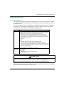
NOTICE
Read these instructions carefully, and look at the equipment to become familiar with the device
before trying to install, operate, or maintain it. The following special messages may appear
throughout this documentation or on the equipment to warn of potential hazards or to call attention
to information that clarifies or simplifies a procedure.
EIO0000001584 09/2014
5
PLEASE NOTE
Electrical equipment should be installed, operated, serviced, and maintained only by qualified
personnel. No responsibility is assumed by Schneider Electric for any consequences arising out of
the use of this material.
A qualified person is one who has skills and knowledge related to the construction and operation
of electrical equipment and its installation, and has received safety training to recognize and avoid
the hazards involved.
BEFORE YOU BEGIN
Do not use this product on machinery lacking effective point-of-operation guarding. Lack of
effective point-of-operation guarding on a machine can result in serious injury to the operator of
that machine.
WARNING
UNGUARDED EQUIPMENT
Do not use this software and related automation equipment on equipment which does not have
point-of-operation protection.
Do not reach into machinery during operation.
Failure to follow these instructions can result in death, serious injury, or equipment
damage.
This automation equipment and related software is used to control a variety of industrial processes.
The type or model of automation equipment suitable for each application will vary depending on
factors such as the control function required, degree of protection required, production methods,
unusual conditions, government regulations, etc. In some applications, more than one processor
may be required, as when backup redundancy is needed.
Only you, the user, machine builder or system integrator can be aware of all the conditions and
factors present during setup, operation, and maintenance of the machine and, therefore, can
determine the automation equipment and the related safeties and interlocks which can be properly
used. When selecting automation and control equipment and related software for a particular
application, you should refer to the applicable local and national standards and regulations. The
National Safety Council’s Accident Prevention Manual (nationally recognized in the United States
of America) also provides much useful information.
In some applications, such as packaging machinery, additional operator protection such as pointof-operation guarding must be provided. This is necessary if the operator’s hands and other parts
of the body are free to enter the pinch points or other hazardous areas and serious injury can occur.
Software products alone cannot protect an operator from injury. For this reason the software
cannot be substituted for or take the place of point-of-operation protection.
6
EIO0000001584 09/2014
Ensure that appropriate safeties and mechanical/electrical interlocks related to point-of-operation
protection have been installed and are operational before placing the equipment into service. All
interlocks and safeties related to point-of-operation protection must be coordinated with the related
automation equipment and software programming.
NOTE: Coordination of safeties and mechanical/electrical interlocks for point-of-operation
protection is outside the scope of the Function Block Library, System User Guide, or other
implementation referenced in this documentation.
START-UP AND TEST
Before using electrical control and automation equipment for regular operation after installation,
the system should be given a start-up test by qualified personnel to verify correct operation of the
equipment. It is important that arrangements for such a check be made and that enough time is
allowed to perform complete and satisfactory testing.
CAUTION
EQUIPMENT OPERATION HAZARD
Verify that all installation and set up procedures have been completed.
Before operational tests are performed, remove all blocks or other temporary holding means
used for shipment from all component devices.
Remove tools, meters, and debris from equipment.
Failure to follow these instructions can result in injury or equipment damage.
Follow all start-up tests recommended in the equipment documentation. Store all equipment
documentation for future references.
Software testing must be done in both simulated and real environments.
Verify that the completed system is free from all short circuits and temporary grounds that are not
installed according to local regulations (according to the National Electrical Code in the U.S.A, for
instance). If high-potential voltage testing is necessary, follow recommendations in equipment
documentation to prevent accidental equipment damage.
Before energizing equipment:
Remove tools, meters, and debris from equipment.
Close the equipment enclosure door.
Remove all temporary grounds from incoming power lines.
Perform all start-up tests recommended by the manufacturer.
EIO0000001584 09/2014
7
OPERATION AND ADJUSTMENTS
The following precautions are from the NEMA Standards Publication ICS 7.1-1995 (English
version prevails):
Regardless of the care exercised in the design and manufacture of equipment or in the selection
and ratings of components, there are hazards that can be encountered if such equipment is
improperly operated.
It is sometimes possible to misadjust the equipment and thus produce unsatisfactory or unsafe
operation. Always use the manufacturer’s instructions as a guide for functional adjustments.
Personnel who have access to these adjustments should be familiar with the equipment
manufacturer’s instructions and the machinery used with the electrical equipment.
Only those operational adjustments actually required by the operator should be accessible to
the operator. Access to other controls should be restricted to prevent unauthorized changes in
operating characteristics.
8
EIO0000001584 09/2014
About the Book
At a Glance
Document Scope
This document describes the adapter modules that can be used in X80 RIO drops.
This guide describes 3 adapter modules:
BME CRA 312 10
BMX CRA 312 10
BMX CRA 312 00
NOTE: The specific configuration settings contained in this guide are for instructional purposes
only. The settings required for your specific application can be different from the examples
presented in this guide.
NOTE: The architectures described in this document have been tested and validated in various
scenarios. If you intend to use architectures different than the ones described in this document,
test and validate them thoroughly before implementing.
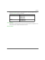
Validity Note
This document is valid for X80 remote I/O systems when used with Unity Pro 8.1 or later.
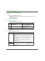
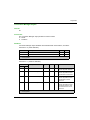
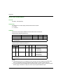
The technical characteristics of the devices described in this document also appear online. To
access this information online:
Step
Action
1
Go to the Schneider Electric home page www.schneider-electric.com.
2
In the Search box type the reference of a product or the name of a product range.
Do not include blank spaces in the model number/product range.
To get information on grouping similar modules, use asterisks (*).
3
If you entered a reference, go to the Product Datasheets search results and click on the
reference that interests you.
If you entered the name of a product range, go to the Product Ranges search results and click
on the product range that interests you.
4
If more than one reference appears in the Products search results, click on the reference that
interests you.
5
Depending on the size of your screen, you may need to scroll down to see the data sheet.
6
To save or print a data sheet as a .pdf file, click Download XXX product datasheet.
EIO0000001584 09/2014
9
The characteristics that are presented in this manual should be the same as those characteristics
that appear online. In line with our policy of constant improvement, we may revise content over time
to improve clarity and accuracy. If you see a difference between the manual and online information,
use the online information as your reference.
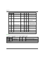
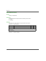
Related Documents
10
Title of Documentation
Reference Number
Modicon M580 System Planning Guide
HRB62666 (English),
HRB65318 (French),
HRB65319 (German),
HRB65320 (Italian), HRB65321
(Spanish) HRB65322 (Chinese)
Modicon M580 Hardware Reference Manual
HRB62666 (English),
HRB65318 (French),
HRB65319 (German),
HRB65320 (Italian), HRB65321
(Spanish) HRB65322 (Chinese)
Modicon M580 BME NOC 03•1 Ethernet Communication Module
Installation and Configuration Guide
HRB62665 (English),
HRB65311 (French),
HRB65313 (German),
HRB65314 (Italian),
HRB65315 (Spanish),
HRB65316 (Chinese)
Modicon M580 Change Configuration on the Fly User Guide
EIO0000001590 (English),
EIO0000001591 (French),
EIO0000001592 (German),
EIO0000001594 (Italian),
EIO0000001593 (Spanish),
EIO0000001590 (Chinese)
Modicon M340/X80 BMX NRP 020• Fiber Optic Repeater Module
User Guide
EIO0000001108 (English),
EIO0000001109 (French),
EIO0000001110 (German),
EIO0000001111 Spanish),
EIO0000001112 (Italian),
EIO0000001113 (Chinese)
Modicon M340/X80 with Unity Pro Analog Input/Output Modules
User Manual
35011978 (English),
35011979 (German),
35011980 (French),
35011981 (Spanish),
35011982 (Italian),
35011983 (Chinese)
EIO0000001584 09/2014
Title of Documentation
Reference Number
Modicon M340/X80 with Unity Pro Discrete Input/Output Modules
User Manual
35012474 (English),
35012475 (German),
35012476 (French),
35012477 (Spanish),
35012478 (Italian),
35012479 (Chinese)
Modicon M340/X80 with Unity Pro BMX EHC 0200 Counting Module 35013355 (English),
User Guide
35013356 (German),
35013357 (French),
35013358 (Spanish),
35013359 (Italian),
35013360 (Chinese)
BMX ERT 1604 T Modicon M340 ERT Module User Manual
EIO0000001121 (English),
EIO0000001122 (French),
EIO0000001123 (German),
EIO0000001124 (Spanish),
EIO0000001125 (Italian),
EIO0000001126 (Chinese)
System Time Stamping User Guide
EIO0000001217 (English),
EIO0000001707 (French),
EIO0000001708 (German),
EIO0000001709 (Spanish),
EIO0000001710 (Italian),
EIO0000001711 (Chinese)
Applicative Time Stamping with Unity Pro User Guide
EIO0000001268 (English),
EIO0000001702 (French),
EIO0000001703 (German),
EIO0000001704 (Spanish),
EIO0000001705 (Italian),
EIO0000001706 (Chinese)
Unity Pro Program Languages and Structure Reference Manual
35006144 (English),
35006145 (French),
35006146 (German),
35006147 (Spanish),
35013361 (Italian),
35013362 (Chinese)
Unity Pro Operating Modes
33003101 (English),
33003102 (French),
33003103 (German),
33003104 (Spanish),
33003696 (Italian),
33003697 (Chinese)
EIO0000001584 09/2014
11
Title of Documentation
Reference Number
Unity Pro Installation Manual
35014792 (French),
35014793 (English),
35014794 (German),
35014795 (Spanish),
35014796 (Italian),
35012191 (Chinese)
Unity Pro Installation Manual Modicon X80 with Unity Pro HART
Analog Input/Output Modules User Guide
EAV16400 (English),
EAV28404 (French),
EAV28384 (German),
EAV28360 (Spanish),
EAV28413 (Italian),
EAV28417 (Chinese)
You can download these technical publications and other technical information from our website
at www.schneider-electric.com.
12
EIO0000001584 09/2014
Modicon M580
Characteristics of Ethernet Remote I/O Modules
EIO0000001584 09/2014
Chapter 1
Characteristics of Ethernet Remote I/O Modules
Characteristics of Ethernet Remote I/O Modules
Introduction
This chapter describes the adapter modules that can be used in the remote drops of an X80
system. Specifically, these modules are:
BME CRA 312 10
BMX CRA 312 10
BMX CRA 312 00
This chapter includes physical characteristics, port descriptions, and agency specifications for
these modules.
What Is in This Chapter?
This chapter contains the following topics:
Topic
Page
Adapter Module Descriptions
14
LED Indicators on Adapter Modules
17
Adapter Ethernet Ports
19
Remote I/O Network Cable Installation
21
Modicon X80 I/O Modules
22
Hardened (H) Equipment
27
Standards, Certifications and Operational Recommendations
28
EIO0000001584 09/2014
13
Characteristics of Ethernet Remote I/O Modules
Adapter Module Descriptions
Introduction
A remote I/O drop consists of 1 or 2 racks of Modicon X80 I/O modules and/or third-party PME
SWT 0100 modules. A remote I/O drop is connected to the daisy-chain loop on which the Ethernet
remote I/O network resides. Each remote drop contains one BM• CRA 312 •0 adapter module.
Each rack in a remote drop contains its own power supply module.
Remote adapter modules are available as Ethernet BME and X Bus BMX communicators. To use
X80 I/O modules that require Ethernet, choose a BME-style adapter module. If your X80 I/O uses
only X Bus for backplane communication, then you can use a BMX-style adapter module.
The adapter modules are:
14
Adapter
Description
X80 standard EIO
adapter
The BMX CRA 312 00 is a basic adapter module that supports X Bus
communications across the remote backplane, but not Ethernet.
It does not support:
more than 9 I/O modules
an extension rack
special-purpose or Ethernet I/O modules
native timestamping
service port
I/O to be solved more than once per logic scan in the remote drop.
(It only handles MAST (see page 69) tasks. Your application
cannot assign FAST and AUX tasks in it.
X80 performance
EIO adapter
The BMX CRA 312 10 adapter module supports X Bus
communications across the remote backplane, but not Ethernet.
It supports:
up to 17 I/O modules
an extension rack
special-purpose modules
native timestamping
service port
MAST (see page 69), FAST (see page 69), and AUX0
(see page 69)/AUX1 (see page 70) task customization of the I/O
scanner service
eX80 performance
EIO adapter
The BME CRA 312 10 adapter supports Ethernet and X Bus
communications across the remote backplane. This adapter needs to
be installed in an Ethernet backplane.
It supports:
the capabilities of a BMX CRA 312 10 adapter
Ethernet I/O modules on rack slots connected to the Ethernet
backplane in the remote drop, such as the BME AHI Hartcompatible analog module, BME AHO 0412 and, PME SWT 0100
modules
EIO0000001584 09/2014
Characteristics of Ethernet Remote I/O Modules
Functionality
The adapters exchange data via an I/O scanner service, which resides in the CPU on the main
local rack of your PAC system:
The input data from the remote I/O drop is collected and published to the I/O scanner.
The output modules are updated with the data received from the I/O scanner.
The protocol used for exchange is EtherNet/IP.
The exchanges are deterministic, which means that the remote I/O logic is scanned regularly in
a scheduled and predictable manner.
NOTE: Refer to your system hardware reference manual to select a CPU that supports the I/O
scanner capability.
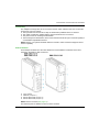
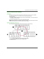
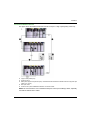
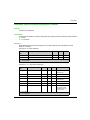
External Features
These adapter modules have the same dimensions and installation constraints as the other
modules in the Modicon X80 product line:
1
2
3
4
5
LED display
rotary switches
SERVICE port (ETH 1)
DEVICE NETWORK port (ETH 2)
DEVICE NETWORK port (ETH 3)
NOTE: Refer to the LEDs (see page 17).
The Ethernet ports are labeled on the front of the modules.
EIO0000001584 09/2014
15
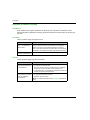
Characteristics of Ethernet Remote I/O Modules
NOTE: Insert dust covers into the unused Ethernet ports on the adapter modules:
16
EIO0000001584 09/2014
Characteristics of Ethernet Remote I/O Modules
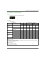
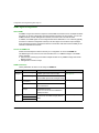
LED Indicators on Adapter Modules
Display
The LEDs are on the front of the adapter module:
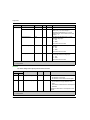
Indications
LED conditions:
Module State(1)
Description
Run
Green
Red
Green
Red
Green
Red
power-up
sequence
Order of LEDs blinking
1
2
3
4
5
6
not configured
IP address not valid
-
-
flashing
off
off
off
valid IP address, but invalid
configuration
off
off
flashing
off
flashing
off
no external error detected
flashing
off
-
-
flashing
off
external error detected
flashing
on
-
-
flashing
off
I/O data
communication
established
STOP
flashing
(NOTE 1) on
off
on
off
RUN
on
(NOTE 2) on
off
on
off
detected error
states
recoverable error
-
-
off
flashing
-
-
nonrecoverable error
flashing
on
off
on
-
-
duplicate IP address
-
-
-
-
off
on
flashing
off
off
on
off
on
configured
during OS firmware update
IO
MS (Module Status) NS (Network
Status)
(1) For more information about the module states, refer to your system hardware reference manual.
NOTE 1 (STOP state):
on: An input or output is a detected error that originates in a module, or a channel configuration or a channel
configuration error has been detected.
off: Operations are normal.
NOTE 2 (RUN state):
on: External error is detected.
off: External error is not detected.
EIO0000001584 09/2014
17
Characteristics of Ethernet Remote I/O Modules
Ethernet Port Indications
These LEDs report the status of the Ethernet port:
Name
LINK
ACT
18
Color
Status
Description
green
on
100 Mbps link detected
yellow
on
10 Mbps link detected
-
off
no detected link
green
blinking
active Ethernet link (transmit or receive)
-
off
inactive Ethernet link
EIO0000001584 09/2014
Characteristics of Ethernet Remote I/O Modules
Adapter Ethernet Ports
Ethernet Port Descriptions
2 of the Ethernet ports allow implicit I/O exchanges with the I/O scanner in the CPU. (An implicit
I/O exchange has a maximum frame size of 1400 bytes.) The ports can be implemented alone or
in redundant mode.
You can use a maximum of 8 or 16 adapters in a single Ethernet remote I/O network depending
on the CPU used. For network topology planning, refer to the planning guide for your system.
These adapter modules have 2 or 3 10/100 Base-T Ethernet ports:
Port
Description
SERVICE
The SERVICE port allows the diagnosis of Ethernet device network ports and
provides access to external tools and devices (Unity Pro, ConneXium Network
Manager, HMI, and so forth). The port supports these modes:
access port (default): This mode supports Ethernet communications.
port mirroring: In this mode, data traffic from one of the other 2 ports is
copied to this port. This allows a connected management tool to monitor
and analyze the port traffic.
disabled
NOTE:
The BMX CRA 312 00 does not have a SERVICE port.
You can configure the SERVICE port either ONLINE or OFFLINE.
In port mirroring mode, the SERVICE port acts like a read-only port. That
is, you cannot access devices (ping, connection to Unity Pro, and so forth)
through the SERVICE port.
Refer to Service Port Configuration (see page 52).
DEVICE
NETWORK
The DEVICE NETWORK copper ports are used to put the drop on the simple
daisy chain loop.
They provide:
connections for remote I/O communications
cable redundancy
CAUTION
ETHERNET CONNECTION NON-OPERATIONAL
Do not connect a device with a speed in excess of 100 Mbit/s to any adapter port.
Failure to follow these instructions can result in injury or equipment damage.
Connecting a device with a speed in excess of 100 Mbit/s , the Ethernet link may not be established
between the device and the module through its port.
EIO0000001584 09/2014
19
Characteristics of Ethernet Remote I/O Modules
BME CRA 312 10 Keying Pin
The BME CRA 312 10 adapter is designed to be installed on an Ethernet backplane in the main
remote rack. The adapter supports the Modicon X80 I/O and partner modules with both Ethernet
and X Bus connections. The 2 bus connectors are shown in items 1 and 2 below.
The adapter also has a keying pin (item 3 below) to keep it from being installed on a BME XBP
PV 01 backplane.
Rear view of the adapter module:
1 X Bus backplane connector
2 Ethernet backplane connector
3 Keying pin
20
EIO0000001584 09/2014
Characteristics of Ethernet Remote I/O Modules
Remote I/O Network Cable Installation
Introduction
Use a daisy chain loop network configuration that implements the RSTP service to establish
redundant communications with at least one of the 2 physical paths between:
the I/O scanner
the adapter modules at each remote drop, dual ring switches (DRSs), or any product that has
the capacity to be RIO scanned
For network topology planning, refer to your system planning guide.
NOTE: Fiber optic ports are not available on the adapter modules. For fiber optic support use either
a BMX NRP 0200 optic fiber conversion module or a pair of DRSs.
Remote I/O Simple Daisy Chain Loop
The CPU supports communications with remote I/O drops in a daisy chain loop:
1
2
3
main local rack with a BME P58 ••40 CPU with the I/O scanner service
X80 remote I/O drops with a BM• CRA 312 •0 adapter module
the daisy chain loop
EIO0000001584 09/2014
21
Characteristics of Ethernet Remote I/O Modules
Modicon X80 I/O Modules
Introduction
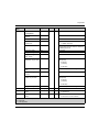
The following I/O modules can be mounted in local racks or RIO drops in an M580 system.
Some of these modules also contain embedded web pages that can be used for configuration and
diagnostics. Web page descriptions are provided in the appropriate product documentation and in
Unity Pro help.
NOTE: Conformally coated (hardened H) versions of many of these modules are also available.
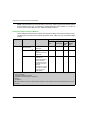
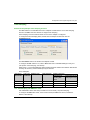
Modicon X80 Analog and Discrete Modules
Modules that require Ethernet across the backplane can be installed only in main local or remote
local racks. They cannot be installed in extended racks.
These I/O modules are supported in Modicon X80 local racks containing a CPU and RIO drops:
Type of
Module
Module
Comments
Installation on...
Main Local Extended
Rack
Local Rack
Main
Remote
Rack
Extended
Remote Rack
—
X
—
—
X
—
Analog I/O Modules
input
BME AHI 0812(1)
output
BME AHO
input
BMX AMI 0410
input
BMX AMI 0800
input
BMX AMI 0810
input/output
BMX AMM 0600
0412(1)
X
These require an
Ethernet
X
backplane and a
BME CRA 312 10
eX80 performance
EIO adapter
module if they are
inserted in a
remote drop.
X
No backplane or
EIO adapter
X
module restrictions
X
X
X
X
X
X
X
X
X
X
X
X
X
X
1 These modules require an Ethernet backplane.
2 In the CPU configuration screen in Unity Pro, you can configure a digital I/O module channel as a RUN/STOP input
by selecting this check box. This can be performed on a local I/O channel in topological I/O data type only.
3 Before installation of I/O modules that use a 125 Vdc power supply, refer to the temperature derating information
in I/O module hardware guides for your platform.
X allowed
— not allowed
22
EIO0000001584 09/2014
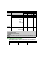
Characteristics of Ethernet Remote I/O Modules
Type of
Module
Module
output
output
Comments
Installation on...
Main Local Extended
Rack
Local Rack
Main
Remote
Rack
Extended
Remote Rack
BMX AMO 0210
X
X
X
X
BMX AMO 0410
X
X
X
X
X
X
X
X
X
X
X
X
X
X
X
X
output
BMX AMO 0802
input
BMX ART 0414
input
BMX ART 0814
The FAST task is
not supported.
(2)
Discrete I/O Modules
input
BMX DAI 0805
X
X
X
X
input
BMX DAI 1602
X
X
X
X
input
BMX DAI 1603
X
X
X
X
input
BMX DAI 1604
X
X
X
X
output
BMX DAO 1605
X
X
X
X
input
BMX DDI 1602
X
X
X
X
input
BMX DDI 1603
X
X
X
X
input
BMX DDI 1604(3)
X
X
X
X
input
BMX DDI 3202 K
X
X
X
X
input
BMX DDI 6402 K
X
X
X
X
input/ output BMX DDM 16022
X
X
X
X
input/ output BMX DDM 16025
X
X
X
X
input/ output BMX DDM 3202 K
X
X
X
X
output
BMX DDO 1602
X
X
X
X
output
BMX DDO 1612
X
X
X
X
output
BMX DDO 3202 K
X
X
X
X
output
BMX DDO 6402 K
X
X
X
X
output
(3)
BMX DRA 0804
X
X
X
X
output
BMX DRA 0805(3)
—
—
X
X
output
BMX DRA 1605
—
—
X
X
1 These modules require an Ethernet backplane.
2 In the CPU configuration screen in Unity Pro, you can configure a digital I/O module channel as a RUN/STOP input
by selecting this check box. This can be performed on a local I/O channel in topological I/O data type only.
3 Before installation of I/O modules that use a 125 Vdc power supply, refer to the temperature derating information
in I/O module hardware guides for your platform.
X allowed
— not allowed
EIO0000001584 09/2014
23
Characteristics of Ethernet Remote I/O Modules
NOTE: Schneider Electric recommends that you use Unity Loader to upgrade the modules with the
latest available version. (It is not necessary to update a BMX ART 0414 module, V2.1 or later, as
it works correctly with a BM• CRA 312 •0X80 EIO adapter module.)
Intelligent and Special Purpose Modules
These intelligent/special purpose modules are supported in M580 local racks (containing a CPU
with Ethernet I/O scanner service) and RIO drops that contain a BM• CRA 312 •0 X80 EIO adapter
module:
Type
Module
Comment
Installation on...
Main Local Extended
Rack
Local Rack
Main
Extended
Remote Remote
Rack
Rack
X
X
X
X
BMX NOR 0200(1)(2)
Not supported in RIO X
drops.
The FAST task is not
supported.
X
—
—
BMX EIA 0100
A maximum of 4 AS-i X
modules per
main/extended local
racks is allowed.
A maximum of 2 AS-i
modules per drop is
allowed.
A maximum of 16 ASI modules is allowed
in the drops in an
M580 system.
X
X
X
communication BMX NOM 0200(1)(2)(3) The FAST task is not
supported.
1 If a BMX NOM 0200 module and a BMX EIA 0100 module are included on the same RIO drop, only one of each
module is allowed.
2 Only MAST tasks are supported.
3 The Modbus character mode is supported.
X allowed
— not allowed
NOTE: The maximum number of communication modules you can install on the local rack depends upon the CPU
you choose.
24
EIO0000001584 09/2014
Characteristics of Ethernet Remote I/O Modules
Type
Module
counting
Comment
Installation on...
Main Local Extended
Rack
Local Rack
Main
Extended
Remote Remote
Rack
Rack
BMX EHC 0200
X
X
X
X
BMX EHC 0800
X
X
X
X
BMX EAE 0300
X
In RIO drops:
Events are not
supported.
If events are
needed, move the
module to the
local rack.
A maximum of 36
channels can be
configured.
X
X
X
time stamping
BMX ERT 1604T
X
X
X
X
fiber cable
conversion
BMX NRP 0200
X
X
X
X
motion
BMX MSP 0200
It is not supported in
RIO drops
X
X
—
—
weighing
PME SWT 0100(5)
This is an Ethernet
weighing transmitter
(1 channel).
X
—
X
—
1 If a BMX NOM 0200 module and a BMX EIA 0100 module are included on the same RIO drop, only one of each
module is allowed.
2 Only MAST tasks are supported.
3 The Modbus character mode is supported.
X allowed
— not allowed
NOTE: The maximum number of communication modules you can install on the local rack depends upon the CPU
you choose.
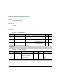
Modicon X80 Analog and Discrete Module Versions
When the following modules are used in a local rack (containing a CPU) and RIO drops, they
require these versions:
Module
Product Version
Software Version
BMX AMI 0410
PV5
SV1.1
BMX AMM 0600
PV5 or later
SV1.2
BMX AMO 0210
PV7 or later
SV1.1
EIO0000001584 09/2014
25
Characteristics of Ethernet Remote I/O Modules
Module
BMX ART 0414
BMX ART 0814
Product Version
Software Version
PV5, PV6
SV2.0
PV7
SV2.1
PV3, PV4
SV2.0
PV5 or later
SV2.1
BMX EHC 0200
PV3
SV1.1
BMX EHC 0800
PV3
SV1.1
Hardened Modules
These hardened modules are supported in M580 local racks (containing a CPU) and RIO drops
that contain a BM• CRA 312 •0 EIO adapter module. For details regarding hardened modules,
refer to the manuals for each of these modules.
Type of Module
Module
counting
BMX ECH 0200 H
synchronous serial interface (SSI)
BMX EAE 0300 H
analog input
BMX ART 0414 H
BMX ART 0814 H
BMX AMI 0810 H
analog output
BMX AMP 0210 H
BMX AMO 0410 H
BMX AMO 0810 H
discrete input
BMX DDI 1602 H
BMX DDI 1603 H
discrete output
BMX DAO 1602 H
BMX DDO 1605 H
BMX DDO 1612 H
BMX DRA 0805 H
BMX DRA 1605 H
discrete input/output
BMX DAI 1602 H
BMX DAI 1603 H
BMX DAI 1604 H
BMX DDM 16022 H
BMX DDM 16025 H
TELEFAST wiring accessories
ABE7 CPA 0410 H
ABE7 CPA 0412 H
26
EIO0000001584 09/2014
Characteristics of Ethernet Remote I/O Modules
Hardened (H) Equipment
M580H
The hardened (H) equipment is a ruggedized version of the equipment in your system. It can be
used at extended temperatures (-25...70ºC) (-13...158ºF) and in harsh chemical environments.
This equipment is ATEX certified.
This treatment increases the isolation capability of the circuit boards and their resistance to:
condensation
dusty atmospheres (conducting foreign particles)
chemical corrosion, in particular during use in sulphurous atmospheres (oil, refinery, purification
plant and so on) or atmospheres containing halogens (chlorine and so on)
The hardened equipment, when within the standard temperature range (0...60ºC) (32...140ºF), has
the same performance characteristics as the standard equipment.
If this equipment is operated outside the -25...70ºC (-13...158ºF) temperature range, the
equipment can operate abnormally.
WARNING
UNINTENDED EQUIPMENT OPERATION
Do not operate hardened equipment outside of its specified temperature range.
Failure to follow these instructions can result in death, serious injury, or equipment
damage.
Hardened equipment has a conformal coating applied to its electronic boards. This protection,
when associated with appropriate installation and maintenance, allows it to be more robust when
operating in harsh chemical environments.
EIO0000001584 09/2014
27
Characteristics of Ethernet Remote I/O Modules
Standards, Certifications and Operational Recommendations
Standards and Certifications
For this information, refer to Standards and Certifications (see Modicon M580, Hardware,
Reference Manual).
Operational and Environmental Recommendations
For this information, refer to Operational and Environmental Recommendations
(see Modicon M580, Hardware, Reference Manual).
28
EIO0000001584 09/2014
Modicon M580
Installation
EIO0000001584 09/2014
Chapter 2
Installation
Installation
Overview
This chapter describes the hardware installation of an Modicon X80 remote I/O drop.
What Is in This Chapter?
This chapter contains the following sections:
Section
Topic
Page
2.1
Installing Modicon X80 Modules
30
2.2
Remote I/O Infrastructure Cables
39
EIO0000001584 09/2014
29
Installation
Section 2.1
Installing Modicon X80 Modules
Installing Modicon X80 Modules
At a Glance
This section describes the installation of an Modicon X80 I/O adapter module.
What Is in This Section?
This section contains the following topics:
Topic
30
Page
Maximum Configuration in Remote I/O Drops
31
Modicon X80 Backplane Considerations
32
Adapter and I/O Module Installation
34
Setting the Location of the Ethernet Remote I/O Drop
38
EIO0000001584 09/2014
Installation
Maximum Configuration in Remote I/O Drops
Maximum Configuration
The maximum number of I/O modules in an Modicon X80 remote I/O drop (with both a main remote
rack and an extension remote rack) using a BM• CRA 312 •0 adapter depends on the CPU used
in the main local rack.
Refer to your system hardware reference manual toensure that you select a CPU that supports the
number and types of I/O modules you need.
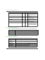
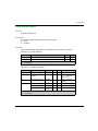
This table shows the maximum number of modules in a remote I/O drop with a remote extension
rack:
Module Type
Number of Modules in a Drop
remote I/O adapter
1
power supply
2
bus extension
I/O(2)
(1)
2
Depends on the CPU and platform used
(1) A bus extender attaches to the end of each rack and does not use a rack slot.
(2) Refer to the list of modules that remote I/O installations support (see page 22).
EIO0000001584 09/2014
31
Installation
Modicon X80 Backplane Considerations
Introduction
An X80 remote I/O drop can have 1 or 2 racks:
1. main remote I/O rack: BME XBP • •00 or BMX XBP • •0
This rack is required in a drop and contains a BMX CRA 312 00, BME CRA 312 10, or
BMX CRA 312 10 adapter, a power supply, and, optionally, I/O modules.
2. extended remote I/O rack: only BMX XBP • •0
This rack is optional in a drop and contains only I/O modules.
Extended remote racks must be PV 02 or higher backplane. This means that any modules that
require Ethernet across the backplane must go in the main remote rack.
NOTE: The BMX CRA 312 00 does not support an extended remote I/O rack.
NOTE: The mounting screws on the left side of the backplane may be accessible without
unplugging the power supply module. Mount the backplane using the far left fastening hole on the
panel.
Compatible Racks
The following racks can be used in an Modicon X80 remote I/O drop:
X BUS (PV 02 or later) backplanes:
BMX XBP 0400
BMX XBP 0600
BMX XBP 0800
BMX XBP 1200
BMX XBP 0400 H
BMX XBP 0600 H
BMX XBP 0800 H
BMX XBP 1200 H
Ethernet backplanes:
BME XBP 0400
BME XBP 0800
(1)
BME XBP 1200
BME XBP 0400 H
BME XBP 0800 H
(1)
BME XBP 1200 H
(1) The 12-slot Ethernet rack has 8 Ethernet-X Bus slots and 4 X Bus-only slots.
Rack Selection Considerations
A BME CRA 312 10 adapter:
must be installed in an Ethernet rack.
installed in a PV 02 or higher backplane, it is not damaged but it does not start.
cannot be installed in a PV 01 backplane because of its keying pin (see page 20).
32
EIO0000001584 09/2014
Installation
For a BMX CRA 312 10 or a BMX CRA 312 00 adapter:
install it in a PV 02 or higher backplane.
if installed in an Ethernet backplane, it cannot handle any Ethernet modules. However, it can
handle modules that is handles in a PV 02 or higher backplane.
Racks and Extensions
An Modicon X80 remote I/O drop can include 2 racks. In a 2-rack drop, the racks are linked with 2
bus extender modules and a cable:
Bus Extender Module
Cable
BMX XBE 1000
BMX XBC •••K (0.8 to 12 m)
Grounding Considerations
DANGER
ELECTRICAL SHOCK HAZARD
Switch off the power supply to the PAC at both ends of the connection before inserting or
removing an Ethernet cable.
Use suitable insulation equipment when inserting or removing all or part of this equipment.
Failure to follow these instructions will result in death or serious injury.
Do not apply power to an Modicon X80 rack until connections are made at both ends of the
Ethernet cable. For example, connect the cable to both the BME CRA 312 10 and another device
(adapter module) or DRS before you turn on the power.
Refer to your system hardware reference manual for details about the DRSs.
Use fiber-optic cable to establish a communications link when it is not possible to master the
potential between the 2 grounds.
EIO0000001584 09/2014
33
Installation
Adapter and I/O Module Installation
Introduction
Observe the following guidelines when you install these adapter modules in an Modicon X80
remote I/O drop):
BME CRA 312 10
BMX CRA 312 10
BMX CRA 312 00
Order of Module Installation
Install modules in the selected rack in Unity Pro in this order:
1. install the adapter module
2. install a power supply
3. install I/O modules
Grounding Considerations
DANGER
ELECTRICAL SHOCK HAZARD
Switch off the power supply to the PAC at both ends of the connection before inserting or
removing an Ethernet cable.
Use suitable insulation equipment when inserting or removing all or part of this equipment.
Failure to follow these instructions will result in death or serious injury.
Use fiber optic cable to establish a communications link when it is not possible to equalize the
potentials between 2 grounds.
NOTE: Refer to the ground connection information in the Grounding and Electromagnetic
Compatibility of PLC Systems User Manual.
Installation of the Adapter
Unity Pro automatically installs a BM• CRA 312 •0 adapter module in slot 0 in a remote I/O drop.
Select a Power Supply
Power consumption is 1.2 A on a 5 Vdc power rail on the backplane (6 W). The adapter module
supports modules on 1 or 2 racks. (Power consumption has no relation to the number of installed
rack modules.)
In Modicon X80 Ethernet remote I/O drops, insert the power supply only in the double-wide slot to
the left of slot 0 marked CPS.
34
EIO0000001584 09/2014
Installation
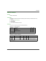
Select a power supply that suits your system requirements. These power supplies, and their
hardened (see page 27) versions, are supported:
Power Supply Type
Modicon X80 Module
standalone
redundant
ABL 8RED 24400
ABL 8REM 24030
ABL 8RPS 24030
BMX CPS 2010
BMX CPS 3020
BMX CPS 2000
BMX CPS 3500
BMX CPS 3540
Select I/O Modules
Use the Unity Pro Hardware Catalog to select the I/O modules needed in your application in the
main remote rack and, if available, the extended remote rack.
Mounting a Module
EIO0000001584 09/2014
35
Installation
Use this procedure to install adapters and I/O modules in a rack:
Step
Action
1
Hold the module at an angle and mount it on the 2 hooks near the bottom of the
backplane. The figure shows the correct way to hold the module:
2
Swing the module up so that the connector engages the backplane connector.
3
Use a phillips-head screw driver to tighten the screw at the top of the module 2...4
in-lbs (0.22 to 0.45 N•m) of torque.
Replacing a Module
You can replace an Modicon X80 module at any time using another module with compatible
firmware. The replacement module obtains its operating parameters over the backplane
connection from the CPU. The transfer occurs immediately at the next cycle to the device.
NOTE: The operating parameters that the CPU sends to a replacement module do not include any
parameter values that were edited in the original module using explicit messaging SET commands.
Installation Results
Applying power to the main local rack after the adapter module is installed can result in either:
Successful installation:
Initialization is finished.
Interconnections to other modules are validated (drop adapter module only).
36
EIO0000001584 09/2014
Installation
Unsuccessful installation:
Initialization does not finish.
Interconnections to other modules are not validated (drop adapter modules only).
You can see the status of the installation on the adapter LED display (see page 17).
EIO0000001584 09/2014
37
Installation
Setting the Location of the Ethernet Remote I/O Drop
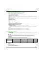
Setting Rotary Switches
Set the location of the remote I/O drop on the network with the rotary switches on the front of the
adapter module:
NOTE: Set the rotary switches before you apply power to the module and before you download the
application.
The values you set are applied during a power cycle. If you change the switch settings after the
module has powered up, the Module Status LED (see page 17) is activated and a mismatch
message is logged in the module diagnostic.
If you want to return to the original setting of a modified rotary switch (and the other switch was
changed), turn the switch until the Module Status LED goes from red to green.
New values on the rotary switches are implemented at the next power cycle. Set the value before
starting the module (valid values: 00 ... 159).
The values on the rotary switches combine with the device prefix (for example, BMECRA_xxx or
BMXCRA_xxx) to create the device name (where xxx represents the value of the rotary switches).
The preceding figure shows the Tens switch set to 00 and the Ones switch set to 1, for a device
name of BMECRA_001.
NOTES:
The rotary switches can be manipulated with a small flat-tipped screwdriver.
No software is required to configure or enable the rotary switches.
Do not use the Stored and Clear IP settings on the Ones rotary switch as they do not apply to
remote I/O installations.
38
EIO0000001584 09/2014
Installation
Section 2.2
Remote I/O Infrastructure Cables
Remote I/O Infrastructure Cables
What Is in This Section?
This section contains the following topics:
Topic
Page
Cable Installation
40
Duplicate IP Address Checking
42
Loss of I/O Connection
43
EIO0000001584 09/2014
39
Installation
Cable Installation
Introduction
A copper cable connection between 2 consecutive remote I/O drops cannot exceed 100 m. A fiber
cable connection between 2 consecutive remote I/O drops cannot exceed 15 km (single mode) or
2.5 km (multi-mode).
For more information, refer to racks installation and assembly (see Modicon M580, Hardware,
Reference Manual) and grounding and cabling (see Grounding and Electromagnetic Compatibility
of PLC Systems, Basic Principles and Measures, User Manual).
40
EIO0000001584 09/2014
Installation
Connections Between Devices
This figure shows the distances between remote I/O drops in a high-capacity daisy chain loop:
1
2
3
4
5
6
main local rack
copper cable (twisted pair)
remote I/O drop
DRSs (with copper and optic fiber ports): This DRS extends the distance between devices using fiber optic
cable (up to 15 km).
fiber optic cable
remote I/O drop with a BMX NRP 0200 fiber converter module
NOTE: We recommend the use of shielded twisted pair CAT5e (10/100 Mbps) cables, especially
ConneXium 490NTC•000•• cables.
EIO0000001584 09/2014
41
Installation
Duplicate IP Address Checking
Introduction
Each adapter has a single IP address for its Ethernet ports. Therefore, the address conflict
detection algorithm (duplicate IP checking) is performed based on the status (link up, link down) of
the ports.
Link Down
These conditions apply when links are lost:
Link Status
Description
A transition has occurred
from 1 connected link to
all links down.
When no module ports are connected to a cable (all links are
down), all services are reset. For example, I/O connections,
Modbus connections, and explicit EtherNet/IP connections
close, but low-level network services (like RSTP or switches) are
not affected. The updated Net Status LED indicates the status.
There is 1 link down and
at least 1 connected link.
There is no impact on services that are running in the module.
Link Up
These conditions apply when links are added:
Link Status
Description
A transition has occurred A duplicate IP check is performed:
from no connected links to no duplicate: All services start.
1 connected link.
duplicate: I/O services stop. The BM• CRA 312 •0 adapter
module gets new configuration and downloads the IP
configuration again. The system goes to default IP and the I/O
modules are set to the fallback mode.
A transition has occurred
from at least 1 connected
link to an additional
connected link.
42
A duplicate IP check is performed:
no duplicate: All services continue.
duplicate: All services stop.
NOTE: The updated Net Status LED (see page 17) indicates the
status.
EIO0000001584 09/2014
Installation
Loss of I/O Connection
Conditions
An I/O connection can be lost to a BME CRA 312 10 or BMX CRA 312 •0 under these conditions:
Performing a hot swap by replacing an adapter module with the same type.
There is no remote I/O cable connection.
The I/O connection is closed while the CPU is reconfigured.
Remote Adapter Fallback
In some instances, the remote I/O adapter module can lose I/O connections for a period longer
than the configured hold up time. During the hold up, the adapter tries to get IP and configuration
parameters from the BME P58 ••40 CPU. If the adapter does not obtain those parameters during
the hold up time, the following happens:
inputs: retain last known values
outputs: set to configured fallback value
NOTE: Configure the hold up time on the Unity Pro Parameter tab (see page 54). For more
information, refer to your system planning guide.
Adapter Hot Swap
From the system point of view, during an adapter hot swap, when the adapter is removed the I/O
values go to fallback values. When the new adapter inserted and switches on and is configured,
the I/O values reset to their values before the hot swap.
To reduce the number of transitions after a hot swap, set the configured fallback state the same as
the default fallback state (module powered-on but not configured) before performing the hot swap.
EIO0000001584 09/2014
43
Installation
44
EIO0000001584 09/2014
Modicon M580
Configuration and Programming with Unity Pro
EIO0000001584 09/2014
Chapter 3
Configuration and Programming with Unity Pro
Configuration and Programming with Unity Pro
Introduction
Use Unity Pro to configure your remote drops for Ethernet communications.
What Is in This Chapter?
This chapter contains the following sections:
Section
Topic
Page
3.1
Creating a Unity Pro Project
46
3.2
Unity Pro Configuration for Remote I/O Ethernet Modules
48
3.3
Unity Pro Configuration for Remote I/O Drops
53
EIO0000001584 09/2014
45
Configuration and Programming with Unity Pro
Section 3.1
Creating a Unity Pro Project
Creating a Unity Pro Project
Configuring the Remote I/O Drop
Rack Considerations
Remote I/O rack considerations:
The number of the first slot in a X80 rack is 0. Therefore, a 4-slot rack includes slot numbers 0,
1, 2, 3.
You can cut or copy other devices in the remote drop and paste them in any rack of the same
type, but you cannot move objects from a local rack to the drop or from a drop to the local rack.
Also, you can only perform these actions (cut, copy, paste) in the same device editor.
Configuring a Remote Main Remote I/O Drops
When a BME P58 ••40 CPU module in the main local rack Unity Pro automatically creates a
second bus, the EIO Bus.
Use these instructions to configure a main remote I/O drop (on a EIO Bus):
46
Step
Action
1
In the Project Browser, double-click EIO
Tools →Project Browser →
Bus to see the (empty) remote I/O local rack. Structural view →Project →
Configuration →EIO Bus
Comment
2
In the EIO Bus window, double-click the
square link connector to access the available
racks.
The New Device dialog appears.
3
Select a rack.
This example uses the 4-slot
BME XBP 0400 rack: New Device →
Part Number →Modicon M580
remote drop →Rack →
BME EEP 0400.
4
In the Drop end communicator area,
select a CRA adapter.
This example uses the default
BME CRA 312 10 adapter.
The rack with the CRA adapter opens.
5
Click OK.
6
Click the rack to the left of the CRA adapter to This example uses a BMX CPS 2000.
add a power supply.
7
Double-click empty slots to add Modicon
For this example, none are added.
M580 remote drop modules to the EIO Bus.
8
Save the file.
Click File →Save.
EIO0000001584 09/2014
Configuration and Programming with Unity Pro
To add:
another remote I/O drop, click the rounded square at the bottom of the dialog
a remote drop extension rack, click the >> on the right side of the remote drop main rack
NOTE: When physically installing a remote drop extension rack, add Bus Extender modules and
cables (see page 33).
Maximum Channel Configuration
The maximum number of channels that can be configured for an X80 Remote I/O drop is either:
1024 digital channels
1024 channels that include 256 analog channels
The number maximum of input channels that can be configured for analog modules is 236. In such
a configuration, no other modules can be configured in the remote I/O drop.
NOTE: If a serial Modbus network is added to a remote I/O drop, take in to account the number of
channels declared when calculating the number maximum of channel supported by the remote I/O
drop.
Unity Pro Configuration Tabs
After you have placed your modules in the remote drop, double-click the remote I/O drop adapter
module to see the available Unity Pro configuration tabs:
Device DDT (see page 59)
RSTP (see page 49)
SNMP (see page 50)
Service port (see page 52)
The service port is not available on a drop with a BMX CRA 312 00 adapter.
Parameters (see page 54)
Time Stamping (see page 57)
EIO0000001584 09/2014
47
Configuration and Programming with Unity Pro
Section 3.2
Unity Pro Configuration for Remote I/O Ethernet Modules
Unity Pro Configuration for Remote I/O Ethernet Modules
Overview
This section describes the module configuration tabs in Unity Pro. Use the parameters on these
tabs to configure services for a BM• CRA 312 •0 adapter module in an Ethernet remote I/O drop.
What Is in This Section?
This section contains the following topics:
Topic
48
Page
RSTP Bridge Configuration
49
SNMP Agent Configuration
50
Service Port Configuration
52
EIO0000001584 09/2014
Configuration and Programming with Unity Pro
RSTP Bridge Configuration
About RSTP
The RSTP service supports the inherent network communications redundancy provided by a daisy
chain loop. The remote I/O communications automatically find an alternate path if a communication
disruption occurs (for example, a cable breaks or a device becomes inoperable). This service does
not require you to manually enable or disable the communication paths.
Changing RSTP parameters can affect subring diagnostics, I/O determinism, and network
recovery times.
Access the RSTP Tab
Double-click the adapter module in the Unity Pro configuration to access the RSTP tab.
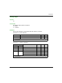
Parameters
This table shows the Bridge priority parameters for the RSTP Operational State on the Unity Pro
RSTP tab:
Bridge Priority
Value
BME P58 ••40
Adapter Module
Root
0
default
-
Backup root
4096
Reserved
-
Participant
32768
-
default
NOTE: Use the default value for the adapter modules.
EIO0000001584 09/2014
49
Configuration and Programming with Unity Pro
SNMP Agent Configuration
About SNMP
An SNMP V1 agent is a software component of the SNMP service that runs on an adapter modules
and gives you access to diagnostic and management information for the modules. You can use
SNMP browsers, network management software, and other tools to access this data.
In addition, the SNMP agent can be configured with the IP addresses of 1 or 2 devices (typically
PCs that run network management software) to be the targets of event-driven trap messages.
Such messages inform the management device of events like cold starts and the inability of the
software to authenticate a device.
Access the SNMP Tab
Double-click the adapter module in the Unity Pro configuration to access the SNMP tab.
The SNMP agent can connect to and communicate with 1 or 2 SNMP managers. The SNMP
service includes:
authentication checking by the Ethernet adapter module of any SNMP manager that sends
SNMP requests
management of events or traps
SNMP Parameters
These parameters are found on the Unity Pro SNMP tab:
Field
Parameter
Description
Value
IP Address IP Address manager 1 The address of the first SNMP manager to which 0.0.0.0 ... 255.255.255.255
managers
the SNMP agent sends notices of traps.
(see page 51)
IP Address manager 2 The address of the second SNMP manager to
which the SNMP agent sends messages of traps.
Agent
Communit
y names
Location
(SysLocation)
device location
Contact (SysContact)
information about the person to contact for
device maintenance
Enable SNMP
manager
unchecked (default): You can edit the Location
and Contact parameters.
checked: You cannot edit the Location and
Contact parameters.
checked/unchecked
Set
password that the SNMP agent requires to read
commands from an SNMP manager (default =
Public)
15 characters (maximum)
Get
Trap
50
31 characters (maximum)
EIO0000001584 09/2014
Configuration and Programming with Unity Pro
Field
Parameter
Description
Security
unchecked (default): not enabled.
Enable
“Authentication failure” checked (enabled): The SNMP agent sends a
trap message to the SNMP manager if an
trap
unauthorized manager sends a Get or Set
command to the agent.
Value
checked/unchecked
Offline IP Address Verification
Offline tests are done to verify that the IP addresses of the managers do not include the following
types of IP addresses:
multicast: 224.0.0.0 or higher
loopback: Any address that starts with 127
broadcast: 255.255.255.255
EIO0000001584 09/2014
51
Configuration and Programming with Unity Pro
Service Port Configuration
Access the Service Port Tab
The BM• CRA 312 10 adapter modules have a service port that can be configured for Ethernet
communications or for port mirroring.
Double-click the adapter module in the Unity Pro configuration to access the Service Port tab.
Service Port Parameters
These parameters are on the Unity Pro Service Port tab:
Field
Parameter
Value
Comment
Service Port
Enabled
—
Enable port and edit port parameters.
Service Port
Mode
Disabled
—
Disable port parameters.
Access
(default)
—
This mode supports Ethernet communications.
Mirroring
—
In port mirroring mode, data traffic from one or more of the other
ports is copied to this port. A connected tool can monitor and
analyze port traffic.
NOTE: In this mode, the service port acts like a read-only port.
That is, you cannot access devices (ping, connection to Unity
Pro, etc.) through the service port.
NOTE: This mode is not available on the BMX CRA 312 00.
Access Port
Configuration
Service Port
Number
ETH1
Port Mirroring
Configuration
Source Port(s) Ports
You cannot edit the value in the Service Port Number field.
Ethernet traffic through both remote I/O ports
ETH2
Ethernet traffic through the first remote I/O port
ETH3
Ethernet traffic through the second remote I/O port
Online Behavior
The Service Port parameters are stored in the application, however you can reconfigure (change)
the parameters in the connected mode. Values that you reconfigure in the connected mode are
sent to the remote drop adapter module or the CPU module in explicit messages. If the module
does not respond to the explicit messages, a message appears.
NOTE: The changed values are not stored, so a mismatch can exist between the parameters that
are being used and those that are in the stored application.
NOTE: The Service Port configuration can be read and modified online using the Service Port
Control Object (see page 110) CIP object.
52
EIO0000001584 09/2014
Configuration and Programming with Unity Pro
Section 3.3
Unity Pro Configuration for Remote I/O Drops
Unity Pro Configuration for Remote I/O Drops
Introduction
This section discusses the use of Unity Pro to configure the Ethernet remote I/O drop and its
adapter module. It includes descriptions of the parameters on the Configuration, Parameter, and
Device DDT tabs in Unity Pro.
What Is in This Section?
This section contains the following topics:
Topic
Page
Configuring Remote Drop Parameters
54
Time Stamping
57
Device DDT Names for Modicon M580 Remote I/O Adapters
59
EIO0000001584 09/2014
53
Configuration and Programming with Unity Pro
Configuring Remote Drop Parameters
Introduction
In the Unity Pro Parameter dialog, you can:
define or verify address information about the adapter module (name, IP address, and
subnetwork mask)
specify a hold-up time interval
specify I/O refresh rates
Access the Parameter Dialog
To access the Parameter dialog in Unity Pro:
Step
Action
Comment
1
Expand (+) EIO Bus in the Unity Pro
Project Browser.
Project Browser →Configuration →
EIO Bus →Modicon M580 remote drop
→Installed BMX/BME rack
2
Double-click the installed adapter.
The X80 performance EIO adapter
window appears.
3
Select the Parameter tab.
The Parameter dialog appears.
Parameter Descriptions
Address information parameters:
54
Parameter
Comment
Device Name
The name of the adapter module includes a fixed prefix and a number
provided by the rotary switch. Valid names conform to this structure:
BM•CRA_xxx, where xxx equals the 3-digit value selected on the rotary
switch.
When the adapter is placed in the remote drop, the number is set to the
device number. The device number does not change if the device moves
to a new location.
Each adapter needs to be assigned a unique number within the
application. A message like this appears when analysis reveals a
duplicate number:
{EIO Bus (2) BME CRA 312 00}: Device name is not unique
IP Address
You cannot edit the IP address and sub network (mask) fields.
Sub Network
NOTE: The IP address is editable only in the IP Configuration tab of the
CPU module. The value for sub network is deduced from the CPU subnetwork mask.
EIO0000001584 09/2014
Configuration and Programming with Unity Pro
Hold up time parameter:
Parameter
Comment
Hold up time
The hold up time represents the time (ms) that device outputs are
maintained in their current states after a communication disruption and
before taking their fallback values:
default value: 1000 ms
valid value range: 50...65,530 ms
If you assign a holdup time value that is less than the recommended minimum value, an I/O module
may move to its fallback state. When communications are restored, the I/O module restarts and
may not operate as anticipated.
WARNING
UNINTENDED EQUIPMENT OPERATION
Do not configure a holdup time value that is less than the recommended minimum values, which
are:
for a periodic application: 4.4 x PAC scan time
for a cyclic application: configured watchdog value
Failure to follow these instructions can result in death, serious injury, or equipment
damage.
Connection parameter:
Parameter
Comment
Scanner->CRA RPI
Outputs: Outputs are passed from the CPU I/O scanner service to
the adapter. The default values are:
periodic mode: default value = 1.1 * MAST period.
cyclic mode: default value = 1/4 * watchdog timeout period.
You cannot edit this value. The outputs are published synchronously
or immediately at the end of the current MAST task.
NOTE: The default value for the watchdog timer is 250 ms. If the
MAST task does not finish within the watchdog period, the process
times out. If the watchdog is greater than 4 times the MAST period,
the drops could switch to fallback while the CPU is running. For
example, MAST period = 20 ms, logic execution = 90 ms, watchdog
time = 100 ms.
EIO0000001584 09/2014
55
Configuration and Programming with Unity Pro
NOTE:
56
When the Periodic mode is selected for the MAST task, the Period value allows the complete
execution of the logic. (The MAST can overrun when its execution time exceeds this value.)
Valid values: 1...255 ms (increment: 1 ms).
When Cyclic mode is selected for the MAST task, the outputs are sent upon the completion of
the task. The Watch Dog value (10 ... 1500 ms, increment: 10 ms, default = 250 ms) should be
greater than the execution time.
EIO0000001584 09/2014
Configuration and Programming with Unity Pro
Time Stamping
Remote I/O Drop Adapter Time Stamping Function
The BME CRA 312 10 and BMX CRA 312 10 adapter modules have a 10 ms time stamping
function. The BMX CRA 312 00 does not support time stamping.
Time stamping of the I/O modules starts as soon as the adapter is configured.
To configure the time stamping buffer, double-click the adapter module and click the
TimeStamping tab:
The local buffer refers to the buffer in the adapter module.
To configure the BM• CRA 312 10, refer to BMX CRA 1604 T Variables Settings in Unity Pro
(see System Time Stamping, User Guide).
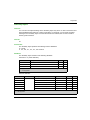
When using 1 or 2 As-i Bus BMX EIA 0200 modules with other modules in a Modicon X80 remote
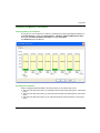
I/O drop, the accuracy of the timestamps may be reduced.
Some examples:
Discrete I/O
32 Channels
Analog I/O
4 Channels
BMX EIA 0100
BMX NOM 0200
Stamping Accuracy
Dedicated High
Accuracy NTP
Server
Internal NTP Server
Stamping Accuracy
6 modules
1 module
0
0
10 ms
10 ms
6 modules
1 module
1 module
1 module
12 ms
22 ms
16 modules
4 modules
1 module
1 module
14 ms
24 ms
1 ms Time Stamping with BMX ERT 1604T
Use a BMX ERT 1604T time stamp module for more accurate (1 ms) time stamping.
To configure the BMX ERT 1604T, refer to this manual (see BMX ERT 1604 T, M340 ERT
Module, User Manual).
EIO0000001584 09/2014
57
Configuration and Programming with Unity Pro
For More Information about Remote Time Stamping
For more information about time stamping in a Modicon X80 remote I/O drop, refer to:
System Time Stamping User Guide
Applicative Time Stamping with Unity Pro User Guide
58
EIO0000001584 09/2014
Configuration and Programming with Unity Pro
Device DDT Names for Modicon M580 Remote I/O Adapters
Introduction
The Device DDT name of the device DDT (see Unity Pro, Program Languages and Structure,
Reference Manual ) is in this format: MOD_COM_#. In Unity Pro, the # symbol represents the order
of the instances of the Device DDT creations. The first created is named MOD_COM_1, the second
created is named MOD_COM_2).
NOTE: These instructions assume that you have already added a drop to your Unity Pro project
(see page 31).
Access the Device DDT Tab
In Unity Pro:
Step
Action
Comment
1
Expand EIO Bus in the Unity Pro
Project Browser to display the
Modicon M580 remote drop
Project Browser →Project →
Configuration →EIO Bus →Modicon
M580 remote drop
2
Double-click the installed drop adapter The X80 performance EIO adapter
in the Modicon X80 Remote drop.
dialog appears.
3
Select the Device DDT tab.
The Implicit device DDT field contains a default name and type.
The I/O structure type for the adapter modules is T_M_CRA_EXT_IN.
EIO0000001584 09/2014
59
Configuration and Programming with Unity Pro
Drop Parameters
In the Unity Pro Device DDT dialog you can configure these parameters for the remote I/O drop:
Parameter
Implicit device DDT
Goto details
Description
Name
The default name of the device DDT includes the module
type, the number of channels, and a suffix that indicates
the insertion number. For example, MOD_TOR_16_128.
Type
module type (cannot be edited)
link to the Device DDT data editor screen
NOTE: Clicking Goto details takes you to Variables tab
in the Data Editor, which displays the drop diagnostic
parameters in T_M_CRA_EXT_IN.
Diagnostic Parameters
This table contains the drop diagnostic parameters in T_M_CRA_EXT_IN for a remote I/O drop
module:
Name
Type
Bit
Description
IO_HEALTH_RACK0
WORD
—
health bits of rack 0: slots 0...15
IO_HEALTH_RACK1
WORD
—
health bits of rack 1: slots 0...15
DEVICE_NAME
string[16]
—
device name of the remote I/O
drop
VERSION
WORD
—
firmware version (Maj, Min) (4
digits coded in BCD)
ROTARY_SWITCHES
BYTE
—
rotary switch value at power up
CRA_STATE
BYTE
—
1: CRA module is idle.
2: CRA module is stopped.
3: CRA module is running.
60
EIO0000001584 09/2014
Configuration and Programming with Unity Pro
Name
Type
Bit
Description
CRA_DIAGNOSTIC GLOBAL_IO_HEALTH
[WORD]
BOOL
0
0: At least one I/O module in the
drop reports bad health.
CCOTF_IN_PROGRESS
BOOL
1
CCOTF is in progress.
CCOTF_INVALID_CONF
BOOL
2
CCOTF is not valid.
IOPL_MISMATCH
BOOL
3
There is an output data mismatch.
SWITCH_CHANGE
BOOL
4
The rotary switch settings have
changed since the last power up.
This bit is reset if the rotary switch
is returned to its original setting.
DROP_COM_HEALTH
BOOL
5
This bit shows the drop
communication health (set to 1
when communication is
established between the RIO drop
and the I/O scanner).
CYCLE_CURR_TIME
UINT
—
This word indicates the execution
time of the last CRA cycle.
It has values between [0.65535]
with a resolution of 0.01 ms,
therefore, the last cycle time is
between [0.655] ms.
CYCLE_MAX_TIME
UINT
—
This word indicates the longest
CRA cycle execution time since
the last start.
It has values between [0.65535]
with a resolution of 0.01 ms,
therefore, the longest cycle time is
between [0,655] ms.
CYCLE_MIN_TIME
UINT
—
This word indicates the shortest
CRA cycle execution time since
the last start.
It has values between [0.65535]
with a resolution of 0.01 ms,
therefore, the shortest cycle time is
between [0.655] ms.
TIME_STAMP_RECORDS
UINT
—
This word contains the number of
records available in the local drop
event buffer.
TS_DIAGNOSTIC_
FLAGS (WORD)
BOOL
0
The time is valid and
synchronized.
EIO0000001584 09/2014
TIME_VALID
61
Configuration and Programming with Unity Pro
Name
CLOCK_FAILURE
CLOCK_NOT_SYNC
Type
Bit
Description
BOOL
1
2
bit 1 = 1 & bit 2 = 1, since
If
power- on CRA adapter has not
received a response from NTP
server.
bit 1 = 0 & bit 2 = 1, CRA
adapter has received a
response from NTP server in
the past but is not currently
receiving the time from the NTP
server
bit 1 = 0 & bit 2 = 0, Time is
valid, CRA adapter is receiving
responses from the NTP
server.
BUFF_FULL
BOOL
3
The local drop event buffer is full.
TS_BUF_FILLED_PCTAGE
BYTE
—
This byte reports the percentage of
the local drop event buffer filled
(0...100).
TS_EVENTS_STATE
BYTE
—
Refer to Main States
(see page 64).
PORT1_LINK
BOOL
0
0 = Port 1 (ETH1) link is down.
PORT2_LINK
BOOL
1
0 = Port 2 link is down.
PORT3_LINK
BOOL
2
0 = Port 3 link is down.
ETH_BKP_PORT_LINK
BOOL
3
ETH_STATUS
(BYTE)
1 = Port 1 (ETH1) link is up.
1 = Port 2 link is up.
1 = Port 3 link is up.
0 = Ethernet backplane link is
down.
1 = Ethernet backplane link is up.
RPI_CHANGE
BOOL
4
RPI change: EtherNet/IP RPI
change is in progress (during
CCOTF).
(reserved bit)
—
6
—
GLOBAL_STATUS
BOOL
7
0 = At least 1 service is not
operating normally.
NOTE: Refer to the
SERVICE_STATUS byte
below.
62
1 = All services are operating
normally.
EIO0000001584 09/2014
Configuration and Programming with Unity Pro
Name
Type
Bit
Description
SERVICE_STATUS RSTP_SERVICE
(BYTE)
BOOL
8
0 = RSTP service is not operating
normally.
1 = RSTP service is operating
normally or disabled.
SNTP_SERVICE
(reserved)
BOOL
9
0 = SNTP service is not operating
normally.
1 = SNTP service is operating
normally or disabled.
PORT502_SERVICE
BOOL
10
0 = Port 502 service is not
operating normally.
1 = Port 502 service is operating
normally or disabled.
SNMP_SERVICE
BOOL
11
0 = SNMP service is not operating
normally.
1 = SNMP service is operating
normally or disabled.
ETH_PORT_STAT
US (BYTE)
(reserved bits)
—
4...7
—
These combined 2-bit
values indicate the port
conditions.
WORD
1/0
Ethernet backplane port 1 function
3/2
Ethernet port 1 RSTP role
5/4
Ethernet backplane port 2 function
7/6
Ethernet port 2 RSTP role
9/8
Ethernet backplane port 3 function
11/10
Ethernet port 3 RSTP role
12/13
Ethernet backplane port 4 function
port function
RSTP role
NTP_UPDATE
EIO0000001584 09/2014
—
—
UINT
14/15
Ethernet port 4 RSTP role
0
disabled
1
access port
2
port mirror
3
remote I/O network port
0
alternate
1
backup
2
designated
3
root
—
elapsed time (100 ms) since last
update from NTP server
63
Configuration and Programming with Unity Pro
Name
Type
Bit
Description
MAX_PACKET_INTERVAL
UINT
—
maximum packet interval (ms) for
output packets (from scanner to
adapter)
IN_BYTES
UINT
—
number of bytes (octets) received
on interface
IN_ERRORS
UINT
—
number of inbound packets that
contain detected errors
OUT_BYTES
UINT
—
number of bytes (octets) sent on
interface
OUT_ERRORS
UINT
—
number of outbound packets that
contain detected errors
SOE_UNCERTAIN
BOOL
—
The sequence of events SOE in
the local drop event buffer is not
known. The SOE_UNCERTAIN is
reset when the sequence of events
is OK.
Main States of the Time Stamp Source
The TS_EVENTS_STATE byte reports the main state of the source of the time stamp events:
Byte Value (hex)
Description
20
wait for client
31
ValuesSynchro requested and waiting for buffer below the threshold
32
ValuesSynchro started
40
event Stamping
Device DDT Types for I/O Modules
Refer to the following user guides for specific I/O module device DDT types:
64
I/O Module
User Guide Reference
Modicon X80 discrete
input/output
Modicon M340 Using Unity Pro Discrete Input/Output Modules User Manual
Modicon X80 analog
input/output
Modicon M340 with Unity Pro Analog Input/Output Modules User Manual
BMX EHC 0800
Modicon M340 with Unity Pro Counting Module BMX EHC 0800 User Manual
BMX EHC 0200
Modicon M340 with Unity Pro Counting Module BMX EHC 0200 User Manual
BMX NOM 0200
Modicon M340 with Unity Pro Serial Link User Manual
BMX ERT 1604T
BMX ERT 1604T M340 ERT Module User Manual
EIO0000001584 09/2014
Configuration and Programming with Unity Pro
EIO0000001584 09/2014
65
Configuration and Programming with Unity Pro
66
EIO0000001584 09/2014
Modicon M580
Implicit Messaging
EIO0000001584 09/2014
Chapter 4
Explicit and Implicit Messaging
Explicit and Implicit Messaging
What Is in This Chapter?
This chapter contains the following topics:
Topic
Page
Explicit Messaging
68
Implicit Message Exchanges
69
EIO0000001584 09/2014
67
Implicit Messaging
Explicit Messaging
Use of Explicit Messaging
The CPU uses explicit messaging for request-and-reply communications for non-real-time
information (like configuration and diagnostic data).
EtherNet/IP uses the TCP/IP and UDP/IP protocols to implement explicit messaging over the high
capacity daisy chain ring used in a Modicon M580 system.
68
EIO0000001584 09/2014
Implicit Messaging
Implicit Message Exchanges
Task Management
This topic explains implicit messaging and the relationship between the task configuration and the
remote I/O implicit exchanges.
Implicit messaging maintains open connections for real-time communications of a predefined
nature between consumers and producers. Implicit messages contain control data and a
connection identifier.
EtherNet/IP uses the TCP/IP and UDP/IP protocols to implement implicit messaging.
Access the MAST Configuration
To view the Properties of MAST:
Step
Action
1
Go to the Properties of MAST dialog box in Unity Pro (Tools →Project
Browser →Project →Program →Tasks →MAST).
2
Right-click MAST →Properites to open the Properties of MAST dialog.
3
Configure the parameters as needed.
Access the FAST Configuration
To view the Properties of FAST:
Step
Action
1
Go to the Properties of FAST dialog box in Unity Pro (Tools →Project
Browser →Project →Program →Tasks →FAST).
2
Right-click FAST →Properites to open the Properties of FAST dialog.
3
Configure the parameters as needed.
Access the AUX0 Configuration
To view the Properties of AUX0:
Step
Action
1
Go to the Properties of AUX0 dialog box in Unity Pro (Tools →Project
Browser →Project →Program →Tasks →AUX0).
2
Right-click AUX0 →Properites to open the Properties of AUX0 dialog.
3
Configure the parameters as needed.
EIO0000001584 09/2014
69
Implicit Messaging
Access the AUX1 Configuration
To view the Properties of AUX1:
Step
Action
1
Go to the Properties of AUX1 dialog box in Unity Pro (Tools →Project
Browser →Project →Program →Tasks →AUX1).
2
Right-click AUX1 →Properites to open the Properties of AUX1 dialog.
3
Configure the parameters as needed.
Periodic and Cyclic Modes
The effect that periodic and cyclic modes have on implicit messages is explained in the description
of the connection parameters (see page 54).
I/O Management for Implicit I/O Exchanges
To assign state RAM addresses for Modicon M580 I/O data, refer to Device DDT Names for
Quantum EIO adapters (see page 59).
70
EIO0000001584 09/2014
Modicon M580
Diagnostics
EIO0000001584 09/2014
Chapter 5
Diagnostics
Diagnostics
Overview
This chapter describes the diagnostics for the Modicon M580 modules. For details on diagnostics
at the system level, refer to the systems diagnostics topic in your system planning guide.
What Is in This Chapter?
This chapter contains the following sections:
Section
Topic
Page
5.1
Service Port Management
72
5.2
Diagnostics Available through the CPU
73
5.3
Diagnostics Available through Modbus/TCP
76
5.4
Diagnostics Available through EtherNet/IP CIP Objects
5.5
Diagnostics Available through Unity Pro
EIO0000001584 09/2014
77
119
71
Diagnostics
Section 5.1
Service Port Management
Service Port Management
Service Port Configuration
Introduction
A BME P58 ••40 remote I/O scanner module and a remote I/O adapter modules (BM• CRA 312 10)
support the configuration of the SERVICE port without requiring you to rebuild or download your
application.
Adapter Modules
You can send explicit messages with an EtherNet/IP tool for the configuration of the SERVICE port
on the BM• CRA 312 10 modules. For details, refer to information about EtherNet/IP CIP objects
in your system hardware reference manual and SERVICE port configuration for adapter modules
(see page 52).
Cycling Power
The online configuration of the SERVICE port is volatile. The following may result when power is
cycled to the adapter module while the application is being applied:
The configuration can be lost.
The configuration in the application can be applied to the SERVICE port.
72
EIO0000001584 09/2014
Diagnostics
Section 5.2
Diagnostics Available through the CPU
Diagnostics Available through the CPU
System Diagnostics
Introduction
System diagnostics are performed in 2 ways
1. with system bits (%S) and system words (%SW)
2. using Modbus/TCP (see page 76) or EtherNet/IP CIP (see page 77) requests
Remote I/O Drop Diagnostics
Certain Ethernet remote I/O drop diagnostics are accessible for the entire drop within system bits
and words in the PAC (%S, %SW). Each drop is animated with a health bit display of the health bit
status for:
a drop node
a module in a remote drop
The CPU I/O scanner monitors remote I/O drops and module health. The adapter modules in the
remote I/O drops transmit detected errors in the drop modules to the CPU via implicit messages
(see page 69). The detected errors are stored in the global diagnostic buffers of the CPU and in
the diagnostic buffer of the individual drop modules.
The CPU updates the detected error buffers. Health bits are updated in the CPU only if the adapter
of the concerned drop communicates with the CPU. If these modules cannot communicate, the
concerned health bits are set to 0.
System Bits and Words
This table describes the system bits and words for M580 that represent detected errors:
System Bits/Words
Symbol
Description
%S117
EIOERR
detected remote I/O error
%SW101
EIO_CCOTF_COUNT
CCOTF counting status register
%SW108
FORCED_DISCRETE_COUNT
forced bit counting status register
%SW109
FORCED_ANALOG_COUNT
forced bit counting status register
NOTE: Refer to the Unity Pro Program Languages and Structure Reference Manual complete
explanations of the system bits and words.
EIO0000001584 09/2014
73
Diagnostics
Ethernet Diagnostics Using MB/TCP Requests
Ethernet Diagnostics from the BM• CRA 312 •0 adapter:
Data rate on the Ethernet TCP/IP network(1)(2)
This is the link speed in Mbps.
(1)(2)
Ethernet Activity information
This is the counter of Ethernet frames transmitted and received by the BM• CRA 312 •0 adapter.
(1)
Ethernet link status
For each Ethernet port, is its link up (1) or down (2). See also Duplicate IP Address Checking
(see page 42).
Redundancy status
Reserved for future use.
(1)
Port 502 Status
Modbus port
(1)(2)
Half / Full duplex mode
This is the mode of the remote I/O network.
(1)
Ethernet backplane configuration error
This is set 1 if either:
there is a detected error in the Ethernet backplane configuration
the Ethernet backplane firmware version is lower than the one required by the application
Legend:
(1) Accessible through explicit Modbus/TCP (see page 76) requests
(2) Accessible through explicit EtherNet/IP CIP (see page 77) requests
Viewing Diagnostics in Unity Pro
The bus editor in Unity Pro uses color animation to display the status of each drop, rack, or module
on the EIO Bus.
The slot number of the drop/rack/module appears in red when a detected error is associated with
that slot.
For a module, the red display indicates the module is missing, inoperable, or improperly
configured.
This table relates a drop, rack, or module to its language object:
Drop
Status
Language Object
i
j
BM• CRA 312 •0
drop (d)
%SWi.j
152 + [(d-1)/16]
(d-1)/16
rack (r), drop (d)
%SWi
641 + [(d-1)*2] + r
module (m), rack (r), drop (d)
%SWi.j
641 + [(d-1)*2] + r
15-m
NOTE:
Remember that the:
16 slots in a drop are numbed 0...15
rack numbers for a drop are:
74
EIO0000001584 09/2014
Diagnostics
remote drop main rack is 0
remote drop extension rack is 1
EIO0000001584 09/2014
75
Diagnostics
Section 5.3
Diagnostics Available through Modbus/TCP
Diagnostics Available through Modbus/TCP
Modbus Diagnostic Codes
Supported Diagnostic Codes
The following Modicon M580 modules support these Modbus diagnostic codes:
CPU with Ethernet I/O scanner service
remote I/O adapter modules:
BME CRA 312 10
BMX CRA 312 10
BMX CRA 312 00
Diagnostic
Function code 8, subcode 22: Modbus function code 08 provides a variety of diagnostic
functions:
Operation
Code
Diag.
Control
Description
0x01
0x0100
Network diagnostic data
0x0200
Read the Ethernet port diagnostic data from the switch manager.
0x0300
Read the Modbus TCP/port 502 diagnostic data from the Modbus server.
0x02
0x03
76
0x0400
Read the Modbus TCP/port 502 connection table from the Modbus server.
0x07F0
Read the data structure offset data from the Modbus server.
0x0100
Clears the basic network diagnostic data. NOTE: Only specific parameters of basic
network diagnostic data are used to clear requests.
0x0200
Clears the Ethernet port diagnostic data. NOTE: Only specific parameters of basic
network diagnostic data are used to clear requests.
0x0300
Clears the Modbus TCP/port 502 diagnostic data. NOTE: Only specific parameters of
Modbus port 502 diagnostic data are used to clear requests.
0x0400
Clears the Modbus TCP/port 502 connection table. NOTE: Only specific parameters of
Modbus port 502 connection data are used to clear requests.
0
Clears the diagnostic data. NOTE: Only specific parameters of each diagnostic data are
used to clear requests.
EIO0000001584 09/2014
Diagnostics
Section 5.4
Diagnostics Available through EtherNet/IP CIP Objects
Diagnostics Available through EtherNet/IP CIP Objects
Introduction
Modicon M580 applications use CIP within a producer/consumer model to provide communication
services in an industrial environment. This section describes the available CIP objects for X80
modules in a Modicon M580 system.
What Is in This Section?
This section contains the following topics:
Topic
Page
About CIP Objects
78
Identity Object
79
Assembly Object
81
Connection Manager Object
83
Quality of Service (QoS) Object
85
TCP/IP Interface Object
87
Ethernet Link Object
89
EtherNet/IP Interface Diagnostics Object
94
I/O Connection Diagnostics Object
97
EtherNet/IP Explicit Connection Diagnostics Object
101
EtherNet/IP Explicit Connection Diagnostics List Object
103
RSTP Diagnostics Object
105
Service Port Control Object
110
SNTP Diagnostics Object
112
Ethernet Backplane Diagnostics Object
116
EIO0000001584 09/2014
77
Diagnostics
About CIP Objects
Overview
The remote I/O adapter module can access CIP data and services located in connected devices.
The CIP objects and their content depend on the design of each device.
CIP object data and content are exposed and accessed hierarchically in the following nested
levels:
NOTE:
You can use explicit messaging to access these items:
Access a collection of instance attributes by including only the class and instance values for the
object in the explicit message.
Access a single attribute by adding a specific attribute value to the explicit message with the
class and instance values for the object.
When the local slave service for the adapter is activated, remote devices on the remote I/O drop
can send explicit messages to the CIP object structure of the module. Then you can access module
data or execute module commands.
This chapter describes the CIP objects that the adapter exposes to remote devices.
78
EIO0000001584 09/2014
Diagnostics
Identity Object
Class ID
01
Instance IDs
The Identity object presents 2 instances:
0: class
1: instance
Attributes
Identity object attributes are associated with each instance, as follows:
Instance ID = 0 (class attributes):
Attribute ID
Description
GET
SET
01
Revision
X
—
02
Max Instance
X
—
X = supported
— = not supported
Instance ID = 1 (instance attributes):
Attribute ID
hex
Description
Type
GET
SET
dec
01
01
Vendor ID
UINT
X
—
02
02
Device type
UINT
X
—
03
03
Product code
UINT
X
—
04
04
Revision
STRUCT
X
—
Major
USINT
Minor
USINT
X = supported
— = not supported
EIO0000001584 09/2014
79
Diagnostics
Attribute ID
Description
Type
GET
SET
hex
dec
05
05
Status
bit 2:
0x01=the module is configured
bits 4-7:
0x03=no I/O connections
established
0x06=at least 1 I/O connection in
run mode
0x07=at least 1 I/O connection
established, all in IDLE mode
Word
X
—
06
06
Serial number
UDINT
X
—
07
07
Product name
STRING
X
—
18
24
Modbus identity
STRUCT
X
—
X = supported
— = not supported
Services
The Identity object supports the following services:
Service ID
hex
dec
01
01
Description
Class
Instance
Get_Attributes_All
X
X
Notes
Returns:
all class attributes (instance = 0)
instance attributes 1 to 7 (instance = 1)
0E
14
Get_Attribute_Single
X
X
Returns the value of the specified attribute.
X = supported
— = not supported
80
EIO0000001584 09/2014
Diagnostics
Assembly Object
Overview
You can send an explicit message to the Assembly object only when no other connections have
been established that read from or write to this object. For example, you can send an explicit
message to the Assembly object if a local slave instance is enabled, but no other module is
scanning that local slave.
Class ID
04
Instance IDs
The Assembly object presents the following instance identifiers:
0: class
101, 102, 111, 112, 121, 122: instance
Attributes
The Assembly object consists of the following attributes:
Instance ID = 0 (class attributes):
Attribute ID
Description
GET
SET
01
Revision
X
—
02
Max Instance
X
—
03
Number of Instances
X
—
X = supported
— = not supported
Instance attributes:
Instance ID
Attribute ID
Description
Type
GET
SET
101
03
Local slave 1: T->O input data
Array of BYTE
X
—
102
Local slave 1: O>T
Array of BYTE
X
X
111
Local slave 2: T->O input data
Array of BYTE
X
—
112
Local slave 2: O>T
Array of BYTE
X
X
121
Local slave 3: T->O input data
Array of BYTE
X
—
122
Local slave 3: O>T
Array of BYTE
X
X
X = supported
— = not supported
EIO0000001584 09/2014
81
Diagnostics
Services
The Assembly object supports the following services:
Service ID
hex
dec
0E
14
10
16
Description
Get_Attribute_Single
Set_Attribute_Single
1
Class
Instance
Notes
X
X
Returns the value of the specified attribute.
—
X
Returns these values:
0E = attribute not settable: assembly is not o->T
type
0F = permission denied: assembly is being used
by an active connection
13 = config too small: the Set_Attribute_Single
command contains partial data
15 = data too big: the Set_Attribute_Single
command contains too much data
X = supported
— = not supported
1. When valid, the size of the data written to the Assembly object using the Set_Attribute_Single service equals the
size of the Assembly object as configured in the target module.
82
EIO0000001584 09/2014
Diagnostics
Connection Manager Object
Class ID
06
Instance IDs
The Connection Manager object presents 2 instance values:
0: class
1: instance
Attributes
Connection Manager object attributes are associated with each instance, as follows:
Instance ID = 0 (class attributes):
Attribute ID
Description
GET
SET
01
Revision
X
—
02
Max Instance
X
—
X = supported
— = not supported
Instance ID = 1 (instance attributes):
Attribute ID
Description
Type
GET
SET
Value
01
Open Requests
UINT
X
X
Number of Forward Open
service requests received.
02
02
Open Format Rejects
UINT
X
X
Number of Forward Open
service requests that were
rejected due to bad format.
03
03
Open Resource Rejects
UINT
X
X
Number of Forward Open
service requests that were
rejected due to lack of
resources.
04
04
Open Other Rejects
UINT
X
X
Number of Forward Open
service requests that were
rejected for reasons other
than bad format or lack of
resources.
hex
dec
01
X = supported
— = not supported
EIO0000001584 09/2014
83
Diagnostics
Attribute ID
Description
Type
GET
SET
Value
hex
dec
05
05
Close Requests
UINT
X
X
Number of Forward Close
service requests received.
06
06
Close Format Requests
UINT
X
X
Number of Forward Close
service requests that were
rejected due to bad format.
07
07
Close Other Requests
UINT
X
X
Number of Forward Close
service requests that were
rejected for reasons other
than bad format.
08
08
Connection Timeouts
UINT
X
X
Total number of connection
timeouts that occurred in
connections controlled by
this connections manager
09
09
Connection Entry List
STRUCT
X
—
0 (Unsupported optional
item)
0B
11
CPU_Utilization
UINT
X
—
0 (Unsupported optional
item)
0C
12
MaxBuffSize
UDINT
X
—
0 (Unsupported optional
item)
0D
13
BufSize Remaining
UDINT
X
—
0 (Unsupported optional
item)
X = supported
— = not supported
Services
The Connection Manager object supports the following services:
Service ID
Description
Class
Instance
Notes
01
Get_Attributes_All
X
X
Returns the value of all attributes.
14
Get_Attribute_Single
X
X
Returns the value of the specified attribute.
hex
dec
01
0E
X = supported
— = not supported
84
EIO0000001584 09/2014
Diagnostics
Quality of Service (QoS) Object
Overview
The QoS object implements the Differentiated Services Code Point (DSCP or DiffServe) values to
prioritize Ethernet messages.
Class ID
48 (hex), 72 (decimal)
Instance IDs
The QoS object presents 2 instance values:
0: class
1: instance
Attributes
The QoS object consists of the following attributes:
Instance ID = 0 (class attributes):
Attribute ID
Description
GET
SET
01
Revision
X
—
02
Max Instance
X
—
X = supported
— = not supported
Instance ID = 1 (instance attributes):
Attribute ID
Description
Type
GET
SET
Value
04
DSCP Urgent
USINT
X
X
For CIP transport class 0/1
Urgent priority messages, default
value = 55.
05
DSCP Scheduled
USINT
X
X
For CIP transport class 0/1
Scheduled messages, default
value = 47.
06
DSCP High
USINT
X
X
For CIP transport class 0/1 High
priority messages, default value =
43.
07
DSCP Low
USINT
X
X
For CIP transport class 0/1 Low
priority messages, default value =
31.
X = supported
— = not supported
EIO0000001584 09/2014
85
Diagnostics
Attribute ID
Description
Type
GET
SET
Value
08
DSCP Explicit
USINT
X
X
For CIP explicit messages
(transport class 2/3 and UCMM),
default value = 27.
X = supported
— = not supported
NOTE: A change in the instance attribute value takes effect on device restart, for configurations
made from flash memory.
Services
The QoS object supports the following services:
Service ID
Description
Class
Instance
hex
dec
0E
14
Get_Attribute_Single
X
X
10
16
Set_Attribute_Single
—
X
X = supported
— = not supported
86
EIO0000001584 09/2014
Diagnostics
TCP/IP Interface Object
Class ID
F5 (hex), 245 (decimal)
Instance IDs
The TCP/IP interface object presents 2 instance values:
0: class
1: instance
Attributes
TCP/IP interface object attributes are associated with each instance, as follows:
Instance ID = 0 (class attributes):
Attribute ID
Description
GET
SET
01
Revision
X
—
02
Max Instance
X
—
X = supported
— = not supported
Instance ID = 1 (instance attributes):
Attribute ID
Description
Type
GET
SET
Value
01
Status
DWORD
X
—
0x01
02
Configuration
capability
DWORD
X
—
0x01 = from BootP
0x11 = from flash
0x00 = other
03
Configuration control
DWORD
X
X
0x01 = out-of-box
default
04
Physical Link Object
STRUCT
X
—
Path size
UINT
Path
Padded
EPATH
X = supported
— = not supported
EIO0000001584 09/2014
87
Diagnostics
Attribute ID
Description
Type
GET
SET
Value
05
Interface
Configuration
STRUCT
X
X
0x00 = out-of-box
default
X
—
06
IP address
UDINT
Network mask
UDINT
Gateway address
UDINT
Name server
UDINT
Name server 2
UDINT
Domain name
STRING
Host name
STRING
X = supported
— = not supported
Services
The TCP/IP interface object supports the following services:
Service ID
Description
Class
Instance
Notes
hex
dec
01
01
Get_Attributes_All
X
X
Returns the value of all
attributes.
0E
14
Get_Attribute_Single
X
X
Returns the value of the
specified attribute.
10
16
Set_Attribute_Single1
—
X
Sets the value of the
specified attribute.
X = supported
— = not supported
1. The Set_Attribute_Single service can execute only when these preconditions are satisfied:
Configure the Ethernet communication module to obtain its IP address from flash memory.
Confirm that the PAC is in stop mode.
88
EIO0000001584 09/2014
Diagnostics
Ethernet Link Object
Class ID
F6 (hex), 246 (decimal)
Instance IDs
The Ethernet Link object presents the following instance values (for an BME CRA 312 10):
0: class
1: port (ETH1 (see page 15))
2: port (ETH2)
3: port (ETH3)
4: port (Internal backplane port 255)
Attributes
The Ethernet Link object presents the following attributes:
Instance ID = 0 (class attributes):
Attribute ID
Description
GET
SET
01
Revision
X
—
02
Max Instance
X
—
03
Number of Instances
X
—
X = supported
— = not supported
Instance ID = 1 (instance attributes):
Attribute ID
hex
dec
01
01
Description
Type
GET
SET
Value
Interface speed
UDINT
X
—
Valid values include:
0, 10000000, 100000000
X = supported
— = not supported
EIO0000001584 09/2014
89
Diagnostics
Attribute ID
hex
dec
02
02
Description
Type
GET
SET
Value
Interface flags
DWORD
X
—
Bit 0: link status
0 = Inactive
1 = Active
Bit 1: duplex mode
0 = half duplex
1 = full duplex
Bits 2—4: negotiation status
3 = successfully negotiated
speed and duplex
4 = forced speed and link
Bit 5: manual setting requires
reset
0 = automatic
1 = device need reset
Bit 6: local hardware detected
error
0 = no event
1 = event detected
03
03
Physical Address
ARRAY of
6 USINT
X
—
module MAC address
X = supported
— = not supported
90
EIO0000001584 09/2014
Diagnostics
Attribute ID
hex
dec
04
04
Description
Type
GET
SET
Value
Interface
Counters
STRUCT of X
In bytes
UDINT
bytes received on the interface
In Ucast packets
UDINT
unicast packets received on the
interface
In NUcast packets
UDINT
non-unicast packets received
on the interface
In discards
UDINT
inbound packets received on
the interface, but discarded
In detected errors
UDINT
inbound packets with detected
errors (does not include in
discards)
In Unknown
Protocals
UDINT
inbound packets with unknown
protocol
Out bytes
UDINT
bytes sent on the interface
Out Ucast packets
UDINT
unicast packets sent on the
interface
—
Out NUcast packets UDINT
non-unicast packets sent on the
interface
Out discards
outbound packets discarded
UDINT
Out detected errors UDINT
outbound packets with detected
errors
X = supported
— = not supported
EIO0000001584 09/2014
91
Diagnostics
Attribute ID
hex
dec
05
05
05
05
Description
Type
GET
Media Counters
STRUCT of X
SET
Value
—
Detected alignment UDINT
errors
frames that are not an integral
number of bytes in length
Detected FCS
errors
UDINT
incorrect CRC: frames received
do not pass the FCS check
Single collisions
UDINT
successfully transmitted frames
that experienced exactly 1
collision
Multiple collisions
UDINT
successfully transmitted frames
that experienced more than 1
collision
SQE test errors
UDINT
number of times the SQE test
error is generated
Deferred
transmissions
UDINT
frames for which first
transmission attempt is delayed
because the medium is busy
Late collisions
UDINT
number of times a collision is
detected later than 512-bit times
into the transmission of a packet
Excessive
collisions
UDINT
frames that do not transmit due
to excessive collisions
MAC transmit
detected errors
UDINT
frames that do not transmit due
to a detected internal MAC
sublayer transmit detected error
Frame too long
UDINT
frames received that exceed the
maximum permitted frame size
Detected MAC
receive errors
UDINT
Carrier sense
detected errors
UDINT
X
—
frames not received on an
interface due to a detected
internal MAC sublayer detected
receive error
times that the carrier sense
condition was lost or not
asserted when attempting to
transmit a frame
X = supported
— = not supported
92
EIO0000001584 09/2014
Diagnostics
Attribute ID
hex
dec
06
06
Description
Type
GET
Interface Control
STRUCT of X
Control bits
WORD
SET
Value
X
API of the connection
Bit 0: Auto-negotiation
0 = disabled
1 = enabled
Note: When auto-negotiation is
enabled, 0x0C (object state
conflict) is returned when
attempting to set either:
forced interface speed
forced duplex mode
Bit 1: forced duplex mode (if
auto-negotiation bit = 0)
0 = half duplex
1 = full duplex
10
16
Forced interface
speed
UINT
Interface label
SHORT_S
TRING
Valid values include:
10000000, 100000000
Note: Attempting to set any
other value returns the detected
error 0x09
(invalid attribute value)
X
—
A fixed textual string identifying
the interface that should include
‘internal’ for internal interfaces.
Maximum number of characters
is 64.
X = supported
— = not supported
Services
The Ethernet Link object supports the following services:
Service ID
Description
Class
Instance
hex
dec
01
01
Get_Attributes_All
X
X
10
16
Set_Attribute_Single
—
X
0E
14
Get_Attribute_Single
X
X
4C
76
Get_and_Clear
—
X
X = supported
— = not supported
EIO0000001584 09/2014
93
Diagnostics
EtherNet/IP Interface Diagnostics Object
Class ID
350 (hex), 848 (decimal)
Instance IDs
The EtherNetP/IP Interface object presents 2 instance values:
0: class
1: instance
Attributes
EtherNet/IP Interface Diagnostics object attributes are associated with each instance, as follows:
Instance ID = 0 (class attributes):
Attribute ID
Description
GET
SET
01
Revision
X
—
02
Max Instance
X
—
X = supported
— = not supported
Instance ID = 1 (instance attributes):
Attribute ID
Description
Type
GET
SET
01
Protocols Supported
UINT
X
—
Values
0: supported1: not supported
Bit 1: Modbus TCP/IP
Bit 2: Modbus SL
Bits 3-15: Reserved
X = supported
— = not supported
94
EIO0000001584 09/2014
Diagnostics
Attribute ID
Description
Type
GET
SET
02
Connection
Diagnostics
STRUCT
of
X
—
03
Values
Max CIP I/O connections UINT
opened
Number of Class 1 connections
opened since the last reset
Current CIP I/O
connections
UINT
Number of Class 1 connections
currently opened.
Max CIP explicit
connections opened
UINT
Number of Class 3 connections
opened since the last reset.
Current CIP explicit
connections
UINT
Number of Class 3 connections
currently opened.
CIP connections
opening detected errors
UINT
Increments each time a Forward
Open is not successful (Originator
and Target).
CIP connections timeout UINT
detected errors
Increments when a connection
times out (Originator and Target).
Max EIP TCP
connections opened
UINT
Number of TCP connections (used
for EIP as client or server) opened
since the last reset.
Current EIP TCP
connections
UINT
Number of TCP connections (used
for EIP as client or server)
currently open.
I/O Messaging
Diagnostics
STRUCT
of
I/O production counter
UDINT
Increments each time a Class 0/1
message is sent.
I/O consumption counter UDINT
Increments each time a Class 0/1
message is received.
I/O productions send
detected error counter
UINT
Increments each time a Class 0/1
message is not sent.
I/O consumptions
receive detected error
counter
UINT
Increments each time a
consumption is received with a
detected error.
X
X
X = supported
— = not supported
EIO0000001584 09/2014
95
Diagnostics
Attribute ID
Description
Type
GET
SET
Values
04
Explicit Messaging
Diagnostics
STRUCT
of
X
X
Class 3 message sent
counter
UDINT
Increments each time a Class 3
message is sent (client and
server).
Class 3 message
received counter
UDINT
Increments each time a Class 3
message is received (client and
server).
UCMM message
received counter
UDINT
Increments each time an UCMM
message is sent (client and
server).
UCMM message
received counter
UDINT
Increments each time an UCMM
message is received (client and
server).
X = supported
— = not supported
Services
The EtherNet/IP Interface Diagnostics object supports the following services:
Service ID
Description
Class
Instance
Notes
01
Get_Attributes_All
X
X
Returns the value of all attributes.
14
Get_Attribute_Single
—
X
Returns the value of the specified attribute.
76
Get_and_Clear
—
X
Returns and clears the values of all instance
attributes.
hex
dec
01
0E
4C
X = supported
— = not supported
96
EIO0000001584 09/2014
Diagnostics
I/O Connection Diagnostics Object
Class ID
352 (hex), 850 (decimal)
Instance IDs
The I/O Connection Diagnostics object presents the following instance values:
0: class
1...256: instances
Attributes
I/O Connection Diagnostics object attributes are associated with each instance, as follows:
Instance ID = 0 (class attributes):
Attribute ID
Description
GET
SET
01
Revision
X
—
02
Max Instance
X
—
X = supported
— = not supported
Instance ID = 1 to 256 (instance attributes):
EIO0000001584 09/2014
97
Diagnostics
Attribute ID
Description
Type
GET
SET
01
I/O Communication
Diagnostics
STRUCT of
X
X
Value
I/O production counter
UDINT
Increments at each production.
I/O consumption counter
UDINT
Increments at each consumption.
I/O production sent detected
error counter
UINT
Increments each time a production is
not sent.
I/O consumption received
detected errors counter
UINT
Increments each time a consumption
is received with a detected error.
CIP connection timeout
detected errors
UINT
Increments when a connection times
out.
CIP connection opening
detected errors
UINT
Increments each time a connection
is unable to open.
CIP connection state
UINT
State of the connection bit
CIP last detected error general UINT
status
General status of the last error
detected on the connection
CIP last detected error
extended status
UINT
Extended status of the last error
detected on the connection
Input communication status
UINT
Communication status of the inputs
(see table, below)
Output communication status
UINT
Communication status of the outputs
(see table, below)
X = supported
— = not supported
98
EIO0000001584 09/2014
Diagnostics
Attribute ID
Description
Type
GET
SET
02
Value
Connection Diagnostics
STRUCT of
X
X
Production connection ID
UDINT
Connection ID for production
Consumption connection ID
UDINT
Connection ID for consumption
Production RPI
UDINT
RPI for production (ms)
Production API
UDINT
API for production
Consumption RPI
UDINT
RPI for consumption
Consumption API
UDINT
API for consumption
Production connection
parameters
UDINT
Connection parameters for
production
Consumption connection
parameters
UDINT
Connection parameters for
consumption
NOTE: Refer to the ODVA
standard:The CIP Networks
LibraryVol. 1: Common Industrial
ProtocolPublication number:
PUB00001
Local IP
UDINT
—
Local UDP port
UINT
—
Remote IP
UDINT
—
Remote UDP port
UINT
—
Production multicast IP
UDINT
Multicast IP address used for
production. If unused, it is 0.
Consumption multicast IP
UDINT
Multicast IP address used for
consumption. If unused, it is 0.
Protocols supported
UDINT
Protocols supported on the
connection:
1 = EtherNet/IP
X = supported
— = not supported
EIO0000001584 09/2014
99
Diagnostics
The following values describe the structure of the instance attributes: CIP connection state,
Input Communication status, and Output communication status:
Bit Number
Description
Values
15...3
Reserved
0
2
Idle
0 = no idle notification
1 = idle notification
1
Consumption inhibited
0 = consumption started
1 = no consumption
0
Production inhibited
0 = production started
1 = no production
Services
The EtherNet/IP Interface Diagnostics object supports the following services:
Service ID
Description
Class
Instance
Notes
hex
dec
01
01
Get_Attributes_All
X
X
Returns the value of all
attributes.
0E
14
Get_Attribute_Single
—
X
Returns the value of the
specified attribute.
4C
76
Get_and_Clear
—
X
Returns and clears the
values of all instance
attributes.
X = supported
— = not supported
100
EIO0000001584 09/2014
Diagnostics
EtherNet/IP Explicit Connection Diagnostics Object
Class ID
354 (hex), 852 (decimal)
Instance IDs
The EtherNet/IP Explicit Connection Diagnostics object presents the following instance values:
0: class
1...64: instances
Attributes
The EtherNet/IP Explicit Connection Diagnostics object attributes are associated with each
instance, as follows:
Instance ID = 0 (class attributes):
Attribute ID
Description
GET
SET
01
Revision
X
—
02
Max Instance
X
—
X = supported
— = not supported
Instance ID = 1 to 64 (instance attributes):
Attribute ID
Description
Type
GET
SET
Value
01
Number of connections
UINT
X
—
total number of
opened explicit
connections
X = supported
— = not supported
EIO0000001584 09/2014
101
Diagnostics
Attribute ID
Description
Type
GET
SET
02
Explicit Messaging
Connections Diagnostic
List
STRUCT of
X
—
Originator connection ID
Value
UDINT
O->T connection ID
Originator IP
UDINT
—
Originator TCP port
UINT
—
Target connection ID
UDINT
T->O connection ID
Target IP
UDINT
—
Target TCP port
UINT
—
Msg Send counter
UDINT
Increments each
time a Class 3 CIP
message is sent on
the connection.
Msg Receive counter
UDINT
Increments each
time a Class 3 CIP
message is
received on the
connection.
X = supported
— = not supported
Services
The EtherNet/IP Explicit Connection Diagnostics object supports the following services:
Service ID
hex
Description
Class
Instance
Notes
dec
01
01
Get_Attributes_All
X
—
Returns the value of all attributes.
09
09
Delete
—
X
—
4B
75
Explicit_Connections_
Diagnostic_Read
—
X
—
X = supported
— = not supported
102
EIO0000001584 09/2014
Diagnostics
EtherNet/IP Explicit Connection Diagnostics List Object
Class ID
353 (hex), 851 (decimal)
Instance IDs
The EtherNet/IP Explicit Connection Diagnostics List object presents the following instance values:
0: class
1...N: instance
Attributes
EtherNet/IP Explicit Connection Diagnostics List object attributes are associated with each
instance, as follows.
Instance ID = 0 (class attributes):
Attribute ID
hex
Description
Value
GET
SET
01
Revision
1
X
—
02
Max Instance
0...N
X
—
X = supported
— = not supported
Instance ID = 1 to N (instance attributes):
Attribute ID
hex
Description
01
Type
GET
SET
Value
Originator connection ID UDINT
X
—
Originator to target
connection ID
02
Originator IP
X
—
03
Originator TCP port
UINT
X
—
04
Target connection ID
UDINT
X
—
05
Target IP
UDINT
X
—
06
Target TCP port
UINT
X
—
06
Messages sent counter
UDINT
X
—
UDINT
Target to originator
connection ID
Incremented each
time a Class 3 CIP
message is sent on
the connection
X = supported
— = not supported
EIO0000001584 09/2014
103
Diagnostics
Attribute ID
hex
Description
Type
GET
SET
Value
07
Messages received
counter
UDINT
X
—
Increments each time
a Class 3 CIP
message is received
on the connection
X = supported
— = not supported
Services
The EtherNet/IP Explicit Connection Diagnostics List object supports the following services:
Service ID
hex
dec
01
01
Description
Class
Instance
Notes
Get_Attributes_All
X
X
Returns the value of all
attributes.
X = supported
— = not supported
104
EIO0000001584 09/2014
Diagnostics
RSTP Diagnostics Object
Class ID
355 (hex), 853 (decimal)
Instance IDs
The RSTP Diagnostics object presents these instance values:
0: class
1... N: instance
Attributes
RSTP Diagnostics object attributes are associated with each instance.
Instance ID = 0 (class attributes):
Attribute ID
Description
01
02
Max Instance: This attribute specifies the maximum number of
instances that may be created for this object on a per device basis
(for example, an RSTP bridge). There is 1 instance for each RSTP
port on a device.
Type
GET
SET
UINT
Revision: This attribute specifies the current revision of the RSTP
Diagnostic object. The revision is increased by 1 at each new update
of the object.
X
—
UINT
X
—
X = supported
— = not supported
EIO0000001584 09/2014
105
Diagnostics
Instance ID = 1 to N (instance attributes):
Attribute ID
Description
Type
GET
CLEAR
Value
01
Switch status
STRUCT of
X
—
—
Protocol specification
UINT
X
—
Refer to RFC-4188 for attribute definitions
and value range. In addition, the following
value is defined: [4]: the protocol is IEEE
802.1D-2004 and IEEE 802.1W.
Bridge priority
UDINT
X
—
Time since topology
change
UDINT
X
—
Refer to RFC-4188 for attribute definitions
and value range.
Topology change
count
UDINT
X
—
Refer to RFC-4188 for attribute definitions
and value range.
Designated root
String
X
—
Root cost
UDINT
X
—
Refer to RFC-4188 for attribute definitions
and value range.
Root port
UDINT
X
—
Maximum age
UINT
X
—
Hello time
UINT
X
—
Hold time
UDINT
X
—
Forward delay
UINT
X
—
Bridge maximum age
UINT
X
—
Bridge hello time
UINT
X
—
Bridge forward delay
UINT
X
—
X = supported
— = not supported
106
EIO0000001584 09/2014
Diagnostics
Attribute ID
Description
Type
GET
CLEAR
02
Port status
STRUCT
X
X
—
Port
UDINT
X
X
Refer to RFC-4188 for attribute definitions
and value range.
Priority
UDINT
X
X
State
UINT
X
X
Enable
UINT
X
X
Path cost
UDINT
X
X
Designated root
String
X
X
Designated cost
UDINT
X
X
Designated bridge
String
X
X
Designated port
String
X
X
Forward transitions
count
UDINT
X
X
Value
Refer to RFC-4188 for attribute definitions
and value range.
Services:
Get_and_Clear: The current value of
this parameter is returned with the
response message.
other services: The current value of this
parameter is returned without being
cleared.
X = supported
— = not supported
EIO0000001584 09/2014
107
Diagnostics
Attribute ID
Description
Type
GET
CLEAR
Value
03
Port mode
STRUCT of
X
—
—
Port number
UINT
X
—
This attribute indicates the port number for
a data query. The value range is
configuration-dependent. For a 4-port
Ethernet device, as an instance, the valid
range is 1...4.
Admin edge port
UINT
X
—
This attribute indicates if this is a userconfigured edge port:
1: true
2: false
Operartor edge port
UINT
X
—
This attribute indicates if this port is an
edge port:
1: true
2: false
Other values are not valid.
Other values are not valid.
Auto edge port
UINT
X
—
This attribute indicates if this port is a
dynamically determined edge port:
1: true
2: false
Other values are not valid.
X = supported
— = not supported
Services
The RSTP Diagnostics object performs these services:
Service ID
Description
Class
Instance
Notes
01
Get_Attributes_All
X
X
This service returns:
all attributes of the class
all attributes of the instance of the object
02
Get_Attribute_Single
X
X
hex
dec
01
02
This service returns:
the contents of a single attribute of the
class
the contents of the instance of the object as
specified
Specify the attribute ID in the request for this
service.
X = supported
— = not supported
108
EIO0000001584 09/2014
Diagnostics
Service ID
hex
dec
32
50
Description
Class
Instance
Notes
Get_and_Clear
—
X
This service returns the contents of a single
attribute of the instance of the object as
specified. Then the relevant counter-like
parameters within the specified attribute are
cleared. (Specify the attribute ID in the request
for this service.)
X = supported
— = not supported
EIO0000001584 09/2014
109
Diagnostics
Service Port Control Object
Class ID
400 (hex), 1024 (decimal)
Instance IDs
The Service Port Control object presents these instance values:
0: class
1: instance
Attributes
Service Port Control object attributes are associated with each instance.
Required class attributes (instance 0):
Attribute ID
Description
Type
Get
Set
01
02
Revision
UINT
X
—
Max Instance
UINT
X
—
X = supported
— = not supported
Required instance attributes (instance 1):
Attribute ID
Description
Type
Get
Set
Value
01
Port control
UINT
X
X
0 (default): disabled
1: access port
2: port mirroring
3: extended port
02
Mirror
UINT
X
X
bit 0 (default): ETH2 port
bit 1: ETH3 port
bit 2: ETH4 port
bit 3: internal port
hex
dec
01
02
X = supported
— = not supported
NOTE:
110
If the SERVICE port is not configured for port mirroring, the mirror attribute is ignored. If the
value of a parameter request is outside the valid range, the service request is ignored.
In port mirroring mode, the SERVICE port acts like a read-only port. That is, you cannot access
devices (ping, connection to Unity Pro, and so on) through the SERVICE port.
EIO0000001584 09/2014
Diagnostics
Services
The Service Port Control object supports these services:
Service ID
Name
Class
Instance
Description
hex
dec
01
01
Get_Attributes_All
X
X
Get all attributes in a single
message.
02
02
Set_Attributes_All
—
X
Set all attributes in a single
message.
0E
14
Get_Attribute_Single
X
X
Get a single specified
attribute.
10
16
Set_Attribute_Single
—
X
Set a single specified
attribute.
X = supported
— = not supported
EIO0000001584 09/2014
111
Diagnostics
SNTP Diagnostics Object
Class ID
405 (hex), 1029 (decimal)
Instance IDs
The SNTP diagnostics list object presents the following instance values:
0: class
1: instance
Attributes
SNTP diagnostics object attributes are associated with each instance.
Instance ID = 0 (class attributes):
Attribute ID
Description
GET
SET
01
Revision: Increased by 1 at each new update of the object
X
—
02
Max Instance: Maximum number of instances of the object
X
—
NOTE: All attributes are required in the implementation.
X = supported
— = not supported
Instance ID = 1 (instance attribute):
112
EIO0000001584 09/2014
Diagnostics
Attribute ID
(hex)
Description
Type
GET
SET
Value
01
Network Time Service
Configuration
STRUCT of: X
Primary NTP server IP
address
UDINT
Polling period
USINT
In seconds
Update CPU with
module time
USINT
0: Do not update CPU time.
1: Update CPU time.
Time zone
UDINT
Depends on the operating system of the
configuration software. Refer to reference
DTM Requirements.
Time zone offset
INT
In minutes
—
Daylight saving time bias USINT
Daylight saving start
date - month
USINT
Daylight saving start
date-week, day of week
USINT
MSB (4 bits): week number
LSB (4 bits):
0: Sunday
1: Monday
...
6: Saturday
Daylight saving start
time
UDINT
Seconds elapsed since midnight
Daylight saving end date USINT
- month
Daylight saving end date USINT
- week, day of week
MSB (4 bits): week number
LSB (4 bits):
0: Sunday
1: Monday
...
6: Saturday
Daylight saving end time UDINT
Seconds elapsed since midnight
Reserved
UDINT[15]
2
Network time service
status
UDINT
X
—
1: Idle
2: Operational
3
Link to NTP server
status
UDINT
X
—
1: NTP server cannot be reached.
2: NTP server can be reached.
NOTE: All attributes are required in the implementation.
X = supported
— = not supported
EIO0000001584 09/2014
113
Diagnostics
Attribute ID
(hex)
Description
Type
GET
SET
Value
4
Current NTP server IP
address
UDINT
X
—
5
NTP server type
UDINT
X
—
Corresponds to the server identified in
attribute 3:
1: Primary
2: Secondary
6
NTP server time quality
UDINT
X
—
Current jitter of the clock/time in
microseconds/second
7
Number of NTP requests UDINT
sent
X
—
8
UDINT
Number of detected
communication detected
errors
X
—
9
Number of NTP
responses received
UDINT
X
—
A
Last detected error
UINT
X
—
B
Current date and time
DATE_AND
_TIME
X
—
{time_of_day UDINT, date UINT} (see CIP
specification)
C
Daylight savings status
UDINT
X
—
1: Daylight savings are enabled and the
0: NTP_NO_ERROR
1: NTP_ERROR_CONF_BAD_PARAM
2: NTP_ERROR_CONF_BAS_CONF
3: NTP_ERROR_CREATE_SERVICE
4: NTP_ERROR_WRONG_STATE
5: NTP_ERROR_NO_RESPONSE
current date/time is within the applicable
period.
2: NTP daylight savings are not enabled
or enabled but not within the applicable
period.
D
Time since last update
DINT
X
—
Amount of time elapsed since a valid
response from the NTP server (in 100 ms
increments)
-1: not updated
NOTE: All attributes are required in the implementation.
X = supported
— = not supported
114
EIO0000001584 09/2014
Diagnostics
Services
The SNTP diagnostics object support the following services:
Service ID
hex
dec
01
01
Description
Class
Instance
Notes
Get_Attributes_All
Required Required
To gather all attributes into one message
0E
14
Get_Attribute_Single
Required Required
To get a single specified attribute
32
50
Clear_All
—
Clears data in attributes: 6, 7, 8, 9, 10, 13
Required
X = supported
— = not supported
EIO0000001584 09/2014
115
Diagnostics
Ethernet Backplane Diagnostics Object
Class ID
407 (hex), 1031(decimal)
Instance IDs
The Ethernet Backplane Diagnostics object presents the following instance values:
0: class
1: instance
Attributes
Ethernet Backplane Diagnostics object attributes are associated with each instance, as follows:
Instance ID = 0 (class attributes):
Attribute ID
hex
Needed in Implementation Description
Value
Data
Type
GET
01
Required
Revision of this object
The current value assigned
to this attribute is 1.
UNIT
X
02
Conditional(1)
Maximum instances
UNIT
The largest number of
instances of a created object
at this class hierarchy level.
X
03
Conditional(1)
Number of instances
The number of object
instances at this class
hierarchy level.
UNIT
X
(1) Required if the number of instances is greater than 1
X = supported
Instance ID = 1 (instance attributes):
Attribute ID
hex
Needed in
Implementation
Description
Type
NV
GET
Value
01
Required
Backplane Ethernet port status
(link status/health of each
module on the backplane)
UINT
V
X
Refer to Attribute 1
below.
02
Required
Extended health (status) of
Ethernet backplane
UINT
V
X
Refer to Attribute 2
below.
X = supported
116
EIO0000001584 09/2014
Diagnostics
Attribute ID
hex
Needed in
Implementation
Description
Type
NV
GET
Value
02
Conditional(1)
Connection Diagnostics
STRUCT
of
Maximum CIP I/O connections
opened
UINT
Number of Class 1
connections
opened since the
last reset
Needed in
implementation
Current CIP I/O connections
UINT
Number of Class 1
connections
currently opened.
Required
Maximum CIP explicit
connections opened
UINT
Number of Class 3
connections
opened since the
last reset.
Conditional(1)
Current CIP explicit
connections
UINT
Number of Class 3
connections
currently opened.
Conditional(1)
CIP detected connections
opening errors
UINT
Increments each
time a Forward
Open is not
successful
(Originator and
Target).
CIP detected connection
timeout errors
UINT
Increments when a
connection times
out (Originator and
Target).
Needed in
implementation
Maximum EIP TCP
connections opened
UINT
Number of TCP
connections (used
for EIP as client or
server) opened
since the last reset.
Required
Current EIP TCP connections
UINT
Number of TCP
connections (used
for EIP as client or
server) currently
open.
X
X = supported
EIO0000001584 09/2014
117
Diagnostics
Attribute ID
hex
Needed in
Implementation
Description
Type
03
Conditional(1)
I/O Messaging Diagnostics
STRUCT
of
Conditional(1)
I/O production counter
UDINT
Increments each
time a Class 0/1
message is sent.
I/O consumption counter
UDINT
Increments each
time a Class 0/1
message is
received.
Needed in
implementation
I/O detected production sent
errors counter
UINT
Increments each
time a Class 0/1
message is not
sent.
Required
I/O detected consumption
receive errors counter
UINT
Increments each
time a consumption
is received with a
detected error.
Conditional(1)
Explicit Messaging
Diagnostics
STRUCT
of
Conditional(1)
Class 3 messages sent counter UDINT
Increments each
time a Class 3
message is sent
(client and server).
Class 3 messages received
counter
UDINT
Increments each
time a Class 3
message is
received (client and
server).
Needed in
implementation
UCMM messages sent counter UDINT
Increments each
time a UCMM
message is sent
(client and server).
Required
UCMM messages received
counter
Increments each
time a UCMM
message is
received (client and
server).
04
UDINT
NV
GET
Value
X
X
X = supported
118
EIO0000001584 09/2014
Diagnostics
Section 5.5
Diagnostics Available through Unity Pro
Diagnostics Available through Unity Pro
What Is in This Section?
This section contains the following topics:
Topic
Page
Introduction to Unity Pro Diagnostics
120
Displaying I/O Memory Consumption
121
EIO0000001584 09/2014
119
Diagnostics
Introduction to Unity Pro Diagnostics
Introduction
The Modicon M580 modules support online actions.
Tasks
Use online actions to perform these tasks:
Display EtherNet/IP objects for a remote EtherNet/IP device.
Ping the CPU remote I/O scanner module, a remote EtherNet/IP, or a Modbus TCP device to
confirm it is active on the Ethernet network.
Connect to a remote device to perform these actions:
View the remote device’s default parameter settings.
View the remote device’s current parameter settings.
Edit and download to the remote device its editable parameter settings.
120
EIO0000001584 09/2014
Diagnostics
Displaying I/O Memory Consumption
Displaying Memory Consumption
In Unity Pro you can monitor the I/O memory consumption by viewing the adapter properties. In
the Project Browser, double-click Configuration →EIO Bus →Modicon M580 remote drop.
Then right-click Modicon M580 remote drop and select Properties.
The IO-Memory tab looks like this:
Exceeding EIO Limitations
Unity Pro displays a detected error in the log window if one of these events occurs:
The size of the RIO drop memory for the MAST task exceeds 1400 input bytes or 1400 output
bytes.
The size of the RIO drop memory for the FAST task exceeds 1400 input bytes or 1400 output
bytes.
The size of the RIO drop memory for an AUX task exceeds 1400 input bytes or 1400 output
bytes.
EIO0000001584 09/2014
121
Diagnostics
122
EIO0000001584 09/2014
Modicon M580
Firmware Upgrade
EIO0000001584 09/2014
Chapter 6
Firmware Upgrade
Firmware Upgrade
Adapter Firmware Upgrade
Overview
Use these procedures to upgrade the firmware for the remote I/O adapter:
Stage
Description
1
Download and install Unity Loader software.
2
Configure and store IP parameters (optional).
3
Connect your configuration PC to the remote I/O adapter.
4
Transfer the firmware upgrade to the remote I/O adapter or the Ethernet
backplane.
The minimum required version of Unity Loader is V8.0.
Upgrading the BMX CRA 312 10 and the BME CRA 312 10 are done the same way.
Downloading and Installing Unity Loader
Download the Unity Loader software to your PC:
Step
Action
1
Enter the web address for Schneider Electric (www.schneider-electric.com) in
an Internet browser.
2
In the Search from input field, enter the phrase Unity Loader and press
Enter.
3
Examine the search results and select the appropriate entry for the Unity Loader
software.
NOTE: You can select the Download →Softwares menu command to filter the
results.
4
Follow the on-screen instructions to download both the Unity Loader installation
software and any necessary installation instructions.
5
Run the Unity Loader setup file and follow the instructions (on the screen and in
the downloaded documentation) to install Unity Loader.
EIO0000001584 09/2014
123
Firmware Upgrade
Default Address Configurations
If the CRA IP address is not configured, you can temporarily use its default IP address by setting
the rotary switch to Stored. This default IP address is overwritten when you configure and store
valid IP parameters.
The adapter uses these default address configurations:
Parameter
Description
Default IP Address
The default IP address starts with 10.10 and uses the last 2 bytes of the MAC
address. As an example, a device with the MAC address of 00:00:54:10:8A:05
has a default IP address of 10.10.138.5 (0x8A=138, 0x05=5).
Default SubNetwork Mask
The default mask is 255.0.0.0 (a class A mask).
Default Gateway
Address
The default gateway address is identical to the default IP address.
The default address is based on the adapter MAC address. This makes it possible for several
Schneider Electric devices to use their default network configurations on the same network.
To configure and store IP parameters that are not the default values for the remote drop adapter:
Step
Action
1
Start or re-start the adapter with the rotary switch set toStored.
2
Store the IP address by sending a explicit message to the TCP/IP Interface Object
(see page 87) (Attribute ID 05: Interface Configuration).
NOTE: The adapter uses the stored IP parameters only after a power cycle.
Connect the Configuration PC to the Remote I/O Adapter
Connect your configuration PC (that is running Unity Loader) directly to the adapter module via an
Ethernet port.
Verify that communications are established between the PC and the adapter by issuing a Ping
command from the PC:
Step
124
Action
Comment
1
Open a command window on the PC.
Start →Run.
2
In the Run dialog, type in cmd.
3
Click OK.
4
At the command prompt, type in the ping
command and the device IP address.
Example: C:\>ping
192.168.21.38:
5
The command window verifies that a
connection is established.
Example: Reply from
192.168.21.38...
EIO0000001584 09/2014
Firmware Upgrade
Upgrade Procedure
Do not interrupt the firmware download process by:
allowing an interruption to the power or communications
closing the Unity Loader software
If the firmware download process is interrupted, the new firmware is not installed and the adapter
continues to use the old firmware. If an interruption occurs, restart the process.
NOTE: If the download is not completed, there is a message saying that the upgrade was
unsuccessful.
To update the firmware for the remote I/O adapter:
Step
Action
1
Open Unity Loader on your PC. (Start →Programs →Schneider Electric →
Unity Loader)
Result: Unity Loader opens and displays the Project tab.
2
At the bottom of the tab in the Connection area, connect to the module:
In the Media list, select Ethernet.
In the Address field, type in the IP address of the adapter, which is either:
configured: The adapter is already communicating on the network and
the IP address for the module is configured in the application in the
BME P58 ••40 module.
default: The adapter’s rotary switch position is Stored and you did not
already store valid IP parameters.
Click Connect.
3
After Unity Loader has connected to the module, click the Firmware tab in the
Unity Loader dialog.
4
In the PC area, click the ellipsis (...) button to open a dialog where you can
navigate to and select the firmware file for the adapter module. The firmware
is contained in a Unity Loader file (.LDX extension).
NOTE: When using the BME CRA 312 10, you can also update firmware for a
BME XBP ••00.
After you select the firmware file and close the dialog, the selected revision of
this firmware is displayed in the list on the left, and the current version of the
firmware is displayed in the list on the right.
5
When the arrow in the middle of the Unity Loader dialog is green, click
Transfer.
NOTE: Only click Transfer if the arrow is green. A yellow arrow indicates that
the firmware file on your computer is the same version or newer than the file
selected for transfer; a red arrow indicates that the firmware on the computer
is not compatible with the remote I/O adapter.
6
Click Yes on the 2 dialogs that appear.
7
The Transferring data to PLC opens, which indicates the transfer status with
the blue bars at the bottom of the screen.
EIO0000001584 09/2014
125
Firmware Upgrade
Step
Action
8
After the transfer is complete, click Close.
9
In the Unity Loader software, click Disconnect and close the window.
10
Reboot the module to finalize the firmware update.
From 1 instance of Unity Loader, you can only update 1 device. To update several devices at the
same time, open additional instances of Unity Loader. In this case, additional dialogs. Click Yes to
close each dialog.
The upgrade process takes approximately 3 minutes:
firmware upgrade (approximately 2 minutes)
reboot, reestablish I/O connections (1 minute)
During the firmware upgrade, the I/O communications with the adapter module is interrupted. After
the hold up time (see page 54) expires, the I/O modules move to the security mode, that is, their
I/O values = 1.
126
EIO0000001584 09/2014
Modicon M580
Glossary
EIO0000001584 09/2014
Glossary
A
adapter
An adapter is the target of real-time I/O data connection requests from scanners. It cannot send or
receive real-time I/O data unless it is configured to do so by a scanner, and it does not store or
originate the data communications parameters necessary to establish the connection. An adapter
accepts explicit message requests (connected and unconnected) from other devices.
AUX
An (AUX) task is an optional, periodic processor task that is run through its programming software.
The AUX task is used to execute a part of the application requiring a low priority. This task is
executed only if the MAST and FAST tasks have nothing to execute. The AUX task has two
sections:
IN: Inputs are copied to the IN section before execution of the AUX task.
OUT: Outputs are copied to the OUT section after execution of the AUX task.
B
broadcast
A message sent to all devices in the subnet.
C
CCOTF
(change configuration on the fly) A feature of Unity Pro that allows a CPU hardware change in the
system configuration while the system is operating and not impacting other active operations.
CIP™
(common industrial protocol) A comprehensive suite of messages and services for the collection
of manufacturing automation applications (control, safety, synchronization, motion, configuration
and information). CIP allows users to integrate these manufacturing applications with enterpriselevel Ethernet networks and the internet. CIP is the core protocol of EtherNet/IP.
D
DDT
(derived data type) A derived data type is a set of elements with the same type (ARRAY) or with
different types (structure).
EIO0000001584 09/2014
127
Glossary
determinism
For a defined application and architecture, you can predict that the delay between an event
(change of value of an input) and the corresponding change of a controller output is a finite time t,
smaller than the deadline required by your process.
DRS
(dual-ring switch) A ConneXium extended managed switch that has been configured to operate on
an Ethernet network. Predefined configuration files are provided by Schneider Electric to
downloaded to a DRS to support the special features of the main ring / sub-ring architecture.
E
Ethernet
A 10 Mb/s, 100 Mb/s, or 1 Gb/s, CSMA/CD, frame-based LAN that can run over copper twisted pair
or fiber optic cable, or wireless. The IEEE standard 802.3 defines the rules for configuring a wired
Ethernet network; the IEEE standard 802.11 defines the rules for configuring a wireless Ethernet
network. Common forms include 10BASE-T, 100BASE-TX, and 1000BASE-T, which can utilize
category 5e copper twisted pair cables and RJ45 modular connectors.
EtherNet/IP™
A network communication protocol for industrial automation applications that combines the
standard internet transmission protocols of TCP/IP and UDP with the application layer common
industrial protocol (CIP) to support both high speed data exchange and industrial control.
EtherNet/IP employs electronic data sheets (EDS) to classify each network device and its
functionality.
explicit messaging
TCP/IP-based messaging for Modbus TCP and EtherNet/IP. It is used for point-to-point,
client/server messages that include both data, typically unscheduled information between a client
and a server, and routing information. In EtherNet/IP, explicit messaging is considered class 3 type
messaging, and can be connection-based or connectionless.
F
FAST
An event-triggered (FAST) task is an optional, periodic processor task that identifies high priority,
multiple scan requests, which is run through its programming software. A FAST task can schedule
selected I/O modules to have their logic solved more than once per scan. The FAST task has two
sections:
IN: Inputs are copied to the IN section before execution of the FAST task.
OUT: Outputs are copied to the OUT section after execution of the FAST task.
128
EIO0000001584 09/2014
Glossary
I
implicit messaging
UDP/IP-based class 1 connected messaging for EtherNet/IP. Implicit messaging maintains an
open connection for the scheduled transfer of control data between a producer and consumer.
Because an open connection is maintained, each message contains primarily data, without the
overhead of object information, plus a connection identifier.
IP address
The 32-bit identifier, consisting of both a network address and a host address assigned to a device
connected to a TCP/IP network.
L
local rack
An M580 rack containing the CPU and a power supply. A local rack consists of one or two racks:
the main rack and the extended rack, which belongs to the same family as the main rack. The
extended rack is optional.
M
MAST
A master (MAST) task is a deterministic processor task that is run through its programming
software. The MAST task schedules the RIO module logic to be solved in every I/O scan. The
MAST task has two sections:
IN: Inputs are copied to the IN section before execution of the MAST task.
OUT: Outputs are copied to the OUT section after execution of the MAST task.
multicast
A special form of broadcast where copies of the packet are delivered to only a specified subset of
network destinations. Implicit messaging typically uses multicast format for communications in an
EtherNet/IP network.
P
PAC
programmable automation controller. The PAC is the brain of an industrial manufacturing process.
It automates a process as opposed to relay control systems. PACs are computers suited to survive
the harsh conditions of the industrial environment.
port 502
Port 502 of the TCP/IP stack is the well-known port that is reserved for Modbus TCP
communications.
EIO0000001584 09/2014
129
Glossary
port mirroring
In this mode, data traffic that is related to the source port on a network switch is copied to another
destination port. This allows a connected management tool to monitor and analyze the traffic.
R
RIO drop
One of the three types of RIO modules in an Ethernet RIO network. A RIO drop is an M580 rack
of I/O modules that are connected to an Ethernet RIO network and managed by an Ethernet RIO
adapter module. A drop can be a single rack or a main rack with an extended rack.
RIO network
An Ethernet-based network that contains 3 types of RIO devices: a local rack, an RIO drop, and a
ConneXium extended dual-ring switch (DRS). Distributed equipment may also participate in an
RIO network via connection to DRSs.
RSTP
(rapid spanning tree protocol) Allows a network design to include spare (redundant) links to provide
automatic backup paths if an active link stops working, without the need for loops or manual
enabling/disabling of backup links.
S
service port
A dedicated Ethernet port on the M580 RIO modules. The port may support the following major
functions (depending on the module type):
port mirroring: for diagnostic use
access: for connecting HMI/Unity Pro/ConneXview to the CPU
extended: to extend the device network to another subnet
disabled: disables the port, no traffic is forwarded in this mode
T
TCP
(transmission control protocol) A key protocol of the internet protocol suite that supports
connection-oriented communications, by establishing the connection necessary to transmit an
ordered sequence of data over the same communication path.
TCP/IP
Also known as internet protocol suite, TCP/IP is a collection of protocols used to conduct
transactions on a network. The suite takes its name from two commonly used protocols:
transmission control protocol and internet protocol. TCP/IP is a connection-oriented protocol that
is used by Modbus TCP and EtherNet/IP for explicit messaging.
130
EIO0000001584 09/2014
Glossary
trap
A trap is an event directed by an SNMP agent that indicates one of these events:
A change has occurred in the status of an agent.
An unauthorized SNMP manager device has attempted to get data from (or change data on) an
SNMP agent.
U
UDP
(user datagram protocol) A transport layer protocol that supports connectionless communications.
Applications running on networked nodes can use UDP to send datagrams to one another. Unlike
TCP, UDP does not include preliminary communication to establish data paths or provide data
ordering and checking. However, by avoiding the overhead required to provide these features,
UDP is faster than TCP. UDP may be the preferred protocol for time-sensitive applications, where
dropped datagrams are preferable to delayed datagrams. UDP is the primary transport for implicit
messaging in EtherNet/IP.
EIO0000001584 09/2014
131
Glossary
132
EIO0000001584 09/2014
Modicon M580
Index
EIO0000001584 09/2014
Index
A
assembly object, 81
AUX0 task, 69
AUX1 task, 69
B
backplane considerations, 32
BMECRA31210
description, 14, 19
external features, 15
firmware upgrade, 123
functionality, 15
grounding, 34
hardened, 27
installation, 30, 34
Modbus diagnostic codes, 76
NTP configuration, 13
rack extension, 33
ruggedized, 27
specifications, 28
Unity Pro configuration, 46, 48, 53
BMEXBP••••
hardened rack, 27
ruggedized rack, 27
BMXCRA31200
description, 14, 19
firmware upgrade, 123
functionality, 15
grounding, 34
hardened, 27
installation, 30, 34
Modbus diagnostic codes, 76
NTP configuration, 13
rack extension, 33
ruggedized, 27
specifications, 28
Unity Pro configuration, 46, 48, 53
EIO0000001584 09/2014
BMXCRA31210
description, 14, 19
external features, 15, 15
firmware upgrade, 123
functionality, 15
grounding, 34
hardened, 27
installation, 30, 34
Modbus diagnostic codes, 76
NTP configuration, 13
rack extension, 33
ruggedized, 27
specifications, 28
Unity Pro configuration, 46, 48, 53
BMXXBP••••
hardened rack, 27
ruggedized rack, 27
C
CIP objects, 78
connection manager object, 83
D
diagnostics
Modbus codes, 76
system, 73
E
ethernet backplane diagnostics object, 116
ethernet link object, 89
Ethernet remote I/O
cabling, 40
diagnostics, 71
Unity Pro configuration, 45
EtherNet/IP
explicit connection diagnostics object,
133
Index
101, 103
explicit messaging, 68
implicit messaging, 69
interface diagnostics object, 94
F
FAST task, 69
G
grounding, 34
I
I/O connection diagnostics object, 97
I/O modules, 22
identity object, 79
installation, 34
M
M580
hardened, 27
ruggedized, 27
MAST task, 69
mounting a module, 35
SNTP diagnostics object, 112
specifications
BMECRA31210, 28
BMXCRA31200, 28
BMXCRA31210, 28
T
T_M_DROP_EXT_IN
Modicon X80 remote I/O adapters, 59
T_U_DROP_EXT_IN
BMXCPA31210 remote I/O adapter, 59
TCP/IP interface object, 87
time stamping, 57
BMXERT1604 module, 57
remote I/O drop adapters, 57
X
X80 I/O modules, 22
analog, 22
discrete, 22
intelligent, 24
special purpose, 24
O
online diagnostics, 120
Q
QoS object, 85
R
replacing module, 36
rotary switches, 38
RSTP diagnostics object, 105
S
setting rotary switches, 38
134
EIO0000001584 09/2014