1
Modicon M340, Premium, Atrium, and Quantum Using Unity Pro
35010500 10/2014
Modicon M340, Premium,
Atrium, and Quantum
Using Unity Pro
Communication Services and
Architectures
Reference Manual
35010500.11
10/2014
www.schneider-electric.com
The information provided in this documentation contains general descriptions and/or technical
characteristics of the performance of the products contained herein. This documentation is not
intended as a substitute for and is not to be used for determining suitability or reliability of these
products for specific user applications. It is the duty of any such user or integrator to perform the
appropriate and complete risk analysis, evaluation and testing of the products with respect to the
relevant specific application or use thereof. Neither Schneider Electric nor any of its affiliates or
subsidiaries shall be responsible or liable for misuse of the information contained herein. If you
have any suggestions for improvements or amendments or have found errors in this publication,
please notify us.
No part of this document may be reproduced in any form or by any means, electronic or
mechanical, including photocopying, without express written permission of Schneider Electric.
All pertinent state, regional, and local safety regulations must be observed when installing and
using this product. For reasons of safety and to help ensure compliance with documented system
data, only the manufacturer should perform repairs to components.
When devices are used for applications with technical safety requirements, the relevant
instructions must be followed.
Failure to use Schneider Electric software or approved software with our hardware products may
result in injury, harm, or improper operating results.
Failure to observe this information can result in injury or equipment damage.
© 2014 Schneider Electric. All rights reserved.
2
35010500 10/2014
Table of Contents
Safety Information . . . . . . . . . . . . . . . . . . . . . . . . . . . . .
About the Book. . . . . . . . . . . . . . . . . . . . . . . . . . . . . . . .
Part I Introduction to the Communication Application .
Chapter 1 General . . . . . . . . . . . . . . . . . . . . . . . . . . . . . . . . . . . . . .
Introduction to the Communication Application . . . . . . . . . . . . . . . . . .
Summary of Communication Solutions . . . . . . . . . . . . . . . . . . . . . . . .
Chapter 2 Services Available on Networks and Buses . . . . . . . .
2.1 Global Data Service. . . . . . . . . . . . . . . . . . . . . . . . . . . . . . . . . . . . . . .
Global Data Service. . . . . . . . . . . . . . . . . . . . . . . . . . . . . . . . . . . . . . .
2.2 IO Scanning Service . . . . . . . . . . . . . . . . . . . . . . . . . . . . . . . . . . . . . .
IO Scanning Service . . . . . . . . . . . . . . . . . . . . . . . . . . . . . . . . . . . . . .
2.3 Peer Cop Service on Modbus Plus . . . . . . . . . . . . . . . . . . . . . . . . . . .
Peer Cop Service . . . . . . . . . . . . . . . . . . . . . . . . . . . . . . . . . . . . . . . .
2.4 Common Words and Shared Tables Services on Fipway . . . . . . . . . .
Fipway Common Words and Shared Tables . . . . . . . . . . . . . . . . . . . .
2.5 Messaging Service . . . . . . . . . . . . . . . . . . . . . . . . . . . . . . . . . . . . . . .
Messaging Service . . . . . . . . . . . . . . . . . . . . . . . . . . . . . . . . . . . . . . .
Characteristics of the Messaging Service Communication Functions .
Chapter 3 Interoperability . . . . . . . . . . . . . . . . . . . . . . . . . . . . . . . .
List of Modbus Function Codes . . . . . . . . . . . . . . . . . . . . . . . . . . . . . .
Chapter 4 Communication Architectures . . . . . . . . . . . . . . . . . . .
Global Architecture . . . . . . . . . . . . . . . . . . . . . . . . . . . . . . . . . . . . . . .
Network Architectures . . . . . . . . . . . . . . . . . . . . . . . . . . . . . . . . . . . . .
Fieldbus . . . . . . . . . . . . . . . . . . . . . . . . . . . . . . . . . . . . . . . . . . . . . . . .
Chapter 5 X-Way Message Routing . . . . . . . . . . . . . . . . . . . . . . . .
General . . . . . . . . . . . . . . . . . . . . . . . . . . . . . . . . . . . . . . . . . . . . . . . .
Features . . . . . . . . . . . . . . . . . . . . . . . . . . . . . . . . . . . . . . . . . . . . . . .
Main Address. . . . . . . . . . . . . . . . . . . . . . . . . . . . . . . . . . . . . . . . . . . .
Multi-Module Station Addresses . . . . . . . . . . . . . . . . . . . . . . . . . . . . .
Messaging . . . . . . . . . . . . . . . . . . . . . . . . . . . . . . . . . . . . . . . . . . . . . .
Part II Addressing . . . . . . . . . . . . . . . . . . . . . . . . . . . . . . .
Chapter 6 General Points Concerning Addressing . . . . . . . . . . .
General . . . . . . . . . . . . . . . . . . . . . . . . . . . . . . . . . . . . . . . . . . . . . . . .
35010500 10/2014
7
9
13
15
16
18
19
20
20
22
22
24
24
27
27
28
29
30
37
37
41
42
46
50
51
52
53
55
56
57
59
61
61
3
Chapter 7 IP Addressing . . . . . . . . . . . . . . . . . . . . . . . . . . . . . . . . .
Note on IP Addressing . . . . . . . . . . . . . . . . . . . . . . . . . . . . . . . . . . . . .
Chapter 8 Modbus Plus Addressing . . . . . . . . . . . . . . . . . . . . . . .
Addressing for a Modbus Plus Communication Entity . . . . . . . . . . . . .
Chapter 9 X-Way Addressing . . . . . . . . . . . . . . . . . . . . . . . . . . . . .
Addressing for a Communication Entity . . . . . . . . . . . . . . . . . . . . . . . .
Types of Communication Entities. . . . . . . . . . . . . . . . . . . . . . . . . . . . .
Processor Communication Channel Addressing . . . . . . . . . . . . . . . . .
Addressing for a TSX SCY 21601 Communication Module. . . . . . . . .
Examples of Intra-Station Addressing: Uni-Telway Addressing. . . . . .
Examples of Intra-Station Addressing: Fipio Addressing . . . . . . . . . . .
Examples of Intra-Station Addressing . . . . . . . . . . . . . . . . . . . . . . . . .
Chapter 10 Modicon M340 PLCs Addressing . . . . . . . . . . . . . . . . .
Modicon M340 Types of Communication Entities . . . . . . . . . . . . . . . .
Modicon M340 Addressing for a Communication Entity . . . . . . . . . . .
Processor Communication Channels Addressing . . . . . . . . . . . . . . . .
Example of Modicon M340 Ethernet Addressing . . . . . . . . . . . . . . . . .
Example of Modicon M340 CANopen Addressing . . . . . . . . . . . . . . . .
Examples of Modicon M340 Modbus and Character Mode Addressing
Examples of Modicon M340 Communication EFs Addressing . . . . . .
Chapter 11 General points concerning bridging . . . . . . . . . . . . . .
Bridging Description . . . . . . . . . . . . . . . . . . . . . . . . . . . . . . . . . . . . . . .
Bridging Example . . . . . . . . . . . . . . . . . . . . . . . . . . . . . . . . . . . . . . . . .
Part III Operating Modes . . . . . . . . . . . . . . . . . . . . . . . . . .
Chapter 12 Network Configuration . . . . . . . . . . . . . . . . . . . . . . . . .
Network Configuration Principle Using Unity Pro . . . . . . . . . . . . . . . .
Creating a Logic Network. . . . . . . . . . . . . . . . . . . . . . . . . . . . . . . . . . .
Configuring a Logic Network . . . . . . . . . . . . . . . . . . . . . . . . . . . . . . . .
Associating a Logic Network with Network Hardware . . . . . . . . . . . . .
Chapter 13 Bus Configuration . . . . . . . . . . . . . . . . . . . . . . . . . . . . .
Creating and Accessing RIO\DIO Field Buses. . . . . . . . . . . . . . . . . . .
Accessing Bus Configurations on PCMCIA and SCY 21601 Cards . .
Chapter 14 Configuration of X-Way Routing Premium Stations . .
Configuration . . . . . . . . . . . . . . . . . . . . . . . . . . . . . . . . . . . . . . . . . . . .
Configuration of Multi-Network Services . . . . . . . . . . . . . . . . . . . . . . .
Configuring an X-Way Router Module . . . . . . . . . . . . . . . . . . . . . . . . .
Examples of X-Way Routing Stations . . . . . . . . . . . . . . . . . . . . . . . . .
Examples of Partial Routing. . . . . . . . . . . . . . . . . . . . . . . . . . . . . . . . .
4
63
63
67
67
71
72
74
76
78
79
81
82
85
86
87
90
92
93
94
96
99
100
102
105
107
108
109
111
112
115
116
122
125
126
127
129
133
137
35010500 10/2014
Chapter 15 Debugging. . . . . . . . . . . . . . . . . . . . . . . . . . . . . . . . . . . .
Description of the Communication Debug Screens . . . . . . . . . . . . . . .
Chapter 16 Communication Function Programming and Entry
Help . . . . . . . . . . . . . . . . . . . . . . . . . . . . . . . . . . . . . . . . .
Communication Function Entry Help . . . . . . . . . . . . . . . . . . . . . . . . . .
Access a specific instruction of the function, function block or DFB type
Address Entry Help . . . . . . . . . . . . . . . . . . . . . . . . . . . . . . . . . . . . . . .
Index
35010500 10/2014
.........................................
141
141
145
146
147
149
153
5
6
35010500 10/2014
Safety Information
Important Information
NOTICE
Read these instructions carefully, and look at the equipment to become familiar with the device
before trying to install, operate, or maintain it. The following special messages may appear
throughout this documentation or on the equipment to warn of potential hazards or to call attention
to information that clarifies or simplifies a procedure.
35010500 10/2014
7
PLEASE NOTE
Electrical equipment should be installed, operated, serviced, and maintained only by qualified
personnel. No responsibility is assumed by Schneider Electric for any consequences arising out of
the use of this material.
A qualified person is one who has skills and knowledge related to the construction and operation
of electrical equipment and its installation, and has received safety training to recognize and avoid
the hazards involved.
8
35010500 10/2014
About the Book
At a Glance
Document Scope
This manual gives an overview of the communication services and architectures for use with
Schneider PLCs programmed using Unity Pro software.
Validity Note
This documentation is valid for Unity Pro V8.1 or later.
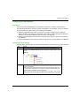
The technical characteristics of the devices described in this document also appear online. To
access this information online:
Step
Action
1
Go to the Schneider Electric home page www.schneider-electric.com.
2
In the Search box type the reference of a product or the name of a product range.
Do not include blank spaces in the model number/product range.
To get information on grouping similar modules, use asterisks (*).
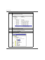
3
If you entered a reference, go to the Product Datasheets search results and click on the
reference that interests you.
If you entered the name of a product range, go to the Product Ranges search results and click
on the product range that interests you.
4
If more than one reference appears in the Products search results, click on the reference that
interests you.
5
Depending on the size of your screen, you may need to scroll down to see the data sheet.
6
To save or print a data sheet as a .pdf file, click Download XXX product datasheet.
The characteristics that are presented in this manual should be the same as those characteristics
that appear online. In line with our policy of constant improvement, we may revise content over time
to improve clarity and accuracy. If you see a difference between the manual and online information,
use the online information as your reference.
35010500 10/2014
9
Related Documents
10
Title of Documentation
Reference Number
Premium and Atrium Using Unity Pro, Ethernet Network Modules, User Manual
35006192 (Eng),
35006193 (Fre),
35006194 (Ger),
31007214 (Ita),
35006195 (Spa),
31007102 (Chs)
Premium and Atrium Using Unity Pro, Modbus Plus Network, User Manual
35006188 (Eng),
35006189 (Fre),
35006190 (Ger),
35013962 (Ita),
35006191 (Spa),
35013963 (Chs)
Premium and Atrium Using Unity Pro, Fipway Network, User Manual
35006183 (Eng),
35006185 (Fre),
35006186 (Ger),
35013955 (Ita),
35006187 (Spa),
35013956 (Chs)
Premium and Atrium Using Unity Pro, Fipio Bus, Setup Manual
35008155 (Eng),
35008156 (Fre),
35008157 (Ger),
35013953 (Ita),
35008158 (Spa),
35013954 (Chs)
Premium and Atrium Using Unity Pro, AS-i Bus, User Manual
35006196 (Eng),
35006197 (Fre),
35006198 (Ger),
35013927 (Ita),
35006201 (Spa),
35013928 (Chs)
Premium and Atrium Using Unity Pro, Asynchronous Serial Link, User Manual
35006178 (Eng),
35006179 (Fre),
35006180 (Ger),
35013959 (Ita),
35006181 (Spa),
35013960 (Chs)
35010500 10/2014
Title of Documentation
Reference Number
Modicon M340 for Ethernet, Communications Modules and Processors, User
Manual
31007131 (Eng),
31007132 (Fre),
31007133 (Ger),
31007494 (Ita),
31007134 (Spa),
31007493 (Chs)
AS-Interface Bus for Modicon M340, User Manual
EIO0000000138 (Eng),
EIO0000000139 (Fre),
EIO0000000140 (Ger),
EIO0000000142 (Ita),
EIO0000000141 (Spa),
EIO0000000143 (Chs)
Modicon M340 with Unity Pro, Serial Link, User Manual
35012430 (Eng),
35012432 (Fre),
35012431 (Ger),
35013363 (Ita),
35012433 (Spa),
35012434 (Chs)
Quantum with Unity Pro, TCP/IP Configuration, User Manual
33002467 (Eng),
33002468 (Fre),
33002469 (Ger),
31008078 (Ita),
33002470 (Spa),
31007110 (Chs)
Quantum with Unity Pro, Modbus Plus Network Modules, User Manual
35010487 (Eng),
35010488 (Fre),
35010489 (Ger),
35013961 (Ita),
35010490 (Spa),
35012186 (Chs)
Quantum with Unity Pro, 140 EIA 921 00 AS-I Bus Interface Module, User Manual 35012420 (Eng),
35012421 (Fre),
35012422 (Ger),
35013929 (Ita),
35012424 (Spa),
35013930 (Chs)
You can download these technical publications and other technical information from our website
at www.schneider-electric.com.
35010500 10/2014
11
12
35010500 10/2014
Modicon M340, Premium, Atrium, and Quantum Using Unity Pro
Introduction
35010500 10/2014
Part I
Introduction to the Communication Application
Introduction to the Communication Application
Subject of this Part
This part gives an overview of the communication application: the types of networks and buses,
services and architectures available.
What Is in This Part?
This part contains the following chapters:
Chapter
35010500 10/2014
Chapter Name
Page
1
General
15
2
Services Available on Networks and Buses
19
3
Interoperability
37
4
Communication Architectures
41
5
X-Way Message Routing
51
13
Introduction
14
35010500 10/2014
Modicon M340, Premium, Atrium, and Quantum Using Unity Pro
General
35010500 10/2014
Chapter 1
General
General
Subject of this Chapter
This chapter gives an overview of the different characteristics of the communication application.
What Is in This Chapter?
This chapter contains the following topics:
Topic
Page
Introduction to the Communication Application
16
Summary of Communication Solutions
18
35010500 10/2014
15
General
Introduction to the Communication Application
At a Glance
The communication application makes it possible to exchange data between different devices
connected to a bus or a network.
This function applies to :
processors with an Ethernet, Modbus, built-in Fipio or CANopen link,
specific rack-mounted communication modules,
the terminal port of a processor,
PCMCIA cards of a rack-mounted processor or module.
Communication Types
The different communication types are:
TCP/IP or Ethway Ethernet Network
Fipway Network
Modbus Plus Network
Fipio bus (manager and agent)
Uni-Telway bus
Modbus/JBus bus
Character mode serial link
CANopen field bus
Interbus field bus
Profibus field bus
The USB-standard fast terminal port
Available Services
The available services can be classified into three categories:
16
Explicit messaging (see page 28) services:
Modbus messaging
UNI-TE messaging
telegrams
Implicit database access services:
global data (see page 20)
common words (see page 27)
shared tables (see page 27)
Implicit Input/Output management services:
I/O scanning (see page 22)
peer cop (see page 24)
35010500 10/2014
General
WARNING
UNEXPECTED APPLICATION BEHAVIOR - DATA EXCHANGE COMPATIBILITY
Data structure alignments are not the same for Premium/Quantum and M340 PLCs so verify that
the data exchanged are compatible.
See the page DDT: Mapping rules (see Unity Pro, Program Languages and Structure, Reference
Manual ) for more information.
Failure to follow these instructions can result in death, serious injury, or equipment
damage.
Characteristics of the Different Service Types
The following table gives an overview of the main characteristics of the types of services mentioned
above:
Type of service
These services make it possible ...
They are used ...
Messaging services
for a device (Client) to send a
message to another device (Server)
and obtain a response without having
to program anything into the server
device.
to access data from time to
time.
Implicit database
access services
to share data which is refreshed
automatically and on a regular basis.
to synchronize applications or
to transparently obtain realtime images of a system on
several remote PLCs
Implicit I/O
management services
to transparently and automatically
manage remote I/Os on a network.
to monitor a set of distributed
systems across a network.
35010500 10/2014
17
General
Summary of Communication Solutions
At a Glance
The services presented earlier in this chapter are available for certain types of communication.
For example, for messaging services, certain communication functions apply to networks, others
to buses and others to serial links in character mode (see page 34).
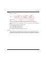
Summary
The following table gives an overview of the different services available according to the types of
communication:
Function
Fipway Fipio UniTelway
Character Modbus/ Modbus Ethway TCP/IP
mode
Jbus
Plus
CANopen USB
Messaging services
Communication
functions
The communication functions that can be used depend closely on the type of communication for which
they are applied (see page 34).
Implicit database access services
Global Data
-
-
-
-
-
-
-
X
-
-
Common
words
X
-
-
-
-
-
X
-
-
-
Shared
tables
X
-
-
-
-
-
X
-
-
-
Periodic
data
exchanges
-
X
-
-
-
-
-
-
-
-
-
-
-
-
-
-
X
-
-
Implicit I/O management services
I/O
Scanning
-
Peer cop
-
-
-
-
-
X
-
-
-
-
Other
-
X
-
-
-
X
-
-
X
-
Legend:
X
Yes
-
No
18
35010500 10/2014
Modicon M340, Premium, Atrium, and Quantum Using Unity Pro
Services
35010500 10/2014
Chapter 2
Services Available on Networks and Buses
Services Available on Networks and Buses
Subject of this Chapter
This chapter describes the different services available on the communication buses and networks.
What Is in This Chapter?
This chapter contains the following sections:
Section
Topic
Page
2.1
Global Data Service
20
2.2
IO Scanning Service
22
2.3
Peer Cop Service on Modbus Plus
24
2.4
Common Words and Shared Tables Services on Fipway
27
2.5
Messaging Service
28
35010500 10/2014
19
Services
Section 2.1
Global Data Service
Global Data Service
Global Data Service
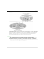
At a Glance
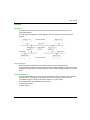
The aim of the Global Data service, which is supported by Ethernet modules, is to provide an
automatic data exchange for the coordination of PLC applications. Data is shared according to an
inter-device publication/subscription method.
How it Works
The communication modules are grouped into a Distribution group.
Each communication module publishes a local application variable for the other communication
modules in the distribution group.
Each communication module can also subscribe to the application variables published by all other
modules belonging to the distribution group.
The Global Data service should be configured to determine the location and the number of
application variables of each communication module. Once the modules have been configured,
exchanges between communication modules belonging to the same group are automatically
carried out when the PLC is in RUN mode.
20
35010500 10/2014
Services
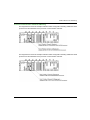
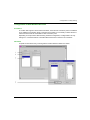
Illustration:
A Distribution group is a group of communication modules identified by the same multicast IP
address. Exchanges in "multicasting" are used to distribute Global Data. Several independent
distribution groups can co-exist on the same subnetwork with their own multicast address.
A Publication/Subscription protocol on UDP/IP is used for data distribution.
Limitations
There is no theoretical limit to the number of stations that may belong to a distribution group.
The main limitation is the number of variables exchanged in a group (64 variables).
Replacing a 140 NOE 771 x0 module by a new 140 NOE 771 x1 module, the Global Data
Service must not be configured by web pages. Otherwise, the Global Data Utility will start even
if Global Data has not been configured in the application.
35010500 10/2014
21
Services
Section 2.2
IO Scanning Service
IO Scanning Service
IO Scanning Service
At a Glance
The IO scanner makes it possible to periodically read or write to/from remote inputs/ouputs on the
Ethernet network, without requiring any specific programming.
This service comprises the following essential elements:
a read field containing all the values of the remote inputs,
a write field containing all the values of the remote outputs,
scanning periods independent of the PLC cycle and dedicated to checking each remote device.
How it Works
The scan will only be performed if the PLC is in Run mode.
This service works with all devices supporting Modbus communication on the TCP/IP profile in
server mode.
The exchange mechanism, which is transparent for users, involves:
22
read requests,
write requests,
read and write requests.
35010500 10/2014
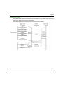
Services
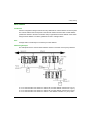
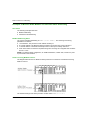
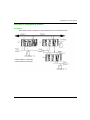
The following diagram shows how scanning of remote inputs/outputs works.
1. As soon as the PLC goes into Run mode, the module opens one connection per scanned
device.
2. The module then periodically reads the input words and periodically writes the output words of
each device.
3. If the PLC goes into Stop mode, the connections with each device are closed.
Summary of Functions
The functions of the IO scanning service are to:
manage the connection with each remote device (one connection per scanned device),
scan the inputs/outputs of the device by using the Modbus read/write requests on the TCP/IP
profile,
update the read/write fields in the application memory,
refresh the status bits of each remote device.
NOTE: The status bits indicate whether the input/output words of the module have been refreshed.
35010500 10/2014
23
Services
Section 2.3
Peer Cop Service on Modbus Plus
Peer Cop Service on Modbus Plus
Peer Cop Service
At a Glance
The Peer Cop service is a mechanism for automatic exchange between stations connected on the
same Modbus Plus segment.
This service makes it possible to control remote inputs / outputs on a continuous basis by implicit
exchanges.
Premium and Quantum PLCs are capable of managing this service on a Modbus Plus network
Premium PLCs support two types of Peer Cop transfer:
specific inputs,
specific outputs.
Specific Inputs and Outputs
Specific inputs and outputs are point-to-point services using the multicast (multi-station) protocol.
Each message contains one or more destination addresses for data transmission. This mode of
operation makes it possible to exchange data with several stations without them having to be
repeated.
Report
Three types of report are associated with specific inputs and outputs:
An activity bit provides information on the availability and validity of the status bits.
Status bits (one bit per station):
ensure consistency between the number of specific inputs configured and the number of
specific inputs received,
indicate if the specific inputs have been received before the Timeout.
Presence bits (one bit per station) indicate if the specific inputs have been refreshed.
NOTE: The presence bits are only valid for the specific inputs.
24
35010500 10/2014
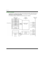
Services
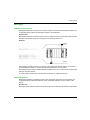
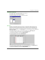
Example for the Inputs
The data blocks are copied in their entirety from the PCMCIA communication card to the internal
word space, reserved at the time of configuration.
In the following example, the address of the first internal word is %MW10:
35010500 10/2014
25
Services
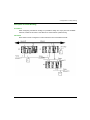
Example for the Outputs
The data blocks are copied in their entirety from the internal word space, reserved at the time of
configuration, to the PCMCIA communication card. The reports are copied from the PCMCIA
communication card to the language objects.
In the following example, the address of the first internal word is %MW10:
26
35010500 10/2014
Services
Section 2.4
Common Words and Shared Tables Services on Fipway
Common Words and Shared Tables Services on Fipway
Fipway Common Words and Shared Tables
At a Glance
The Fipway network provides two data sharing services:
common words,
shared table.
The main objective of these two services is to synchronize automation applications.
Common Words
The common words service consists of a set of dedicated %NW words. Each station on the network
can, depending on its software configuration, access the database in read or write mode.
Updates are performed implicitly at the start of the cycle for read operations and at the end of the
cycle for write operations. The function of the application program is simply to read or write these
words.
The addressing of the words is as follows: %NWn.s.k
The following table states the address parameters of the common words:
Parameter
Description
n
Network number
s
Station number
k
Word number
NOTE: The network number makes it possible to select the network on which the common words
are exchanged in a multi-network configuration.
Shared Table
This service makes it possible to exchange a table of %MW internal words divided up into as many
fields as there are stations on the Fipway network. The principle is based on each PLC
broadcasting a word memory field to the other stations on the network.
Updates are performed implicitly and independently of the application program’s execution cycle.
The function of the program is simply to write or read the %MW words.
NOTE: When configuring and assigning fields, be careful to avoid creating memory conflicts
between stations.
35010500 10/2014
27
Services
Section 2.5
Messaging Service
Messaging Service
Subject of This Section
This section gives an overview of the messaging service available on Schneider Electric PLCs.
What Is in This Section?
This section contains the following topics:
Topic
28
Page
Messaging Service
29
Characteristics of the Messaging Service Communication Functions
30
35010500 10/2014
Services
Messaging Service
At a Glance
The messaging service makes it possible to perform inter-PLC data exchanges using
communication functions.
Two types of messaging are used:
Private: UNI-TE on Modicon Premium and Telemecanique installed base,
Standard: Modbus on Modicon Quantum, Modicon Premium, Modicon M340, Modicon M580,
and Modicon installed base.
The destination entities of an exchange can either be located in a local station or in a remote station
on a communication channel or directly in the CPU.
The communication functions provide an interface that is independent of the location of the
destination entity. Furthermore, they mask the coding of the communication requests from the
user. They thus provide compatibility of communication between Premium, Micro, Quantum,
TSX 40, TSX 17, 1000 series and Modicon M340 PLCs.
NOTE: Processing of communication functions is asynchronous in relation to the processing of the
application task which allowed them to be activated. The send/receive telegram and stop operation
functions are the only exceptions as their execution is synchronous with the execution of the
activation task.
Synchronous/Asynchronous Communication
A communication function is said to be synchronous when it is wholly executed during the PLC task
that activated it.
A communication function is said to be asynchronous when it is executed during one or more PLC
tasks after the task that activated it.
35010500 10/2014
29
Services
Characteristics of the Messaging Service Communication Functions
At a Glance
These functions (see Unity Pro, Communication, Block Library) enable communication between
one device and another. Certain functions are common to several types of communication channel.
Others may be specific to one communication function.
NOTE: Processing of communication functions is asynchronous in relation to the processing of the
application task, which allowed them to be activated. The send/receive telegram and stop
operation functions are the only exceptions as their execution is synchronous with the execution
of the activation task.
NOTE: It is recommended that asynchronous functions be triggered on edge and not on state to
avoid sending several identical requests in quick succession, thus saturating the communication
buffers.
Messaging Service Communication Functions on Modicon M340 Platform
The following table gives an overview of Modicon M340 platform messaging service functions:
30
Function
Role
DATA_EXCH
Transmit or receive data.
ETH_PORT_CTRL
Activate or deactivate a protocol.
INPUT_BYTE
Receive an array of bytes on a character mode link of a BMX NOM module in a
local rack or linked to a CPU embedded communication channel.
INPUT_CHAR
Receive a character string on a character mode link of a BMX NOM module in
a local rack or linked to a CPU embedded communication channel.
PRINT_CHAR
Send a character string on a character mode link of a BMX NOM module in a
local rack or linked to a CPU embedded communication channel.
READ_VAR
Read the value of one or more language objects via a communication module
in a local rack or linked to a CPU embedded communication channel.
SEND_EMAIL
Send an email over an Ethernet port of a communication module plugged in a
local rack.
WRITE_VAR
Write the value of one or more language objects via a communication module
in a local rack or linked to a CPU embedded communication channel.
35010500 10/2014
Services
Messaging Service Communication Functions on Modicon M580 Platform
The following table gives an overview of the Modicon M580 platform messaging service functions:
Function
Role
DATA_EXCH
End any requests (Modbus, Umas …) to any Modbus slave via a
communication module plugged in a local rack or in an EIO drop.
GET_TS_EVT_M
Get the time stamped data in a Modicon BMX ERT 1604T or BMX CRA •••••
module plugged in a local rack or in an EIO drop.
INPUT_BYTE
Receive an array of bytes on a character mode link of a BMX NOM module
plugged in a local rack or in an EIO drop.
INPUT_CHAR
Receive a character string on a character mode link of a BMX NOM module
plugged in a local rack or in an EIO drop.
PRINT_CHAR
Send a character string on a character mode link of a BMX NOM module
plugged in a local rack or in an EIO drop.
READ_PARAM_MX
Read the parameter words of an X80 I/O module plugged in a local rack by
performing an explicit exchange.
READ_STS_MX
Read the status words of an X80 I/O module plugged in a local rack or in an EIO
drop by performing an explicit exchange.
READ_VAR
Read the value of one or more language objects via a communication module
plugged in a local rack or in an EIO drop.
RESTORE_PARAM_MX
Restore the parameter words of an X80 I/O module plugged in a local rack by
performing an explicit exchange.
SAVE_PARAM_MX
Save the parameter words of an X80 I/O module plugged in a local rack by
performing an explicit exchange.
SEND_EMAIL
Send an email over an Ethernet port of a communication module plugged in a
local rack (Ethernet modules cannot be plugged in an EIO drop).
WRITE_CMD_MX
Send a command to an X80 I/O module plugged in a local rack or in an EIO drop
by performing an explicit exchange.
WRITE_PARAM_MX
Write the parameter words of an X80 I/O module plugged in a local rack by
performing an explicit exchange.
WRITE_VAR
Write the value of one or more language objects via a communication module
plugged in a local rack or in an EIO drop.
35010500 10/2014
31
Services
Messaging Service Communication Functions on Modicon Quantum Platform
The following table gives an overview of Modicon Quantum platform messaging service functions:
Function
Role
CREAD_REG
Continuously read a register area from a slave addressed via Modbus Plus,
TCP/IP-Ethernet or SY/MAX-Ethernet
CWRITE_REG
Continuously write a register area to a slave addressed via Modbus Plus,
TCP/IP-Ethernet or SY/MAX-Ethernet
EXCH_QX
Perform data transfers through an EIO bus to and from Modbus slaves
connected to a Modicon M340 rack
INPUT_CHAR_QX
Receive a character string from a Modicon M340 serial communication module
through an EIO bus
MBP_MSTR
Perform various network communication operations on Modbus Plus, TCP/IPEthernet or SY/MAX-Ethernet
PRINT_CHAR_QX
Send a character string of 1000 bytes maximum from a Modicon M340 Modbus
master through an EIO bus
READ_REG
Read a register area from a slave addressed via Modbus Plus, TCP/IP-Ethernet
or SY/MAX-Ethernet
READ_REG_QX
Read registers in a Modbus slave connected to a Modicon M340 Modbus
master through an EIO bus
READ_STS_QX
Read the status words of a Modicon M340 Ethernet I/O module by performing
an explicit exchange with the processor memory
WRITE_CMD_QX
Send a command to a Modicon M340 Ethernet I/O module with a command
word by performing an explicit exchange
WRITE_REG
Write a register area to a slave addressed via Modbus Plus, TCP/IP-Ethernet or
SY/MAX-Ethernet
WRITE_REG_QX
Write registers in a Modbus slave connected to a Modicon M340 Modbus
master through an EIO bus
XXMIT
Modbus messages from master PLC and ASCII input/output strings.
Messaging Service Communication Functions on Modicon Momentum Platform
The following table gives an overview of Modicon Momentum platform messaging service
functions:
32
Function
Role
MBP_MSTR
Perform various network communication operations on Modbus Plus, TCP/IPEthernet or SY/MAX-Ethernet.
XMIT
Modbus messages from master PLC and ASCII input/output strings.
XXMIT
Modbus messages from master PLC and ASCII input/output strings.
35010500 10/2014
Services
Messaging Service Communication Functions on Modicon Premium Platform
The following table gives an overview of Modicon Premium platform messaging service functions:
Function
Role
DATA_EXCH
Send/request receipt of data.
INPUT_BYTE
Read an array of bytes.
INPUT_CHAR
Read a character string.
OUT_IN_CHAR
Send a character string and wait for a response.
OUT_IN_MBUS
Emulate a Modbus master communication from a serial link configured in
character mode.
PRINT_CHAR
Write a character string.
RCV_TLG
Receive a telegram.
READ_ASYN
Read 1 Kbyte of messaging.
READ_GDATA
Read common Modbus Plus data.
READ_VAR
Read standard language objects: internal words and bits, system words and
bits, timers, monostables, drums, registers, counters.
SEND_REQ
Send UNI-TE requests.
SEND_TLG
Send a telegram.
UNITE_SERVER
Process immediately READ_VAR and WRITE_VAR requests on Modbus
(Immediate server).
WRITE_ASYN
Write 1 Kbytes of messaging.
WRITE_GDATA
Write common Modbus Plus data.
WRITE_VAR
Write standard language objects: internal words and bits, system words and
bits.
35010500 10/2014
33
Services
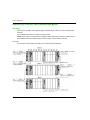
Availability of Functions According to Protocols
Protocols supported by the messaging service functions in a Modicon M340 platform:
Function
TCP/IP
ETHWAY
X
X
–
–
–
Fipio Character
mode
DATA_EXCH
X
ETH_PORT_CTRL
X
–
–
–
–
–
–
–
–
INPUT_BYTE
–
–
–
–
–
–
–
–
X
INPUT_CHAR
–
–
–
–
–
–
–
–
X
PRINT_CHAR
–
–
–
–
–
–
–
–
X
READ_VAR
X
–
X
X
–
–
–
–
–
SEND_EMAIL
–
–
–
–
–
–
–
–
X
WRITE_VAR
X
–
X
X
–
–
–
–
–
X
–
–
CANopen Modbus Modbus Fipway Uniserial
Plus
Telway
–
X
Yes
No
Protocols supported by the messaging service functions in a Modicon M580 platform:
Function
TCP/IP ETHWAY CANopen Modbus Modbus Fipway UniFipio Character
serial
Plus
Telway
mode
DATA_EXCH
X
–
–
X
–
–
–
–
–
GET_TS_EVENT_M
X
–
–
–
–
–
–
–
–
INPUT_BYTE
–
–
–
–
–
–
–
–
X
INPUT_CHAR
–
–
–
–
–
–
–
–
X
PRINT_CHAR
–
–
–
–
–
–
–
–
X
READ_PARAM_MX
X
–
–
–
–
–
–
–
–
READ_STS_MX
X
–
–
–
–
–
–
–
–
READ_VAR
X
–
–
X
–
–
–
–
–
RESTORE_PARAM_MX
X
–
–
–
–
–
–
–
–
SAVE_PARAM_MX
X
–
–
–
–
–
–
–
–
SEND_EMAIL
X
–
–
–
–
–
–
–
–
WRITE_CMD_MX
X
–
–
–
–
–
–
–
–
WRITE_PARAM_MX
X
–
–
–
–
–
–
–
–
WRITE_VAR
X
–
–
X
–
–
–
–
–
X
–
34
Yes
No
35010500 10/2014
Services
Protocols supported by the messaging service functions in a Modicon Quantum platform:
Function
TCP/IP
ETHWAY
CANopen Modbus Modbus Fipway Uniserial
Plus
Telway
Fipio Character
mode
CREAD_REG
X
–
–
–
X
–
–
–
–
CWRITE_REG
X
–
–
–
X
–
–
–
–
EXCH_QX
X
–
–
X
–
–
–
–
–
INPUT_CHAR_QX
–
–
–
–
–
–
–
–
X
MBP_MSTR
X
–
–
–
X
–
–
–
–
PRINT_CHAR_QX
–
–
–
–
–
–
–
–
X
READ_REG
X
–
–
–
X
–
–
–
–
READ_REG_QX
–
–
–
X
–
–
–
–
–
READ_STS_QX
X
–
–
–
–
–
–
–
–
WRITE_CMD_QX
X
–
–
–
–
–
–
–
–
WRITE_REG
X
–
–
–
X
–
–
–
–
WRITE_REG_QX
–
–
–
X
–
–
–
–
–
XXMIT
–
–
–
X
–
–
–
–
X
X
–
Yes
No
Protocols supported by the messaging service functions in a Modicon Momentum platform:
Function
TCP/IP
ETHWAY
CANopen Modbus Modbus Fipway Uniserial
Plus
Telway
Fipio Character
mode
MBP_MSTR
X
–
–
–
X
–
–
–
–
XMIT
–
–
–
X
–
–
–
–
X
XXMIT
–
–
–
X
–
–
–
–
X
X
–
Yes
No
35010500 10/2014
35
Services
Protocols supported by the messaging service functions in a Modicon Premium platform:
Function
TCP/IP
ETHWAY
CANopen Modbus Modbus Fipway Uniserial
Plus
Telway
Fipio Character
mode
(1)
X
–
–
–
X
X
–
–
INPUT_BYTE
–
–
–
–
–
–
–
–
X
INPUT_CHAR
X
X
–
–
–
X
–
–
X
OUT_IN_CHAR
X
X
–
–
–
X
–
–
X
DATA_EXCH
OUT_IN_MBUS
–
–
–
X
–
–
–
–
–
PRINT_CHAR
X
X
–
–
–
X
–
–
X
RCV_TLG
–
–
–
–
–
X
–
–
–
READ_ASYN
X
–
–
–
–
–
–
–
–
READ_GDATA
–
–
–
–
X
–
–
–
–
READ_VAR
X
X
–
X
X
X
X
X
–
SEND_REQ
X
X
X
X
X
X
X
X
–
SEND_TLG
–
–
–
–
–
X
–
–
–
UNITE_SERVER
–
–
–
X
–
–
–
–
–
WRITE_ASYN
X
–
–
–
–
–
–
–
–
WRITE_GDATA
–
–
–
–
X
–
–
–
–
WRITE_VAR
X
X
–
X
X
X
X
X
–
X Yes
– No
(1) Exchanges between applications and UNI-TE requests are available but Modbus requests coding is not available
with an ETY Premium module.
36
35010500 10/2014
Modicon M340, Premium, Atrium, and Quantum Using Unity Pro
Interoperability
35010500 10/2014
Chapter 3
Interoperability
Interoperability
List of Modbus Function Codes
At a Glance
Quantum, Premium and M340 PLCs have communication server kernels that accept the common
Modbus function codes. These are listed in the table on this page.
As servers, Quantum, Premium and M340 PLCs recognize all Class 0 and Class 1 Modbus
function codes, as stipulated in the Modbus specifications available at
http://www.Modbus.org. Their server kernel also includes the function code 23 for
reading/writing of consecutive variables.
For the list of Modbus function codes recognized by Quantum PLCs, please refer to the specific
Quantum documentation.
For the list of function codes recognized by Premium PLCs, please refer to the specific Premium
(see Premium and Atrium using Unity Pro, Asynchronous Serial Link, User Manual)
documentation. In addition to this, Premium PLCs recognize certain UNI-TE (see Unity Pro,
Communication, Block Library) requests.
35010500 10/2014
37
Interoperability
List of Modbus Requests Recognized When Connected as a Server
The following table lists the function codes and the address of the Modbus function codes,
recognized by Premium, Quantum and M340 platforms.
Function
code
Quantum
memory
address
M340 and
Premium
memory
address
Meaning
1
16#0XXX
%M
Read output bits, refer to note below.
2
16#1XXX
%M
Read input bits
3
16#4XXX
%MW
Read consecutive integer values (until 125
registers for Premium/Atrium PLCs)
4
16#3XXX
%MW
Read consecutive input integer values (until
124 registers for Premium/Atrium PLCs)
5
16#0XXX
%M
Write single output bit
6
16#4XXX
%MW
Write single integer value
151
16#0XXX
%M
Write n output bits
161
16#4XXX
%MW
Write consecutive integer values
2
16#4XXX
%MW
Read/write consecutive integer values3
23
1When using the SEND_REQ communication function to send these codes, the maximum size that
can be used is 121 words (1936 bits).
2This
function is neither supported nor transmitted by Premium TSX SCP 111, TSX SCP 114 and
TSX SCP 1114 communication cards nor by TSX SCY 116 01 and TSX SCY 21601
communication modules.
3On
the Premium platform, the Read is done before the Write.
NOTE:
The READ_VAR communication function can read, on any remote devices, up to:
1008 consecutive bits for Premium CPUs.
2000 consecutive bits for M340 CPUs.
NOTE: To be able to read more than these limitations, the SEND_REQ communication function
must be used.
38
35010500 10/2014
Interoperability
Use of Modbus Function Codes as a Client on Premium and M340
The table below lists the Modbus function codes and their use as a client on Premium, Quantum
and M340 PLCs.
Function Quantum
code
memory
address
M340 and
Premium
memory
address
Modbus request
Communication
function
1
16#0XXX
%M
Read output bits
READ_VAR
2
-
%I
Read input bits, see 1)
READ_VAR
3
16#4XXX
%MW
Read consecutive integer values
(until 125 registers for
Premium/Atrium PLCs)
READ_VAR
4
-
%IW
Read consecutive input integer
values (until 124 registers for
Premium/Atrium PLCs), see 1)
READ_VAR
SEND_RER for
Premium/Atrium
PLCs
15
16#0XXX
%M
Write n output bits
WRITE_VAR
16
16#4XXX
%MW
Write consecutive integer values
WRITE_VAR
1) The addresses %I and %IW cannot be used when creating a communication function of type
READ_VAR with the function input assistant.
The way in which to use function codes with communication functions is described in the Modbus
manual (see Premium and Atrium using Unity Pro, Asynchronous Serial Link, User Manual).
NOTE: Interoperability with Windows applications is provided by access to the PLC variables using
OFS software.
WARNING
UNEXPECTED APPLICATION BEHAVIOR - DATA EXCHANGE COMPATIBILITY
Data structure alignments are not the same for Premium/Quantum and M340 PLCs so verify that
the data exchanged are compatible.
See the page DDT: Mapping rules (see Unity Pro, Program Languages and Structure, Reference
Manual ) for more information.
Failure to follow these instructions can result in death, serious injury, or equipment
damage.
35010500 10/2014
39
Interoperability
40
35010500 10/2014
Modicon M340, Premium, Atrium, and Quantum Using Unity Pro
Communication Architectures
35010500 10/2014
Chapter 4
Communication Architectures
Communication Architectures
Subject of this Chapter
This chapter gives an overview of the different communication architectures.
What Is in This Chapter?
This chapter contains the following topics:
Topic
Page
Global Architecture
42
Network Architectures
46
Fieldbus
50
35010500 10/2014
41
Communication Architectures
Global Architecture
At a Glance
Schneider has a communications strategy based on open standards (core of the range) such as:
Ethernet Modbus TCP/IP
CANopen
AS-Interface
Modbus Link Series
This has not always been the case and there are a significant number of installed bases on
networks or proprietary buses such as Modbus Plus, Fipway, Ethway, X-Way on TCP/IP, Fipio,
Symax and Uni-telway.
Schneider offers a connectivity range for the main standards available on the market through its
Profibus, Interbus and TCPopen ranges.
The possible and recommended communication architectures are presented in the following
pages, according to the type of PLC used:
At level 2: Inter-PLC network (see page 46),
At level 1: Field Bus (see page 50).
The communication solutions for existing installations, from the Telemecanique or Modicon
ranges, are then presented.
42
35010500 10/2014
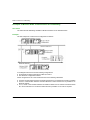
Communication Architectures
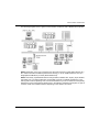
Global Architecture
The following diagram shows a global communication architecture with an AS-i bus:
35010500 10/2014
43
Communication Architectures
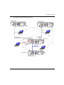
The following diagram shows a global communication architecture with a Modbus and Uni-Telway
bus:
44
35010500 10/2014
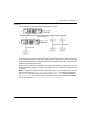
Communication Architectures
The following diagram shows a global communication architecture with a Modbus and Fipio bus:
NOTE: Depending on the type of network used, the interconnection is made either directly via a
PLC which routes the information (Ethernet/Uni-Telway), or via an additional device such as a
bridge (Ethernet/Modbus) or switch (Ethernet/Ethernet).
NOTE: Technically, sophisticated solutions using Ethernet, Modbus Plus, Fipway, Fipio, Modbus,
Uni-Telway etc. in a single architecture are possible. However, to facilitate maintenance, user
training and to reduce operating costs, it is recommended that you aim for maximum homogeneity
between the types of networks and buses used. In the following architecture examples, we give an
overview of the most suitable solutions depending on the devices connected.
35010500 10/2014
45
Communication Architectures
Network Architectures
At a Glance
Various network architectures are available. The Schneider product range enables you to create
standard Ethernet mono-networks as well as transparent multi-network architectures
(Ethernet/Fipway/Modbus Plus). The following examples of network architectures show the
various optimal solutions provided by Schneider products.
NOTE: The selection of an architecture with the Modbus Plus network or Fipway network is
strongly linked to the use of Quantum or Premium devices:
Modbus Plus for Quantum and Premium PLCs,
Fipway for Premium PLCs.
NOTE: In the following illustrations, the arrows show the different communication possibilities.
NOTE: An attempt has been made to show all the available scenarios.
NOTE: The types of communication shown in the homogeneous Ethernet networks are also
possible when these networks are extended using Modbus Plus or Fipway segments.
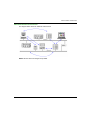
Mono-Network Ethernet Architecture
The diagram below shows an Ethernet mono-network:
NOTE: All inter-device exchanges are possible.
46
35010500 10/2014
Communication Architectures
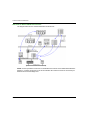
Multi-Network Ethernet Architecture
The diagram below shows an Ethernet multi-network:
NOTE: All inter-device exchanges are possible.
35010500 10/2014
47
Communication Architectures
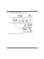
Multi-Network Ethernet/Modbus Architecture
The diagram below shows an Ethernet/Modbus multi-network:
NOTE: Access is possible from devices on the Modbus Plus network across Ethernet/Modbus Plus
bridges. In contrast, the devices on the second Modbus Plus network cannot be accessed by an
Ethernet device via the Bridge Plus.
48
35010500 10/2014
Communication Architectures
Multi-Network Ethernet/Fipway Architecture
The diagram below shows an Ethernet/Fipway multi-network:
NOTE: All inter-device exchanges are possible.
35010500 10/2014
49
Communication Architectures
Fieldbus
At a Glance
The CPU uses many types of fieldbus: Ethernet, CANopen, Modbus, Modbus Plus, AS-i, Fipway,
Uni-Telway, Fipio, INTERBUS, and PROFIBUS.
Field buses addressed by each platform:
Fieldbus
M340
M580
Ethernet
X*, O
X, O
X*, O
X*
X*, O
CANopen
X*
–
–
O
O
Modbus
X, O
O
X
X
O
Modbus Plus
O*
O*
X
O
O
Quantum
Momentum
Premium
AS-i
O
O
O
–
O
Fipway
–
–
–
–
O
Uni-Telway
–
–
–
–
X, O
Fipio
–
–
–
O
X*
INTERBUS
–
–
O
O
O
PROFIBUS
O*
O*
O, O*
O
O, O*
X
X*
O
O*
–
50
Platform
Embedded in the CPU.
Embedded is some CPUs.
Available through extension modules (inserted in the CPU or added in a rack).
Communication is performed using a gateway connected to the Ethernet distributed network
addressed by the CPU or by an Ethernet module.
Not available.
35010500 10/2014
Modicon M340, Premium, Atrium, and Quantum Using Unity Pro
X-Way Routing
35010500 10/2014
Chapter 5
X-Way Message Routing
X-Way Message Routing
Subject of this Chapter
This chapter describes the principles of X-Way message routing on X-Way multi-network
architectures.
What Is in This Chapter?
This chapter contains the following topics:
Topic
Page
General
52
Features
53
Main Address
55
Multi-Module Station Addresses
56
Messaging
57
35010500 10/2014
51
X-Way Routing
General
Introduction
A multi-network architecture consists of several networks. Two levels of architecture are
distinguished:
Multi-module architectures, in which there are several networks but no communication between
these different segments is provided by the communication system.
Multi-network architectures, composed of several network segments interconnected by bridge
stations. Communication transparency is then provided in the equipment group present in this
type of architecture.
This chapter describes how to set up the bridge function in a Premium PLC station, as well as the
use of communication services in a multi-network architecture. The multi-network architecture
complies with X-Way communication standards.
To set up stations on different networks, refer to the documentation corresponding to the module
used.
NOTE: X-Way communication is not available for Modicon M340 PLCs.
52
35010500 10/2014
X-Way Routing
Features
At a Glance
An X-Way PLC architecture is comprised of various network levels that interconnect via
intermediate stations.
In a multi-network architecture, a single logic link must exist between two terminal stations.
Example
Terminal Stations
A terminal station is addressed by the {network address . station address} pairing.
Terminal stations receive the messages intended for their network address, as well as the general
broadcast messages, and send to their network connection all the messages intended for a remote
station.
Intermediate Stations
An intermediate station has as many network addresses as it has connection points to different
networks. One of its addresses is considered to be the main address and has the role of
guaranteeing access to all the communication entities of a routing station.
Intermediate stations are classified in two categories:
Multicoupler stations
Bridge stations
35010500 10/2014
53
X-Way Routing
Multicoupler Stations
These provide management of various network couplers and guarantee all the mono-network
services on the various network segments (common words, telegrams, messaging). They do not
offer routing between the various network connections.
Bridge Stations
These provide the same functions as the multi-coupler stations and also guarantee transparency
of communication between the various network connections.
54
35010500 10/2014
X-Way Routing
Main Address
Introduction
A station configured in bridge mode has as many addresses as it does network connection points.
The network address that corresponds to the network module with the lowest module address
(module the farthest to the left in the station rack) is regarded as the main address of the station.
Using the main address of a station guarantees access to a bridge station.
Rule
A bridge station must always be accessed by its main address.
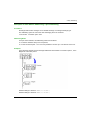
Addressing Example
The example shows the communication between stations connected on the Fipway networks.
For a communication from station A to station R2, the main address of station R2 is {11.3}.
For a communication from station A to station R1, the main address of station R1 is {12.7}.
For a communication from station A to station R3, the main address of station R3 is {13.5}.
For a communication from station A to station C, the address of station C is {12.7}5.0.56.
35010500 10/2014
55
X-Way Routing
Multi-Module Station Addresses
Introduction
A station configured in multi-module mode has as many addresses as it does network connection
points.
There is no main address for the station. It will be addressed according to the network that
communicates with it.
Rule
A multi-module station must always be accessed via the network address that corresponds to the
network module enabling entry to the station.
Example
In the following example, station R1 does not have the bridge function between its modules 2, 4
and 5.
56
For a communication from station A to station R1, the address is {13.5}SYS.
For a communication from station B to station R1, the address is {12.7}SYS.
35010500 10/2014
X-Way Routing
Messaging
With Multi-Coupler Stations
Messages intended for a network are sent to the coupler connected to the destination network. The
configuration phase allows the destination coupler to be determined.
Specific case
Messages intended for a network with an unknown address are sent to the network with the main
address of the station, along with messages whose network number is 0.
Example:
All messages intended for network 3 are sent to the coupler with module address 4, and those
whose destination network is 1 to the network link integrated into the processor.
All messages whose network number address is different from 1 or 3 are sent to the processor that
manages the main network.
In a multi-coupler architecture, communication is limited to a single network level.
With Bridge Stations
Messages intended for a network are sent to the coupler that has access to this network. The
configuration phase allows determination of the accessible networks for each coupler of the
station.
Specific case
Messages whose network number is 0 are sent to the network with the main address of the station.
35010500 10/2014
57
X-Way Routing
58
35010500 10/2014
Modicon M340, Premium, Atrium, and Quantum Using Unity Pro
Addressing
35010500 10/2014
Part II
Addressing
Addressing
Subject of this Part
This part describes the different addressing solutions for devices on a communication bus or
network.
What Is in This Part?
This part contains the following chapters:
Chapter
Chapter Name
Page
6
General Points Concerning Addressing
61
7
IP Addressing
63
8
Modbus Plus Addressing
67
X-Way Addressing
71
10
9
Modicon M340 PLCs Addressing
85
11
General points concerning bridging
99
35010500 10/2014
59
Addressing
60
35010500 10/2014
Modicon M340, Premium, Atrium, and Quantum Using Unity Pro
Introduction to Addressing
35010500 10/2014
Chapter 6
General Points Concerning Addressing
General Points Concerning Addressing
General
At a Glance
Within a communication architecture, each device must be identified by an address. This address
is specific to each device, and enables the device initiating communication to determine the
destination precisely. Similarly, for the configuration of services such as Global Data on Ethernet,
the Peer Cop service on Modbus Plus or common words and shared tables on Fipway, these
addresses make it possible to identify the stations that own different shared information.
Schneider products support 4 types of addressing depending on the type of device, network or bus
used:
IP addressing (see page 63),
Modbus Plus addressing (see page 67),
X-Way addressing (see page 71),
Modicon M340 PLCs addressing (see page 85)
35010500 10/2014
61
Introduction to Addressing
62
35010500 10/2014
Modicon M340, Premium, Atrium, and Quantum Using Unity Pro
IP Addressing
35010500 10/2014
Chapter 7
IP Addressing
IP Addressing
Note on IP Addressing
IP Address
On a TCP/IP Ethernet network, each device must have a unique IP address.This address is made
up of two identifiers, one of which identifies the network, while the other identifies the connected
machine.
The uniqueness of the addresses is managed as follows:
When the network environment is of open type, the uniqueness of the address is guaranteed by
the attribution of a network identifier by the relevant authority in the country where the network
is located,
If the type of environment is closed, the uniqueness of the address is managed by the
company’s network manager.
An IP address is defined as 32 bits. It consists of 4 numbers, one for each byte of the address.
NOTE: Standardized and made common largely thanks to the Internet, IP addressing is described
in detail in RFCs (Request For Comment) 1340 and 791 which stipulate the Internet standards as
well as in computing manuals describing networks. You can refer to these sources for further
information.
Example
Depending on the size of the network, three classes of address can be used:
35010500 10/2014
63
IP Addressing
Spaces reserved for the different classes of IP addresses:
Class
Range
A
0.0.0.0 to 127.255.255.255
B
128.0.0.0 to 191.255.255.255
C
192.0.0.0 to 223.255.255.255
Class A addresses are intended for large-scale networks which have a large number of
connected sites.
Class B addresses are intended for medium-scale networks which have fewer connected sites.
Class C addresses are intended for small-scale networks which have a small number of
connected sites.
Sub-Addressing and Sub-Network Mask
An IP address is composed of two identifiers, one of which identifies the network while the other
identifies the connected machine. In reality, the machine identifier can also hold a sub-network
identifier.
In an open environment, having received a network identifier from the relevant authority, the local
system administrator has the possibility of managing many networks. This means that local
networks can be installed without having any effect on the external world, which still sees just one
network designated by the network identifier.
The sub-network mask makes it possible to see the number of bits attributed respectively to the
network identifier and to the sub-network identifier (bits at 1), and then to the machine identifier
(bits at 0).
64
35010500 10/2014
IP Addressing
Example
Example: 140.186.90.3
The segmentation allows for 254 possible sub-networks with 254 sub-network machines.
The value of the sub-network mask should be chosen so that it is consistent with the IP address
class.
The sub-network mask will have the following value:
for a class A address: 255.xxx.xxx.xxx,
for a class B address: 255.255.xxx.xxx,
for a class C address: 255.255.255.xxx,
xxx is an arbitrary value which can be chosen by the user.
Gateway
The term Gateway is used in this manual in the sense of "router". If the target machine is not
connected to the local network, the message will be sent to the "default gateway" connected to the
local network, which will guarantee routing to another gateway or towards its final destination.
35010500 10/2014
65
IP Addressing
66
35010500 10/2014
Modicon M340, Premium, Atrium, and Quantum Using Unity Pro
Modbus Plus Addressing
35010500 10/2014
Chapter 8
Modbus Plus Addressing
Modbus Plus Addressing
Addressing for a Modbus Plus Communication Entity
At a Glance
Modbus Plus addressing makes it possible to identify a device on a Modbus Plus network.
The Modbus Plus addressing system is based on the access path that needs to be followed to
reach the destination device. This path is determined by the Modbus Plus routers, also referred to
as Bridges Plus. So when a device has to communicate with another device, it is necessary to
determine the path taken by the data to be communicated.
Principle
A Modbus Plus network segment may have up to 64 addressable devices. Each device has a
unique address between 1 and 64.
Several segments may be linked by Bridges Plus.
The routing path is determined by the 5 bytes that indicate in succession the addresses of the
devices that need to be crossed before arriving at the destination.
The routing system makes it possible to cross a maximum of 3 segments, in other words to allow
communication between stations belonging to 5 consecutive segments.
NOTE: When not all of the 5 bytes are necessary (only one Bridge Plus crossed for example), the
remaining bytes are set to 0.
35010500 10/2014
67
Modbus Plus Addressing
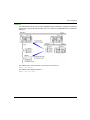
Illustration
The following illustration shows a multi-segment Modbus Plus structure. Three characteristic
examples are used to explain Modbus Plus addressing:
Example 1
The routing path to access the Quantum station is:
61, 30, 22, 62, 0.
NOTE: The final 0 is added so that the address path consists of 5 bytes.
68
35010500 10/2014
Modbus Plus Addressing
Example 2
The routing path to access slave A is as follows:
61, 25, 1, 0, 0.
NOTE: As slave A is the only slave on port 1, it is sufficient to indicate the port number and
complete the path with the zeros to obtain the 5 bytes for the address path.
Example 3
The routing path to access slave 113 is as follows:
61, 25, 4, 113, 0.
NOTE: When several slaves are connected to the same port, it is necessary to indicate the slave
number after the port number. Do not forget to complete the address with zeros to obtain 5 bytes.
35010500 10/2014
69
Modbus Plus Addressing
70
35010500 10/2014
Modicon M340, Premium, Atrium, and Quantum Using Unity Pro
X-Way Addressing
35010500 10/2014
Chapter 9
X-Way Addressing
X-Way Addressing
Subject of this Chapter
This chapter describes X-Way addressing and indicates its fields of application.
What Is in This Chapter?
This chapter contains the following topics:
Topic
Page
Addressing for a Communication Entity
72
Types of Communication Entities
74
Processor Communication Channel Addressing
76
Addressing for a TSX SCY 21601 Communication Module
78
Examples of Intra-Station Addressing: Uni-Telway Addressing
79
Examples of Intra-Station Addressing: Fipio Addressing
81
Examples of Intra-Station Addressing
82
35010500 10/2014
71
X-Way Addressing
Addressing for a Communication Entity
At a Glance
X-Way addressing makes it possible to identify a communication entity on a network or a bus, or
on a station’s bus on a network. Each station is identified by a unique address, which consists of
a network number and a station number. The addresses then differ according to the bus:
Uni-Telway or Modbus bus
Fipio bus
Within a station, each communication entity is characterized by a topological address (access
path) and a type (see page 74).
NOTE: An address is expressed in the form of a character string. However, it can only be used in
conjunction with the function ADDR(), which is why the following notation will be used to describe
an address: ADDR(‘address string’);
Addressing a Station on a Network
The address of a station on a network takes the form: ADDR(‘{n.s}SYS’)
where:
n: network number (network)
s: station number (station
SYS: keyword used to stipulate the station server system (see page 74)
Addressing a Device on a Uni-Telway or Modbus Bus
The address of a device on a Uni-Telway or Modbus bus depends on the station managing the bus:
stand-alone station: ADDR(‘r.m.c.e’)
station belonging to a network: ADDR(‘{n.s}r.m.c.e’)
where:
n: network number (network)
s: station number (station)
r: rack number (rack)
m: module number (module)
c: channel number (channel)
e: number of device or slave (equipment)
72
35010500 10/2014
X-Way Addressing
Addressing of a Device on a Fipio Bus
The address of a device on a Fipio bus depends on the station managing the bus:
stand-alone station: ADDR(‘\b.e\SYS’)
station belonging to a network: ADDR(‘{n.s}\b.e\SYS’)
where:
n: network number (network)
s: station number (station)
b: bus number (bus), for Fipio the bus number is always 2
e: device number (equipment)
SYS: keyword used to stipulate the station server system (see page 74)
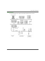
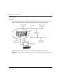
Example
The figure below describes the address of the station located in the gray rectangle. The example
here shows slave 2 on channel 1 of the module in rack 0 (base rack), slot 1, on network 20, station
3:
35010500 10/2014
73
X-Way Addressing
Types of Communication Entities
At a Glance
There are different types of communication entities. To characterize them, the following keywords
have been created: SYS, APP, and APP.num. Another keyword, ALL, makes it possible to send
general broadcast messages.
These exchanges are performed by the communication functions described in the
Communication EF library.
It is possible to class addresses into three types:
local addresses
remote addresses
broadcast addresses
Keywords
The keywords are as follows:
SYS gives access to the Uni-te server of a processor, channel, communication module, etc.
APP gives access to a station’s PL7 or Unity Pro application.
ALL is defined to describe a broadcast. For a TSX SCY 11601 module, the keyword is 0. It may
replace one of the elements of a topological address. The broadcast level is determined
according to the location of the keywords ALL or 0 in the address:
when alongside the network number, the broadcast is sent to all stations on the selected
network (e.g.: the address ADDR(‘{2.ALL}’) represents all stations on network 2),
when alongside the station number, the broadcast is sent to all the entities connected to the
intra-station communication channels (e.g.: the address ADDR(‘{2.4}ALL’) represents all
the communication entities of station 4 on network 2).
NOTE: For the sender application to communicate with the text function block of a TSX series 7
PLC’s PL7-2 or PL7-3 application, the keyword must be APP.num, where num corresponds to the
destination text function block number for the exchange.
74
35010500 10/2014
X-Way Addressing
Local Addresses
Local addresses contain topological addresses and the addresses of slaves on a bus.
Destination
Local address
Micro/Premium Uni-TE server
SYS
PL7 or Unity Pro application
APP
PL7-3 application
APP.text block number
Uni-Telway slave
module.channel.slave number
Modbus slave
module.channel.slave number
Link in character mode
module.channel.SYS
Module server
module.SYS
Sub-module or channel server
module.channel.SYS
Fipio device server
\bus number.connection point\SYS
Remote Addresses
Remote addresses correspond to the addresses of devices connected to a network.
Destination
Remote address
Destination on remote network
{network.station}local address
Destination on local network
{station}local address
Broadcast Addresses
Broadcast addresses depend on the destination devices.
Destination
Broadcast address
Broadcast to all stations
{network.ALL}local address
Broadcast to all local addresses
{network.station}ALL
Broadcast to all modules
ALL.SYS
Broadcast to all Uni-Telway or Modbus
slaves
module.channel.ALL
Broadcast to all Modbus slaves with a
TSX SCY 11601 module
module.channel.0
NOTE: For Modbus equipments the report code of Broadcast function for a correct operation is 1.
35010500 10/2014
75
X-Way Addressing
Processor Communication Channel Addressing
At a Glance
Following are examples of the different types of addressing for a processor’s communication
channels.
The examples are based on a Premium type processor.
The modules have a topological address that is a function of the module’s position in the rack.
Depending on the desired configuration, there may be either a single or double power supply,
which occupies 1 or 2 slots in the rack respectively. As a result, the first slot the processor uses is
either 0 or 1.
With a Single Power Supply
The power supply occupies one slot. The processor’s communication channels can then have the
following addresses:
76
35010500 10/2014
X-Way Addressing
With a Double Power Supply
The power supply occupies two slots. The processor’s communication channels can then have the
following addresses:
35010500 10/2014
77
X-Way Addressing
Addressing for a TSX SCY 21601 Communication Module
At a Glance
Following are examples of the different types of addressing for TSX SCY 21601 communication
modules.
The examples are based on a Premium type processor.
NOTE: These types of communication module are limited according to processor. Please refer to
the installation manual to determine the number of expert communication channels.
Examples
The module’s communication channels can have the following addresses:
78
35010500 10/2014
X-Way Addressing
Examples of Intra-Station Addressing: Uni-Telway Addressing
At a Glance
With this type of addressing, a master station can access different slaves connected to a bus.
In the following examples, the slaves are connected to the master station (with a Premium
processor) via a Uni-Telway bus.
Addressing Rules
In this configuration, the addressing values are as follows:
For the rack address:
0 to 7
For the module address:
0 to 14
For the channel address:
0 if connected via the terminal port
0 if connected via a built-in link of a TSX SCY 21601 module
1 if connected via a PCMCIA card
For the slave:
1 to 98 if the slave is connected to a PCMCIA card or the built-in link of the TSX SCY 21601
module. In this case, the master station can scan up to 98 slaves.
1 to 8 if the slave is connected to the terminal port. In this case the master station can scan
up to 8 slaves.
CAUTION
UNEXPECTED BEHAVIOR OF APPLICATION
Do not use wrong address parameters. For instance:
Do not set an address parameter that does not correspond to the targeted equipment.
Do not use value greater than 98 in ADDR function (field "e" for the equipment address) when
using a TSXSCY21601 or higher than 8 when using a CPU embedded serial port.
Failure to follow these instructions can result in injury or equipment damage.
35010500 10/2014
79
X-Way Addressing
Connection via Terminal Port
A device with the address Ad0=8 is connected to the terminal port of a Premium.
Address settings of slave 8: ADDR(’0.0.0.8’)
Connection via TSX SCY 21601 Module
A device with the address Ad0=1 is connected to the built-in link of a TSX SCY 21601 at position
2 in the base rack.
Address settings of slave 1: ADDR(’0.2.0.1’)
80
35010500 10/2014
X-Way Addressing
Examples of Intra-Station Addressing: Fipio Addressing
At a Glance
Exchanges with the bus manager are of variable exchange or message exchange type.
The addressing syntax to access the Unite messaging server is as follows:
\ bus number . connection point \ SYS
Addressing Rules
For Fipio communication, the addressing values are as follows:
For the bus address: always 2 for a Fipio bus,
For the connection point: 1 to 127 as it is possible to connect up to 127 devices on the bus.
Examples
In the following example, the bus manager addresses the Premium at connection point 4, or the
Magelis at connection point 8.
Address settings of device 4: ADDR(‘\2.4\SYS’)
Address settings of device 8: ADDR(‘\2.8\SYS’)
35010500 10/2014
81
X-Way Addressing
Examples of Intra-Station Addressing
At a Glance
For an intra-station exchange to take place (i.e. an exchange between two stations on the same
network or on different networks), the address must also show the destination entity’s network
number and station number.
Example 1
The multi-network configuration is as follows:
In the first case, station B addresses station A’s system:
ADDR(‘{21.1}SYS’)
In the second case, station B addresses station C:
ADDR(‘{1.2}0.5.0.56’)
82
35010500 10/2014
X-Way Addressing
Example 2
The example below shows how to access a Magelis system connected to a Fipio bus (connection
point 6) and communicate with text block TXT 8 on a model 40 programmable PLC connected to
network 2.
The address of the TXT 8 text block on the TSX 7 PLC station 4 is:
ADDR(‘{2.4}APP.8’)
The address of the Magelis system is:
ADDR(‘{2.4}\2.6\SYS’)
35010500 10/2014
83
X-Way Addressing
84
35010500 10/2014
Modicon M340, Premium, Atrium, and Quantum Using Unity Pro
Modicon M340 PLCs Addressing
35010500 10/2014
Chapter 10
Modicon M340 PLCs Addressing
Modicon M340 PLCs Addressing
Purpose of this Chapter
This chapter describes Modicon M340 PLCs addressing and indicates its fields of application.
What Is in This Chapter?
This chapter contains the following topics:
Topic
Page
Modicon M340 Types of Communication Entities
86
Modicon M340 Addressing for a Communication Entity
87
Processor Communication Channels Addressing
90
Example of Modicon M340 Ethernet Addressing
92
Example of Modicon M340 CANopen Addressing
93
Examples of Modicon M340 Modbus and Character Mode Addressing
94
Examples of Modicon M340 Communication EFs Addressing
96
35010500 10/2014
85
Modicon M340 PLCs Addressing
Modicon M340 Types of Communication Entities
At a Glance
There are different types of communication entities.
These exchanges are performed by the communication functions described in the Communication
EF library.
It is possible to class addresses into 3 types:
local addresses, identified by r.m.c.SYS, or more simply, r.m.c,
remote addresses, to address a device (Modbus, CANopen or Ethernet) directly connected to
the channel,
broadcast addresses, depend on the network. For Modbus communication, broadcast address
is obtained with the slave number set to 0. Note that a broadcast address can be used for all
networks but requires that the communication channel supports broadcasting. This is not
always the case.
SYS Keyword
SYS gives access to a local module or a channel server. SYS is used for character mode and can
be ommitted.
Broadcast Addresses
Broadcast addresses depend on the destination devices:
86
Destination
Broadcast address
Broadcast to all Modbus slaves (the slave
number equals 0)
rack.module.channel.0
35010500 10/2014
Modicon M340 PLCs Addressing
Modicon M340 Addressing for a Communication Entity
At a Glance
With Modicon M340 PLCs, it is possible to address any Modicon M340 PLC communication
channel and any device directly connected to a Modicon M340 PLC communication channel.
Each device is identified by a unique address, which consists of a device number or an IP address.
The addresses then differ according to the protocol:
Ethernet TCP/IP
Modbus or CANopen
Character Mode
Within a station, each communication entity is characterized by a topological address (access
path) and a target entity.
NOTE: An address is expressed in the form of a character string. However, it can only be used in
conjunction with the function ADDM, which is why the following notation will be used to describe an
address: ADDM(‘address string’).
Modicon M340 addressing uses 3 concepts:
The target entity depends on the communication EF and is chosen implicitly:
MBS for addressing a Modbus server,
TCP.MBS for addressing a TCP Modbus server,
SYS for addressing a channel server on Character mode. SYS can be ommitted.
The communication channel is explicit (processor’s or module’s position and communication
channel number) or symbolized with the Netlink name for Ethernet communication.
The node address depends on the communication protocol:
IP address with Ethernet,
node address with CANopen,
slave address with Modbus.
35010500 10/2014
87
Modicon M340 PLCs Addressing
Addressing a Station on a Ethernet
The address of a station on Ethernet takes the form:
ADDM(‘Netlink{hostAddr}’)
ADDM(‘Netlink{hostAddr}TCP.MBS’)
ADDM(‘Netlink{hostAddr}node’)
ADDM(‘r.m.c{hostAddr}’)
ADDM(‘r.m.c{hostAddr}TCP.MBS’)
ADDM(‘r.m.c{hostAddr}node’)
ADDM(‘{hostAddr}’)
ADDM(‘{hostAddr}TCP.MBS’)
ADDM(‘{hostAddr}node’)
Where:
Netlink: network name set in the Net Link field of Ethernet channel
hostAddr: IP address of device
r: rack number (rack)
c: channel number (channel)
node: Modbus or CANopen node behind a gateway (gateway identified with hostAddr)
NOTE: If the netlink name is ommitted the system takes the default netlink connection which is the
closest link to the processor (usually the processor Ethernet channel).
Addressing of a Device on a CANopen Bus
The address of a device on a CANopen bus takes the form ADDM(‘r.m.c.e’), where:
r: rack number (rack)
m: rack module position
c: channel number (channel) of CANopen port (2)
e: CANopen slave node (equipment) (range 1 to 127)
Addressing a Device on a Modbus
The address of a device on a Modbus bus takes the form ADDM(‘r.m.c.e.MBS’), where:
r: rack number (rack)
m: rack module position
c: channel number (channel) of Modbus port (0)
e: Modbus slave number (equipment) (range 1 to 247)
Addressing a Device on Character mode
To send or receive a character string, you can use ADDM(‘r.m.c’) or ADDM(‘r.m.c.SYS’),
where:
88
r: rack number (rack)
m: rack module position
c: channel number (channel) of Character mode port (0)
SYS: keyword used to stipulate the station server system (see page 86). SYS can be ommitted.
35010500 10/2014
Modicon M340 PLCs Addressing
Example
The figure below describes the address of the servodrive. The example here shows slave 14 on
channel 2 (CANopen) of the module in rack 0, slot 0:
35010500 10/2014
89
Modicon M340 PLCs Addressing
Processor Communication Channels Addressing
At a Glance
Following are examples of the different types of addressing for a processor’s communication
channels.
The examples are based on a Modicon M340 type processor.
The modules have a topological address that is a function of the module’s position in the rack.
The first two slots of the rack (marked PS and 00) are reserved for the rack’s power supply module
(BMX CPS ••••) and the processor (BMX P34 •••••) respectively.
Available communication channels
The available communication channels vary depending on the processor:
Processor
Integrated
Modbus
Connection
Integrated
CANopen Master
Connection
Integrated
Ethernet
Connection
BMX P34 1000
X
-
-
BMX P34 2000
X
-
-
BMX P34 2010/20102
X
X
-
BMX P34 2020
X
-
X
BMX P34 2030/20302
-
X
X
Key
90
X
Available
-
Not available
35010500 10/2014
Modicon M340 PLCs Addressing
Processor Communication Channels Addressing
The diagram below shows an example of Modicon M340 configuration including a BMX P34 2010
processor and the addresses of the processor communication channels:
The diagram below shows an example of Modicon M340 configuration including a BMX P34 2030
processor and the addresses of the processor communication channels:
35010500 10/2014
91
Modicon M340 PLCs Addressing
Example of Modicon M340 Ethernet Addressing
At a Glance
With this type of addressing, a station can access different station connected to logical network.
Connection via CPU Ethernet port
A device with the IP address 139.180.204.2 is connected to the Ethernet network. It is the
processor Ethernet port configured with Netlink name Ethernet_1.
Address settings station 1: ADDM(‘0.0.3{139.180.204.2}’)
or Address settings station 1: ADDM(‘Ethernet_1{139.180.204.2}’)
92
35010500 10/2014
Modicon M340 PLCs Addressing
Example of Modicon M340 CANopen Addressing
At a Glance
With this type of addressing, a master station can access different slaves connected to CANopen
bus.
Addressing Rules
The syntax of CANopen addressing is ADDM (‘r.m.c.node’) . The meaning of the string
parameter is as follows:
r: rack address. The processor’s rack address is always 0.
m: module address. The Modicon M340 processor’s slot number in the rack is always 0.
c: channel address. The Modicon M340 CANopen port is always channel 2.
node: slave number to which the request is being sent. The range for configured slave numbers
is from 1 to 127.
Example
In the following example, the Modicon M340 processor’s bus manager addresses the Lexium 05
device at connection point 28:
Address settings of slave 28: ADDM(‘0.0.2.28’).
NOTE: In addition to the address defined by ADDM, the READ_VAR and WRITE_VAR functions use
another parameter NUM, which must be defined to address the SDO to be read or written.
35010500 10/2014
93
Modicon M340 PLCs Addressing
Examples of Modicon M340 Modbus and Character Mode Addressing
At a Glance
The following examples deal with:
Modbus addressing
Character mode addressing.
Modbus Addressing Rules
The syntax of Modbus addressing is ADDM (’r.m.c.node’) . The meaning of the string
parameter is as follows:
r: rack address. The processor’s rack address is always 0.
m: module address. The Modicon M340 processor’s slot number in the rack is always 0.
c: channel address. The Modicon M340 processor’s serial port is always channel 0.
node: slave number to which the request is being sent. The range for configured slave numbers
is from 1 to 247.
NOTE: In a Modbus Slave configuration, an additional address, number 248, is used for a pointto-point serial communication.
Serial Link Using Modbus Protocol
The diagram below shows two Modicon M340 processors connected via a serial link and using
Modbus protocol:
The address settings of the slave processor number 8 are ADDM(’0.0.0.8’).
94
35010500 10/2014
Modicon M340 PLCs Addressing
Character Mode Addressing Rules
The syntax of Character mode addressing is ADDM (’r.m.c’) or ADDM (’r.m.c.SYS’) (SYS
can be omitted). The meaning of the string parameter is as follows:
r: rack address of the connected device.
m: module address of the connected device.
c: channel address of the connected device.
SYS: keyword used to stipulate the station server system. SYS can be omitted.
Serial Link Using Character Mode Protocol
The diagram below shows a Modicon M340 processor linked to a data entry/display terminal
TM8501:
The address settings of the TM8501 terminal are ADDM(’0.0.0’) or ADDM(’0.0.0.SYS’).
35010500 10/2014
95
Modicon M340 PLCs Addressing
Examples of Modicon M340 Communication EFs Addressing
At a Glance
The multi-network addressing available on Modicon M340 PLCs is described below.
Example 1
The first example is a multi-network configuration as follows:
In the diagram above there are the following configurations:
Three Modicon M340 configurations called A, B and D
One Premium configuration called C
All the configurations can communicate because of the following statements:
96
A and B: communication between two Modicon M340 PLCs on an Ethernet network is possible.
A and C: communication between a Modicon M340 PLC and a Premium PLC is possible on an
Ethernet network.
A or C, and D: communication between two Modicon M340 PLCs or between a Modicon M340
PLC and a Premium PLC on Ethernet multi-network is possible. An IP router is required.
35010500 10/2014
Modicon M340 PLCs Addressing
Example 2
The second example is a multi-network configuration as follows:
In the diagram above there are two Modicon M340 configurations which are called A and B. The
configuration B is directly connected to the Modbus device 1 via Modbus communication channel.
Communication between the two Modicon M340 PLCs is possible because the configurations are
linked to the same Ethernet network.
Communication between the configuration A and the Modbus device 2 is possible only if you use
an Ethernet/Modbus gateway. In case of it is a CANopen device, an Ethernet/CANopen gateway
is required.
NOTE: To address the CANopen device or the Modbus device 2 on the configuration A you must
use the following syntax : ADDM(‘Netlink{hostAddr}node’), the gateway being identified
with hostAddr field. For example, if the Netlink is set to Ethernet_1, the gateway address
is 139.160.234.64 and the slave number of the device is set to 247, the syntax of the ADDM
function is as follows: ADDM(‘Ethernet_1{139.160.230.64}247’)
35010500 10/2014
97
Modicon M340 PLCs Addressing
98
35010500 10/2014
Modicon M340, Premium, Atrium, and Quantum Using Unity Pro
Introduction to bridging
35010500 10/2014
Chapter 11
General points concerning bridging
General points concerning bridging
Subject of this Chapter
This chapter gives an overview of the different bridging solutions for devices in a communication
architecture.
What Is in This Chapter?
This chapter contains the following topics:
Topic
Page
Bridging Description
100
Bridging Example
102
35010500 10/2014
99
Introduction to bridging
Bridging Description
At a Glance
There are two available connection modes:
Direct PLC access: Unity Pro connects directly to the PLC.
Transparent PLC access or bridging: Unity Pro connects to a PLC via a Modicon M340 PLC.
Set Address
The direct PLC access and transparent PLC access features are available via the Set Address
screen. In this screen, you must enter the PLC address.
To access the Set Address screen, use the Set Address command on the PLC menu.
The Set Address screen is as follows:
Direct PLC Access Syntax
The available syntaxes for a direct PLC access are described below:
Connection used
100
Address
USB
SYS or empty
Ethernet
IP address: 139.169.3.4
Modbus
Slave number
35010500 10/2014
Introduction to bridging
Transparent PLC Access Syntax
The bridging address string consists of two parts:
First part: The "via address" (optional).
Second part: The "remote PLC address".
The address parameter syntax is:
via address\\remote PLC address
The syntax for the "remote PLC address" depends on the network link type:
Network link
Remote PLC address
Modbus slave
Link_address.Modbus Slave Number
Ethernet
Link_address {IP address}
Ethernet device
Link_address.UnitID
"Link_address" is a r.m.c-type topological address where:
r: rack address.
m: module address.
c: channel address.
The "via address" is a classical address depending on the media:
Media
Via address
Modbus slave
Slave_nbr
USB
SYS or empty
Ethernet
IP address
Online Service Limitations of Transparent PLC Access
The transparent PLC access or bridging offers:
full online services if the remote PLC is a Modicon M340 or a Quantum PLC.
restricted online services if the remote PLC is a Unity Premium PLC (not all option module
screens work).
no online services for the modules ETY 4103, ETY 5103, WMY 100 and ETY PORT (except
embedded Ethernet ports of Premium PLCs P57 4634, P57 5634 and P57 6634).
35010500 10/2014
101
Introduction to bridging
Bridging Example
At a glance
The following pages present an example of PLC configurations bridging and its transparent PLC
adresses.
Bridging Example
The following example consists of the following PLC configurations:
Configuration 3: this Modicon M340 configuration consists of the following communication
modules:
An Ethernet-Modbus processor with IP address 139.160.235.34 and Modbus Master. The
processor is in slot 0 of the configuration so that the topological address of this processor’s
Ethernet channel is 0.0.3 and the topological address of this processor’s Modbus channel is
0.0.0.
An Ethernet module BMX NOE 0100 with IP address 118.159.35.2. The Ethernet module is
in slot 5 of the configuration so that the topological address of this Ethernet module’s channel
is 0.5.0.
Configuration 1: this configuration consists of a remote PLC linked to processor’s Ethernet
channel of the configuration 3. The IP address of this remote PLC is 139.160.235.16.
Configuration 2: this configuration consists of a remote PLC linked to Ethernet module’s channel
of the configuration 3. The IP address of this remote PLC is 118.159.35.45.
Configuration 4: this configuration consists of a remote PLC linked to processor’s Modbus
channel of the configuration 3. The Modbus slave address of this remote PLC is 66.
102
35010500 10/2014
Introduction to bridging
This diagram presents the bridging example:
35010500 10/2014
103
Introduction to bridging
The transparent PLC addresses are as follows:
Bridging configuration
Transparent PLC address
(1) USB connection to remote PLC, which is linked to an Ethernet module SYS\\0.5.0.{118.159.35.45}
(2) processor’s Ethernet channel to remote PLC, which is linked to an
Ethernet module
139.160.235.34\\0.5.0{118.159.35.45}
(3) processor’s Modbus channel to remote PLC linked, which is linked to
an Ethernet module
5\\0.5.0{118.159.35.45}
(4) USB connection to remote PLC, which is linked to processor’s Modbus SYS\\0.0.0.66
channel
(5) Ethernet module connection to remote PLC, which is linked to
processor’s Modbus channel
118.159.35.2\\0.0.0.66
(6) Ethernet module connection to remote PLC, which is linked to
processor’s Ethernet channel
118.159.35.2\\0.0.3{139.160.235.16}
104
35010500 10/2014
Modicon M340, Premium, Atrium, and Quantum Using Unity Pro
Operating Modes
35010500 10/2014
Part III
Operating Modes
Operating Modes
Subject of this Part
This part describes the operating modes associated with expert communication.
What Is in This Part?
This part contains the following chapters:
Chapter
Chapter Name
Page
12
Network Configuration
107
13
Bus Configuration
115
14
Configuration of X-Way Routing Premium Stations
125
15
Debugging
141
16
Communication Function Programming and Entry Help
145
35010500 10/2014
105
Operating Modes
106
35010500 10/2014
Modicon M340, Premium, Atrium, and Quantum Using Unity Pro
Network Configuration
35010500 10/2014
Chapter 12
Network Configuration
Network Configuration
Subject of this Chapter
This chapter presents the tools for configuring a network at the global level and at the station level.
What Is in This Chapter?
This chapter contains the following topics:
Topic
Page
Network Configuration Principle Using Unity Pro
108
Creating a Logic Network
109
Configuring a Logic Network
111
Associating a Logic Network with Network Hardware
112
35010500 10/2014
107
Network Configuration
Network Configuration Principle Using Unity Pro
At a Glance
With Unity Pro, the installation of a network takes place from the application browser and from the
hardware configuration editor.
The method involves the following four steps:
creation of a logic network,
configuration of the logic network,
declaration of the module or of the PCMCIA card (for Premium),
association of the card or of the module with the logic network.
These four methods are presented further on in this documentation.
NOTE: The advantage of this method is that from the second step onwards, you can design your
communication application (you do not need the hardware to start working) and use the simulator
for functional testing of it.
NOTE: The first two steps are carried out in the project browser and the following two in the
hardware configuration editor.
This manual introduces the method. For details of the various network configurations, please refer
to the following documentation:
108
Ethernet configuration for Premium (see Premium and Atrium Using Unity Pro, Ethernet
Network Modules, User Manual) and Ethernet configuration for Modicon M340 (see Modicon
M340 for Ethernet, Communications Modules and Processors, User Manual),
Modbus Plus configuration (see Premium and Atrium Using Unity Pro, Modbus Plus Network,
User Manual),
Fipway configuration (see Premium and Atrium using Unity Pro, Fipway Network, User Manual).
35010500 10/2014
Network Configuration
Creating a Logic Network
At a Glance
The first step in implementing a communication network is to create a logic network.
Creating a Logic Network
The following table describes how to create a network using the project browser.
Step
Action
1
Expand the Communication directory in the project browser.
Result::
2
Right-click in the Networks sub-directory and select the New network option.
Result::
35010500 10/2014
109
Network Configuration
Step
3
Action
Select the network that you want to create from the list of available networks and
give it a meaningful name.
Result: Example of an Ethernet network:
Note: You can also add a comment, if you so desire, by clicking on the Comment
tab.
4
Click OK and a new logic network is created.
Result: We have just created the Ethernet network that appears in the project
browser
Note: As you can see, a small icon indicates that the logic network is not
associated with any PLC hardware. Furthermore, the small blue "v" sign indicates
that the project needs to be rebuilt before it can be used in the PLC.
110
35010500 10/2014
Network Configuration
Configuring a Logic Network
At a Glance
The second step in implementing a communication network is to configure a logic network.
This manual introduces the access to network configuration. For information on how to configure
the various networks, please refer to the following documentation:
Ethernet configuration for Premium (see Premium and Atrium Using Unity Pro, Ethernet
Network Modules, User Manual) and Ethernet configuration for M340 (see Modicon M340 for
Ethernet, Communications Modules and Processors, User Manual),
Modbus Plus configuration (see Premium and Atrium Using Unity Pro, Modbus Plus Network,
User Manual),
Fipway configuration (see Premium and Atrium using Unity Pro, Fipway Network, User Manual).
Configuring a Logic Network
The table below describes how to access the configuration of a network from the project browser.
Step
Action
1
In the project browser, expand the directory tree under the Networks sub-tab
located in the Communication tab of the tree directory to display all the project
networks.
Example::
2
Double-click the network you want to configure to obtain the network
configuration window.
Note: The windows differ according to the network family selected. However, for
all networks, from this window it is possible to configure the Global Data, IPO
scanning, Peer Cop utilities, common words, etc.
Note: For Ethernet networks, an intermediate step is necessary, which involves
selecting the family of the module that will be used in the hardware configuration.
35010500 10/2014
111
Network Configuration
Associating a Logic Network with Network Hardware
At a Glance
The final step in implementing a communication network is to associate a logic network with a
network module, Modbus Plus card or Fipway card. Although the screens differ, the procedure is
the same for each network device.
How to Associate a Logic Network
The following table describes how to associate a logic network to a network device declared in the
hardware configuration editor.
Step
112
Action
1
Open the hardware configuration editor.
2
Right-click the device (Ethernet module, Fipway PCMCIA card or Modbus Plus
PCMCIA card) that you wish to associate with a logical network.
3
Select the channel and function.
Result: For a TSX ETY 4103 module:
35010500 10/2014
Network Configuration
Step
Action
4
In the Network link field, select the network to be associated with the card.
Result:
5
Confirm your choice and close the window.
Result: The logic network is associated with the device. The icon associated
with this logic network changes and indicates the existence of a link with a PLC.
Furthermore, the rack, module and channel numbers are updated in the logic
network configuration screen. In our example we obtain the following project
browser:
35010500 10/2014
113
Network Configuration
114
35010500 10/2014
Modicon M340, Premium, Atrium, and Quantum Using Unity Pro
Bus Configuration
35010500 10/2014
Chapter 13
Bus Configuration
Bus Configuration
Subject of this Chapter
This chapter describes how to access bus configuration tools.
What Is in This Chapter?
This chapter contains the following topics:
Topic
Page
Creating and Accessing RIO\DIO Field Buses
116
Accessing Bus Configurations on PCMCIA and SCY 21601 Cards
122
35010500 10/2014
115
Bus Configuration
Creating and Accessing RIO\DIO Field Buses
Introduction
Quantum PLCs offer a decentralized input/output architecture solution:
RIO field bus networks are based on the S908 input/output decentralization network technology.
Up to 31 decentralized stations may be configured, with each station capable of supporting up
to 128 input/output words.
DIO field bus networks are based on Modbus Plus technology. 32 subscribers may be
configured over 500 meters/1640 feet (receiving 64 subscribers over 2000 meters/6560 feet).
Creating a RIO Bus
The following table describes the procedure for creating a RIO bus from a communication module:
116
Step
Action
1
In the bus editor, select the slot where you wish to insert the communication
module.
2
Select New Device in the contextual menu.
Result: The New Device window appears.
3
Expand the Communication directory.
Result: The following window appears:
35010500 10/2014
Bus Configuration
Step
Action
4
To create a RIO bus, select a 140 CRP 93x 00 module.
Result: The bus appears in the project browser:
Creating a DIO Bus
The following table describes the procedure for creating a DIO bus from a communication module:
Step
Action
1
In the bus editor, select the slot where you wish to insert the communication
module.
2
Select New Device in the contextual menu.
Result: The New Device window appears.
35010500 10/2014
117
Bus Configuration
118
Step
Action
3
Expand the Communication directory.
Result: The following window appears:
4
To create a bus, select a 140 NOM 2XX 00 module.
Result: The module appears in the rack.
5
Double-click the 140 NOM 2XX 00 module’s Modbus Plus port.
Result: The bus configuration window appears.
6
Check the box marked DIO Bus.
7
Confirm the configuration.
Result: The DIO bus appears in the project browser.
35010500 10/2014
Bus Configuration
Creating a DIO Bus from the Processor
The following table describes the procedure for creating a DIO bus from the processor:
Step
Action
1
In the bus editor, double-click the processor’s Modbus Plus port.
2
Check the box marked DIO Bus.
3
Confirm the configuration.
Result: The DIO bus appears in the project browser:
35010500 10/2014
119
Bus Configuration
Accessing a RIO or DIO Bus
To access a bus, carry out the following actions:
120
Step
Action
1
In the project browser, open the Configuration directory.
Example:
35010500 10/2014
Bus Configuration
Step
Action
2
Select the RIO bus or DIO bus subdirectory depending on the type of bus you
want to open. Next, select the Open command in the popup menu.
Result: The following window is displayed for the RIO bus:
Result: The following window is displayed for the DIO bus:
35010500 10/2014
121
Bus Configuration
Accessing Bus Configurations on PCMCIA and SCY 21601 Cards
Introduction
For all communication buses other than those described before, configuration access is done via
the hardware configuration of the module (TSX SCY 21601) or PCMCIA card concerned. The
following pages describe how to create a new bus by declaring a PCMCIA card, and then how to
access the bus configuration.
How to Create a New Communication Bus
The table below describes the actions to be taken to create a communication bus.
Step
122
Action
1
Double-click the slot of the PCMCIA card that is to manage the desired communication bus (in a
TSX SCY 21601 module or in a processor).
Result:
2
Select the type of bus management card desired.
Result: The communication bus is created. It must now be configured - to do so, follow the procedure
described in the following paragraph.
35010500 10/2014
Bus Configuration
How to Configure a Communication Bus
The table below describes the actions to be taken to configure a communication bus:
Step
1
Action
Double-click the slot of the PCMCIA card that is to manage the desired communication bus.
Result: A window that resembles the following is
displayed:.
35010500 10/2014
123
Bus Configuration
Step
2
124
Action
Select the channel and the desired function (for example, Modbus).
Result: A window that resembles the following is displayed. The bus must now be configured according
to the project
parameters:.
35010500 10/2014
Modicon M340, Premium, Atrium, and Quantum Using Unity Pro
Configuration of X-Way Routing
35010500 10/2014
Chapter 14
Configuration of X-Way Routing Premium Stations
Configuration of X-Way Routing Premium Stations
Subject of this Chapter
This chapter presents the operating modes required for configuring X-Way routing Premium
stations.
What Is in This Chapter?
This chapter contains the following topics:
Topic
Page
Configuration
126
Configuration of Multi-Network Services
127
Configuring an X-Way Router Module
129
Examples of X-Way Routing Stations
133
Examples of Partial Routing
137
35010500 10/2014
125
Configuration of X-Way Routing
Configuration
At a Glance
In an intermediate station, the management of several network couplers requires a configuration
phase in order to distribute the functional characteristics to the various network entities.
NOTE: Multi-network routing information is constructed at the station level at the time of
configuration of each bridge. No consistency check is done on routing data for the same network
architecture.
126
35010500 10/2014
Configuration of X-Way Routing
Configuration of Multi-Network Services
At a Glance
In a station that supports various network modules, each network connection point is considered
as an address for the station. When configuring each module, it is necessary to define the list of
network numbers that are accessible for each connection point.
Depending on the processor selected during hardware configuration, a bridge station can only
manage 3 or 4 network modules. The table will therefore have a maximum of 4 elements.
Illustration
A specific screen allows entry of routing data for all the network modules of a station.
35010500 10/2014
127
Configuration of X-Way Routing
Elements and Functions
The following table describes the various zones in the configuration screen:
128
Label
Field
Function
1
Logical
network
Used to display the logical network name.
2
Network type
Used to display the network type.
3
Accessible
networks
Used:
for the unshaded Logical Network zone, to enter the list of
networks accessible by this module,
for the shaded Logical Network zones, to display the list of
networks accessible by these modules.
4
Available
networks
Used to select the networks accessible by a module configured
as a bridge.
A list of numbers from 1 to 127 shows the networks available
for a connection point. Each network number selected as being
accessible is removed from the list of available networks in
order to avoid configuration errors.
35010500 10/2014
Configuration of X-Way Routing
Configuring an X-Way Router Module
At a Glance
Before configuring the module as an X-Way router, the station’s logical networks must be created.
Procedure
The following procedure is used to access, and then configure the station’s module as an X-Way
router.
Step
1
Action
Open the Communication tab in your project browser and in the Routing
table tab, click the X-Way table tab.
Result: The following window appears.
If the list of accessible module networks is empty, the window appears
automatically (without double-clicking).
35010500 10/2014
129
Configuration of X-Way Routing
Step
130
Action
2
Double-click the highlighted field in order to configure the first network.
Result: The Selection of accessible networks window appears.
3
Double-click the number of the required network from the Available networks
scroll list.
Result: The network number is assigned in the Access networks scroll list.
4
Perform operation 3 as many times as necessary to define all the networks
accessible by the module.
Once finished, proceed to step 5.
5
Confirm the selection by clicking OK.
6
Confirm the configuration of the X-Way router by closing the window or clicking
the Enable button in the toolbar.
35010500 10/2014
Configuration of X-Way Routing
Removing the Bridge Function
It is possible to remove the bridge function from the module.
Step
Action
1
Access the following X-Way window.
2
Click Delete network list.
3
Confirm the configuration
35010500 10/2014
131
Configuration of X-Way Routing
Removing Access to a Network
It is possible to remove access to a single network.
Step
132
Action
1
Access the following X-Way window of the accessible networks.
2
Double-click the numbers of the accessible networks to be removed (left
column).
Result: The network number is reassigned in the Available networks scroll
list.
3
Confirm the selection by clicking OK.
4
Confirm the router configuration.
35010500 10/2014
Configuration of X-Way Routing
Examples of X-Way Routing Stations
At a Glance
Each station must be configured in order to define the list of accessible networks.
35010500 10/2014
133
Configuration of X-Way Routing
Configuration of Station R1
The module at slot 2 can only access network 12.
The module at slot 4 can only access network 1 and 11.
The module at slot 5 can access networks 13 and 21.
The bridge configuration of the station is therefore as follows:
Configuration of Station R2
The module at slot 0 can only access network 11.
The module at slot 5 can access networks 1, 12, 13 and 21.
The bridge configuration of the station is therefore as follows:
134
35010500 10/2014
Configuration of X-Way Routing
Configuration of Station R3
The module at slot 0 can access networks 13, 12, 1 and 11.
The module at slot 5 can only access network 21.
The bridge configuration of the station is therefore as follows:
Messaging
To use the communication function (see Unity Pro, Communication, Block Library) such as
Read_VAR for ethernet exchange between stations, configure the TCP/IP Messaging in the
Ethernet network configuration (see Premium and Atrium Using Unity Pro, Ethernet Network
Modules, User Manual) screen. In the Messaging tab, for each exchange set the IP address and
target XWay address.
For example if station R3 needs to communicate with station B, in R1Messaging tab:
set the R2 IP address (139.255.255.4) in the field IP address, and
set the B XWay address (11.4) in the field XWay address.
The following illustration shows the R1 Messaging tab:
For another example if station B needs to communicate with station A, in R2, Messaging tab:
set the R1 IP address (139.255.255.5) in the field IP address, and
set the A XWay address (21.7) in the field XWay address.
35010500 10/2014
135
Configuration of X-Way Routing
The following illustration shows the R2 Messaging tab:
136
35010500 10/2014
Configuration of X-Way Routing
Examples of Partial Routing
At a Glance
When configuring a module as a bridge, it is possible to assign to it only a part of the available
networks, instead of all of them. This selection is used to define a partial routing.
Illustration
Each station must be configured in order to define the list of accessible networks.
35010500 10/2014
137
Configuration of X-Way Routing
Configuration of Station R1
The module at slot 2 is not involved in the routing of data.
The module at slot 4 can access networks #1 and #11.
The module at slot 5 can access networks #13 and #21.
The bridge configuration of the station is therefore as follows:
Configuration of Station R2
The module at slot 0 can only access network #11.
The module at slot 5 can access networks #1, #13 and #21. Network #12 is inaccessible.
The bridge configuration of the station is therefore as follows:
138
35010500 10/2014
Configuration of X-Way Routing
Configuration of Station R3
The module at slot 0 can access networks #13, #1 and #11. Network #12 is no longer accessible.
The module at slot 5 can only access network #21.
The bridge configuration of the station is therefore as follows:
35010500 10/2014
139
Configuration of X-Way Routing
140
35010500 10/2014
Modicon M340, Premium, Atrium, and Quantum Using Unity Pro
Debugging
35010500 10/2014
Chapter 15
Debugging
Debugging
Description of the Communication Debug Screens
At a Glance
The debug screen dedicated to the application-specific communication function is accessible via
the Debug tab. It has two distinct sections:
The top left section, which is in all types of debug screens, is dedicated to module and
communication channel information.
The bottom right section is dedicated to debugging data and parameters. This area, which is
specific to the type of communication chosen, is detailed in the documentation relating to the
various types of communication.
Accessing the Screen
It is only possible to access debug mode in online mode.
Step
Action
1
Access the configuration screen
2
Select Debug mode by clicking the corresponding tab.
35010500 10/2014
141
Debugging
Illustration
This area is used to access diagnostics for a communication channel.
142
35010500 10/2014
Debugging
Description
The table below shows the different elements of the debug screen and their functions.
Label
Element
Function
1
Tabs
The tab in the foreground indicates the mode in progress (Debug for
this example). You can select each mode by clicking the
corresponding tab. The modes available are:
Debug (accessible only in online mode),
Diagnostic (accessible only in online mode),
Configuration,
Settings.
2
Module
area
This area displays the abbreviated module indicator.
There are three indicators that provide the module’s status in online
mode:
RUN indicates the module’s operating status,
ERR indicates an internal fault in the module,
I/O indicates a fault from outside the module, or an application
fault.
3
Channel
area
This area is used to select the channel to be debugged:
Channel: module channel number. To the left of the symbol
there is a copy of the CHx channel LED.
4
General
parameters
area
This area shows the communication channel parameters:
Function: shows the configured communication function. This
information cannot be modified.
Task: shows the task (configured MAST). This information
cannot be modified.
5
Mode
parameters
area
This area contains the parameters of the mode selected by the tab.
NOTE: All unavailable LEDs and commands appear in gray.
35010500 10/2014
143
Debugging
144
35010500 10/2014
Modicon M340, Premium, Atrium, and Quantum Using Unity Pro
Entry Help
35010500 10/2014
Chapter 16
Communication Function Programming and Entry Help
Communication Function Programming and Entry Help
Subject of this Chapter
This chapter presents the various entry help tools.
What Is in This Chapter?
This chapter contains the following topics:
Topic
Page
Communication Function Entry Help
146
Access a specific instruction of the function, function block or DFB type
147
Address Entry Help
149
35010500 10/2014
145
Entry Help
Communication Function Entry Help
At a Glance
During programming you can access an entry help screen allowing you to find out all the
parameters of a communication function.
This help can be obtained from the Unity Pro library functions.
Illustration
The following illustration shows the entry help screen for the communication function READ_VAR.
NOTE: The number and type of fields vary according to the communication function selected.
Availability
This screen is available for the following communication functions:
146
DATA_EXCH
INPUT_CHAR
OUT_IN_CHAR
PRINT_CHAR
READ_VAR
SEND_REQ
SEND_TLG
WRITE_VAR
35010500 10/2014
Entry Help
Access a specific instruction of the function, function block or DFB type
At a Glance
The application-specific function may be accessed:
by direct entry of the instruction and its parameters in an operate block
via the entry help function accessible in the program editors (FBD, LD, IL, ST).
Calling a Function
The following table describes how to call a function.
Step
Action
1
Access the required editor.
2
Depending on the editor, select one of the following methods to open the function library:
Select the function to enter with the data editor. Once in the editor, right-click on the function (LD, FBD
editors).
Right-click in the program editor and select the option FFB Input Assistant.
Note: The function input assistant window appears:
3
Select the type of FFB required (if it is not already entered).
4
Then select the name of the instance (where necessary and if available).
35010500 10/2014
147
Entry Help
Step
148
Action
5
Many instructions have a customized entry help screen. You can access this screen by clicking the
Special Assistant button.
6
Enter each parameter of the instruction (each instruction is explained in the relevant application-specific
documentation):
in the customized detailed data entry screen,
or
in the Prototype area of the Entry field.
7
Confirm by clicking Ok.
35010500 10/2014
Entry Help
Address Entry Help
At a Glance
To assist in entering the address, a help screen is available.
With this screen, a description of the architecture in which the communication function is integrated
and generated can be added. By completing the fields of this description, the address is
automatically generated.
Accessing the Help
When entering the parameters of the communication function, you can access the address entry
help with the following button:
Illustration
The following illustration shows the address input help screen for a communication function.
35010500 10/2014
149
Entry Help
Mode
The first parameter to select is the Mode. With it you can select one of the following communication
modes:
local (communication by bus)
remote (communication by network)
Network Level
For remote communications only, the network level is used to:
enter the network number,
enter the station number,
select the station type.
Station Level
Depending on the communication function, with this parameter the type of exchange can be
selected:
The Application box selects an exchange with a PL7 application (corresponds to APP
addressing).
The System box selects the PLC system of the station designated by the network level
(corresponds to SYS addressing).
The Module box means that the destination device is connected to the station via a link (UniTelway, Modbus, Modbus Plus or Fipio). This case requires you to specify:
the position of the module supporting this link,
the type of this module.
Protocol
The Protocol field defines the exchange protocol used between the station on the network and the
exchange’s destination device.
Device Level
This parameter is used to specify:
150
the type of destination device,
the address of this device.
35010500 10/2014
Entry Help
Limitations
In the address entry help screen, communications from a Uni-Telway slave require coding of the
destination address in the transmission buffer (see Unity Pro, Communication, Block Library).
The help window allows full entry of the section corresponding to ADDR() advising the user that
the additional buffer must be coded.
Remote station address coding is only supported by the following devices: TSX 17, TSX 37,
TSX 47-107, TSX 57.
For third-party devices, only entry of the port number is proposed. In other cases the address must
be entered manually.
35010500 10/2014
151
Entry Help
152
35010500 10/2014
Modicon M340, Premium, Atrium, and Quantum Using Unity Pro
Index
35010500 10/2014
Index
A
I
addressing, 71
assistant, 145
IP, 63
Modbus Plus, 67
Modicon M340, 85
Premium, 71
ALL, 74
APP, 74
architectures, 41
IO Scanning, 19
B
S
brigde, 99
broadcast
Modicon M340, 86
Premium, 75
SYS, 74
M
messaging, 19
P
Peer Cop, 19
T
topologies, 41
C
Communication
Entry help, 146
configuring field buses, 115
configuring networks, 107
configuring X-way, 125
X
X-Way
message routing, 51
D
Debug screen, 141
E
Entry help, 146
G
Global Data, 19
35010500 10/2014
153
Index
154
35010500 10/2014