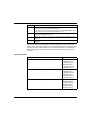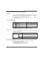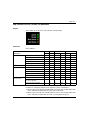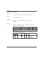
1
Quantum Ethernet I/O
S1A48978 07/2011
Quantum Ethernet I/O
Ethernet Remote I/O Modules
Installation and Configuration Guide
S1A48978.00
07/2011
www.schneider-electric.com
The information provided in this documentation contains general descriptions and/or
technical characteristics of the performance of the products contained herein. This
documentation is not intended as a substitute for and is not to be used for
determining suitability or reliability of these products for specific user applications. It
is the duty of any such user or integrator to perform the appropriate and complete
risk analysis, evaluation and testing of the products with respect to the relevant
specific application or use thereof. Neither Schneider Electric nor any of its affiliates
or subsidiaries shall be responsible or liable for misuse of the information contained
herein. If you have any suggestions for improvements or amendments or have found
errors in this publication, please notify us.
No part of this document may be reproduced in any form or by any means, electronic
or mechanical, including photocopying, without express written permission of
Schneider Electric.
All pertinent state, regional, and local safety regulations must be observed when
installing and using this product. For reasons of safety and to help ensure
compliance with documented system data, only the manufacturer should perform
repairs to components.
When devices are used for applications with technical safety requirements, the
relevant instructions must be followed.
Failure to use Schneider Electric software or approved software with our hardware
products may result in injury, harm, or improper operating results.
Failure to observe this information can result in injury or equipment damage.
© 2011 Schneider Electric. All rights reserved.
2
S1A48978 07/2011
Table of Contents
Safety Information . . . . . . . . . . . . . . . . . . . . . . . . . . . . . .
About the Book . . . . . . . . . . . . . . . . . . . . . . . . . . . . . . . . .
Chapter 1 Characteristics of Ethernet Remote I/O Modules . . . . .
140 CRP 312 00 Module Description . . . . . . . . . . . . . . . . . . . . . . . . . . . .
140 CRA 312 00 Module Description . . . . . . . . . . . . . . . . . . . . . . . . . . . .
Module Specifications . . . . . . . . . . . . . . . . . . . . . . . . . . . . . . . . . . . . . . . .
I/O Devices . . . . . . . . . . . . . . . . . . . . . . . . . . . . . . . . . . . . . . . . . . . . . . . .
Chapter 2 Installation. . . . . . . . . . . . . . . . . . . . . . . . . . . . . . . . . . . . .
2.1 Installing Quantum Ethernet I/O Modules on a Quantum Rack . . . . . . . .
Installing the Quantum Controller . . . . . . . . . . . . . . . . . . . . . . . . . . . . . . .
Mounting a Quantum Ethernet I/O Module on the Backplane. . . . . . . . . .
Quantum Ethernet I/O Module Installation Considerations . . . . . . . . . . . .
Remote I/O Network Cable Installation . . . . . . . . . . . . . . . . . . . . . . . . . . .
2.2 Installing the 140 CRA 312 00 on the Remote Drop . . . . . . . . . . . . . . . . .
Installing the 140 CRA 312 00 Module . . . . . . . . . . . . . . . . . . . . . . . . . . .
Installing Ethernet Remote I/O Drops on a Quantum Rack. . . . . . . . . . . .
Setting the Location of the Ethernet Remote I/O Drop . . . . . . . . . . . . . . .
2.3 Remote I/O Infrastructure Cables . . . . . . . . . . . . . . . . . . . . . . . . . . . . . . .
Cable Installation. . . . . . . . . . . . . . . . . . . . . . . . . . . . . . . . . . . . . . . . . . . .
Duplicate IP Address Checking. . . . . . . . . . . . . . . . . . . . . . . . . . . . . . . . .
Loss of I/O Connection . . . . . . . . . . . . . . . . . . . . . . . . . . . . . . . . . . . . . . .
Chapter 3 Configuration and Programming with Unity Pro . . . . . .
3.1 Creating a Unity Pro Project . . . . . . . . . . . . . . . . . . . . . . . . . . . . . . . . . . .
Configuring the Local Rack . . . . . . . . . . . . . . . . . . . . . . . . . . . . . . . . . . . .
Configuring the Ethernet Remote I/O Drop . . . . . . . . . . . . . . . . . . . . . . . .
Available Unity Pro Configuration Tabs. . . . . . . . . . . . . . . . . . . . . . . . . . .
3.2 Unity Pro Configuration for Remote I/O Ethernet Modules . . . . . . . . . . . .
IP Configuration. . . . . . . . . . . . . . . . . . . . . . . . . . . . . . . . . . . . . . . . . . . . .
RSTP Bridge Configuration . . . . . . . . . . . . . . . . . . . . . . . . . . . . . . . . . . . .
SNMP Agent Configuration . . . . . . . . . . . . . . . . . . . . . . . . . . . . . . . . . . . .
Service Port Configuration . . . . . . . . . . . . . . . . . . . . . . . . . . . . . . . . . . . .
S1A48978 07/2011
7
11
15
16
19
22
24
27
28
29
30
32
33
35
36
37
38
39
40
42
43
45
46
47
49
50
51
52
53
54
56
3
4
3.3 Unity Pro Configuration for Ethernet Remote I/O Drops . . . . . . . . . . . . .
Configuring the Size and Location of Data . . . . . . . . . . . . . . . . . . . . . . .
Configuring the Parameters . . . . . . . . . . . . . . . . . . . . . . . . . . . . . . . . . . .
Device DDT Parameters . . . . . . . . . . . . . . . . . . . . . . . . . . . . . . . . . . . . .
3.4 Derived Data Types . . . . . . . . . . . . . . . . . . . . . . . . . . . . . . . . . . . . . . . . .
Device DDT Names (140 CRP 312 00 Head Module). . . . . . . . . . . . . . .
Device DDT Names (140 CRA 312 00 Drop Module) . . . . . . . . . . . . . . .
3.5 Application Download . . . . . . . . . . . . . . . . . . . . . . . . . . . . . . . . . . . . . . .
Downloading the Application to the PLC . . . . . . . . . . . . . . . . . . . . . . . . .
58
59
60
63
64
65
69
73
73
Chapter 4 Explicit Messaging. . . . . . . . . . . . . . . . . . . . . . . . . . . . . . .
75
4.1 EtherNet/IP Explicit Messaging Using MBP_MSTR . . . . . . . . . . . . . . . .
Supported MBP_MSTR Function Codes . . . . . . . . . . . . . . . . . . . . . . . . .
EtherNet/IP Explicit Messaging Services. . . . . . . . . . . . . . . . . . . . . . . . .
Configuring the CONTROL and DATABUF Parameters . . . . . . . . . . . . .
4.2 Explicit Messaging via the Unity Pro GUI . . . . . . . . . . . . . . . . . . . . . . . .
Sending Explicit Messages to EtherNet/IP Devices. . . . . . . . . . . . . . . . .
4.3 Immediate I/O Access (IU_ERIO) . . . . . . . . . . . . . . . . . . . . . . . . . . . . . .
Description . . . . . . . . . . . . . . . . . . . . . . . . . . . . . . . . . . . . . . . . . . . . . . . .
76
77
78
80
82
82
84
84
Chapter 5 Implicit Messaging. . . . . . . . . . . . . . . . . . . . . . . . . . . . . . .
89
The MAST Task in Implicit Exchanges . . . . . . . . . . . . . . . . . . . . . . . . . .
89
Chapter 6 Diagnostics. . . . . . . . . . . . . . . . . . . . . . . . . . . . . . . . . . . . .
91
6.1 LED Indicators . . . . . . . . . . . . . . . . . . . . . . . . . . . . . . . . . . . . . . . . . . . . .
LED Indicators on the 140 CRP 312 00 Module . . . . . . . . . . . . . . . . . . .
LED Indicators on the 140 CRA 312 00 Module . . . . . . . . . . . . . . . . . . .
6.2 Service Port Management . . . . . . . . . . . . . . . . . . . . . . . . . . . . . . . . . . . .
Service Port Configuration for 140 CRP 312 00 . . . . . . . . . . . . . . . . . . .
Service Port Configuration for 140 CRA 312 00 . . . . . . . . . . . . . . . . . . .
6.3 Diagnostics Available through the CPU . . . . . . . . . . . . . . . . . . . . . . . . . .
System Diagnostics . . . . . . . . . . . . . . . . . . . . . . . . . . . . . . . . . . . . . . . . .
Device Data Types for the Remote I/O Modules . . . . . . . . . . . . . . . . . . .
6.4 Diagnostics through Modbus/TCP . . . . . . . . . . . . . . . . . . . . . . . . . . . . . .
Modbus Diagnostic Codes . . . . . . . . . . . . . . . . . . . . . . . . . . . . . . . . . . . .
6.5 EtherNet/IP CIP Objects . . . . . . . . . . . . . . . . . . . . . . . . . . . . . . . . . . . . .
About CIP Objects . . . . . . . . . . . . . . . . . . . . . . . . . . . . . . . . . . . . . . . . . .
RSTP Diagnostics Object . . . . . . . . . . . . . . . . . . . . . . . . . . . . . . . . . . . .
Service Port Control Object . . . . . . . . . . . . . . . . . . . . . . . . . . . . . . . . . . .
6.6 Diagnostics through Unity Pro . . . . . . . . . . . . . . . . . . . . . . . . . . . . . . . . .
Device Services . . . . . . . . . . . . . . . . . . . . . . . . . . . . . . . . . . . . . . . . . . . .
EtherNet/IP Objects . . . . . . . . . . . . . . . . . . . . . . . . . . . . . . . . . . . . . . . . .
Service Port Management (Online Action). . . . . . . . . . . . . . . . . . . . . . . .
Pinging a Network Device . . . . . . . . . . . . . . . . . . . . . . . . . . . . . . . . . . . .
92
93
95
97
98
99
100
101
103
104
104
106
107
108
112
114
115
116
117
119
S1A48978 07/2011
Chapter 7 Firmware Upgrade . . . . . . . . . . . . . . . . . . . . . . . . . . . . . .
121
140 CRP 312 00 Firmware Upgrade . . . . . . . . . . . . . . . . . . . . . . . . . . . . .
140 CRA 312 00 Firmware Upgrade . . . . . . . . . . . . . . . . . . . . . . . . . . . . .
122
125
Glossary . . . . . . . . . . . . . . . . . . . . . . . . . . . . . . . . . . . . . . . . . . .
Index . . . . . . . . . . . . . . . . . . . . . . . . . . . . . . . . . . . . . . . . . . .
133
155
S1A48978 07/2011
5
6
S1A48978 07/2011
Safety Information
§
Important Information
NOTICE
Read these instructions carefully, and look at the equipment to become familiar with
the device before trying to install, operate, or maintain it. The following special
messages may appear throughout this documentation or on the equipment to warn
of potential hazards or to call attention to information that clarifies or simplifies a
procedure.
S1A48978 07/2011
7
PLEASE NOTE
Electrical equipment should be installed, operated, serviced, and maintained only by
qualified personnel. No responsibility is assumed by Schneider Electric for any
consequences arising out of the use of this material.
A qualified person is one who has skills and knowledge related to the construction
and operation of electrical equipment and its installation, and has received safety
training to recognize and avoid the hazards involved.
BEFORE YOU BEGIN
Do not use this product on machinery lacking effective point-of-operation guarding.
Lack of effective point-of-operation guarding on a machine can result in serious
injury to the operator of that machine.
WARNING
UNGUARDED MACHINERY CAN CAUSE SERIOUS INJURY
z
z
Do not use this software and related automation equipment on equipment which
does not have point-of-operation protection.
Do not reach into machinery during operation.
Failure to follow these instructions can result in death, serious injury, or
equipment damage.
This automation equipment and related software is used to control a variety of
industrial processes. The type or model of automation equipment suitable for each
application will vary depending on factors such as the control function required,
degree of protection required, production methods, unusual conditions, government
regulations, etc. In some applications, more than one processor may be required, as
when backup redundancy is needed.
8
S1A48978 07/2011
Only the user can be aware of all the conditions and factors present during setup,
operation, and maintenance of the machine; therefore, only the user can determine
the automation equipment and the related safeties and interlocks which can be
properly used. When selecting automation and control equipment and related
software for a particular application, the user should refer to the applicable local and
national standards and regulations. The National Safety Council’s Accident
Prevention Manual (nationally recognized in the United States of America) also
provides much useful information.
In some applications, such as packaging machinery, additional operator protection
such as point-of-operation guarding must be provided. This is necessary if the
operator’s hands and other parts of the body are free to enter the pinch points or
other hazardous areas and serious injury can occur. Software products alone
cannot protect an operator from injury. For this reason the software cannot be
substituted for or take the place of point-of-operation protection.
Ensure that appropriate safeties and mechanical/electrical interlocks related to
point-of-operation protection have been installed and are operational before placing
the equipment into service. All interlocks and safeties related to point-of-operation
protection must be coordinated with the related automation equipment and software
programming.
NOTE: Coordination of safeties and mechanical/electrical interlocks for point-ofoperation protection is outside the scope of the Function Block Library, System User
Guide, or other implementation referenced in this documentation.
START-UP AND TEST
Before using electrical control and automation equipment for regular operation after
installation, the system should be given a start-up test by qualified personnel to
verify correct operation of the equipment. It is important that arrangements for such
a check be made and that enough time is allowed to perform complete and
satisfactory testing.
CAUTION
EQUIPMENT OPERATION HAZARD
z
z
z
Verify that all installation and set up procedures have been completed.
Before operational tests are performed, remove all blocks or other temporary
holding means used for shipment from all component devices.
Remove tools, meters, and debris from equipment.
Failure to follow these instructions can result in injury or equipment damage.
Follow all start-up tests recommended in the equipment documentation. Store all
equipment documentation for future references.
Software testing must be done in both simulated and real environments.
S1A48978 07/2011
9
Verify that the completed system is free from all short circuits and grounds, except
those grounds installed according to local regulations (according to the National
Electrical Code in the U.S.A, for instance). If high-potential voltage testing is
necessary, follow recommendations in equipment documentation to prevent
accidental equipment damage.
Before energizing equipment:
z Remove tools, meters, and debris from equipment.
z Close the equipment enclosure door.
z Remove ground from incoming power lines.
z Perform all start-up tests recommended by the manufacturer.
OPERATION AND ADJUSTMENTS
The following precautions are from the NEMA Standards Publication ICS 7.1-1995
(English version prevails):
z Regardless of the care exercised in the design and manufacture of equipment or
in the selection and ratings of components, there are hazards that can be
encountered if such equipment is improperly operated.
z It is sometimes possible to misadjust the equipment and thus produce
unsatisfactory or unsafe operation. Always use the manufacturer’s instructions as
a guide for functional adjustments. Personnel who have access to these
adjustments should be familiar with the equipment manufacturer’s instructions
and the machinery used with the electrical equipment.
z Only those operational adjustments actually required by the operator should be
accessible to the operator. Access to other controls should be restricted to
prevent unauthorized changes in operating characteristics.
10
S1A48978 07/2011
About the Book
At a Glance
Document Scope
PlantStruxure is a Schneider Electric program specifically designed to address the
key challenges of many different types of users — including plant managers,
operations managers, engineers, maintenance teams, and operators — by
delivering a system that is scalable, flexible, integrated, and collaborative.
This document presents one of the PlantStruxure features — using Ethernet as the
backbone around the Quantum PLC offer and connecting a Quantum local rack to
remote I/O drops. This feature is known as Quantum Ethernet I/O or Quantum EIO.
This guide describes these modules and their roles in a Quantum EIO system:
z 140 CRP 312 00: head module on the local rack in a remote I/O main ring
z 140 CRA 312 00: adapter module in the remote I/O drop
NOTE: The specific configuration settings contained in this guide are for
instructional purposes only. The settings required for your specific application may
differ from the examples presented in this guide.
Validity Note
This document is valid for Unity Pro 6.0 or later.
The technical characteristics of the device(s) described in this manual also appear
online. To access this information online:
Step
S1A48978 07/2011
Action
1
Go to the Schneider Electric home page www.schneider-electric.com.
2
In the Search box type the model number of a product or the name of a product
range.
z Do not include blank spaces in the model number/product range.
z To get information on a grouping similar modules, use asterisks (*).
11
Step
Action
3
If you entered a model number, go to the Product datasheets search results
and click on the model number that interests you.
If you entered the name of a product range, go to the Product Ranges search
results and click on the product range that interests you.
4
If more than one model number appears in the Products search results, click on
the model number that interests you.
5
Depending on the size of your screen, you may need to scroll down to see the
data sheet.
6
To save or print a data sheet as a .pdf file, click Download XXX product
datasheet.
The characteristics presented in this manual should be the same as those that
appear online. In line with our policy of constant improvement we may revise content
over time to improve clarity and accuracy. In the event that you see a difference
between the manual and online information, use the online information as your
reference.
Related Documents
Title of Documentation
Reference Number
Quantum Ethernet I/O System Planning Guide
S1A48959 (English),
S1A48961 (French),
S1A48962 (German),
S1A48964 (Italian),
S1A48965 (Spanish),
S1A48966 (Chinese)
Modicon Quantum Change Configuration on the Fly User Guide S1A48967 (English),
S1A48968 (French),
S1A48969 (German),
S1A48970 (Italian),
S1A48972 (Spanish),
S1A48976 (Chinese)
Modicon Quantum Hot Standby System User Manual
12
35010533 (English),
35010534 (French),
35010535 (German),
35013993 (Italian),
35010536 (Spanish),
35012188 (Chinese).
S1A48978 07/2011
Unity Pro Program Languages and Structure Reference Manual 35006144 (English),
35006145 (French),
35006146 (German),
35006147 (Spanish),
35013361 (Italian),
35013362 (Chinese)
Unity Pro Operating Modes
33003101 (English),
33003102 (French),
33003103 (German),
33003104 (Spanish),
33003696 (Italian),
33003697 (Chinese)
Quantum with Unity Pro Hardware Reference Manual
35010529 (English),
35010530 (French),
35010531 (German),
35010532 (Spanish),
35013975 (Italian),
35012184 (Chinese)
Unity Pro Installation Manual
35014792 (French),
35014793 (English),
35014794 (German),
35014795 (Spanish),
35014796 (Italian),
35012191 (Chinese)
You can download these technical publications and other technical information from
our website at www.schneider-electric.com.
User Comments
We welcome your comments about this document. You can reach us by e-mail at
[email protected].
S1A48978 07/2011
13
14
S1A48978 07/2011
Quantum Ethernet I/O
Characteristics of Ethernet Remote I/O Modules
S1A48978 07/2011
Characteristics of Ethernet
Remote I/O Modules
1
Introduction
This chapter describes the head and adapter modules for Ethernet remote I/O
communications in a Quantum EIO system. Specifically, those modules are:
z 140 CRP 312 00: head module on a local Quantum rack
z 140 CRA 312 00: adapter module on an Ethernet remote I/O rack
This chapter includes physical characteristics, port descriptions, and agency
specifications for these modules.
What’s in this Chapter?
This chapter contains the following topics:
Topic
140 CRP 312 00 Module Description
S1A48978 07/2011
Page
16
140 CRA 312 00 Module Description
19
Module Specifications
22
I/O Devices
24
15
Characteristics of Ethernet Remote I/O Modules
140 CRP 312 00 Module Description
Introduction
The 140 CRP 312 00 Quantum module is the head module on the main rack of
Quantum Ethernet I/O installations. This module allows the PLC to connect to an
Ethernet network and control remote I/O devices.
Functionality
The main purpose of the 140 CRP 312 00 module is to provide I/O scanning
services of remote I/O devices on either a remote I/O network or a device network,
which contains remote I/O and distributed I/O devices. The module is directly
connected to the remote I/O network main ring, and it manages the remote I/O
network through a daisy chain loop topology. This module also provides various
Ethernet services, such as configuration for remote I/O devices and diagnostics.
You can use these function blocks with the 140 CRP 312 00 module:
IU_ERIO
z DROP
z XDROP
z
Only one 140 CRP 312 00 module can be configured on the local rack. This module
has interfaces for communicating with Ethernet remote I/O devices on the network.
The 140 CRP 312 00 module allows the PLC to connect to an Ethernet network and
to have a deterministic I/O exchange with modules in the Ethernet remote I/O drops.
The 140 CRP 312 00 module is dedicated to the management of remote I/O devices
only. Other services of the 140 CRP 312 00 module:
z The module uses RSTP to enable all remote I/O devices on the main ring to
recover from a communication disruption within 50 ms.
z The module can configure IP parameters and the configurations for I/O modules
on the drops for up to 31 remote I/O devices.
z The module provides a communication path (through an interlink) to allow
distributed I/O and control network traffic to participate on the remote I/O network.
z The module supports Hot Standby functionality. The primary 140 CRP 312 00
module and the standby 140 CRP 312 00 module do not swap their IP addresses
when a switchover occurs.
16
S1A48978 07/2011
Characteristics of Ethernet Remote I/O Modules
External Features
140 CRP 312 00:
1
2
3
4
5
S1A48978 07/2011
LED display
SERVICE port (ETH 1)
INTERLINK port (ETH 2)
DEVICE NETWORK port (ETH 3)
DEVICE NETWORK port (ETH 4)
17
Characteristics of Ethernet Remote I/O Modules
External Ports
The 140 CRP 312 00 module monitors the functionality of network links depending
on which links are connected to the network. The module has 4 external ports (but
only 1 IP address):
Port
Quantity Description
SERVICE
1
The SERVICE port allows the diagnosis of Ethernet ports and
provides access to external tools and devices (Unity Pro,
ConneXview, HMI, etc.). The port supports these modes:
z access port (default): This mode supports Ethernet
communications.
z port mirroring: In this mode, data traffic from one or more of the
other 3 ports is copied to this port. This allows a connected tool
to monitor and analyze the port traffic.
z disabled
NOTE:
z Do not connect a device with a speed in excess of 100 Mbps to
the SERVICE port. If the device is configured for a speed that
exceeds 100 Mbps, the Ethernet link may not be established
between the device and the module through the SERVICE port.
z You can configure the SERVICE port either on line or off line.
z In port mirroring mode, the SERVICE port acts like a read-only
port. That is, you cannot access devices (ping, connection to
Unity Pro, etc.) through the SERVICE port.
Refer to Service Port Configuration (see page 56).
18
INTERLINK 1
The INTERLINK port provides connectivity to other Quantum EIO
modules.
DEVICE
2
NETWORK
These 2 copper ports provide:
z connections for remote I/O communications
z cable redundancy via the daisy chain loop architecture
S1A48978 07/2011
Characteristics of Ethernet Remote I/O Modules
140 CRA 312 00 Module Description
Introduction
A 140 CRA 312 00 module is the adapter module located in any Quantum Ethernet
I/O installation. A remote I/O drop can be connected directly to the main ring cable
or to a sub-ring cable.
Functionality
The 140 CRA 312 00 Quantum module exchanges data with the remote I/O head
module 140 CRP 312 00.
Features:
z The input data from the Ethernet remote I/O drop is collected and published to
the remote I/O scanner.
z The output modules are updated with the data received from the remote I/O
scanner.
z The protocol used for exchange is EtherNet/IP.
z The remote I/O scanner views the 140 CRA 312 00 module as a remote I/O
adapter.
z The exchanges are deterministic, which means that the time it takes to resolve a
remote I/O logic scan is predictable.
The 140 CRA 312 00 module has 3 external Ethernet ports and, therefore, 3 MAC
addresses (but only 1 IP address). Two of the Ethernet ports allow implicit I/O
exchanges with a remote I/O scanner adapter. (An implicit I/O exchange has a
maximum frame size of 1400 bytes.) The ports can be implemented alone or in
redundant mode.
You can use a maximum of 31 adapter modules (140 CRA 312 00) in a single
Ethernet remote I/O network. For network topology planning, refer to the
PlantStruxure Quantum Ethernet I/O System Planning Guide for more details of
these topologies.
S1A48978 07/2011
19
Characteristics of Ethernet Remote I/O Modules
External Features
140 CRA 312 00:
1
2
3
4
5
20
LED display
rotary switches
SERVICE port (ETH 1)
DEVICE NETWORK port (ETH 2)
DEVICE NETWORK port (ETH 3)
S1A48978 07/2011
Characteristics of Ethernet Remote I/O Modules
External Ports
This module has three 10/100 Base-T Ethernet ports:
Port
Description
SERVICE
The SERVICE port allows the diagnosis of Ethernet ports and provides
access to external tools and devices (Unity Pro, ConneXview, HMI, etc.). The
port supports these modes:
z access port (default): This mode supports Ethernet communications.
z port mirroring: In this mode, data traffic from one of the other 3 ports is
copied to this port. This allows a connected management tool to monitor
and analyze the port traffic.
z disabled
NOTE:
z Do not connect a device with a speed in excess of 100 Mbps to the
SERVICE port. If the device is configured for a speed that exceeds
100 Mbps, the Ethernet link may not be established between the device
and the module through the SERVICE port.
z You can configure the SERVICE port either on line or off line.
z In port mirroring mode, the SERVICE port acts like a read-only port. That
is, you cannot access devices (ping, connection to Unity Pro, etc.) through
the SERVICE port.
Refer to Service Port Configuration (see page 56).
DEVICE
NETWORK
The 2 DEVICE NETWORK copper ports provide:
z connections for remote I/O communications
z cable redundancy
Cable Redundancy
Use a daisy chain network configuration that implements the RSTP service to
establish redundant communications between the 140 CRA 312 00 module and a
remote I/O scanner. The module operates normally when at least one of the 2
physical paths to the 140 CRP 312 00 is valid. (Refer to the PlantStruxure Quantum
Ethernet I/O System Planning Guide for more details of these topologies.)
S1A48978 07/2011
21
Characteristics of Ethernet Remote I/O Modules
Module Specifications
Product Certification
The Quantum remote I/O modules for Quantum EIO meet these standards:
UL (UL508)
CSA (CSA22.2 no. 142)
C-tick
Hazardous locations (Cl1 div 2)
IEC61000-4-16
EMI EN 55011
CE
EN 61131-1
IEC 61131-2 (zone B and zone C, except surges on AC: zone B only)
Quantum EIO modules conform to these product certification and marine classification authorities:
Key
Certification Body
Country
ABS
American Bureau of Shipping
United States
BV
Bureau Veritas
France
DNV
Det Norske Veritas
Norway
GOST
Gosudarstvennyy Standart
Russia
GL
Germanischer Lloyd
Germany
LR
Lloyd’s Register
United Kingdom
RINA
Registro Italiano Navale
Italy
The electrical isolation within Quantum EIO system modules complies with the
1500 Vac/2250 Vdc 60s from IEEE 802.3 2008.
Environmental Requirements
Parameter
Reference
Specification
protection
EN 61131-2
IP20
protection class
EN 61131-2
IEC 60527
over voltage class EN 61131-2
22
protection class 1
category II
S1A48978 07/2011
Characteristics of Ethernet Remote I/O Modules
Parameter
Reference
Specification
operating
temperature
IEC 60068-2-1
0 ... 60° C
Ab&Ad (cold)
IEC 60068-2-2
Bb&Bd (cold)
storage
temperature
IEC 60068-2-1
-40 ... 85° C
Ab&Ad (cold)
IEC 60068-2-2
Bb&Bd (cold)
sinusoidal
vibration
operating shock
altitude
free fall, random
(packaged)
IEC 60068-2-6fC
EN 61131-2
IEC 60068-2-27Ea
z .5 ... 8.4 Hz at 3.5 mm constant amplitude
z 8.4 ... 150 Hz at 1g constant acceleration
z 10 cycles at sweep rate of 1 oct/min
30 g peak, 11 ms, half-sine wave, 3 shocks in
each direction (+ and -) for each of the 3 principle
axes
(operating)
2000 m
(transport)
3000 m
EN 61131-2
5 random drops from 1 m onto flat surfaces
IEC 60068-2-32
test ed., method 1
free fall, flat drop
(unpackaged)
EN 61131-2
IEC 60068-2-32
z 2 random drops from 1 m onto flat surfaces
z 5 drops from 0.1 m onto flat surfaces
test ed., method 1
S1A48978 07/2011
free fall, angled
(unpackaged)
EN 61131-2
5 drops from 0.1 m onto each corner
relative humidity
(operating)
IEC 60068-2-78Ca
93% (+/- 2%, noncondensing) at 60° C
relative humidity
(nonoperating)
IEC 60068
93% (+/- 2%, noncondensing) at 60° C
IEC 60068-2-31
23
Characteristics of Ethernet Remote I/O Modules
I/O Devices
Introduction
This topic lists the I/O devices that can be connected to an Ethernet remote I/O
network.
Analog and Digital Modules
These analog and digital I/O modules are supported in remote I/O drops:
Input
Output
Input/Output
140 ACI 030 00
140 ACO 020 00
140 AMM 090 00
140 ACI 040 00
140 ACO 130 00
140 AII 330 00
140 AIO 330 00
140 AII 330 10
140 AVO 020 00
Analog I/O Modules:
140 ARI 030 10
140 ATI 030 00
140 AVI 030 00
24
S1A48978 07/2011
Characteristics of Ethernet Remote I/O Modules
Input
Output
Input/Output
140 DDO 153 10
140 DDM 390 00
Digital I/O Modules:
140 DDI 153 10
140 DDI 353 00
140 DDO 353 00
140 DDM 690 00
140 DDI 353 10
140 DDO 353 01
140 DAM 590 00
140 DDI 364 00
140 DDO 353 10
140 DDI 673 00
140 DDO 364 00
140 DDI 841 00
140 DDO 843 00
140 DDI 853 00
140 DDO 885 00
140 DAI 340 00
140 DAO 840 00
140 DAI 353 00
140 DAO 840 10
140 DAI 440 00
140 DAO 842 10
140 DAI 453 00
140 DAO 842 20
140 DAI 540 00
140 DAO 853 00
140 DAI 543 00
140 DRA 840 00
140 DAI 553 00
140 DRC 830 00
140 DAI 740 00
140 DVO 853 00
140 DAI 753 00
140 DIO 330 00
140 DII 330 00
140 DSI 353 00
Intelligent and Special Purpose Modules
These intelligent/special purpose modules are supported in remote I/O drops:
Type
Module
expert
140 ERT 854 10
140 ESI 062 10
counting
140 EHC 105 00
140 EHC 202 00
communication
S1A48978 07/2011
140 XBE 100 00
25
Characteristics of Ethernet Remote I/O Modules
26
S1A48978 07/2011
Quantum Ethernet I/O
Installation
S1A48978 07/2011
Installation
2
Overview
This chapter describes the hardware installation of a Quantum EIO system. It
includes the installation of modules in the local rack and the Ethernet remote I/O
drop to which it is connected. Other discussions include the interconnections
between rack-mounted modules and the hardware considerations for different PLC
platforms.
What’s in this Chapter?
This chapter contains the following sections:
Section
S1A48978 07/2011
Topic
Page
2.1
Installing Quantum Ethernet I/O Modules on a Quantum Rack
28
2.2
Installing the 140 CRA 312 00 on the Remote Drop
35
2.3
Remote I/O Infrastructure Cables
39
27
Installation
2.1
Installing Quantum Ethernet I/O Modules on a
Quantum Rack
Introduction
This section describes the installation of these Quantum Ethernet I/O modules:
140 CRP 312 00 head module (on the main rack)
z 140 CRA 312 00 adapter (on the remote drop)
z
What’s in this Section?
This section contains the following topics:
Topic
Installing the Quantum Controller
28
Page
29
Mounting a Quantum Ethernet I/O Module on the Backplane
30
Quantum Ethernet I/O Module Installation Considerations
32
Remote I/O Network Cable Installation
33
S1A48978 07/2011
Installation
Installing the Quantum Controller
Introduction
For any Quantum Ethernet I/O system, install a Quantum controller on the main
rack. Only processors with firmware version 3.0 or higher are compatible with
Quantum Ethernet I/O installations.
Compatible Processors
Compatible processors:
Processor Type
Part
standalone
140 CPU 651 50
140 CPU 651 60
140 CPU 652 60
Hot Standby
40 CPU 671 60
140 CPU 672 61
NOTE: Low-end Quantum processors (140 CPU 434 12U, 140 CPU 534 14U,
140 CPU 311 10) and Quantum safety processors (140 CPU 651 60S,
140 CPU 671 60S) are not compatible with Quantum Ethernet I/O systems.
Selecting a Power Supply
When installing a Quantum controller, add a power supply module that is capable of
supplying power to all modules on the rack.
S1A48978 07/2011
29
Installation
Mounting a Quantum Ethernet I/O Module on the Backplane
Introduction
Use these steps to installation these Quantum Ethernet I/O modules on the
Quantum rack:
z 140 CRP 312 00 head module (on the main rack)
z 140 CRA 312 00 adapter (on the remote drop)
Considerations
Do not apply power to a Quantum rack until connections are made at both ends of
the Ethernet cable. For example, connect the cable to both the 140 CRP 312 00 and
another device (140 CRA 312 00 or DRS) before you turn on the power.
DANGER
ELECTRICAL SHOCK HAZARD
z
z
Switch off the power supply to the automation controller stations at both ends of
the connection before inserting or removing an Ethernet cable.
Use suitable insulation equipment when inserting or removing all or part of this
equipment.
Failure to follow these instructions will result in death or serious injury.
Use fiber-optic cable to establish a communications link when it is not possible to
master potential between distant grounds.
30
S1A48978 07/2011
Installation
Mounting a Module
Step
Action
1
Hold the module at an angle and mount it on the 2 hooks near the top of the
backplane. The figure shows the correct way to hold the module:
2
Swing the module down so the connector engages the backplane connector.
3
Use a Phillips-head screw driver to tighten the screw at the bottom of the module
from 2 to 4 in-lbs or from .22 through .45 N•m of torque.
Replacing a Module
You can replace a Quantum Ethernet I/O module at any time using another module
with compatible firmware. The replacement module obtains its operating parameters
over the backplane connection from the CPU. The transfer occurs immediately at
the next cycle to the device.
The operating parameters that the CPU sends to a replacement module do not
include any parameter values that were edited in the original module using explicit
messaging SET commands.
S1A48978 07/2011
31
Installation
Quantum Ethernet I/O Module Installation Considerations
Introduction
Observe the guidelines below when you install these Quantum Ethernet I/O
modules:
z 140 CRP 312 00 head module (on the main rack)
z 140 CRA 312 00 adapter (on the remote drop)
Grounding Considerations
DANGER
ELECTRICAL SHOCK HAZARD
z
z
Switch off the power supply to the automation controller stations at both ends of
the connection before inserting or removing an Ethernet cable.
Use suitable insulation equipment when inserting or removing all or part of this
equipment.
Failure to follow these instructions will result in death or serious injury.
Use fiber-optic cable to establish a communications link when it is not possible to
master potential between distant grounds.
NOTE: Refer to the ground connections information in the Grounding and
Electromagnetic Compatibility of PLC Systems User Manual.
Installation
You can apply power to the Quantum Ethernet I/O controller rack after the
140 CRP 312 00 or 140 CRA 312 00 module is inserted:
z Successful installation:
z Intialization is finished.
z Interconnections to other modules are validated (140 CRP 312 00 only).
z
Unsuccessful installation:
z Initialization does not finish.
z Interconnections to other modules are not validated (140 CRP 312 00 only).
You can see the status of the installation on the LED display (see page 93).
NOTE: These guidelines pertain to the installation of a single 140 CRP 312 00 or
140 CRA 312 00 module, not the entire network. For network power-up guidelines,
refer to the PlantStruxure Quantum Ethernet I/O System Planning Guide.
32
S1A48978 07/2011
Installation
Remote I/O Network Cable Installation
Introduction
Your application can include:
z communications with a simple remote I/O daisy chain loop
z communications with a mix of remote I/O and distributed I/O networks
The cable connections to the 140 CRP 312 00 module on the local rack are different
in these scenarios. They are discussed below.
Each Device Network port on the 140 CRP 312 00 head module is connected to the
main ring of the daisy chain. Likewise, each Device Network port on a
140 CRA 312 00 adapter module is connected to a Quantum Ethernet I/O device.
The 140 CRP 312 00 head module and the 140 CRA 312 00 adapter module do not
have fiber-optic ports.
The Ethernet ports are clearly labeled (see page 15) on the 140 CRP 312 00 head
module and the 140 CRA 312 00 adapter module.
Simple Remote I/O Daisy Chain Loop
The 140 CRP 312 00 supports communications with Ethernet remote I/O drops in
daisy chain loops:
1
2
140 CRP 312 00 head module on the local rack
140 CRA 312 00 adapter module on a remote I/O drop
When you support only remote I/O, you do not have to link the 140 CRP 312 00
module to other communication modules on the local rack.
S1A48978 07/2011
33
Installation
Mix of Remote I/O Drops, Distributed I/O Devices, and Clouds
The Quantum Ethernet I/O architecture allows distributed I/O devices to participate
directly on the remote I/O network. This can be useful if, for example, you want to
integrate a SCADA or HMI panel or some other kind of non-Quantum device into the
remote I/O network.
Distributed I/O devices cannot be connected directly to the main ring of the remote
I/O network, but they can be connected via a DRS. Most DRS preconfigurations
enable some switch ports to support distributed I/O clouds:
1
2
3
4
5
main ring
140 CRP 312 00 interlinked to 140 NOE 771 •• module on the local rack
DRS
DRS connection to distributed I/O sub-ring
DRS connection to distributed I/O cloud
Some DRS preconfigurations support the connection of distributed I/O devices
connected directly to a sub-ring. In these configurations, the distributed I/O devices
have the advantage of cable redundancy provided by the sub-ring loop. In order for
a distributed I/O device to operate on a sub-ring, it must have two Ethernet ports and
support RSTP.
The above figure shows 2 STB islands used as distributed I/O devices on a sub-ring.
The network interface module installed in each island is an STB NIP 2311 NIM,
which has dual Ethernet ports and the RSTP service.
34
S1A48978 07/2011
Installation
2.2
Installing the 140 CRA 312 00 on the Remote Drop
Introduction
This section describes the installation of the Quantum 140 CRA 312 00 module in
an Ethernet remote I/O drop.
What’s in this Section?
This section contains the following topics:
Topic
S1A48978 07/2011
Page
Installing the 140 CRA 312 00 Module
36
Installing Ethernet Remote I/O Drops on a Quantum Rack
37
Setting the Location of the Ethernet Remote I/O Drop
38
35
Installation
Installing the 140 CRA 312 00 Module
Locate a Backplane Slot
The 140 CRA 312 00 adapter module can be inserted in any slot in the remote I/O
drop. Refer to the directions for installing a Quantum module on the backplane
(see page 30).
Power Consumption
Power consumption is 1.2 A on 3.3 Vdc power rail of the backplane (4 W). The
140 CRA 312 00 module supports Quantum modules on 1 or 2 racks. Each rack
supports 16 slots. (Power consumption has no relation to the number of installed
rack modules.)
Select a Power Supply
When configuring the PLC station, use a power supply module that is capable of
supplying power to all rack modules.
Install a Quantum power supply module in to any slot on the Quantum rack. The
selected power module should be suited to your unique system requirements. These
modules (and their conformally coated versions) are supported:
Power Supply Type
standalone
Part
140 CPS 211 00 (C)
140 CPS 511 00 (C)
140 CPS 111 00 (C)
summable
140 CPS 214 00 (C)
140 CPS 414 00 (C)
140 CPS 114 20 (C)
redundant
140 CPS 224 00 (C)
140 CPS 424 00 (C)
140 CPS 524 00 (C)
140 CPS 124 20 (C)
36
S1A48978 07/2011
Installation
Installing Ethernet Remote I/O Drops on a Quantum Rack
Introduction
Use these guidelines to install Ethernet remote I/O drops on Quantum racks.
Racks and Extensions
An Ethernet remote I/O drop can include 1 or 2 racks. In a 2-rack drop, the racks are
linked with the Quantum 140 XBE 100 00 bus extender module and the associated
140 XCA 717 0• cables (1 to 3 m).
Maximum configuration:
Module
Quantity
140 CRA 312 00 rack module
1
power supply module
2*
bus extension modules
2
I/O modules
27
*A separate power supply is required for each rack.
Elsewhere in this guide is a list of modules that remote I/O installations support
(see page 24).
S1A48978 07/2011
37
Installation
Setting the Location of the Ethernet Remote I/O Drop
Setting Rotary Switches
Set the location of the Ethernet remote I/O drop on the network with the rotary
switches on the front of the 140 CRA 312 00 module before you apply power to the
module and before you download the application:
The values you set are applied during a power cycle. If you change the setting of the
rotary switches after the module has powered up, the Mod Status LED
(see page 93) is activated, and a mismatch message is logged in the module
diagnostic.
Because new values on the rotary switches are implemented only at the next power
cycle, we recommend that you set the value before starting the module. (Valid
values: 00 ... 159)
The values on the rotary switches combine with the device prefix (for example,
140CRA_) to create the device name (see page 60). The above figure shows the
Tens switch set to 0 and the Ones switch set to 01, for a device name of
140CRA_001.
NOTE:
The rotary switches can be manipulated with a small flat-tipped screwdriver.
z No software is required to configure or enable the rotary switches.
z Do not use the Stored and Clear IP settings on the Ones rotary switch. (The
functionality of these settings does not apply to remote I/O installations.)
z
38
S1A48978 07/2011
Installation
2.3
Remote I/O Infrastructure Cables
What’s in this Section?
This section contains the following topics:
Topic
S1A48978 07/2011
Page
Cable Installation
40
Duplicate IP Address Checking
42
Loss of I/O Connection
43
39
Installation
Cable Installation
Introduction
Observe these guidelines when making cable connections between remote I/O
devices on a Quantum Ethernet I/O installation. (Remote I/O devices include local
racks, remote I/O drops, or DRSs.)
The distance between 2 consecutive remote I/O devices that are connected by
copper cables cannot exceed 100 m. The distance between 2 consecutive remote
I/O devices that are connected by fiber cables cannot exceed 15 km.
Connections Between Devices
This figure shows the distances between remote I/O devices in Quantum Ethernet
I/O installations:
1
2
3
main rack: This rack includes a 140 CRP 312 00 head module that supports remote I/O
communications.
DRS (with copper ports): This DRS serves to extend the distance between other devices.
DRS (with copper and fiber ports): This DRS extends the distance between devices (up to
15 km).
NOTE: We recommend the use of shielded twisted pair CAT5e (10/100 Mbps)
cables, ideally ConneXium 490NTC000••(U).
40
S1A48978 07/2011
Installation
Interlink
To support distributed I/O sub-rings in Quantum Ethernet I/O installations, establish
an interlink between an Ethernet communication module on the main rack and the
140 CRP 312 00 head module:
1
2
3
main rack: This rack includes a 140 NOE 771 00 communication module that is interlinked
to a 140 CRP 312 00 head module.
DRS: This switch is connected to the main ring and a distributed I/O sub-ring.
distributed I/O sub-ring
You can use the 140 NOE 771 •• communication module instead of the
140 NOE 771 00.
NOTE: For the Interlink connection, we recommend the use of shielded twisted pair
CAT5e (10/100 Mbps) cables. If you add a second Ethernet communication module
(140 NOC 771 •• or 140 NOE 771 ••) to your local rack, you can connect it to a
Control network through a CAT6 (10/100/1000 Mbps) cable.
S1A48978 07/2011
41
Installation
Duplicate IP Address Checking
Introduction
The 140 CRP 312 00 head module on the local rack has 4 ports. The
140 CRA 312 00 adapter module on the remote drop has 3 ports. However, each
module has a single IP address. Therefore, the address conflict detection algorithm
(also called duplicate IP checking) is performed based on the status (link up, link
down) of the ports.
Link Down
These conditions apply when links are lost:
Link Status
Description
A transition has occurred
from 1 connected link to
all links down.
When no module ports are connected to a cable (all links are
down), all services are reset. For example, I/O connections,
Modbus connections, and explicit EtherNet/IP connections
close, but low-level network services (RSTP, switch, etc.) are not
affected. The updated Net Status LED indicates the status.
There is 1 link down and
at least 1 connected link.
There is no impact on services that are running in the module.
Link Up
These conditions apply when links are added:
Link Status
Description
A transition has occurred A duplicate IP check is performed:
from no connected links to z no duplicate: All services start.
1 connected link.
z duplicate: I/O services stop. The 140 CRA 312 00 gets new
configuration and re-downloads the IP configuration. The
system goes to default IP and I/O modules are set to fallback
mode.
A transition has occurred
from at least 1 connected
link to an additional
connected link.
42
A duplicate IP check is performed:
z no duplicated: All services continue.
z duplicate: All services stop.
NOTE: The updated Net Status LED indicates the status.
S1A48978 07/2011
Installation
Loss of I/O Connection
Conditions
An I/O connection can be lost under some conditions:
Condition
CPU
140 CRP 312 00
140 CRA 312 00
z Perform a Hot Swap.
z Replace a module of the same
X
X
X
X
X
type.
There is no remote I/O cable
connection.
The I/O connection is closed.*
X
*Hot Swap of the CPU results in an explicit close (lost I/O connection).
140 CRA 312 00 Fallback
In some instances, the 140 CRA 312 00 adapter module on the remote I/O drop can
lose I/O connections for a period longer than the configured hold up time. During the
hold up, the 140 CRA 312 00 tries to get IP and configuration parameters from the
140 CRP 312 00. When the 140 CRA 312 00 cannot get those parameters:
z inputs: retain last known values
z outputs: set to fallback
NOTE: Configure the hold up time on the Unity Pro Parameter tab (see page 60).
S1A48978 07/2011
43
Installation
44
S1A48978 07/2011
Quantum Ethernet I/O
Configuration and Programming with Unity Pro
S1A48978 07/2011
Configuration and Programming
with Unity Pro
3
Introduction
Use Unity Pro to configure your local rack and remote drops for Ethernet
communications.
What’s in this Chapter?
This chapter contains the following sections:
Section
S1A48978 07/2011
Topic
Page
3.1
Creating a Unity Pro Project
3.2
Unity Pro Configuration for Remote I/O Ethernet Modules
51
3.3
Unity Pro Configuration for Ethernet Remote I/O Drops
58
3.4
Derived Data Types
64
3.5
Application Download
73
46
45
Configuration and Programming with Unity Pro
3.1
Creating a Unity Pro Project
Introduction
Use the instructions in this section to create a Unity Pro project that allows
communications between a local rack and an Ethernet remote I/O drop. Here are the
basic stages of the Unity Pro configuration:
1 Select an high-end Quantum processor to create a new Unity Pro configuration.
2 Add a power supply to the local rack.
3 Add an Ethernet remote I/O head module (140 CRP 312 00) to the local rack.
4 Configure a rack assembly for the Ethernet remote I/O drop.
NOTE: These instructions assume that you have a working knowledge of Unity Pro.
What’s in this Section?
This section contains the following topics:
Topic
46
Page
Configuring the Local Rack
47
Configuring the Ethernet Remote I/O Drop
49
Available Unity Pro Configuration Tabs
50
S1A48978 07/2011
Configuration and Programming with Unity Pro
Configuring the Local Rack
Instructions
Use Unity Pro to install a 140 CRP 312 00 module as the head of a local rack:
Step
Action
Comment
1
In Unity Pro, create a new project.
Path: File → New. (The New Project window appears.)
2
Add a PLC from the New Project
window.
For this example, double-click the 140 CPU 651 50: New Project →
Quantum → 140 CPU 651 50. (The Project Browser appears.)
3
In the Project Browser, doubleclick Local Bus.
Path: Tools → Project Browser → Configuration → Local Bus.
The Local Bus window opens and the rack includes the processor
you selected.
4
Add a power supply to the rack.
For this example, drag the 140 CPS 114 •0 to slot 1 in the local rack:
Tools → Hardware catalog → Local Quantum Drop → Supply →
140 CPS 114 •0
5
Add a 140 CRP 312 00 module to
an available slot in the local rack.
For this example, drag a 140 CRP 312 00 module to slot 4: Tools →
Hardware catalog → Local Quantum Drop → Communication →
140 CRP 312 00
6
In the same manner, drag a
140 NOE module to the local rack.
When you connect distributed I/O devices (through dual-ring
switches) to the Ethernet remote I/O main ring, insert a 140 NOE
communications module on the local rack.
7
Double-click on any empty slot to
add modules to the Local Bus.
For this example, this step is optional.
8
Save the file.
Path: File → Save.
As the Local Bus window shows, your configuration includes:
z CPU (140 CPU 651 50)
z power supply (140 CPS 114 •0)
z local rack head module (140 CRP 312 00)
NOTE: An Ethernet remote I/O drop (ERIO Bus) now appears in the Project
Browser. Unity Pro automatically added this drop to the configuration when you
added the 140 CRP 312 00 module to your local rack because that module is
designed to communicate with an Ethernet remote I/O drop.
You can double-click on the 140 CRP 312 00 module in the Local Bus window to
access these configuration parameters for the local rack:
z IP Config (see page 52)
z RSTP (see page 53)
z SNMP (see page 54)
z Service port (see page 56)
z DeviceDDT (see page 63)
NOTE: You may either accept the automatically assigned IP address or change the
IP address in the Unity Pro IP Config tab.
S1A48978 07/2011
47
Configuration and Programming with Unity Pro
Rack Considerations
Remember:
You can cut or copy other devices in the local rack or the drop and paste them in
any rack of the same type. You can perform these actions (cut, copy, paste) only
in the same device editor. You cannot move objects from the local rack to the
drop or vice-versa.
z The number of the first slot in a rack is 1. Therefore, a 4-slot rack has slot
numbers 1, 2, 3, 4.
z
48
S1A48978 07/2011
Configuration and Programming with Unity Pro
Configuring the Ethernet Remote I/O Drop
Instructions
After you add a 140 CRP 312 00 module to your local rack in a Unity Pro project
(see page 47), Unity Pro automatically adds an Ethernet remote I/O rack (ERIO
Bus) to your configuration.
Now you can configure the drop (ERIO Bus) to include a rack assembly with a
140 CRA 312 00 adapter in slot 1:
Step
Action
Comment
1
In the Project Browser, double-click on ERIO
Bus to see the (empty) drop.
Path: Tools → Project Browser → Structural view
→ Project → Configuration → ERIO Bus
2
In the ERIO Bus window, double-click on the
square link connector to access the available
racks.
The New Device window appears.
3
In the New Device window, double-click any rack
to add it to the ERIO Bus.
This example uses the 4-slot 140 XBP 004 00 rack:
New Device → Part Number → ERIO Quantum
Drop → Rack → 140 XBP 004 00. Select the device
and press OK.
The ERIO Bus window now includes the rack.
Because the Ethernet remote I/O drop requires a
module for communications with the local rack, Unity
Pro automatically adds a 140 CRP 312 00 module in
slot 1.
4
Double-click on any empty slot to add modules to
the ERIO Bus.
For this example, this step is optional.
As the ERIO Bus window shows, a 140 CRA 312 00 module is now installed as the
adapter of your Ethernet remote I/O drop. Double-click on this module to see its
configuration tabs:
z RSTP (see page 53)
z SNMP (see page 54)
z Service port (see page 56)
Rack Considerations
Remember:
z An Ethernet remote I/O drop contains a maximum of 2 racks.
z You can cut or copy other devices in the remote drop and paste them in any rack
of the same type. You can perform these actions (cut, copy, paste) only in the
same device editor. You cannot move objects from the local rack to the drop or
vice-versa.
z The number of the first slot in a rack is 1. Therefore, a 4-slot rack includes slot
numbers 1, 2, 3, 4.
S1A48978 07/2011
49
Configuration and Programming with Unity Pro
Available Unity Pro Configuration Tabs
About the Parameters
The Unity Pro configuration tabs are available after you have configured:
the local rack (including a 140 CRP 312 00 head module) (see page 47)
z the Ethernet remote I/O drop (including a 140 CRA 312 00 adapter module)
(see page 49)
z
Unity Pro Configuration Tabs
This table indicates the available Unity Pro configuration tabs for the
140 CRP 312 00 and 140 CRA 312 00 modules:
Unity Pro Tab
140 CRP 312 00
(local rack)
140 CRA 312 00
(remote I/O drop)
IP Config (see page 52)
X
(See note.)
RSTP (see page 53)
X
X
SNMP (see page 54)
X
X
Service port (see page 56)
X
X
Device DDT (see page 64)
X
NOTE: The 140 CRA 312 00 module automatically receives an IP address. To maintain
unique addressing on the network, keeping and using the auto-assigned IP addresses is
generally considered a good practice.
50
S1A48978 07/2011
Configuration and Programming with Unity Pro
3.2
Unity Pro Configuration for Remote I/O Ethernet
Modules
Overview
This section describes the module configuration tabs in Unity Pro. Use the
parameters on these tabs to configure services for the 140 CRP 312 00 module in
the local rack and the 140 CRA 312 00 module in Ethernet remote I/O drops.
What’s in this Section?
This section contains the following topics:
Topic
IP Configuration
S1A48978 07/2011
Page
52
RSTP Bridge Configuration
53
SNMP Agent Configuration
54
Service Port Configuration
56
51
Configuration and Programming with Unity Pro
IP Configuration
Access the IP Config Tab
The Unity Pro IP configuration parameters apply to the 140 CRP 312 00 head
module in the local rack. To access the IPConfig tab, double-click on the
140 CRP 312 00 module (see page 47).
IP Config Parameters
Configure the IP parameters for the 140 CRP 312 00 head module in the IP
address configuration field on the IP Config tab:
Parameter
Description
Default Value
IP address A
The address corresponds to the 140 CRP 312 00
module.
192.168.10.1
IP address B
This address is used for Hot Standby configurations.
NOTE: If you change IP address A, the system may
recalculate all IP addresses (including those of the
drops) to keep all devices in the same subnet.
IP address A + 1
Subnetwork
mask
This bit mask identifies or determines the IP address
bits that correspond to the network address and the
subnet portion of the address. (The value can be
changed to any valid value in the subnetwork.)
255.255.252.0
Gateway
address
This is the IP address of the default gateway to which
messages for other networks are transmitted.
0.0.0.0 (when not
used)
Configure the IP parameters for the 140 CRA 312 00 module (in the remote drop) in
the CRA IP address configuration field on the IP Config tab:
52
Parameter
Description
Default Value
Drop No.
drop number
—
Device Name
device name (140 CRA 312 00 adapter)
—
IP Address
—
When an Ethernet remote I/O drop is added, the
140 CRA 312 00 module is automatically assigned an
IP address. (You can change this IP address in the IP
Address column, but we recommend that you accept
the automatically assigned IP address.)
S1A48978 07/2011
Configuration and Programming with Unity Pro
RSTP Bridge Configuration
About RSTP
Use RSTP to design a network with redundant cabling so that remote I/O
communications automatically find an alternate path if a communication disruption
occurs (for example, a cable breaks or a device becomes inoperable). This method
does not require you to manually enable or disable communication paths.
Changing these parameters can affect sub-ring diagnostics, I/O determinism, and
network recovery times.
Access the RSTP Tab
You can access the RSTP parameters in Unity Pro by double-clicking these
modules in the Unity Pro rack view:
z 140 CRP 312 00
z 140 CRA 312 00
Parameters
This table shows the Bridge priority parameters for the RSTP Operational State
on the Unity Pro RSTP tab
Bridge Priority
Value
140 CRP 312 00
140 CRA 312 00
Root
0
default
—
Backup Root
4096
for Hot Standby
(automatic)
—
Participant
32768
—
default
NOTE: In Hot Standby systems, the RSTP bridge priority is applied to the 140 CRP 312 00
module in rack A.
S1A48978 07/2011
53
Configuration and Programming with Unity Pro
SNMP Agent Configuration
About SNMP
Use the SNMP tab in Unity Pro to configure SNMP parameters for Quantum
Ethernet I/O modules (140 CRP 312 00 and 140 CRA 312 00).
An SNMP v1 agent is a software component of the SNMP service that runs on these
modules to allow access to the modules’ diagnostic and management information.
You can use SNMP browsers, network management software, and other tools to
access this data. In addition, the SNMP agent can be configured with the
IP addresses of 1 or 2 devices (typically PCs that run network management
software) to be the targets of event-driven trap messages. Such messages inform
the management device of events like cold starts and the inability of the software to
authenticate a device.
Access the SNMP Tab
You can access the Unity Pro SNMP tab by double-clicking on these modules in the
Unity Pro configuration:
z 140 CRP 312 00
z 140 CRA 312 00
Use the SNMP tab to configure the SNMP agents for the communication modules
in the local rack and remote drop. The SNMP agent can connect to and
communicate with 1 or 2 SNMP managers as part of an SNMP service. The SNMP
service includes:
z authentication checking, by the Ethernet communication module, of any SNMP
manager that sends SNMP requests
z management of events or traps
SNMP Parameters
These parameters are found on the Unity Pro SNMP tab:
Field
Parameter
Description
IP Address
managers
IP Address manager 1
The address of the first SNMP manager to 0.0.0.0 ... 255.255.255.255
which the SNMP agent sends notices of
traps.
IP Address manager 2
The address of the second SNMP
manager to which the SNMP agent sends
notices of traps.
54
Value
S1A48978 07/2011
Configuration and Programming with Unity Pro
Field
Parameter
Description
Value
Agent
Location (SysLocation)
device location
31 characters (maximum)
Contact (SysContact)
description of the person to contact for
device maintenance
Enable SNMP manager unchecked (default): You can edit the
Location and Contact parameters.
checked: You cannot edit the Location
and Contact parameters.
Community
names
checked/unchecked
password that the SNMP agent requires to 15 characters (maximum)
read commands from an SNMP manager
(default = Public)
Set
Get
Trap
Security
Enable “Authentication
failure” trap
On line behavior —
checked/unchecked
unchecked (default): not enabled.
checked (enabled): The SNMP agent
sends a trap notice to the SNMP manager
if an unauthorized manager sends a Get
or Set command to the agent.
—
—
Tests are done to verify that the IP addresses of the managers are not:
z multicast
z loopback
z broadcast
S1A48978 07/2011
55
Configuration and Programming with Unity Pro
Service Port Configuration
Access the Service Port Tab
You can access the Unity Pro Service Port tab by double-clicking on these modules
in the Unity Pro rack view:
z 140 CRP 312 00 head module
z 140 CRA 312 00 drop module
Service Port Parameters
These parameters are on the Unity Pro Service Port tab:
Field
Parameter
Value
Comment
Service Port
Enabled
—
Enable port and edit port parameters.
Disabled
—
Disable port parameters.
Service Port
Mode
Access (default)
—
This mode supports Ethernet communications.
Mirroring
—
In port mirroring mode, data traffic from one or more of the
other ports is copied to this port. A connected tool can
monitor and analyze port traffic.
NOTE: In this mode, the SERVICE port acts like a read-only
port. That is, you cannot access devices (ping, connection
to Unity Pro, etc.) through the SERVICE port.
Access Port
Configuration
Service Port
Number
ETH1
You cannot edit the value in the Service Port Number field.
Port Mirroring
Configuration
Source Port(s)
Internal Port
all Ethernet traffic for the module
ETH2
140 CRP 312 00: all INTERLINK port traffic
140 CRA 312 00: Ethernet traffic through the first remote
I/O port
ETH3
140 CRP 312 00: Ethernet traffic through the first remote
I/O port
140 CRA 312 00: Ethernet traffic through the second
remote I/O port
ETH4
56
Ethernet traffic through the second remote I/O port
(140 CRP 312 00 only)
S1A48978 07/2011
Configuration and Programming with Unity Pro
On Line Behavior
The Service Port parameters are stored in the application, but you can reconfigure
(change) the parameters in connected mode. Values that you reconfigure in
connected mode are sent to the 140 CRA 312 00 adapter or 140 CRP 312 00 head
module in explicit messages. (The changed values are not stored, so a mismatch
can exist between the parameters that are being used and those in the stored
application.) If the module does not respond to the explicit messages, a message
appears.
Limitations
The SERVICE port on the 140 CRP 312 00 and 140 CRA 312 00 modules have the
same limitations as the cloud port of the dual-ring switch (DRS). Therefore, the
module’s cloud port and the DRS’s cloud port can be connected to the same
equipment.
The maximum load the module can process from distributed I/O devices:
5 Mbps: per SERVICE port
z 20 Mbps: total distributed I/O traffic on the main ring
z
For more information about considerations that apply to the use of the distributed I/O
cloud port and the service port on the DRS, refer to "Predefined Configuration Files"
in the PlantStruxure Quantum Ethernet I/O System Planning Guide.
S1A48978 07/2011
57
Configuration and Programming with Unity Pro
3.3
Unity Pro Configuration for Ethernet Remote I/O
Drops
Introduction
This section discusses the use of Unity Pro to configure the Ethernet remote I/O
drop and its 140 CRA 312 00 adapter module. It includes descriptions of the
parameters on the Configuration, Parameter, and Device DDT tabs in Unity Pro.
NOTE: These instructions assume that you have already added a remote I/O drop
to your Unity Pro project (see page 37).
What’s in this Section?
This section contains the following topics:
Topic
58
Page
Configuring the Size and Location of Data
59
Configuring the Parameters
60
Device DDT Parameters
63
S1A48978 07/2011
Configuration and Programming with Unity Pro
Configuring the Size and Location of Data
Introduction
Use the Unity Pro Configuration tab to configure the size and location of data for
an Ethernet remote I/O drop that includes a 140 CRA 312 00 module.
NOTE: These instructions assume that you have already added a drop to your Unity
Pro project (see page 49).
Access the Configuration Tab
Access the Configuration parameters in Unity Pro:
Step
Action
Comment
1
Expand (+) ERIO Bus in the Unity Pro Path: Project Browser → ERIO Bus →
Project Browser.
ERIO Quantum Drop
2
Double-click on ERIO Quantum
Drop.
3
Select the Configuration tab.
The Quantum Drop for ERIO window
appears. It contains the parameter tabs
from the remote I/O drop.
Configuration Parameters
On the Unity Pro Configuration tab, configure these parameters for the Ethernet
remote I/O drop:
S1A48978 07/2011
Parameter Name
Value
Starting address status table
the first register in the status table (configured)
Ending address status table
the starting address + the maximum number of
addresses for the configured rack size
In Bytes
the total number of bytes for input modules in the
remote I/O drop
Out Bytes
the total number of bytes for output modules in the
remote I/O drop
59
Configuration and Programming with Unity Pro
Configuring the Parameters
Parameter Tab (Remote I/O Drop)
This topic describes the Unity Pro Parameter tab for an Ethernet remote I/O drop
that includes a 140 CRA 312 00 module.
NOTE: These instructions assume that you have already added a drop to your Unity
Pro project (see page 49).
Access the Parameter Tab
Access the Parameter tab in Unity Pro:
Step
Action
Comment
1
Expand (+) ERIO Bus in the Unity Pro Path: Project Browser → ERIO Bus →
Project Browser.
ERIO Quantum Drop
2
Double-click on ERIO Quantum
Drop.
3
Select the Parameter tab.
The Quantum Drop for ERIO window
appears. It contains the parameter tabs
for the remote I/O drop.
Parameter Descriptions
Use the Unity Pro Parameter tab to configure the following parameters for the
Ethernet remote I/O drop.
Address Information parameters:
Parameter
Comment
Device Name
The device name of the device includes a fixed device prefix and a number
provided by the rotary switch. For example, the device name 140CRA01
includes the device prefix (140CRA) and the value (01) configured on the
rotary switches when Tens = 0 and Ones = 1.
When the device is placed on the Ethernet remote I/O drop, the number is
set to the device number. The device number does not change when the
device moves to a new location.
Valid device numbers are unique within the application. When analysis
reveals device numbers that are redundant, this message is displayed:
{ERIO Bus (2) 140 CRA 312 00}: Device name is not unique
IP Address
You cannot edit the IP address and Sub network (mask) fields. The IP
address is editable only in the IP Configuration tab (see page 52) of the
140 CRP 312 00 module. The value for Sub network is deduced from the
140 CRP 312 00 sub network mask.
Sub Network
60
S1A48978 07/2011
Configuration and Programming with Unity Pro
Hold up time parameter:
Parameter
Comment
Hold up time
The hold up time represents the time (ms) that device outputs are
maintained in their current states after a communication disruption and
before taking their fallback values:
z default value: 1 sec
z valid value range: 50...65,530 ms
The minimum holdup time differs for standalone and hot standby systems. If you
assign a holdup time value that is less than the recommended minimum value, you
can send an I/O module to the fallback state. When communications are restored,
the I/O module restarts and may not operate as intended.
WARNING
UNINTENDED EQUIPMENT OPERATION
Do not configure a holdup time value that is less than the recommended minimum
value for standalone or hot standby systems:
z standalone systems:
z periodic application: 4.4 x PLC scan time
z cyclic application: configured watchdog value
z
hot standby systems: configured watchdog value + PLC scan time
Failure to follow these instructions can result in death, serious injury, or
equipment damage.
Connection parameters:
Parameter
Comment
Custom RPI
Check this box to configure the CRA->CRP RPI value.
NOTE: The minimum CRA->CRP RPI value is 5 ms.
NOTE: Only change the CRA->CRP RPI value if you are using the
IU_ERIO function block.
CRA->CRP RPI
Inputs: The RPI is the input refresh rate at which the 140 CRA 312 00
sends inputs to the 140 CRP 312 00 module. The RPI is set in the
subscribe field for the 140 CRA 312 00 adapter on the remote I/O drop.
z periodic mode: default value = 1/2 MAST period.
z cyclic mode: default value = 1/4 MAST period.
z valid values: 2...1500 (ms)
You can configure this value when Custom RPI is checked.
S1A48978 07/2011
61
Configuration and Programming with Unity Pro
Parameter
Comment
CRP->CRA RPI
Outputs: Outputs are passed from the 140 CRP 312 00 module to the
140 CRA 312 00 adapter. Set the output refresh rate with the
Application Trigger value (CRP->CRA RPI) at the end of the CPU’s
MAST task:
z periodic mode: default value = 1.1 * watchdog timeout period. The
value output is sent at the end of the actual MAST period.
z cyclic mode: default value = 1.1 * (1/4 * watchdog timeout period). The
value output is sent at the end of the actual MAST period.
NOTE: The default value for the Watch dog timer is 250 ms. If the MAST
task does not finish within the Watch dog period, the process times out.
If the watchdog is greater than 4 times the MAST period, the drops could
switch to fallback while the CPU is running. For example, MAST period =
20 ms, logic execution = 90 ms, watch dog time = 100 ms.
You can not edit this value. All outputs are published synchronously or at
the execution of the MAST task:
z synchronously: immediately at the end of the MAST task
z execution of IU_ERIO: You can only generate outputs when you use
the IU_ERIO function block. (See the note below.)
NOTE:
z
z
When the Periodic mode is selected for the MAST task, the Period value allows
the complete execution of the logic. (The MAST can overrun when its execution
time exceeds this value.) Valid values: 1...255 ms (increment: 1 ms).
When Cyclic mode is selected for the MAST task, the outputs are sent upon the
completion of the task. The Watch Dog value (10 ... 1500 ms, default = 250)
should be greater than the execution time. Valid values: 10...1500 ms (increment:
10 ms, default = 250 ms).
On-Line Behavior
In connected mode, only the Connection parameters are enabled. Other
parameters (Address information, Hold up time) are disabled.
62
S1A48978 07/2011
Configuration and Programming with Unity Pro
Device DDT Parameters
Device DDT Parameters (Remote I/O Drop)
This topic describes the Unity Pro Device DDT tab for an Ethernet remote I/O drop
that includes a 140 CRA 312 00 module. A derived data type (DDT) is a set of
elements with the same type (ARRAY) or with different types (structure).
NOTE:
These instructions assume that you have already added a drop to your Unity Pro
project (see page 49).
z Refer to the Derived Data Types chapter (see page 64) to create, update, and
view derived data types.
z
Access the Device DDT Tab
Access the Device DDT parameters in Unity Pro:
Step
Action
Comment
1
Expand (+) ERIO Bus in the Unity Pro Path: Project Browser → ERIO Bus →
Project Browser
ERIO Quantum Drop
2
Double-click on ERIO Quantum
Drop.
The Quantum Drop for ERIO window
appears. It contains the parameter tabs
for the remote I/O drop.
The Implicit device DDT field contains a default name and type.
Parameters
Use the Unity Pro Device DDT tab to configure these parameters for the
140 CRA 312 00 adapter on the remote I/O rack:
Parameter
Implicit device DDT
Description
Name
Type
Goto details
S1A48978 07/2011
The default name of the device DDT includes the module
type, the number of channels, and a suffix that indicates
the insertion number. The explicit instance is indicated by
the EXP suffix. For example, MOD_TOR_16_128.
module type (uneditable)
link to the DDT data editor screen
63
Configuration and Programming with Unity Pro
3.4
Derived Data Types
Overview
This chapter describes how to complete your Unity Pro project by creating, updating,
and viewing derived data type (DDT) variables.
What’s in this Section?
This section contains the following topics:
Topic
64
Page
Device DDT Names (140 CRP 312 00 Head Module)
65
Device DDT Names (140 CRA 312 00 Drop Module)
69
S1A48978 07/2011
Configuration and Programming with Unity Pro
Device DDT Names (140 CRP 312 00 Head Module)
Introduction
This topic describes the Pro Device DDT tab for a local Quantum rack that includes
a 140 CRP 312 00 head module. A derived data type (DDT) is a set of elements with
the same type (ARRAY) or with different types (structure).
The default device DDT name is composed with the static prefix MOC_COM followed
by a number. Example: MOD_COM_1_1).
Access the Device DDT Tab
In Unity Pro:
Step
Action
Comment
1
Expand Local Bus in the Unity Pro
Project Browser.
Path: Tools → Project Browser →
Project → Configuration → Local Bus
2
Double-click the head module
(140 CRP 312 00).
The parameter tabs appear.
3
Select the Device DDT tab.
The Implicit device DDT field contains a default name and type.
Parameters
Use the Unity Pro Device DDT tab to configure parameters for the 140 CRP 312 00
head module on the local rack:
Parameter
Implicit device DDT
Description
Name
Type
Goto details
The default name of the device DDT includes the module
type, the number of channels, and a suffix that indicates
the insertion number. The explicit instance is indicated by
the EXP suffix. For example, MOD_TOR_16_128.
module type (uneditable)
link to the DDT data editor screen
Implicit Device DDT Types
The 140 CRP 312 00 module implements the implicit device DDT type in
accordance with the CPU configuration:
z T_U_CRP_HSBY_IN: Hot Standby configurations
z T_U_CRP_STD_IN: standalone configurations
S1A48978 07/2011
65
Configuration and Programming with Unity Pro
Hot Standby Configurations
This table describes the fields in the T_U_CRP_HSBY_IN implicit device DDT type
that is used with the 140 CRP 312 00 module in Hot Standby configurations:
Field
Type
LOCAL_PLC
T_U_CRP_STD_IN R
Access Description
REMOTE_PLC T_U_CRP_STD_IN R
140 CRP 312 00 status (local PLC)
140 CRP 312 00 status (remote/peer PLC)
Standalone and Hot Standby Configurations
The following tables describes the fields in the T_U_CRP_STD_IN implicit device
DDT type that is used with the 140 CRP 312 00 module in standalone and hot
standby configurations.
ETH_STATUS (BYTE):
Name
Type
Rank
Bit
Description
PORT1_LINK
BOOL
0
0
0 = Port 1 link is down.
PORT2_LINK
BOOL
1
1
0 = Port 2 link is down.
PORT3_LINK
BOOL
2
2
0 = Port 3 link is down.
PORT4_LINK
BOOL
3
3
0 = Port 4 link is down.
CRP_LINK
BOOL
4
4
0 = CRP link is down.
REDUNDANCY_STATUS BOOL
5
5
0 = Redundant owner is not present.
1 = Port 1 link is up.
1 = Port 2 link is up.
1 = Port 3 link is up.
1 = Port 4 link is up.
1 = CRP link is up.
1 = Redundant owner is present.
NOTE: In Hot Standby systems, if this bit is set to 1 either in the local or remote
140 CRP 312 00 DDT then the main physical ring is OK. If this bit is set to 0 in both the
local and remote 140 CRP 312 00 DDTs, the main physical ring is broken.
SCANNER_OK
BOOL
6
6
0 = Scanner is not present.
1 = Scanner is present.
GLOBAL_STATUS
BOOL
7
7
0 = At least 1 service is not operating normally.
1 = All services are operating normally.
NOTE: You can monitor breaks in the remote I/O main ring by diagnosing the
REDUNDANCY_STATUS bits in the 140 CRP 312 00 module DDT. The system
detects and reports in this bit a main ring cable break that persists for at least
5 seconds.
66
S1A48978 07/2011
Configuration and Programming with Unity Pro
Within the REDUNDANCY_STATUS bit:
z 0: The cable is broken or the device is stopped.
z 1: The loop is present and healthy.
In a Hot Standby system, perform a BITWISE OR operation of the
REDUNDANCY_STATUS bit in the DDTs for both the primary and standby
140 CRP 312 00 modules to determine whether a cable break has occurred. As
indicated above, a value of 0 indicates a cable break; a value of 1 indicates no cable
break.
SERVICE_STATUS (BYTE):
Name
Type
Rank
Bit
Description
RSTP_SERVICE
BOOL
0
0
0 = RSTP service is not operating
normally.
1 = RSTP service is operating
normally or disabled.
PORT502_SERVICE
BOOL
2
2
0 = Port 502 service is not operating
normally.
1 = Port 502 service is operating
normally or disabled.
SNMP_SERVICE
BOOL
3
3
0 = SNMP service is not operating
normally.
1 = SNMP service is operating
normally or disabled.
IP_ADDRESS_STATUS BOOL
4
4
0 = IP address is a duplicate or
unassigned.
1 = Assigned IP address is not a
duplicate.
(reserved bits)
—
5...7
5...7
—
ETH_PORT_STATUS:
S1A48978 07/2011
Name
Rank
Bit
Description
These combined 2-bit values
indicate the conditions (WORD)
—
1/0
Ethernet port 1 function
—
3/2
Ethernet port 1 RSTP role
—
5/4
Ethernet port 2 function
—
7/6
Ethernet port 2 RSTP role
—
9/8
Ethernet port 3 function
—
11/10
Ethernet port 3 RSTP role
—
12/13
Ethernet port 4 function
—
14/15
Ethernet port 4 RSTP role
67
Configuration and Programming with Unity Pro
Name
Rank
port function
—
RSTP role
—
Bit
Description
0
disabled
1
access port
2
port mirror
3
remote I/O network port
0
alternate
1
backup
2
designated
3
root
IN_BYTES:
Type
Rank
Bit
Description
UINT
4/5
—
number of bytes (octets) received on interface
Type
Rank
Bit
Description
UINT
6/7
—
number of inbound packets that contain errors (In
Errors)
IN_ERRORS:
OUT_BYTES:
Type
Rank
Bit
Description
UINT
8/9
—
number of bytes (octets) sent on interface
OUT_ERRORS:
68
Type
Rank
Bit
Description
UINT
10/11
—
number of outbound packets that contain errors (In
Errors)
S1A48978 07/2011
Configuration and Programming with Unity Pro
Device DDT Names (140 CRA 312 00 Drop Module)
Introduction
This topic describes the Unity Pro Device DDT tab for an Ethernet remote I/O drop
that includes a 140 CRA 312 00 adapter module.
The I/O structure type for the Quantum Ethernet I/O drop is: T_U_DROP_STD_IN.
The default DDT name is in this format: DROP_#. (The # symbol represents the drop
number. That is, the second drop has the default DDT name DROP_2).
NOTE: These instructions assume that you have already added a drop to your Unity
Pro project (see page 37).
Access the Device DDT Tab
In Unity Pro:
Step
Action
Comment
1
Expand ERIO Bus in the Unity Pro
Project Browser to display the ERIO
Quantum Drop icon.
Path: Tools → Project Browser →
Project → Configuration → ERIO Bus
→ ERIO Quantum Drop
2
Double-click the ERIO Quantum
Drop icon.
The Quantum Drop for ERIO window
appears.
3
Select the Device DDT tab.
The Implicit device DDT field contains a default name and type.
Parameters
Use the Unity Pro Device DDT tab to configure these parameters for the Ethernet
remote I/O drop:
Parameter
Implicit device DDT
Description
Name
Type
Goto details
S1A48978 07/2011
The default name of the device DDT includes the module
type, the number of channels, and a suffix that indicates
the insertion number. The explicit instance is indicated by
the EXP suffix. For example, MOD_TOR_16_128.
module type (uneditable)
link to the DDT data editor screen
69
Configuration and Programming with Unity Pro
Parameters
This table contains the DROP diagnostic parameters for the 140 CRA 312 00 remote
I/O drop module:
Name
Type
Rank
Bit
Description
DEVICE_NAME
string[16]
—
—
device name of the remote I/O
drop (see page 60)
VERSION
WORD
—
—
firmware version (Maj, Min) (4
digits coded in BCD)
ROTARY_SWITCHES
BYTE
—
—
rotary switch value at power up
CRA_STATE
BYTE
—
—
1: CRA module is idle.
2: CRA module is stopped.
3: CRA module is running.
CRA_DIAGNOSTIC
WORD
—
—
CRA diagnostic information
GLOBAL_IO_HEALTH
BOOL
—
—
0: At least one I/O module in the
drop reports bad health.
CCOTF_IN_PROGRESS
BOOL
—
1
CCOTF is in progress.
CCOTF_INVALID_CONF
BOOL
—
2
CCOTF configuration is not valid.
IOPL_MISMATCH
BOOL
—
3
There is an output data mismatch.
SWITCH_CHANGE
BOOL
—
4
The rotary switches settings have
changed since the last power up.
DROP_COM_HEALTH
BOOL
—
5
drop communication health (set to
1 in remote I/O drop)
CYCLE_CURR_TIME
UINT
—
—
word that indicates the execution
time of the last CRA cycle
(0…655 ms with 10 ms
resolution)
CYCLE_MAX_TIME
UINT
—
—
word that indicates the longest
CRA cycle execution time
(0…655 ms with 10 ms
resolution) since the last start
CYCLE_MIN_TIME
UINT
—
—
word that indicates the shortest
CRA cycle execution time
(0…655 ms with 10 ms
resolution) since the last start
TIME_STAMP_RECORDS (reserved)
UINT
—
—
—
70
S1A48978 07/2011
Configuration and Programming with Unity Pro
Name
Type
Rank
Bit
ETH_STATUS (BYTE) PORT1_LINK
BOOL
0
0
Description
0 = Port 1 link is down.
1 = Port 1 link is up.
PORT2_LINK
BOOL
1
1
0 = Port 2 link is down.
1 = Port 2 link is up.
PORT3_LINK
BOOL
2
2
0 = Port 3 link is down.
1 = Port 3 link is up.
(reserved bit)
—
3
3
—
RPI_CHANGE
BOOL
4
4
RPI change: EtherNet/IP RPI
change is in progress (during
CCOTF).
REDUNDANCY_OWNER
BOOL
6
6
0 = Redundant owner is not
present.
GLOBAL_STATUS
BOOL
7
7
0 = At least 1 service is not
operating normally.
1 = Redundant owner is present.
1 = All services are operating
normally.
SERVICE_STATUS
(BYTE)
RSTP_SERVICE
BOOL
0
0
0 = RSTP service is not operating
normally.
1 = RSTP service is operating
normally or disabled.
SNTP_SERVICE
(reserved)
BOOL
1
1
0 = SNTP service is not operating
normally.
1 = SNTP service is operating
normally or disabled.
PORT502_SERVICE
BOOL
2
2
0 = Port 502 service is not
operating normally.
1 = Port 502 service is operating
normally or disabled.
SNMP_SERVICE
BOOL
3
3
0 = SNMP service is not operating
normally.
1 = SNMP service is operating
normally or disabled.
(reserved bits)
S1A48978 07/2011
—
4...7
4...7
—
71
Configuration and Programming with Unity Pro
Name
ETH_PORT_STATUS
Type
These combined 2-bit
values indicate the
conditions
port function
RSTP role
WORD
—
—
Rank
Bit
Description
—
1/0
Ethernet port 1 function
—
3/2
Ethernet port 1 RSTP role
—
5/4
Ethernet port 2 function
—
7/6
Ethernet port 2 RSTP role
—
9/8
Ethernet port 3 function
—
11/10
Ethernet port 3 RSTP role
—
12/13
Ethernet port 4 function
—
14/15
Ethernet port 4 RSTP role
—
0
disabled
—
1
access port
—
2
port mirror
—
3
remote I/O network port
—
0
alternate
—
1
backup
—
2
designated
—
3
root
NTP_UPDATE (reserved)
UINT
0/1
—
elapsed time (100 ms) since last
update from NTP server
(reserved)
MAX_PACKET_INTERVAL
UINT
2/3
—
maximum packet interval (ms) for
output packets
IN_BYTES
UINT
4/5
—
number of bytes (octets) received
on interface
IN_ERRORS
UINT
6/7
—
number of inbound packets that
contain errors (In Errors)
OUT_BYTES
UINT
8/9
—
number of bytes (octets) sent on
interface
OUT_ERRORS
UINT
10/11
—
number of outbound packets that
contain errors (In Errors)
72
S1A48978 07/2011
Configuration and Programming with Unity Pro
3.5
Application Download
Downloading the Application to the PLC
Downloading the Application to the PLC
Download the Unity Pro application to the PLC through one of its ports or through a
connection to an Ethernet communication module, as described below:
Method
Connection
USB port
If the PLC and the PC that is running Unity Pro both have USB ports,
you can download the application to the PLC directly through the
USB ports.
Modbus Plus port
If the PLC and the PC that is running Unity Pro both have Modbus
Plus ports, you can download the application to the PLC directly
through the Modbus Plus ports.
serial port
If the PLC and the PC that is running Unity Pro both have serial
ports, you can download the application to the PLC directly through
the serial ports.
Ethernet port
If the PLC and the PC that is running Unity Pro both have Ethernet
ports, you can download the application to the PLC directly through
the Ethernet ports.
communication
module
You can download the application to the PLC by connecting Unity
Pro to the IP address of the communication module.
NOTE: You cannot download the application to the PLC with the 140 CRP 312 00 module.
S1A48978 07/2011
73
Configuration and Programming with Unity Pro
74
S1A48978 07/2011
Quantum Ethernet I/O
Explicit Messaging
S1A48978 07/2011
Explicit Messaging
4
Overview
EtherNet/IP uses the TCP/IP and UDP/IP protocols to implement both explicit and
implicit messaging.
This chapter explains the 140 CRP 312 00 module and its use of explicit messaging
for request-and-reply communications for non-real-time information (like
configuration and diagnostic data). A network node that receives a TCP/IPencapsulated explicit message processes the message and generates a response.
NOTE:
z
z
A single Unity Pro application can contain more than 16 explicit messaging
blocks, but only 16 explicit messaging blocks can be active at the same time.
The 140 CRP 312 00 module can process 2 MBP_MSTR blocks per MAST cycle.
Therefore, it will take at least 8 MAST cycles to process all requests in 16
MBP_MSTR blocks.
This chapter describes how to use both Unity Pro function block logic and the Unity
Pro interface to send explicit messages.
What’s in this Chapter?
This chapter contains the following sections:
Section
S1A48978 07/2011
Topic
Page
4.1
EtherNet/IP Explicit Messaging Using MBP_MSTR
4.2
Explicit Messaging via the Unity Pro GUI
82
4.3
Immediate I/O Access (IU_ERIO)
84
76
75
Explicit Messaging
4.1
EtherNet/IP Explicit Messaging Using MBP_MSTR
Introduction
This section shows you how to configure the MBP_MSTR function block for explicit
messages.
NOTE: Use the 140 CRP 312 00 module to send MBP_MSTR commands to
diagnose the status of sub-rings. For other operations (get remote statistics, read
data, etc.), we recommend that you send an MBP_MSTR command from a
140 NO• 771 •• module.
What’s in this Section?
This section contains the following topics:
Topic
Supported MBP_MSTR Function Codes
76
Page
77
EtherNet/IP Explicit Messaging Services
78
Configuring the CONTROL and DATABUF Parameters
80
S1A48978 07/2011
Explicit Messaging
Supported MBP_MSTR Function Codes
Function Codes
We recommend using these MBP_MSTR function codes with the 140 CRP 312 00
module to diagnose sub-rings:
MBP_MSTR
Control Code
Description
140 CRP 312 00
Support
0x00 0x0E
EIP explicit message (connected)
X (see page 78)
0x01 0x0E
EIP explicit message (unconnected)
X
NOTE: The 140 CRP 312 00 module supports only two MBP_MSTR codes per
CPU cycle.
S1A48978 07/2011
77
Explicit Messaging
EtherNet/IP Explicit Messaging Services
Overview
Communication protocols:
EtherNet/IP: The 140 CRP 312 00 module uses the EtherNet/IP protocol for all
exchanges of I/O data.
z Modbus: The 140 CRP 312 00 module uses the Modbus/TCP protocol for
reading diagnostics and for MBP_MSTR (2 per MAST cycle).
z
Every EtherNet/IP explicit message performs a service. Each service is associated
with a service code (or number). You will need to identify the explicit messaging
service by its name, decimal number, or hexadecimal number.
You can execute EtherNet/IP explicit messages using either a Unity Pro MBP_MSTR
function block or the Unity Pro Ethernet Configuration Tool’s EtherNet/IP Explicit
Message Window.
NOTE: Configuration edits made to an Ethernet communication module from the
Unity Pro Ethernet Configuration Tool’s EtherNet/IP Explicit Message Window are
not saved to the operating parameters stored in the CPU and, therefore, are not sent
by the CPU to the module on startup.
You can use Unity Pro to construct a request that executes any service supported
by the target device that is compliant with the EtherNet/IP protocol.
Services
The services supported by Unity Pro include these standard explicit messaging
services:
Service Code
Description
Available in...
Hex
Dec
1
1
Get_Attributes_All
MBP_MSTR block Unity Pro GUI
2
2
Set_Attributes_All
X
X
3
3
Get_Attribute_List
X
—
4
4
Set_Attribute_List
X
—
5
5
Reset
X
X
6
6
Start
X
X
7
7
Stop
X
X
X
X
8
8
Create
X
X
9
9
Delete
X
X
A
10
Multiple_Service_Packet
X
—
x (available service)
— (service not available)
78
S1A48978 07/2011
Explicit Messaging
Service Code
Hex
Dec
D
13
Description
Available in...
MBP_MSTR block Unity Pro GUI
Apply_Attributes
X
X
E
14
Get_Attribute_Single
X
X
10
16
Set_Attribute_Single
X
X
11
17
Find_Next_Object_Instance
X
X
14
20
Error Response (DeviceNet only)
—
—
15
21
Restore
X
X
16
22
Save
X
X
17
23
No Operation (NOP)
X
X
18
24
Get_Member
X
X
19
25
Set_Member
X
X
1A
26
Insert_Member
X
X
1B
27
Remove_Member
X
X
1C
28
GroupSync
X
—
x (available service)
— (service not available)
S1A48978 07/2011
79
Explicit Messaging
Configuring the CONTROL and DATABUF Parameters
Overview
The operations of the MBP_MSTR function block are defined by the CONTROL and
DATABUF output parameters. For the EtherNet/IP protocol, the structure of the
CONTROL and DATABUF output parameters remains the same for all explicit
messaging services.
Configuring the Control Parameter
Use MSRT operation 15 to send generic Modbus requests on the network. (This
operation code is not available on the Modbus Plus port or embedded Ethernet port
on the CPU.)
The CONTROL parameter register contains these consecutive words:
Register
Function
Description
CONTROL[0]
operation
15 = send Modbus request operation
CONTROL[1]
error status
Holds the event code (read-only).
CONTROL[2]
data buffer length
Data buffer length, in words
CONTROL[3]
response offset
Offset for the beginning of the response in the data buffer, in 16-bit words
Note: To avoid overwriting the request, make the response offset value
greater than the request length CONTROL[10].
CONTROL[4]
routing register
Specify a network destination node during data transfer:
z MSB: The most significant byte contains the source node address (for
example, the slot number of the 140 NOE 771 •• or 140 CRP 312 00
module). Exception: The value of the integrated Ethernet port on the
CPU is 254 (FE h) regardless of the CPU slot number. Note: Only 1
Ethernet 140 CRP 312 00 module can be used.
z LSB: The least significant byte contains the destination node address
(for example, MBP on the Ethernet Transporter (MET) mapping index
for the 140 NOE 771 •• or the drop number for the 140 CRP 312 00).
IP address
Each address contains 1 byte of the 32-bit IP address:
z high byte = byte 4 of the IP address (MSB)
z low byte = byte 3 of the IP address
z high byte = byte 2 of the IP address
z low byte = byte 1 of the IP address (LSB)
CONTROL[7]
request length
length of the CIP request, in bytes
CONTROL[8]
response length
length of the response received, in bytes
read only—set after completion
CONTROL[5]1
CONTROL[6]1
1. For example, the Control parameter handles the IP address 192.168.1.6 in the following order: Byte 4 = 192, Byte
3 = 168, Byte 2 = 1, Byte 1 = 6.
80
S1A48978 07/2011
Explicit Messaging
Configuring the Data Buffer
The DATABUF varies in size. It consists of contiguous registers that include—in
sequence—both the CIP request and the CIP response. To avoid overwriting the
request, the data buffer must be large enough to simultaneously contain both the
request and response data.
Data Buffer:
Variable size: set in CONTROL[3]
CIP Request:
Request size: set in CONTROL[10]
CIP Response:
Starting position: set in CONTROL[4]
Response size: reported in CONTROL[11]
NOTE: If the response offset is smaller than the
request size, response data overwrites part of
the request.
The formats of the data buffer’s CIP request and CIP response are described in this
table. (Both the request and response must be structured in little endian order.)
Request
Byte
offset
Field
Data Type
Description
0
Service
Byte
1
Request_Path_Size Byte
The number of words in the Request_Path
field
2
Request_Path
Padded
EPATH
This byte array describes the path of the
request—including class ID, instance ID,
etc.—for this transaction
...
Request_Data
Byte array
Service specific data to be delivered in the
explicit message request—if none, this field
is empty
Byte
offset
Field
Data Type
Description
0
Reply Service
Byte
Service of the explicit message + 16#80
1
Reserved
Byte
0
2
General Status
Byte
EtherNet/IP General Status
3
Size of Additional
Status
Byte
Additional Status array size—in words
4
Additional Status
Word array
Additional status
...
Response Data
Byte array
Response data from request, or additional
error data if General Status indicates an
error
Service of the explicit message
Response
S1A48978 07/2011
81
Explicit Messaging
4.2
Explicit Messaging via the Unity Pro GUI
Sending Explicit Messages to EtherNet/IP Devices
Introduction
The 140 CRP 312 00 module uses explicit messages from Unity Pro to obtain
diagnostics information from an EtherNet/IP module or device on the network.
Access the EtherNet/IP Explicit Message Window
Step
Action
Comment
1
Access the 140 CRP 312 00 module
for Online Action.
Refer to the Devices Services tab
(see page 115).
2
Double-click the 140 CRP 312 00
module in the Unity Pro rack view.
The EtherNet/IP Explicit Message tab
appears.
The EtherNet/IP Explicit Message Tab
The EtherNet/IP Explicit Message window shows an example of the configuration
of an EtherNet/IP explicit message and the response to the message. The explicit
message is addressed to a DRS to obtain diagnostic information:
82
S1A48978 07/2011
Explicit Messaging
Parameters
Features of the EtherNet/IP Explicit Message screen:
Field
Parameter (Value)
IP Address
Address
(x.x.x.x)
NOTE: Refer to your
EtherNet/IP device user
manual for the values in Class
the Address field.
(1...65535)
Description
The IP address of the target device, used to identify the target of the
explicit message. (The IP address in the example above is
192.168.1.6.)
The class identifier of the target device is an integer that is used to
construct the message path. (The class in the example above is 4.)
Instance
(0...65535)
The class instance of the target device is an integer that is used to
construct the message path. (The class instance in the above
example is 100.)
Attribute
(0...65535)
The specific device attribute (or property) is the target of the explicit
message. This integer is used to construct the message path. (The
attribute in the above example is 3.)
NOTE: Check this box to enable this optional field.
Number
(1...127)
Number is an integer that is associated with the service that the
explicit message performs.
NOTE: If you select Custom Service, type in a service number. This
field is read-only for all other services.
Name
Scroll to the name of the service that you want the explicit message
to perform. In the example above, Get_Attribute_Single is selected.
Enter Path (hex)
Check this box to enable the message path field where you can
manually enter the entire path to the target device. (In the example
above, the box is not checked.)
Data (hex)
—
The Data field contains the data to be sent to the target device for
services that send data. (The field is blank in the example above.)
Messaging
Connected
Select the type of explicit message to send:
z unconnected: An unconnected message requires path
information (addressing) that identifies the destination device and
(optionally) device attributes.
z connected: A connected explicit message contains path
information and a connection identifier to the target device.
Service
Unconnected
NOTE: The example uses an Unconnected message.
Send to Device (button) —
After the explicit message is configured, press Send to Device.
Response (hex)
—
Response contains the (hexadecimal) data sent to the configuration
by the target device when you press Send to Device.
Status
—
After you press Send to Device, the messages in the Status field
indicate the status of the explicit message.
Repeat (500ms)
—
Check this box to re-send the explicit message every 500 ms. (In this
example, leave this blank.)
NOTE: You can use explicit messaging to perform many different services, but
every EtherNet/IP device does not support every service.
S1A48978 07/2011
83
Explicit Messaging
4.3
Immediate I/O Access (IU_ERIO)
Description
Function Description
WARNING
UNINTENDED EQUIPMENT OPERATION
Do not use the IU_ERIO function block in Quantum Hot Standby installations.
Failure to follow these instructions can result in death, serious injury, or
equipment damage.
An IU_ERIO function block updates Ethernet remote I/O drop input and output
modules with an optimal response time. The Ethernet remote I/O drop inputs and
outputs are updated during the MAST task.
Call this function block in a MAST task. It can be called more than once in a task.
NOTE: To maintain system performance, we recommend that you use no more than
10 executions of the IU_ERIO block during a single MAST task.
The input and output modules must be physically on an Ethernet remote I/O drop
and declared in the Ethernet configuration.
EN and ENO can be configured as additional parameters.
NOTE: Refer to the Quantum Ethernet I/O System Planning Guide for calculating
the ART when your application does not use an IU_ERIO function block.
IU_ERIO Mechanism
The Ethernet remote I/O drop input values are read in the 140 CRP 312 00 module
with an optimal response time.
The input values read in the 140 CRP 312 00 module represent the latest values
sent in an asynchronous way by the 140 CRA 312 00 adapter of each drop. The
maximum time shift between values read in the 140 CRP 312 00 and actual input
values depends on the 140 CRA 312 00 publishing frequency (subscribe field CRA>CRP RPI) (see page 60).
84
S1A48978 07/2011
Explicit Messaging
The following diagram represents the I/O exchanges between a CPU and the
Ethernet remote I/O drops:
Representation in FBD
Representation:
S1A48978 07/2011
85
Explicit Messaging
Representation in LD
Representation:
Representation in IL
CAL IU_ERIO(DROP:=>Drop_Number, DIR:=>Input_Output, STATUS=>
Status_Report);
Representation in ST
IU_ERIO(DROP:=>Drop_Number, DIR:=>Input_Output, STATUS=>Stat
us_Report);
Parameter Description
Input parameters:
Parameter
Data type
Meaning
Drop
INT
Drop number (1...31)
Drop number:
z 1: Drop 1
z 2: Drop 2
z ...
z 31: Drop 31
Dir
BOOL
Data direction:
z 0 = Outputs. The output values are sent immediately to the
140 CRP 312 00 module.
z 1 = Inputs. The input values are read immediately from the
140 CRP 312 00 module.
86
S1A48978 07/2011
Explicit Messaging
Output parameter:
Parameter
Data type Meaning
Status
WORD
Status report from the 140 CRP 312 00 module:
z 0002 hex: Invalid drop number
z 0003 hex: Ethernet remote I/O drop is not configured
z 0004 hex: Ethernet remote I/O drop is not connected
z 0006 hex: 140 CRP 312 00 module is not present on the local
drop
z 0007 hex: An error is detected on the 140 CRP 312 00 module
z 0008 hex: Operation was not completed before time out
z 0009 hex: Retry number is exceeded
z 000B hex: Operation OK
NOTE: A detected communication error (system words %SW172 to %SW175) is
returned if no connection is opened with the Ethernet remote I/O drop.
S1A48978 07/2011
87
Explicit Messaging
88
S1A48978 07/2011
Quantum Ethernet I/O
Implicit Messaging
S1A48978 07/2011
Implicit Messaging
5
The MAST Task in Implicit Exchanges
Task Management
This topic explains implicit messaging and the relationship between the MAST task
configuration and the remote I/O implicit exchanges.
Implicit messaging maintains open connections for real-time communications of a
predefined nature between a consumers and producers. Implicit messages contain
control data and a connection identifier.
EtherNet/IP uses the TCP/IP and UDP/IP protocols to implement both explicit and
implicit messaging.
Access the MAST Configuration
View the Properties of MAST:
Step
Action
Comment
1
Go to the Properties of MAST dialog
box in Unity Pro.
path: Tools → Project Browser →
Project → Program → Tasks → MAST
2
Right-click on Properties.
3
Configure the parameters.
CIP Definitions
Inputs: The MAST period should be two times the RPI of the 140 CRA 312 00
adapter on the remote I/O drop. This provides new input values for every MAST
cycle. (For example, an RPI of 25 ms provides data for a MAST period of 50 ms.)
Outputs: The CPU in the local rack of a Quantum Ethernet I/O system produces
outputs to Ethernet remote I/O drops and consumes inputs from those drops (based
on the producer/consumer model). A consumer (the remote drop) detects the lack
of updated data through a time-out. (Possible time-out values are N x RPI, where
N = 4, 8, 16, etc.) When a time-out is triggered, the consumer assumes the producer
is absent.
S1A48978 07/2011
89
Implicit Messaging
Periodic and Cyclic Modes
The effect that periodic and cyclic modes have on implicit messages is explained in
the description of the connection parameters (see page 60).
Quantum I/O Management for Implicit I/O Exchanges
The direct state RAM address manages the Quantum I/O data.
Assign the state RAM addresses for each module. (Default values are proposed by
Unity Pro in the module configuration windows.) You can also define symbols on the
I/O variables allocated in the state RAM.
90
S1A48978 07/2011
Quantum Ethernet I/O
Diagnostics
S1A48978 07/2011
Diagnostics
6
Overview
This chapter describes the diagnostics for the Ethernet remote I/O modules. For
details on diagnostics at the system level, refer to the systems diagnostics topic in
the PlantStruxure Quantum Ethernet I/O System Planning Guide.
What’s in this Chapter?
This chapter contains the following sections:
Section
S1A48978 07/2011
Topic
Page
6.1
LED Indicators
6.2
Service Port Management
6.3
Diagnostics Available through the CPU
6.4
Diagnostics through Modbus/TCP
104
6.5
EtherNet/IP CIP Objects
106
6.6
Diagnostics through Unity Pro
114
92
97
100
91
Diagnostics
6.1
LED Indicators
What’s in this Section?
This section contains the following topics:
Topic
92
Page
LED Indicators on the 140 CRP 312 00 Module
93
LED Indicators on the 140 CRA 312 00 Module
95
S1A48978 07/2011
Diagnostics
LED Indicators on the 140 CRP 312 00 Module
Display
These LEDs are on the front of the 140 CRP 312 00 module:
Indications
LED conditions:
Description
general
Active
Ready
Mod Status
Net Status
green
green
green
green
red
red
component not operating
—
off
off
on
off
off
invalid configuration
—
off
off
flash
off
off
not configured
—
off
flash
off
off
off
configured
on
blink
on
off
on/flash off
no/default port MAC
—
blink 2
off
on
off
off
power-up sequence
blink (.25 sec on; .25 sec off)
1
2
3
4
5
6
IP address
duplicate IP
—
blink 4
—
—
off
on
waiting for IP
—
blink 5
—
—
off
off
default IP address assigned
—
blink 6
—
—
flash
off
configured IP address assigned
—
on
—
—
flash
off
invalid configuration
—
blink 7
—
—
off
off
no I/O or CIP connections
on
on
on
off
flash
off
at least one I/O data connection
to a remote I/O drop
on
on
on
off
on
off
at least one CIP connection
on
on
off
flash
on
off
I/O data
communication
NOTE: In Hot Standby systems, the Net Status LEDs on the 140 CRP 312 00
modules are solid green during normal operations. Other considerations:
z
z
S1A48978 07/2011
When power to the 140 CRP 312 00 module in rack B is lost, the Net Status LED
on the 140 CRP 312 00 module in rack A starts to blink red.
When power to the 140 CRP 312 00 module in rack A is lost, the Net Status LED
on the 140 CRP 312 00 module in rack B is unchanged (solid green).
93
Diagnostics
Ethernet Port Indications
These LEDs report the status of the Ethernet port:
Name
Color
LINK
green
on
100 Mbps link detected
yellow
on
10 Mbps link detected
ACT
94
Status
Description
—
off
no detected link
green
blinking
active Ethernet link (transmit or receive)
—
off
inactive Ethernet link
S1A48978 07/2011
Diagnostics
LED Indicators on the 140 CRA 312 00 Module
Display
These LEDs are on the front of the 140 CRA 312 00 module:
Indications
LED conditions:
Description
power-up sequence
not configured
configured
Run
IO
Mod Status
Net Status
green
red
green
red
green
red
blink (.25 sec on; .25 sec off)
1
2
3
4
5
6
off
IP address not valid
—
—
flashing off
off
z valid IP address
z invalid configuration
off
off
flashing off
flashing off
no external error detected
flashing off
—
flashing off
—
external error detected
flashing on
—
—
flashing off
I/O data communication
established
STOP
flashing (note 1) on
off
on
RUN
on
(note 2) on
off
on
off
detected error states
recoverable error
—
—
off
flashing —
—
nonrecoverable error
flashing on
off
on
—
—
duplicate IP address
—
—
—
—
off
on
flashing off
off
on
off
on
OS firmware update
off
NOTE 1 (STOP state):
z on: An input or output is a detected error that originates in a module, or a channel configuration or a channel
configuration error has been detected.
z off: Operations are normal.
NOTE 2 (RUN state):
z on: External error is detected.
z off: External error is not detected.
S1A48978 07/2011
95
Diagnostics
Ethernet Port Indications
These LEDs report the status of the Ethernet port:
Name
LINK
ACT
96
Color
Status
Description
green
on
100 Mbps link detected
yellow
on
10 Mbps link detected
—
off
no detected link
green
blinking
active Ethernet link (transmit or receive)
—
off
inactive Ethernet link
S1A48978 07/2011
Diagnostics
6.2
Service Port Management
What’s in this Section?
This section contains the following topics:
Topic
S1A48978 07/2011
Page
Service Port Configuration for 140 CRP 312 00
98
Service Port Configuration for 140 CRA 312 00
99
97
Diagnostics
Service Port Configuration for 140 CRP 312 00
Introduction
The 140 CRP 312 00 module and 140 CRA 312 00 adapter both support the
configuration of the SERVICE port without requiring you to re-build or download your
application.
140 CRP 312 00
The online configuration of the SERVICE port on the 140 CRP 312 00 module is
discussed in the section about diagnostics through Unity Pro (see page 117).
140 CRA 312 00
You can send explicit messages with an EtherNet/IP tool for the configuration of the
SERVICE port on the 140 CRA 312 00 adapter. For details, refer to the discussion
of EtherNet/IP CIP objects (see page 112).
Cycling Power
The online configuration of the SERVICE port is volatile. The following situations can
arise when power is cycled to the module while the application is being applied:
z The configuration can be lost.
z The configuration in the application can be applied to the SERVICE port.
98
S1A48978 07/2011
Diagnostics
Service Port Configuration for 140 CRA 312 00
Configuration
Follow these steps to modify the Service Port configuration of an online
140 CRA 312 00 module:
Step
Action
1
Launch the EtherNet/IP Explicit Message window (see page 82).
2
Assign these Device Services parameters:
z Address:
z IP Address: Enter the IP address of the 140 CRA 312 00 module with the
Service Port you want to configure.
z Class: 0x400
z Instance: 1
z Service:
z Name: Set_Attribute_Single
3
Set the Port Control value:
z Attribute: Check this box.
z Attribute (field): Enter 1 (access port).
z Data(hex) (field): Enter a value that is based on the Port Control attribute
definition (see page 112).
NOTE:
z If you enter 2 (port mirroring) in Attribute, refer to the next table.
z In port mirroring mode, the SERVICE port acts like a read-only port. That is,
you cannot access devices (ping, connection to Unity Pro, etc.) through the
SERVICE port.
4
Leave the default values for these parameters:
z Enter Path(hex): Do not check this box.
z Repeat(500ms): Do not check this box.
z Messaging: Select Unconnected.
5
Press Send to Device.
Port Mirroring: Use these steps only if you chose 2 (port mirroring) for the Port
Control value (above):
Step
1
Action
Set the Port Control value:
z Attribute: Check this box.
z Attribute: Enter 2 (port mirroring).
z Data(hex): Enter a value that is based on the Port Control attribute definition
(see page 112).
S1A48978 07/2011
2
Accept the default values for other parameters (as before).
3
Press Send to Device.
99
Diagnostics
6.3
Diagnostics Available through the CPU
What’s in this Section?
This section contains the following topics:
Topic
100
Page
System Diagnostics
101
Device Data Types for the Remote I/O Modules
103
S1A48978 07/2011
Diagnostics
System Diagnostics
Introduction
System diagnostics are performed locally on the CPU with system bits (%S) and
system words (%SW).
Local Rack Diagnostics
Local rack diagnostics are accessible for the 140 CRP 312 00, 140 NOC 771 ••, and
140 NOE 771 •• modules within the standard system bits (%SW180 to %SW339).
Ethernet Remote I/O Drop Diagnostics
Ethernet remote I/O drop diagnostics are accessible for the entire drop within
system bits and words in the PLC (%S, %SW). Each drop is animated with a health
bit display of the health bit status for:
z a drop node
z a module in a remote drop
The Quantum PLC on the local rack monitors remote I/O drops and module health.
The 140 CRA 312 00 module on the remote I/O drop transmits detected errors in
drop modules to the Quantum PLC via implicit exchanges (see page 106). The
detected errors are stored in the PLC’s global diagnostic buffers and in the individual
drop module’s diagnostic buffer.
The Quantum PLC or the 140 CRP 312 00 module on the local rack updates the
detected error buffers. Health bits are updated in the PLC only if the
140 CRA 312 00 of the concerned drop communicates with the 140 CRP 312 00
module on the local rack. If these modules cannot communicate, the concerned
health bits are set to 0.
System Bits and Words
This table describes new or modified system bits and words that represent detected
errors:
System Bits/Words
Symbol
Description
%S117
ERIOERR
detected remote I/O error on the Ethernet I/O network
%SW101
ERIO_ CCOTF_COUNT
ERIO CCOTF counting status register
%SW108
FORCED_DISCRETE_COUNT
forced bit counting status register
%SW109
FORCED_ANALOG_COUNT
forced bit counting status register
%SW152 ... %SW155
ERIO_DROP_ERROR
detected Ethernet remote I/O drop error status
register
%SW172 ... %SW175
ERIO_CONNECT_STATUS
Ethernet I/O communication health status for drops in
standalone and primary systems.
S1A48978 07/2011
101
Diagnostics
System Bits/Words
Symbol
Description
%SW176 ... %SW179
SDBY_ERIO_CONNECT_STATUS
Ethernet I/O communication health status for drops in
standby systems.
%SW180 ... %SW181
%SW182 ... %SW183
IOHEALTHij
(i = 1 ... 32, j = 1 ... 5)
health bits of the PLC modules (including Hot
Standby CPUs)
%SW641 ... %SW702
ERIO_MOD_HEALTH
Ethernet remote I/O module health bit status
NOTE: Refer to the Unity Pro Program Languages and Structure Reference Manual
for a detailed explanation of system bits and words.
Viewing Diagnostics in Unity Pro
The bus editor in Unity Pro uses color animation to display the status of each drop,
rack, or module on the ERIO Bus. The slot number of the drop/rack/module appears
in red when a detected error is associated with that slot. For a module, the red
display indicates the module is missing, inoperable, or improperly configured.
102
Status
Language Object
i
j
drop d
%SWi.j
152 + [(d-1)/16]
(d-1) module 16
rack r of drop d
%SWi
641 + [(d-1*2] + (r-1)
module m, rack r, drop d
%SWi.j
641 + [(d-1)*2] + (r-1)
m-1
S1A48978 07/2011
Diagnostics
Device Data Types for the Remote I/O Modules
Device Data Types
The DDT structures for these remote I/O head modules are described elsewhere:
z 140 CRP 312 00 head module
z 140 CRA 312 00 drop module
These DDTs are available in the application. Refer to the Derived Data Types
section (see page 64).
The DDT diagnostics data is mapped to default local variables. The data is updated
every MAST cycle.
S1A48978 07/2011
103
Diagnostics
6.4
Diagnostics through Modbus/TCP
Modbus Diagnostic Codes
Supported Diagnostic Codes
The 140 CRP 312 00 module and 140 CRA 312 00 adapter support these Modbus
diagnostic codes
Diagnostic
Function code 8, subcode 22: Modbus function code 08 provides a variety of
diagnostic functions:
Operation Diag.
Code
Control
Description
0x01
0x0100
network diagnostic data
0x0200
Read the Ethernet port diagnostic data from the switch manager.
0x0300
Read the Modbus TCP/port 502 diagnostic data from the Modbus
server.
0x0400
Read the Modbus TCP/port 502 connection table from the
Modbus server.
0x07F0
Read the data structure offset data from the Modbus server.
0x0100
Clear the basic network diagnostic data. NOTE: Only specific
parameters of basic network diagnostic data are used to clear
requests.
0x0200
Clear the Ethernet port diagnostic data. NOTE: Only specific
parameters of basic network diagnostic data are used to clear
requests.
0x0300
Clear the Modbus TCP/port 502 diagnostic data. NOTE: Only
specific parameters of Modbus port 502 diagnostic data are used
to clear requests.
0x0400
Clear the Modbus TCP/port 502 connection table. NOTE: Only
specific parameters of Modbus port 502 connection data are use
to clear requests.
0
Clear all diagnostic data. NOTE: Only specific parameters of each
diagnostic data are used to clear requests.
0x02
0x03
104
S1A48978 07/2011
Diagnostics
Read Device Identification
Modbus function code 43, subcode 14: A Modbus request associated with
function code 43 (Read Device Identification) asks a Modbus server to return the
vendor name, product name, version number, and other optional fields:
Category
Object ID
Object Name
Type
Requirement
Basic
0x00
VendorName (vendor name)
ASCII string
mandatory
0x01
ProductCode (product code)
ASCII string
mandatory
0x02
MajorMinorRevision (version
number)
ASCII string
mandatory
0x03
VendorUrl (vendor URL
ASCII string
optional
0x04
ProductName (product name)
ASCII string
optional
0x05
ModelName (model name)
ASCII string
optional
0x06
UserApplicationName (user
application name)
ASCII string
optional
0x07...0x7F
(reserved)
ASCII string
optional
0x80...0xFF
device-dependent
Regular
Extended
S1A48978 07/2011
optional
105
Diagnostics
6.5
EtherNet/IP CIP Objects
Introduction
Quantum Ethernet I/O applications use CIP within a producer/consumer model to
provide communication services in an industrial environment. This section describes
the available CIP objects for Ethernet remote I/O network modules.
What’s in this Section?
This section contains the following topics:
Topic
About CIP Objects
106
Page
107
RSTP Diagnostics Object
108
Service Port Control Object
112
S1A48978 07/2011
Diagnostics
About CIP Objects
Overview
The Ethernet communication module can access CIP data and services located in
connected devices. The CIP objects and their content depend on the design of each
device.
CIP object data and content are exposed—and accessed—hierarchically in the
following nested levels:
NOTE:
You can use explicit messaging to access either:
z a collection of instance attributes, by including in the explicit message address
only the object’s class and instance values, or
z a single attribute, by extending the explicit message address to include not only
the object’s class and instance values but also a specific attribute value
When the Ethernet communication module’s local slave service is activated, remote
devices can send explicit messages to the module’s CIP object structure and:
z access module data, or
z execute module commands
This chapter describes the CIP objects the Ethernet communication module
exposes to remote devices.
S1A48978 07/2011
107
Diagnostics
RSTP Diagnostics Object
Overview
The RSTP Diagnostics object presents the instances, attributes and services
described below.
Class ID
355 (hex), 853 (decimal)
Instance IDs
The RSTP Diagnostics object presents these instance values:
0: class
z 1...N: instance
z
Attributes
RSTP Diagnostics object attributes are associated with each instance.
Instance ID = 0 (class attributes):
Attribute ID
Description
GET
SET
01
Revision: This attribute specifies the current revision of
the RSTP Diagnostic Object. The revision is increased
by 1 at each new update of the object.
X
—
02
X
Max Instance: This attribute specifies the maximum
number of instances that may be created for this object
on a per device basis (for example, an RSTP Bridge).
There is 1 instance for each RSTP port on a device.
—
X = supported
— = not supported
108
S1A48978 07/2011
Diagnostics
Instance ID = 1 to N (instance attributes):
Attribute ID
Description
Type
01
Switch Status
STRUCT X
GET
SET
Value
—
—
Refer to RFC-4188 for attribute definitions and
value range.
Protocol Specification
UINT
X
—
Bridge Priority
UDINT
X
—
Time Since Topology
Change
UDINT
X
—
Topology Change Count UDINT
X
—
Refer to RFC-4188 for attribute definitions and
value range. Do not clear this Get_Only counter.
Designated Root
String
X
—
Root Cost
UDINT
X
—
Refer to RFC-4188 for attribute definitions and
value range.
Root Port
UDINT
X
—
Max Age
UINT
X
—
Hello Time
UINT
X
—
Hold Time
UDINT
X
—
Forward Delay
UINT
X
—
Bridge Max Age
UINT
X
—
Bridge Hello Time
UINT
X
—
Bridge Forward Delay
UINT
X
—
X = supported
— = not supported
S1A48978 07/2011
109
Diagnostics
Attribute ID
Description
Type
02
Port Status
Port
03
GET
SET
Value
STRUCT X
—
—
UDINT
X
—
Priority
UDINT
X
—
Refer to RFC-4188 for attribute definitions and
value range.
State
UINT
X
—
Enable
UINT
X
—
Path Cost
UDINT
X
—
Designated Root
String
X
—
Designated Cost
UDINT
X
—
Designated Bridge
String
X
—
Designated Port
String
X
—
Forward Transitions
Count
UDINT
X
—
Refer to RFC-4188 for attribute definitions and
value range.
Services:
z Get_and_Clear: The current value of this
parameter is returned with the response
message.
z other services: The current value of this
parameter is returned without being cleared.
Port Mode
STRUCT —
—
—
Port Number
UINT
X
—
This attribute indicates the port number for a data
query. The value range is configuration
dependent. For a 4-port Ethernet device, as an
instance, the valid range is 1...4.
Admin Edge Port
UINT
X
—
This attribute indicates if this is a user-configured
edge port:
z 1: true
z 2: false
Other values are not valid.
Oper Edge Port
UINT
X
—
This attribute indicates if this port is currently an
edge port:
z 1: true
z 2: false
Auto Edge Port
UINT
X
—
This attribute indicates if this port is a dynamically
determined edge port:
z 1: true
z 2: false
Other values are not valid.
Other values are not valid.
X = supported
— = not supported
110
S1A48978 07/2011
Diagnostics
Services
The RSTP Diagnostics object performs these services:
Service ID
hex
dec
01
01
Description
Class
Instance
Get_Attributes_All
X
X
Notes
This service returns:
z all attributes of the class
z all attributes of the instance of the object
02
02
Get_Attribute_Single
X
X
This service returns:
z the contents of a single attribute of the
class
z the contents of the instance of the object as
specified
Specify the attribute ID in the request for this
service.
32
50
Get_and_Clear
—
X
This service returns the contents of a single
attribute of the instance of the object as
specified. Then the relevant counter-like
parameter(s) within the specified attribute are
cleared. (Specify the attribute ID in the request
for this service.)
X = supported
— = not supported
S1A48978 07/2011
111
Diagnostics
Service Port Control Object
Overview
The Service Port Control object is defined for port control purposes.
Class ID
400 (hex), 1024 (decimal)
Instance IDs
The Service Port Control object presents these instance valuess:
0: class
z 1: instance
z
Attributes
Service Port Control object attributes are associated with each instance.
Required class attributes (instance 0):
Attribute ID
Description
Get
Set
01
Revision
X
—
02
Max Instance
X
—
X = supported
— = not supported
Required instance attributes (instance 1):
Attribute ID
112
hex
dec
01
01
Description
Type
Get
Set
Value
Port Control
UINT
X
X
0 (default): disabled
1: access port
2: port mirroring
3: extended port
S1A48978 07/2011
Diagnostics
Attribute ID
hex
dec
02
02
Description
Type
Get
Set
Value
Mirror
UINT
X
X
bit 0 (default): ETH-2 port
bit 1: ETH-3 port
bit 2: ETH-4 port
bit 3: internal port
X = supported
— = not supported
NOTE:
z
z
If the SERVICE port is not configured for port mirroring, the mirror attribute is
ignored. If the value of a parameter request is outside the valid range, the service
request is ignored.
In port mirroring mode, the SERVICE port acts like a read-only port. That is, you
cannot access devices (ping, connection to Unity Pro, etc.) through the SERVICE
port.
Services
The Service Port Control object performs these services for these object types:
Service ID
Name
Class
Instance
Description
hex
dec
01
01
Get_Attributes_All
X
X
Get all attributes in a single
message.
02
02
Set_Attributes_All
—
X
Set all attributes in a single
message.
0E
14
Get_Attribute_Single
X
X
Get a single specified attribute.
10
16
Set_Attribute_Single
—
X
Set a single specified attribute.
X = supported
— = not supported
S1A48978 07/2011
113
Diagnostics
6.6
Diagnostics through Unity Pro
What’s in this Section?
This section contains the following topics:
Topic
Device Services
114
Page
115
EtherNet/IP Objects
116
Service Port Management (Online Action)
117
Pinging a Network Device
119
S1A48978 07/2011
Diagnostics
Device Services
Access the Device Services Tab
The Unity Pro IP configuration parameters apply to the 140 CRP 312 00 head
module in the local rack. To access the Device Services tab, double-click on the
140 CRP 312 00 module (see page 47).
Device Services Parameters
These parameters are found on the Unity Pro Device Services tab:
Field
Parameter
Description
Network Card
Card
IP address of the PC
CRP Diagnostics
(See below.)
z Connect
z Disconnect
connection to the
140 CRP 312 00
z Online Action
z EtherNet/IP Explicit Message
Apply
apply configuration
Access Online Action
In the CRP Diagnostics field, select Connect to connect to the PLC and press
Apply to access the configuration tabs for Online Action or EtherNet/IP Explicit
Message:
z Online Action configuration tabs:
z EtherNet/IP Objects (see page 116)
z Service Port (see page 117)
z Ping (see page 119)
z
S1A48978 07/2011
EtherNet/IP Explicit Message (see page 82)
115
Diagnostics
EtherNet/IP Objects
View Parameters
Use the EtherNet/IP Objects tab to view available EtherNet/IP parameters:
Step
Action
Comment
1
In Unity Pro, access the module for
Online Action.
Refer to Online Action (see page 115).
2
Double-click on the 140 CRP 312 00
module in the Unity Pro rack view.
3
Select the EtherNet/IP Objects tab.
View these parameters:
z Group/Parameters
z Value
z Unit
4
116
Press Refresh.
This action updates the screen with
current parameters.
S1A48978 07/2011
Diagnostics
Service Port Management (Online Action)
Introduction
Configure the SERVICE port for the 140 CRP 312 00 module on the Unity Pro
Service Port tab
Access the Service Port Tab
Step
Action
1
In Unity Pro, access the module for Online Action. Refer to Online Action
(see page 115).
2
Double-click on the 140 CRP 312 00 module in the Unity Pro rack view.
3
Select the Service Port tab.
Service Port Parameters
Field
Parameter
Service Port
Mode
Access (default) ETH1
Mirroring
ETH1
Access Port
Configuration
Service Port
Number
ETH1
Service Port Mode = Mirroring (see
note)
ETH1
Service Port Mode = any available
source port
Port Mirroring Source Port(s)
Configuration
Value
Internal
Port
ETH2
Comment
You cannot edit the value in the
Service Port Number field.
Yes
No
Yes
No
ETH3
Yes
No
ETH4
Yes
No
Description
—
—
—
all Ethernet traffic destined for the
module
all traffic through the
140 CRP 312 00 INTERLINK port
all Ethernet traffic through the first
remote I/O port
all Ethernet traffic through the
second remote I/O port
description of the source port
NOTE: In port mirroring mode, the SERVICE port acts like a read-only port. That is, you
cannot access devices (ping, connection to Unity Pro, etc.) through the SERVICE port.
S1A48978 07/2011
117
Diagnostics
Buttons on the Service Port tab:
Button
Description
Update
After you change Service Port parameters, press this button so that the module
can use the new configuration.
Refresh
This button reads the latest Service Port configuration from the module.
On Line Behavior
The Service Port parameters are stored in the application, but you can reconfigure
(change) the parameters in connected mode. Values that you reconfigure in
connected mode are sent to the 140 CRP 312 00 module through explicit
messages. (The changed values are not stored, so a mismatch can exist between
the parameters that are being used and those in the stored application.) If the
module does not respond to the explicit messages, a message appears.
Limitations
The SERVICE port on the 140 CRP 312 00 module has the same limitations as the
cloud port of the dual-ring switch (DRS). Therefore, the module’s cloud port and the
DRS’s cloud port can be connected to the same equipment.
For more information about considerations that apply to the use of the distributed I/O
cloud port on the DRS, refer to "Predefined Configuration Files" in the PlantStruxure
Quantum Ethernet I/O System Planning Guide.
118
S1A48978 07/2011
Diagnostics
Pinging a Network Device
Introduction
Use the Unity Pro ping function to send an ICMP echo request to an Ethernet target
device. The request determines if the target device is present. If the target device is
present, the request determines the time elapsed until an echo response from the
target device is received.
Access the Ping Tab
Step
Action
1
In Unity Pro, access the module for Online Action (see page 115).
2
Double-click on the 140 CRP 312 00 head module in the Unity Pro rack view.
3
Select the Ping tab.
Select a Target Device
Select the communication module that you want to ping.
In the Online Action window (see page 115), select a device to ping. The window
displays pages containing online information for the selected device.
NOTE: The target device is identified by its IP address setting. Unity Pro verifies that
the target address is not one of these:
z
z
z
z
loopback address (127.000.000.000 to 127.255.255.255)
multicast address (224.000.000.000 to 239.255.255.255)
reserved address (240.000.000.000 to 255.255.255.255)
broadcast address
NOTE: The specific collection of displayed pages depends on the type of device
selected:
z
z
z
S1A48978 07/2011
the communication module
a remote EtherNet/IP device
a remote Modbus TCP device
119
Diagnostics
The Ping Tab
Parameters
Ping parameters:
Field
Parameter
Value
Comment
Address
IP Address
(See note.)
IP address of the target module to ping.
Ping
Repeat (100ms)
checked
Ping once.
unchecked
Ping every 100 ms.
checked
Stop pinging when a communication error is
detected.
unchecked
Continue pinging when a communication
error is detected.
Ping (button)
—
Start pinging. (Click again to stop repeated
pinging when no error is detected.)
Ping Result
—
This box reports the response to the ping.
Clear (button)
—
Click this button to clear (empty)
Ping Result.
Stop on Error
120
S1A48978 07/2011
Quantum Ethernet I/O
Firmware Upgrade
S1A48978 07/2011
Firmware Upgrade
7
Introduction
This chapter describes the steps for upgrading the firmware for your
140 CRP 312 00 head module and 140 CRA 312 00 adapter module.
What’s in this Chapter?
This chapter contains the following topics:
Topic
S1A48978 07/2011
Page
140 CRP 312 00 Firmware Upgrade
122
140 CRA 312 00 Firmware Upgrade
125
121
Firmware Upgrade
140 CRP 312 00 Firmware Upgrade
OS
Use the Unity Pro OS to upgrade the firmware on the 140 CRP 312 00 module.
OS Loader was installed on your PC when you installed Unity Pro. (The minimum
required version of OS Loader is V6.0. The compatible version is included with your
copy of Unity Pro.)
A complete firmware upgrade includes the installation of these discrete files:
kernel
z exec
z
The kernel and exec files are installed independently. Therefore, perform the
firmware upgrade process two times (once for each file).
The name of the firmware file indicates the upgrade type (kernel or exec). Examples:
z kernel file name: CCS1_Noc_Kerl_OSLoader.bin
z exec file name: CCS1_Noc_Exec_OSLoader.bin
NOTE: These instructions assume you are familiar with Unity Pro. For more
information about the OS Loader, refer the chapter “OSLoader Screens” in the Unity
Pro OSLoader User Manual (35006156).
Upgrade Procedure
Follow the procedure, below, to upgrade either the firmware kernel or the firmware
exec.
NOTE:
z
z
We recommend that you update the kernel before you upgrade the exec. Both
firmware upgrade files are installed in the same manner. The only difference is
the name of the file you select.
Make sure there is no interruption to power or communications during the
firmware upgrade process. Otherwise, the 140 CRP 312 00 module can be
damaged.
Step
122
Action
Comment
1
Available ports:
Connect the PC that is running the
Unity Pro OS Loader directly to one of z SERVICE port (140 CRP 312 00 or
the module ports.
140 CRA 312 00)
z INTERLINK port (140 312 00)
z DRS port that is configured for a
distributed I/O cloud
2
Launch OS Loader.
Start → Programs → Schneider
Electric → SoCollaborative →
OS Loader.
3
Click Next to continue.
Go directly to the first installation step.
S1A48978 07/2011
Firmware Upgrade
Step
Action
Comment
4
Select the FTP communication driver
and press Next to continue.
The next screen displays a list of
devices discovered by OS Loader. It
also displays the FTP address for each
discovered device.
5
In the Target Address area, type in
the FTP Address of the
140 CRP 312 00 module that is the
target of the upgrade.
—
6
Click Next to continue. Perform these
tasks at the next installation screen:
a Select Download OS to device.
b Click the Browse button to
navigate to and select the desired
firmware upgrade file.
—
7
Click Next. Perform these tasks at the —
next installation screen:
a Compare the selected firmware
File against the firmware already
loaded in the Device.
b Confirm that the Hardware ID for
both the file and the device are the
same
8
Click Next. On the summary page,
click Download.
The OS Loader displays the progress
of the FTP session. When it displays
the word SUCCESS the download is
complete.
9
Click Close.
The firmware download is finished.
The upgrade process takes approximately 2 minutes:
z firmware upgrade (1 minute)
z reboot, reestablish I/O connections (1 minute)
NOTE: During the firmware upgrade, the I/O communications with the
140 CRA 312 00 adapter are interrupted. After the Hold up time (see page 60)
expires, the I/O modules return to their fallback state.
S1A48978 07/2011
123
Firmware Upgrade
Hot Standby
Use these steps to upgrade the 140 CRP 312 00 firmware in Hot Standby
configurations:
Step
124
Action
1
Follow the above steps to upgrade the firmware for the 140 CRP 312 00 in the
standby rack.
NOTE: During the firmware upgrade, the I/O communications with the
140 CRA 312 00 adapter and the 140 CRP 312 00 module in the primary rack
are not interrupted. However, the standby I/O communications with the
140 CRA 312 00 adapter are interrupted.
2
When the firmware on the 140 CRP 312 00 in the standby rack is upgraded,
perform a manual switch-over that gives the newly upgraded standby rack the
role of primary rack.
3
To facilitate future Hot Standby switch-overs, you should now upgrade the
firmware for the 140 CRA 312 00 in the (new) standby rack.
S1A48978 07/2011
Firmware Upgrade
140 CRA 312 00 Firmware Upgrade
Overview
Use these procedures to upgrade the firmware for the 140 CRA 312 00 remote I/O
adapter:
Stage
Description
1
Download and install Unity Loader software.
2
Configure and store IP parameters (optional).
3
Connect your configuration PC to the remote I/O adapter.
4
Transfer the firmware upgrade to the remote I/O adapter.
The minimum required version of Unity Loader is V2.2.
Downloading and Installing Unity Loader
Download the Unity Loader software to your PC:
Step
Action
1
Enter the web address for Schneider Electric (www.schneider-electric.com) in
an Internet browser.
2
In the Search from input field, enter the phrase Unity Loader and press
Enter.
3
Examine the search results and select the appropriate entry for the Unity Loader
software.
NOTE: You can select the Download → Softwares menu command to filter the
results.
4
Follow the on-screen instructions to download both the Unity Loader installation
software and any necessary installation instructions.
5
Run the Unity Loader setup file and follow the instructions (on the screen and in
the downloaded documentation) to install Unity Loader.
Default Address Configurations
You have the option to configure and store IP parameters for the 140 CRA 312 00
adapter when these conditions are met:
z The rotary switch setting is Stored.
z You have not configured and stored valid IP parameters
S1A48978 07/2011
125
Firmware Upgrade
The 140 CRA 312 00 uses these default address configurations:
Parameter
Description
Default IP Address
The default IP address starts with 10.10 and uses the last two bytes of
the MAC address. As an example, a device with the MAC address of
00:00:54:10:8A:05 has a default IP address of 10.10.138.5
(0x8A=138, 0x05=5).
Default SubNetwork Mask
The default address is 255.0.0.0 (a class A mask).
Default Gateway
Address
The default gateway address is identical to the default IP address.
The default address is based on the 140 CRA 312 00 MAC address. This makes it
possible for several Schneider Electric devices to use their default network
configurations on the same network.
To use a specific set of IP parameters, you must store them in the 140 CRA 312 00.
Set the rotary switches to the Stored position.
You can send an EtherNet/IP explicit message (see page 75) to the TCP/IP
interface object of the module to store the configured IP parameters.
NOTE: The 140 CRA 312 00 adapter uses the stored IP parameters only after a
power cycle.
Connect the Configuration PC to the Remote I/O Adapter
Connect your configuration PC (that is running Unity Loader) directly to the Quantum
Ethernet I/O adapter module (140 CRA 312 00). Available ports:
z SERVICE port
z DRS port that is configured for a distributed I/O cloud
Verify that communications are established between the PC and the adapter by
issuing a Ping command from the PC:
Step
126
Action
Comment
1
Open a command window on the PC.
Start → Run.
2
In the Run dialog, type in cmd.
3
Click OK.
4
At the command prompt, type in the ping
command and the device IP address.
Example: C:\>ping 192.168.21.38:
S1A48978 07/2011
Firmware Upgrade
The command window verifies that a connection is established:
Upgrade Procedure
The firmware download process should not be interrupted:
z Do not allow an interruption to the power or the communications during the
firmware upgrade process.
z Do not shut down the Unity Loader software during the upgrade.
If the firmware download process is interrupted, the new firmware is not installed and
the adapter continues to use the old firmware. If an interruption occurs, restart the
process.
S1A48978 07/2011
127
Firmware Upgrade
Open Unity Loader on your PC and update the firmware for the 140 CRA 312 00
remote I/O adapter:
Step
Action
1
Open Unity Loader on your PC. (Start → Programs → Schneider Electric → Unity Loader)
Unity Loader opens and displays the Project tab
2
In the Connection area of the Project page, connect to the module:
z In the Media list, select Ethernet.
z In the Address field, type in the adapter’s IP address, which will be either:
z configured: The 140 CRA 312 00 module is already communicating on the network and the IP
address for the module is configured in the application (see page 52).
z default: The 140 CRA 312 00 rotary switch position is Stored and you did not already store valid
IP parameters.
z Click Connect.
128
S1A48978 07/2011
Firmware Upgrade
Step
3
S1A48978 07/2011
Action
After Unity Loader has connected to the module, click on the Firmware tab:
129
Firmware Upgrade
Step
Action
4
In the PC area, click the ellipsis (...) button to open a dialog where you can navigate to and select the
firmware file for the network connectivity module. The firmware is contained in a Unity Loader file (.ldx
extension).
After you select the firmware file and close the dialog, the selected revision of this firmware is displayed
in the list on the left, and the current version of the firmware is displayed in the list on the right.
5
When the arrow in the middle of the screen (above) is green, click Transfer.
NOTE: Only click Transfer if the arrow is green. A yellow arrow indicates that the firmware file on your
computer is the same version or newer than the file selected for transfer; a red arrow indicates that the
computer’s firmware is not compatible with the 140 CRA 312 00 remote I/O adapter.
NOTE: Do not use the Stop PLC/Start PLC button when updating firmware for the network
connectivity module.
130
S1A48978 07/2011
Firmware Upgrade
Step
6
Action
Click yes on the two dialogs that appear. A third dialog appears (below), which indicates the transfer
status with the blue bars at the bottom of the screen. After the transfer is complete, click Close.
NOTE: If you are upgrading firmware for more than one 140 CRA 312 00 remote I/O adapter, additional
dialogs will appear. Click yes to close each dialog.
7
In the Unity Loader software, click Disconnect and close the window.
8
Reboot the module to finalize the firmware update.
The upgrade process takes approximately 2 minutes:
z firmware upgrade (1 minute)
z reboot, reestablish I/O connections (1 minute)
During the firmware upgrade, the I/O communications with the 140 CRA 312 00
module may be interrupted. After the Hold up time (see page 60) expires, the I/O
modules return to their fallback state.
S1A48978 07/2011
131
Firmware Upgrade
132
S1A48978 07/2011
Quantum Ethernet I/O
Glossary
S1A48978 07/2011
Glossary
0-9
%I
According to the CEI standard, %I indicates a language object of type discrete IN.
%IW
According to the CEI standard, %IW indicates a language object of type analog IN.
%M
According to the CEI standard, %M indicates a language object of type memory bit.
%MW
According to the CEI standard, %MW indicates a language object of type memory
word.
%Q
According to the CEI standard, %Q indicates a language object of type discrete OUT.
%QW
According to the CEI standard, %QW indicates a language object of type analog OUT.
%SW
According to the CEI standard, %SW indicates a language object of type system
word.
S1A48978 07/2011
133
Glossary
A
adapter
The target of real-time I/O data connection requests from scanners. It cannot send
or receive real-time I/O data unless it is configured to do so by a scanner, and it does
not store or originate the data communications parameters necessary to establish
the connection. An adapter accepts explicit message requests (connected and
unconnected) from other devices.
advanced mode
A selection in Unity Pro that displays expert-level configuration properties that help
define Ethernet connections. Because these properties should be edited only by
people with a good understanding of EtherNet/IP communication protocols, they can
be hidden or displayed, depending upon the qualifications of the specific user.
architecture
A framework for the specification of a network, constructed on the following:
physical components and their functional organization and configuration
z operational principles and procedures
z data formats used in its operation
z
array
A table containing elements of a single type.
The syntax is as follows: array [<limits>] OF <Type>
Example:
array [1..2] OF BOOL is a one-dimensional table with two elements of type
BOOL.
array [1..10, 1..20] OF INT is a two-dimensional table with 10x20 elements
of type INT.
ART
(application response time) The time a PLC application takes to react to a given
input. ART is measured from the time a physical signal in the PLC turns on and
triggers a write command until the remote output turns on to signify that the data has
been received.
134
S1A48978 07/2011
Glossary
B
BOOL
(boolean type) The basic data type in computing. A BOOL variable can have either
of the following two values: 0 (FALSE) or 1 (TRUE).
A bit extracted from a word is of type BOOL, for example: %MW10.4.
BOOTP
(bootstrap protocol) A UDP network protocol that can be used by a network client to
automatically obtain an IP address from a server. The client identifies itself to the
server using its MAC address. The server, which maintains a pre-configured table
of client device MAC addresses and associated IP addresses, sends the client its
defined IP address. The BOOTP service utilizes UDP ports 67 and 68.
broadcast
A message sent to all devices in the subnet.
C
CCOTF
(change configuration on the fly) A feature of Unity Pro that allows a PLC hardware
change in the system configuration while the PLC is operating and not impacting
other active drop operations.
CIP™
(common industrial protocol) A comprehensive suite of messages and services for
the collection of manufacturing automation applications — control, safety,
synchronization, motion, configuration and information. CIP allows users to
integrate these manufacturing applications with enterprise-level Ethernet networks
and the internet. CIP is the core protocol of EtherNet/IP.
class 1 connection
A CIP transport connection used for I/O data transmission via implicit messaging
between EtherNet/IP devices.
class 3 connection
A CIP transport connection used for explicit messaging between EtherNet/IP
devices.
S1A48978 07/2011
135
Glossary
connected messaging
Using a CIP connection for communication that establishes a relationship between
2 or more application objects on different nodes. The connection establishes a
virtual circuit in advance for a particular purpose, such as frequent explicit messages
or real-time I/O data transfers.
connection
A virtual circuit between 2 or more network devices, created prior to the transmission
of data. After a connection is established, a series of data is transmitted over the
same communication path, without the need to include routing information —
including source and destination address — with each piece of data.
connection originator
The EtherNet/IP network node that initiates a connection request for I/O data
transfer or explicit messaging.
connectionless
Communication between 2 network devices, where data is sent without prior
arrangement between the devices. Each piece of transmitted data includes routing
information — including source and destination address.
control network
An Ethernet-based network containing PLCs, SCADA systems, an NTP server,
PCs, AMS, switches, etc. Two kinds of topologies are supported:
z flat — Devices in this network belong to the same subnet.
z 2 levels — The network is split into an operation network and an inter-controller
network. These 2 networks can be physically independent, but are generally
linked by a routing device.
136
S1A48978 07/2011
Glossary
D
DDT
(derived data type) A set of elements with the same type (array) or with different
types (structure).
determinism
For a defined application and architecture, the ability to predict that the delay
between an event (change of an input value) and the corresponding change of an
output state is a finite time t, smaller than the time required for your process to run
correctly.
device network
An Ethernet-based network within a remote I/O network that contains both remote
I/O and distributed I/O devices. Devices connected on this network follow specific
rules to allow remote I/O determinism.
DFB
(derived function block) Function blocks that can be defined by the user in ST, IL,
LD or FBD language.
Using these DFB types in an application makes it possible to:
z simplify the design and entry of the program
z make the program easier to read
z make it easier to debug
z reduce the amount of code generated
DHCP
(dynamic host configuration protocol) An extension of the BOOTP communications
protocol that provides for the automatic assignment of IP addressing settings—
including IP address, subnet mask, gateway IP address, and DNS server names.
DHCP does not require the maintenance of a table identifying each network device.
The client identifies itself to the DHCP server using either its MAC address, or a
uniquely assigned device identifier. The DHCP service utilizes UDP ports 67 and 68.
distributed I/O cloud
A group of distributed I/O devices connected either to a non-ring port on a DRS or
to a distributed I/O communications module in the local rack. Distributed I/O clouds
are single-point connections to the Quantum EIO network and are not required to
support RSTP.
S1A48978 07/2011
137
Glossary
distributed I/O device
Any Ethernet device (Schneider Electric device, PC, servers, or third-party devices)
that supports I/O exchange with a PLC or other Ethernet communication service.
distributed I/O network
A network containing distributed I/O devices that integrates a unique standalone
PLC or a unique Hot Standby system. I/O scanning may be performed by a
communication module interlinked with a remote I/O head module on the local rack
of an Ethernet remote I/O system. Distributed I/O network traffic is delivered after
remote I/O traffic, which takes priority in an Ethernet remote I/O network.
DNS
(domain name server/service) A service that translates an alpha-numeric domain
name into an IP address, the unique identifier of a device on the network.
domain name
An alpha-numeric string that identifies a device on the internet, and which appears
as the primary component of a web site’s uniform resource locator (URL). For
example, the domain name schneider-electric.com is the primary component of the
URL www.schneider-electric.com.
Each domain name is assigned as part of the domain name system, and is
associated with an IP address.
Also called a host name.
DRS
(dual-ring switch) A ConneXium extended managed switch with one of several
possible predefined configurations downloaded to it so that it can participate in a
Quantum EIO network. A DRS provides 2 RSTP-enabled ring connections, one for
the main ring and one for a sub-ring. It also manages QoS, which provides a
predictable level of performance for both remote I/O and distributed I/O traffic on the
same I/O network.
DRSs require a firmware version 6.0 or later.
138
S1A48978 07/2011
Glossary
DT
(date and time) A data type encoded in BCD in a 64-bit format that contains the
following information:
z the year encoded in a 16-bit field
z the month encoded in an 8-bit field
z the day encoded in an 8-bit field
z the time encoded in an 8-bit field
z the minutes encoded in an 8-bit field
z the seconds encoded in an 8-bit field
NOTE: The 8 least significant bits are not used.
The DT type is entered as follows:
DT#<Year>-<Month>-<Day>-<Hour>:<Minutes>:<Seconds>
This table shows the upper/lower limits of each field:
Field
Limits
Comment
Year
[1990,2099]
Year
Month
[01,12]
The leading 0 is displayed; it can be omitted during data entry.
Day
[01,31]
For months 01/03/05/07/08/10/12
[01,30]
For months 04/06/09/11
[01,29]
For month 02 (leap years)
Hour
[01,28]
For month 02 (non-leap years)
[00,23]
The leading 0 is displayed; it can be omitted during data entry.
Minute
[00,59]
The leading 0 is displayed; it can be omitted during data entry.
Second
[00,59]
The leading 0 is displayed; it can be omitted during data entry.
DTM
(device type manager) A device driver running on the host PC. It provides a unified
structure for accessing device parameters, configuring and operating the devices,
and troubleshooting the network. DTMs can range from a simple graphical user
interface (GUI) for setting device parameters to a highly sophisticated application
capable of performing complex real-time calculations for diagnosis and
maintenance purposes. In the context of a DTM, a device can be a communications
module or a remote device on the network.
See FDT.
S1A48978 07/2011
139
Glossary
E
EDS
(electronic data sheet) Simple text files that describe the configuration capabilities
of a device. EDS files are generated and maintained by the manufacturer of the
device.
EF
(elementary function) A block used in a program to perform a predefined logical
function.
A function does not have any information on the internal state. Several calls to the
same function using the same input parameters will return the same output values.
You will find information on the graphic form of the function call in the [functional
block (instance)]. Unlike a call to a function block, function calls include only an
output which is not named and whose name is identical to that of the function. In
FBD, each call is indicated by a unique [number] via the graphic block. This number
is managed automatically and cannot be modified.
Position and configure these functions in your program in order to execute your
application.
You can also develop other functions using the SDKC development kit.
EFB
(elementary function block) A block used in a program to perform a predefined
logical function.
EFBs have states and internal parameters. Even if the inputs are identical, the
output values may differ. For example, a counter has an output indicating that the
preselection value has been reached. This output is set to 1 when the current value
is equal to the preselection value.
EN
(enable) An optional block input. When enabled, an ENO output is set automatically.
If EN = 0, the block is not enabled; its internal program is not executed, and ENO is
set to 0.
If EN = 1, the block’s internal program is run and ENO is set to 1. If a runtime error is
detected, ENO is set to 0.
If the EN input is not connected, it is set automatically to 1.
140
S1A48978 07/2011
Glossary
endianness
For multi-byte numbers, the big-endian and little-endian formats indicate the byte
order in stored memory. In big-endian format, the most significant byte is stored in
the lowest (first) address. In little-endian format, the least significant byte is stored
in the lowest address. These examples show the contents of four memory bytes
(address x ... address x + 3) for the multi-byte number 0A0B0C0D (h):
z big endian: x = 0A; x + 1 = 0B; x + 2 = 0C; x + 3 = 0D
z little endian: x = 0D; x + 1 = 0C; x + 2 = 0B; x + 3 = 0A
It is perhaps easier to remember these by their uncorrupted forms, which indicate
that you first put the "big end in" (big endian) or "little end in" (little endian).
ENO
error notification The output associated with the optional input EN.
If ENO is set to 0 (either because EN = 0 or if a runtime error is detected):
z The status of the function block outputs remains the same as it was during the
previous scanning cycle that executed correctly.
z The output(s) of the function, as well as the procedures, are set to 0.
Ethernet
A 10 Mb/s, 100 Mb/s, or 1 Gb/s, CSMA/CD, frame-based LAN that can run over
copper twisted pair or fiber optic cable, or wireless. The IEEE standard 802.3 defines
the rules for configuring a wired Ethernet network; the IEEE standard 802.11 defines
the rules for configuring a wireless Ethernet network. Common forms include
10BASE-T, 100BASE-TX, and 1000BASE-T, which can utilize category 5e copper
twisted pair cables and RJ45 modular connectors.
EtherNet/IP™
A network communication protocol for industrial automation applications that
combines the standard internet transmission protocols of TCP/IP and UDP with the
application layer common industrial protocol (CIP) to support both high speed data
exchange and industrial control. EtherNet/IP employs electronic data sheets (EDS)
to classify each network device and its functionality.
explicit messaging
TCP/IP-based messaging for Modbus TCP and EtherNet/IP. It is used for point-topoint, client/server messages that include both data—typically unscheduled
information between a client and a server—and routing information. In EtherNet/IP,
explicit messaging is considered class 3 type messaging, and can be connectionbased or connectionless.
S1A48978 07/2011
141
Glossary
explicit messaging client
(explicit messaging client class) The device class defined by the ODVA for
EtherNet/IP nodes that only support explicit messaging as a client. HMI and SCADA
systems are common examples of this device class.
F
FBD
(function block diagram) A graphical programming language that works like a
flowchart. By adding simple logical blocks (AND, OR, etc.), each function or function
block in the program is represented in this graphical format. For each block, the
inputs are on the left and the outputs on the right. Block outputs can be linked to
inputs of other blocks in order to create complex expressions.
FDR
(faulty device replacement) A service that uses configuration software to replace an
inoperable device.
FDT
(field device tool) The technology that harmonizes communication between field
devices and the system host.
FTP
(file transfer protocol) A protocol that copies a file from one host to another over a
TCP/IP-based network, such as the internet. FTP uses a client-server architecture
as well as separate control and data connections between the client and server.
full duplex
The ability of 2 networked devices to independently and simultaneously
communicate with each other in both directions.
142
S1A48978 07/2011
Glossary
G
gateway
A device that interconnects 2 different networks — sometimes with different network
protocols. When used to connect networks based on different protocols, a gateway
converts a datagram from one protocol stack into the other. When used to connect
2 IP-based networks, a gateway (also called a router) has 2 separate IP addresses
– one on each network.
global data
Global data provides the automatic exchange of data variables for the coordination
of PLC applications.
H
harsh environment
Resistance to hydrocarbons, industrial oils, detergents and solder chips. Relative
humidity up to 100%, saline atmosphere, significant temperature variations,
operating temperature between - 10°C and + 70°C, or in mobile installations.
high-capacity daisy chain loop
Often referred to as HCDCL, a high-capacity daisy chain loop uses DRSs to extend
the distance between remote I/O drops or connect sub-rings (containing remote I/O
drops or distributed I/O devices) and/or distributed I/O clouds to the Ethernet remote
I/O network.
Hot Standby
A high-availability Quantum control system with a second (standby) PLC that
maintains up-to-date system status. If the primary PLC becomes inoperable, the
standby PLC takes control of the system.
HTTP
(hypertext transfer protocol) A networking protocol for distributed and collaborative
information systems. HTTP is the basis of data communication for the web.
S1A48978 07/2011
143
Glossary
I
I/O scanning
Continuously polling the I/O modules to collect data and status, event, and
diagnostics information. This process monitors inputs and controls outputs.
IEC 61131-3
International standard: programmable logic controllers
Part 3: programming languages
IGMP
(internet group management protocol) This internet standard for multicasting allows
a host to subscribe to a particular multicast group.
IL
(instruction list) A series of basic instructions similar to assembly language used to
program processors. Each instruction is made up of an instruction code and an
operand.
implicit messaging
UDP/IP-based class 1 connected messaging for EtherNet/IP. Implicit messaging
maintains an open connection for the scheduled transfer of control data between a
producer and consumer. Because an open connection is maintained, each message
contains primarily data — without the overhead of object information — and a
connection identifier.
INT
(integer) (encoded in 16 bits) The upper/lower limits are as follows: -(2 to the power
of 15) to (2 to the power of 15) - 1.
Example:
-32768, 32767, 2#1111110001001001, 16#9FA4.
inter-controller network
An Ethernet-based network that is part of the control network, and provides data
exchange between controllers and engineering tools (programming, asset
management system (AMS)).
144
S1A48978 07/2011
Glossary
interlink port
An Ethernet port on Ethernet remote I/O modules allowing direct connection of
distributed I/O modules to the remote I/O network.
IP address
The 32-bit identifier — consisting of both a network address and a host address —
assigned to a device connected to a TCP/IP network.
isolated distributed I/O network
An Ethernet-based network containing distributed I/O devices that do not participate
in an Ethernet remote I/O network.
J
jitter
Jitter is the time variation in the delivery of an Ethernet packet, caused by packet
queuing along its network travel path. Jitter can be reduced to predictable amounts
by applying packet handling policies—e.g. quality of service (QoS)—that grant
priority to the packets of a specified type (e.g. remote I/O data packets) over other
packet types.
L
LD
(ladder diagram) A programming language that represents instructions to be
executed as graphical diagrams very similar to electrical diagrams (contacts, coils,
etc.).
legacy remote I/O
A Quantum remote I/O system using coaxial cabling and terminators.
literal value of an integer
A value used to enter integer values in the decimal system. Values may be preceded
by the "+" and "-" signs. Underscore signs (_) separating numbers are not
significant.
Example:
-12, 0, 123_456, +986
S1A48978 07/2011
145
Glossary
local rack
A Quantum rack containing the controller, a power supply, and an Ethernet remote
I/O head module. A local rack consists of 1 or 2 racks — the main rack (containing
the remote I/O head module) and an optional extended rack. A Quantum Ethernet
remote I/O network requires 1 local rack on the main ring.
local slave
A functionality offered by Schneider Electric EtherNet/IP communication modules
that allows a scanner to take the role of an adapter. The local slave enables the
module to publish data via implicit messaging connections. Local slave is typically
used in peer-to-peer exchanges between PLCs.
M
MAST
A master processor task that is run through its programming software. The MAST
task has 2 sections:
z IN: Inputs are copied to the IN section before execution of the MAST task.
z OUT: Outputs are copied to the OUT section after execution of the MAST task.
MIB
(management information base) A virtual database used for managing the objects
in a communications network. See SNMP.
Modbus
An application-layer messaging protocol. Modbus provides client and server
communications between devices connected on different types of buses or
networks. Modbus offers many services specified by function codes.
Modbus/TCP
(Modbus over TCP protocol) A Modbus variant used for communications over
TCP/IP networks.
multicast
A special form of broadcast where copies of the packet are delivered to only a
specified subset of network destinations. Implicit messaging typically uses multicast
format for communications in an EtherNet/IP network.
146
S1A48978 07/2011
Glossary
N
network
There are 2 meanings:
z In a ladder diagram:
A set of interconnected graphic elements. The scope of a network is local,
concerning the organizational unit (section) of the program containing the
network.
z With expert communication modules:
A set of stations that intercommunicate. The term network is also used to define
a group interconnected graphic elements. This group then makes up part of a
program that may comprise a group of networks.
NIM
(network interface module) A NIM resides in the first position on an STB island
(leftmost on the physical setup). The NIM provides the interface between the I/O
modules and the fieldbus master. It is the only module on the island that is fieldbusdependent — a different NIM is available for each fieldbus.
NTP
(network time protocol) Protocol for synchronizing computer system clocks. The
protocol uses a jitter buffer to resist the effects of variable latency.
O
O->T
(originator to target) See originator and target.
operation network
An Ethernet-based network containing operator tools (SCADA, client PC, printers,
batch tools, EMS, etc.). PLCs are connected directly or through routing of the intercontroller network. This network is part of the control network.
originator
In EtherNet/IP, a device is considered the originator when it initiates a CIP
connection for implicit or explicit messaging communications or when it initiates a
message request for un-connected explicit messaging.
S1A48978 07/2011
147
Glossary
OS Loader
Firmware upgrade tool for Quantum hardware.
P
PLC
programmable logic controller. The PLC is the brain of an industrial manufacturing
process. It automates a process as opposed to relay control systems. PLCs are
computers suited to survive the harsh conditions of the industrial environment.
port 502
Port 502 of the TCP/IP stack is the well-known port that is reserved for Modbus
communications.
port mirroring
In this mode, data traffic that is related to the source port on a network switch is
copied to another destination port. This allows a connected management tool to
monitor and analyze the traffic.
NOTE: In port mirroring mode, the SERVICE port acts like a read-only port. That is,
you cannot access devices (ping, connection to Unity Pro, etc.) through the
SERVICE port on the 140 CRP 312 00 and 140 CRA 312 00.
Q
QoS
(quality of service) The practice of assigning different priorities to traffic types for the
purpose of regulating data flow on the network. In an industrial network, QoS is used
to provide a predictable level of network performance.
Quantum Ethernet I/O device
These devices in Quantum Ethernet I/O systems provide automatic network
recovery and deterministic remote I/O performance. The time it takes to resolve a
remote I/O logic scan can be calculated, and the system can recover quickly from a
communication disruption. Quantum Ethernet I/O devices include:
z local rack (with an Ethernet remote I/O head module)
z remote I/O drop (with an Ethernet adapter module)
z DRS pre-configured switch
148
S1A48978 07/2011
Glossary
R
rack optimized connection
Data from multiple I/O modules consolidated in a single data packet to be presented
to the scanner in an implicit message in an EtherNet/IP network.
remote I/O drop
One of the 3 types of remote I/O devices in an Ethernet remote I/O network. A
remote I/O drop is a Quantum rack of I/O modules that are connected to an Ethernet
remote I/O network and managed by an Ethernet remote adapter module. A drop
can be a single rack or a rack with an extension rack.
remote I/O main ring
The main ring of an Ethernet remote I/O network. The ring contains remote I/O
devices and a local rack (containing a controller, a power supply module, and an
Ethernet remote I/O head module).
remote I/O network
An Ethernet-based network that contains 1 standalone PLC or one Hot Standby
system and remote I/O devices. There are 3 types of remote I/O devices: a local
rack, a remote I/O drop, and a ConneXium extended dual-ring switch (DRS).
Distributed I/O devices may also participate in a remote I/O network via connection
to DRSs.
RPI
(requested packet interval) The time period between cyclic data transmissions
requested by the scanner. EtherNet/IP devices publish data at the rate specified by
the RPI assigned to them by the scanner, and they receive message requests from
the scanner at each RPI.
RSTP
(rapid spanning tree protocol) A protocol that allows a network design to include
spare (redundant) links to provide automatic backup paths if an active link stops
working, without the need for loops or manual enabling/disabling of backup links.
S1A48978 07/2011
149
Glossary
S
scanner
The originator of I/O connection requests for implicit messaging in EtherNet/IP, and
message requests for Modbus TCP.
scanner class device
An EtherNet/IP node capable of originating exchanges of I/O with other nodes in the
network.
service port
A dedicated Ethernet port on the Quantum Ethernet remote I/O modules. The port
may support 3 major functions (depending on the module type):
z port mirroring — for diagnostic use
z access — for connecting HMI/Unity Pro/ConneXview to the PLC
z extended — to extend the device network to another subnet
z disabled — disables the port, no traffic is forwarded in this mode
SFC
(sequential function chart) An IEC programming language that graphically
represents, in a structured manner, the operation of a sequential PLC. This
graphical description of the PLC’s sequential behavior and of the various resulting
situations is created using simple graphic symbols.
simple daisy chain loop
A daisy chain loop that contains remote I/O devices only (no switches or distributed
I/O devices). This topology consists of a local rack (containing a remote I/O head
module), and 1 or more remote I/O drops (each drop containing a remote I/O
adapter module).
SNMP
(simple network management protocol) Protocol used in network management
systems to monitor network-attached devices for events. The protocol is part of the
internet protocol suite (IP) as defined by the internet engineering task force (IETF),
which consists of network management guidelines, including an application layer
protocol, a database schema, and a set of data objects.
SNTP
(simple network time protocol) See NTP.
150
S1A48978 07/2011
Glossary
SOE
(sequence of events) The process of determining the order of events in an industrial
system and correlating those events to a real-time clock.
ST
(structured text) A structured, developed language similar to computer programming
languages. It can be used to organize a series of instructions.
sub-ring
An Ethernet-based network with a loop attached to the main ring, via a DRS. A subring may contain either remote I/O or distributed I/O devices.
subnet mask
The 32-bit value used to hide (or mask) the network portion of the IP address and
thereby reveal the host address of a device on a network using the IP protocol.
switch
A multi-port device used to segment the network and limit the likelihood of collisions.
Packets are filtered or forwarded based upon their source and destination
addresses. Switches are capable of full-duplex operation and provide full network
bandwidth to each port. A switch can have different input/output speeds (for
example, 10, 100 or 1000 Mb/s). Switches are considered OSI layer 2 (data link
layer) devices.
T
T->O
(target to originator) See target and originator.
target
In EtherNet/IP, a device that is the recipient of a connection request for implicit or
explicit messaging communications, or when it is the recipient of a message request
for un-connected explicit messaging.
S1A48978 07/2011
151
Glossary
TCP
(transmission control protocol) A key protocol of the internet protocol suite that
supports connection-oriented communications, by establishing the connection
necessary to transmit an ordered sequence of data over the same communication
path.
TCP/IP
Also known as internet protocol suite, TCP/IP is a collection of protocols used to
conduct transactions on a network. The suite takes its name from 2 commonly used
protocols: transmission control protocol and internet protocol. TCP/IP is a
connection-oriented protocol that is used by Modbus TCP and EtherNet/IP for
explicit messaging.
TOD
(time of day) The TOD type, encoded in BCD in a 32-bit format, contains the following
information:
z the hour encoded in an 8-bit field
z the minutes encoded in an 8-bit field
z the seconds encoded in an 8-bit field
NOTE: The 8 least significant bits are not used.
The TOD type is entered as follows: TOD#<Hour>:<Minutes>:<Seconds>
This table shows the upper/lower limits of each field:
Field
Limits
Comment
Hour
[00,23]
The leading 0 is displayed; it can be omitted during data entry.
Minute
[00,59]
The leading 0 is displayed; it can be omitted during data entry.
Second
[00,59]
The leading 0 is displayed; it can be omitted during data entry.
Example: TOD#23:59:45.
TR
(transparent ready) Web-enabled power distribution equipment, including mediumand low-voltage switch gear, switchboards, panel boards, motor control centers, and
unit substations. Transparent Ready equipment allows you to access metering and
equipment status from any PC on the network, using a standard web browser.
152
S1A48978 07/2011
Glossary
trap
An event directed by an SNMP agent that indicates one of the following:
z a change has occurred in the status of an agent
z an unauthorized SNMP manager device has attempted to get data from, or
change data on, an SNMP agent
U
UDP
(user datagram protocol) A transport layer protocol that supports connectionless
communications. Applications running on networked nodes can use UDP to send
datagrams to one another. UDP does not always deliver datagrams as reliable or
ordered as those delivered by TCP. However, by avoiding the overhead required for
TCP, UDP is faster. UDP may be the preferred protocol for time-sensitive
applications, where dropped datagrams are preferable to delayed datagrams. UDP
is the primary transport for implicit messaging in EtherNet/IP.
V
variable
Memory entity of type BOOL, WORD, DWORD, etc., whose contents can be modified by
the program currently running.
S1A48978 07/2011
153
Glossary
154
S1A48978 07/2011
Quantum Ethernet I/O
Index
S1A48978 07/2011
B
AC
Index
0-9
E
140 CRA 312 00
description, 19
external features, 20
firmware upgrade, 121
functionality, 19
installation, 35
ports, 21
specifications, 22
Unity Pro configuration, 49, 51, 58
140 CRP 312 00
explicit messaging, 75
external features, 17
firmware upgrade, 121
functionality, 16
installation, 28
ports, 18
specifications, 22
sub-ring diagnostics, 103
Unity Pro configuration, 47, 51
Ethernet remote I/O
cabling, 40
diagnostics, 91
Unity Pro configuration, 45
EtherNet/IP
explicit messaging, 75
implicit messaging, 89
explicit messaging
EtherNet/IP, 80, 82
EtherNet/IP services, 78
F
firmware upgrade
140 CRP 312 00, 122
I
CIP objects, 107
I/O devices, 24
analog, 24
digital, 24
intelligent, 25
special purpose, 25
D
M
derived data types, 64
diagnostics
Modbus codes, 104
system, 101
MAST task, 89
MBP_MSTR, 80
C
S1A48978 07/2011
155
Index
O
online action
ping, 119
P
ping, 119
R
rotary switches, 38
RSTP diagnostics object, 108
S
setting rotary switches, 38
156
S1A48978 07/2011