1
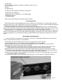
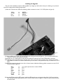
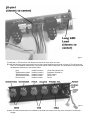
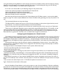
Etherwave® Plus Field Upgrade Instructions
The Etherwave Plus Field Upgrade is an advanced project for upgrading a standard Moog Music Etherwave theremin
to the Etherwave Plus. The new features of the Etherwave Plus include:
• Pitch CV Output – The Pitch Antenna can act as a CV (Control Voltage) controller for any external CV compatible
device, such as Moogerfooger® analog effects, the Minimoog Voyager® analog synthesizer, the Little Phatty® analog
synthesizer or the Moog Guitar. The Pitch CV is generated from the pitch of the theremin waveform. Nominal output
is -2.5V to + 4.5V. Zero Volts is output when the theremin produces a pitch one octave below middle C (approx.
131Hz). The Pitch CV output is factory-calibrated to produce a change of 1 Volt per octave change in the theremin’s
pitch.
• Volume CV Output – The Volume Antenna can act as a CV controller for any external CV-compatible device. The
Volume CV output is generated from the same CV signal used internally for the Etherwave’s VCA circuitry. Nominal
output is 0 to +10V.
• Gate Output – The Gate signal can be used as a signal to start envelopes, trigger sample and hold circuits or other
timing related activities.The Gate signal is generated when the Volume CV rises above 0 Volts AND when the theremin audio is greater than 0 Hz. OFF is 0 Volts and +10V is ON.
• Headphone Output with headphone volume control – can be configured with an internal jumper for normal or
“pitch preview” function.
• Power Indicator LED - indicates when the unit is on and ready to play.
This User’s Guide only describes the installation of the upgrade and the use of the added functions of the Etherwave
Plus. For information regarding the operation of the Etherwave Plus’ basic theremin functions, please refer to the Sections “Setting Up and Playing the Moog Music Etherwave Theremin” in the Etherwave Theremin User’s Manual. The
manual also assumes knowledge of basic theremin functions and terms.
The Upgrade
The upgrade procedure requires the following skills:
• Use of basic hand tools
• Precision drilling of three 1/2” holes with 7/8” counterbores into the wooden cabinet.
• Soldering wire harnesses and panel components to a PCB (Printed Circuit Board).
• Calibration of the Etherwave.
Caution: If you do not have these skills, then we recommend the Etherwave Plus factory upgrade
for your Etherwave.
Tools and materials required for the Upgrade:
• #2 Phillips screwdriver
• Small flathead screwdriver (1/8”)
• 15mm socket
• 11mm nutdriver, socket or wrench for installing pots
• 1/2” nutdriver, socket or wrench for installing jacks
• Wire cutters
• Wire stripper (for 22AWG wire)
• Voltmeter
• Calibration tool (included with kit)
• ESD-safe work bench
• Drill press or hand drill
• 7/8” Forstner drill bit
• 1/2” drill bit
• Center punch for marking location of holes to be
drilled.
• Scotch or masking tape
• Soldering iron appropriate for electronics assembly
• Solder appropriate for electronics assembly
Getting started
Before you begin, verify the following parts are included in the kit:
(1) 11-213 PCB assembly
(3) 15mm nylon hex nuts
(1) Etherwave Plus Front Panel
(1) 5-wire harness
(2) 50K linear taper potentiometers (labeled 50KB) w/ hardware: lockwasher, washer, and nut.
(2) 5K linear taper potentiometers (labeled 5KB) w/ hardware: lockwasher, washer, and nut.
(1) 50K audio taper potentiometer (labeled 50KA) w/ hardware: lockwasher, washer, and nut.
(1) #6 Locking terminal
(1) LED
(1) LED spacer
(2) 1/4” TRS Jack assemblies w/ hardware: lockwasher, washer, and nut.
(1) power switch
(1) knob
(1) calibration tool
The Etherwave Plus Upgrade is divided into 4 basic parts:
• Disassembly of the Etherwave
• Drilling the holes for installing the 11-213 PCB assembly
• Installing the Upgrade
• Tuning and testing
Please read and understand all the steps below before proceeding.
A note about ESD
ESD stands for Electrostatic Discharge. Have you ever walked across a carpeted room, touched a light switch and
received a shock? This is a form of ESD. ESD is more common when the air is very dry, and static charges easily build up
on the body or clothing if you move around on carpeted or wood flooring.
ESD can damage electronic components such as Semiconductors and Integrated Circuits. You can discharge static
electricity into these types of components without feeling anything and still cause damage. Both of these types of components are used on the 11-211 Etherwave circuit board and on the 11-213 Etherwave Plus circuit board.
Simple precautions can avoid damage to your circuits. Remember to touch a grounded surface before handling circuit
boards or components when they are outside of ESD-safe packaging. If you leave your work area and return, discharge
any static charge built up on your body by touching a grounded surface. Avoid touching the components on a circuit
board.
Disassembly of the Etherwave.
In order to drill holes in the bottom of the cabinet, it is necessary to disassemble the Etherwave. Save the screws
that are removed from the unit until it is re-assembled.
1) If necessary, disconnect the Etherwave from the power supply and remove the antennas.
2) Turn the Etherwave over, remove the three screws holding on the mic stand adapter.
3) Remove the 4 screws (2 each on the front and back) that fasten the cover and take the cover off the unit.
4) Unplug the front panel from connector CN1 on the PCB.
5) De-solder the bus wire connecting the PCB to the antennas’ hardware at the PCB, and remove the 5 screws
holding the Etherwave PCB in place. Remove the PCB and place somewhere safe and static-free.
6) Remove the three screws on the bottom of the cabinet fastening the front panel and remove the front panel.
7) Disconnect the grey and white wires from the power switch. Cut the following wires where they are soldered to
the pots or jack: Yellow, Brown, Orange, Red, Violet, Blue, Green, Black. (see figure 1)
8) Once the 10-wire harness is disconnected from the front panel, cut all wires to match the length of the shortest
wires (blue and green are the shortest).
9) Remove the four knobs from the front panel by loosening their set screws with a 1/8” flathead screwdriver.
figure 1
Drilling the holes for the 11-213 PCB
The drilling of the holes for the 11-213 PCB involves marking the location of the holes, counterboring three 7/8”
holes and drilling a 1/2” hole through the cabinet at the center of each counterbore. A counterbore is a term for a hole
that is not drilled completely through a surface and forms a cylindrical cutout in the surface that is drilled. The bottom
of a well made counterbore should be flat. In the following operations, accuracy is important, as is proper depth of the
counterbore. Figure 3 below shows a properly drilled counterbore.
1) Find the drill template at the back of this manual. Align the drill template on the bottom of the cabinet according
to the instructions on the template. (see figure 2)
2) Mark the holes to be drilled with a center punch. (see figure 2)
3) Check the holes – they all should be 1” from the front edge of the cabinet, the hole for the Gate Output should be
1 1/4” from the center of the cabinet.
4) With a 7/8” Forstner drill bit, set up your drill so you will counterbore the holes leaving 3/16” of material
between the bottom of the holes and the inside surface of the cabinet. If using a hand drill this can be done by
marking the drill bit with a piece of masking tape or with a paint marker 5/16” distance from the tip of
the drill’s cutting edge. Stop drilling when the mark reaches the surface of the wood.
figure 2
5) Carefully counterbore the 7/8” holes to the proper depth. CAUTION: DO NOT DRILL ALL THE WAY
THROUGH THE CABINET.
6) Prepare your drill for drilling a 1/2” diameter hole with the 1/2” drill bit.
7) At the center of the counterbore, drill a 1/2” hole through the bottom of the cabinet. See figure 3 for an
example of how a counterbore should look when complete.
figure 3
Installing the Upgrade
This part of the installation requires soldering. Before you begin, you will need to have your soldering iron powered
up and at an appropriate soldering temperature.
1) Select the 5-wire harness. Make the following solder connections to the 11-211 PCB (shown in figure 4):
Yellow
Orange
Red
Brown
to
to
to
to
AUDIO
AMP OUT
AMP IN
VCA OUT
figure 4
2) Solder the Black wire of the 5-pin harness to the #6 locking terminal (see figure 4). Trim any excess leads of the
other four wires on the bottom of the PCB.
3) Reinstall the 11-211 Etherwave Circuit board and solder the antenna wires to the PCB antenna connectors.
4) Excluding the Grey and White wires, strip the wires of the 10-wire harness to expose 3/16” of bare wire and tin
them. Make sure there is not excess solder built up on the wires, or they will not be easy to install in the 11-213
PCB.
5) With the 8 stripped and tinned wires of the 10-wire harness, Make the following solder connections to the 12-213
PCB (as shown in figure 5):
Black
Green
Blue
Violet
Red
Orange
Brown
Yellow
to
to
to
to
to
to
to
to
J1-1 (square pad, closest to center of PCB)
J1-2
J1-3
J1-4
J1-5
J1-6
J1-7
J1-8
6) Insert the LED through the LED spacer. Install the LED into the non-component side of the 11-213 with the long
lead inserted into the square pad (closest to center of PCB; shown in figure 5). Solder the LED in place and trim
the excess leads.
figure 5
7) Install the 11-213 board into the cabinet with the three 15mm nylon hex nuts.
8) Install the following panel components into the front panel locations listed (shown in figure 6). For the pots and
jacks, use a lockwasher between the component and the inside of the panel. On the outside of the panel install
the flatwasher between the nut and the panel:
Jacks
50KB potentiometers
5KB potentiometers
50KA potentiometer
Power switch
install in locations
install in locations
install in locations
install in location
install in location
Audio Out, Phones Out
Brightness, Waveform
Pitch, Volume
Phones Vol.
Power
figure 6
9) Make sure the Potentiometers are installed so the leads are closest to the top of the enclosure are uniformly
straight.
figure 7
10) Slowly place the panel onto the front of the cabinet so the potentiometer leads stick through the
appropriate pads on the 11-213 PCB (shown in figure 7).
11) Holding the panel in place, flip the unit over and install the three screws that fasten the panel to the bottom of
the cabinet.
12) Reinstall the mic stand adapter.
13) Turn the unit over. Solder the pot leads to the PCB.
14) Make the following connections (final result shown in figure 8):
5-wire harness connector
10-wire connector
#6 locking terminal
Phones Out
Audio Out
Grey/white wires
to
to
to
to
to
to
11-213 PCB connector labeled J2
11-211 PCB connector labeled CN1
Foil strip (screw terminal down)
11-213 PCB connector labeled J7
11-213 PCB connector labeled J8
Power switch terminals
figure 8
15) Turn the pots all the way down (full CCW). Install the knobs so the indicators point to 7:00.
Tuning and Testing
With all the components installed and connected, the next step is to make adjustments to the Etherwave’s tuning,
and try out the new features.
1) Install the theremin antennas.
2) Install the theremin on a mic stand.
3) Connect the Audio out to an amplifier.
4) Connect power. Turn the Etherwave Plus power on. The Power LED should light up red. If not, turn the power off
and see the troubleshooting section of the manual.
5) Set the Pitch tuning control to 9:00.
6) Adjust the amplifier so you are monitoring the theremin audio at a comfortable level. If you are not hearing any
theremin audio, proceed to the troubleshooting section.
7) Is zero beat at arm’s length from the pitch antenna? If not, then the theremin’s Fixed Pitch Oscillator (FPO) needs
adjustment.
8) Tune the FPO by adjusting L6 so that zero beat occurs when you are arm’s length from the pitch antenna, and the
Etherwave’s pitch rises smoothly as you approach the pitch antenna.
9) Replace cover – set the Pitch tuning control to 12:00, and check the position of zero beat. It should be at about
arm’s length from the pitch antenna. Repeat FPO adjustment if necessary.
10) Verify the function of the following front panel knobs: Volume tuning, Pitch tuning, Waveform, and Brightness.
11) Connect the voltmeter to the Gate output. Verify a +10V gate signal when the left hand is away from the volume
antenna AND your right hand is close to the pitch antenna (theremin audio must not be at zero beat).
12) Connect the voltmeter to the Volume CV output – verify an output of 0 to +10V as the left hand moves from
very close to far away from the volume antenna.
13) Connect the voltmeter to the Pitch CV output – verify an output that increases when approaching the pitch
antenna and decreases when moving away from the pitch antenna. The nominal level is set to -2.5V to +4.5V
for musical control, but will vary a little unit to unit because the voltage is derived from the frequency of the
theremin audio. Touching the pitch antenna may produce a CV as high as +7V. It takes two full cycles of the
theremin’s waveform to derive the Pitch CV output. When playing in the bass region, or making sudden moves
in the bass region of the theremin, the voltage may seem discontinuous, like a classic sample-and hold effect.
This is normal. When the theremin is at zero beat, the Pitch CV settles at the last voltage derived.
14) Connect a pair of headphones to the Phones out. Verify function of Phones level. To configure the headphone
output as a pitch preview see the section below called “Configuring the Headphones for “Pitch Preview”.
Congratulations – now you are ready to use the Etherwave Plus!
Using the Etherwave Plus
Below is a diagram of the Etherwave Plus Front Panel indicating the Panel Controls and Connections (figure 9).
figure 9
What is a CV?
CV stands for Control Voltage. In analog electronic musical instruments, it is a type of low-current electrical signal
used to continuously modulate a musical parameter. In the Etherwave theremin, the simplest example of a CV is the
control of the instrument’s volume by the Volume Antenna. The Volume Antenna circuitry generates a CV that increases as the left hand is pulled away from the antenna. This CV is applied to the control input of a Voltage Controlled
Amplifier (VCA). As the voltage generated by the Volume Antenna circuitry increases, the output level of the VCA
increases too. We hear this as an increase in volume. For more on the subject, you may wish to refer to the “Basics of
Analog Synthesis” chapter of the Minimoog Voyager User’s Manual, or the “Basic Theory” section of the CP-251 Control Processor User’s Manual, both available on our website: www.moogmusic.com.
What is a Gate?
A Gate is a signal that has only two levels: Low and High, or sometimes called Off and On. This can be used as a trigger for events, or as a switch type signal. In analog synthesizers, a gate is usually used to start or stop the sound of the
instrument by starting and stopping circuits called Envelope Generators. For example, a gate on signal is produced when
a key is pressed on the Minimoog Voyager, thus starting a note.
Using the Etherwave Plus CV Outputs.
The Etherwave Plus CV outputs are located on the bottom of the unit as indicated by the front panel, requiring the
placement of the Etherwave Plus on a mic stand to provide access. CAUTION: Be sure you understand the operating
levels of the equipment involved before making connections. Most modern analog equipment has protection built into
the inputs of a circuit to prevent damage from unexpected voltage levels. However some equipment may respond in
unexpected ways, or may not respond at all to CVs outside the expected levels.
Note that most modern Moog equipment such as moogerfooger analog effects typically specify 0V to +5V or -5V
to +5V levels for CV inputs. The Etherwave Plus will work safely with these devices despite outputting voltages greater
than specified. In general it is safe to make connections with the equipment powered up.
One thing to avoid when making CV connections is to avoid passively mixing CV output signals into a single CV
input, for instance with a “Y” type splitter cable. This can sum the voltages involved and rapidly exceed the voltage levels
expected at a CV input. This may cause unwanted results. For combining CV signals, use a CV mixer, such as the 4-input
mixer of the moogerfooger CP-251 Control Processor.
Example Application: Connecting the Etherwave Plus to a Little Phatty analog synthesizer.
In this example we will control the Little Phatty so that it can be played in a gestural manner similar to a theremin.
• First, connect the Etherwave Plus Gate Output to the Little Phatty(LP) Gate input.
• Second, connect the Pitch CV Output to the LP Pitch control input.
• Next, Connect the Volume CV Output to the LP Volume control input.
• On the LP, select a single oscillator preset that is voiced in the 16’ range and has a sustaining type envelope.
Now – with your left hand away from the Volume Antenna, Move your right hand closer to the Pitch Antenna – note
the LP pitch rises. Now move your left hand close to the Volume Antenna – you will hear the LP go silent – as you lift
your left hand away from the Volume Antenna you will hear the LP start a note again.
It is really fun to try different presets out to hear the ways the Little Phatty will respond to the gestural control of the
Etherwave Plus!
Example Application: Connecting the Etherwave Plus to a MF-102 Ring Modulator.
In this example we will control the MF-102’s built-in Carrier Oscillator, which is combined with the audio of the
theremin itself in the Ring Modulator to produce sum and difference frequencies.
• First, connect the Audio Output of the Etherwave Plus to the Audio Input of the MF-102.
• While making sound with the theremin, adjust the Drive Control of the MF-102 so the Drive LED is YELLOW.
• Set the MF-102 Frequency Control to 120 Hz (Hi Range).
• Now connect the Pitch CV Output to the MF-102 Frequency Input.
• Set the Mix Control to full CCW and the LFO Amount to full CCW.
• Connect the Volume CV Output to the MF-102 Mix Input.
Now as you move your left hand away from the Volume Antenna, the volume of the audio increases, as does the
volume of the ring modulator effect. When your left hand is away from the Volume Antenna, what you hear is 100% the
effected signal. As your right hand moves in proximity to the Pitch Antenna you will hear the variation of the difference
tones generated by the Ring Modulator as both the pitch of the Carrier Oscillator and the theremin audio are changing.
Note: for more information on the operation of the MF-102, refer to “Understanding and Using your MF-102 Ring
Modulator” manual, available on our website www.moogmusic.com.
For an even more intense effect, try the following changes to the previous setup:
• Connect the Volume CV Output to the LFO Rate Input of the MF-102.
• Now set the Mix and LFO Amount to full clockwise.
• Set the LFO Waveform switch to the square wave position.
• Place the LFO Rate Control in mid-position.
Now when your left hand moves away from the Volume Antenna, the LFO Rate increases – even into the audible
frequency range. This creates complex sidebands in the Carrier Oscillator itself, generating some very hairy timbres. Far
out!
This last example illustrates two important things:
• The Etherwave Plus’ antennas don’t have to control the same parameter on other pieces of gear that they control
on the theremin – for instance the Volume Antenna can control the LFO Rate.
• There are many ways to use gestural control of electronic musical instruments. Hook it up and try it. Experiment!
These are just a couple quick examples to get you started with using the Etherwave Plus as a CV controller. As the
variety of modern analog CV-compatible equipment increases, so to does the wealth of opportunities for the use of
your Etherwave Plus as an expressive gestural controller for your sonic explorations. For more applications using the
Etherwave Plus as a gestural CV Controller, visit our website www.moogmusic.com/theremin/.
Configuring the Headphones for “Pitch Preview”
The Headphone Output of the Etherwave Plus is designed to drive a pair of headphones with a minimum of 32 Ohms
impedance. The level of the Headphones signal is set by the “Phones Vol.” panel control. It is not recommended to use
the Headphone Output with a 2-conductor, Tip-sleeve 1⁄4” instrument plug for an alternate audio output. As configured
from the factory, the Headphone Output is generated from the Etherwave Plus’ audio output for practicing using headphones.
Some theremin users like to hear the theremin’s waveform independently of volume control – the so-called “pitch
preview” function. The Headphone Output can be configured for this feature by moving an internal jumper on the Etherwave Plus circuit board.
To change the function of the Headphone Output to pitch preview, follow these steps:
• Disconnect the Etherwave Plus from the power adapter.
• Remove the Etherwave Plus cover.
• Touch a grounded surface to discharge any static electric charge that may be built up on your hands before touching
any components inside.
• Looking at the vertically mounted PCB (p/n 11-213) located between the panel and the standard Etherwave theremin
PCB (p/n 11-211), find where the Audio Output jack is plugged into the PCB - this connector is labeled J8. Unplug this
connection.
• Underneath this connection is a 3-pin connector labeled J6 with a jumper connecting the pin closest to the center of
the unit to the middle pin of the connector. Move this jumper to connect the middle pin to the pin closest to the output
jacks.
• Now reconnect the Audio Output to the 11-213 PCB, and replace the instrument’s cover.
Figure 10 below shows the location of the jumper.
Now the Headphone Output delivers a pitch preview output to a pair of stereo headphones. With this modification
the performer can monitor the current pitch with headphones even when the left hand is shutting off the Audio Output.
The performer can then play the desired frequency with the right hand before articulating the note with the left hand.
This can be very useful in studio or even live situations where pitch accuracy is required at the onset of the note played.
Troubleshooting:
figure 10
Power LED does not come on.
Check the power connection. Measure the +12 and -12 Volt test points to verify the correct voltages. Check that the
LED is soldered in correctly. Check that the 10-wire harness is soldered and connected correctly. Check for shorts or
solder chips floating around inside the unit.
No Audio Output
Is the Etherwave Plus on a table? If so, mount it on a mic stand. Verify that no objects are close enough to the Volume
antenna to turn off the audio output. Verify that the Audio Output jack is connected correctly. Check that the 10-wire
harness is soldered and connected correctly. Check for shorts or solder chips floating around inside the unit. Temporarily short C28 (connects VCA Out to Ground). If you hear audio output then L11 needs adjustment. If not, then the VCA
(U3) may have been damaged.
No Gate Output
Is the Etherwave Plus at zero beat? If so, the Gate Output will be OFF. Check that the 5-wire harness is soldered and
connected correctly. Check that the Volume CV output is working correctly.
No Volume CV Output
Is the Etherwave Plus volume antenna working correctly? If not, see Audio out troubleshooting above. Check that the
5-wire harness is soldered and connected correctly.
No Pitch CV Output
Is the Etherwave Plus at zero beat? If so, the Pitch CV will produce a fixed voltage and won’t change until the Etherwave
produces audio. Check that the 5-wire harness is soldered and connected correctly.
No Headphone Output
Verify that the Jumper is installed on 11-213 J6. Check that the headphone output connector is installed correctly. Make
sure that the Phones Volume control is soldered correctly and is not in the full CCW position.
For further assistance with troubleshooting Contact Moog Music tech support by calling the number below, or by emailing [email protected]. Moog Music technicians are available for support Monday through Friday 9:00AM to
5:00 PM EST.
Specifications subject to change without notice.
Etherwave, Moogerfooger, Minimoog, and Voyager are all registered trademarks of Moog Music Inc.
© 2009 Moog Music Inc. All Rights Reserved
Moog Music Inc. 160 Broadway St. Asheville NC 28801 USA
phone: 828-251-0090 web: www.moogmusic.com
This edge should
be lined up with
the front edge
of the cabinet
on the bottom of
the cabinet.
These three holes should line up with the holes drilled for the front panel
1) Cut out the rectangle below. Be sure to use a straightedge and cut the bottom edge accurately.
2) Prepare three small pieces of scotch or masking tape to fix the template in place.
3) Line the bottom edge of the template up with the front panel edge of the cabinet.
4) Line the center small hole up with the center hole for the front panel.
5) Tape the template in place without allowing it to move.
6) Using your center punch, mark the center of the three large holes into the bottom of the Etherwave Cabinet,
7) Remove the template and proceed with drilling the holes as described in the manual.
Instructions:
This template is used for marking the locations on the bottom of the cabinet for the three holes that must be drilled to mount the
11-213 PCB assembly.
ETHERWAVE PLUS:
TEMPLATE FOR MARKING LOCATION OF HOLES
th