1
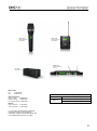
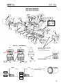
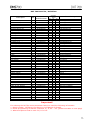
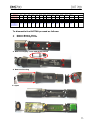
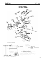
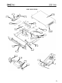
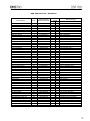
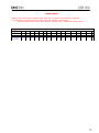
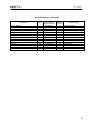
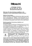
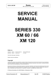
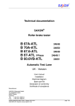
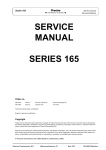
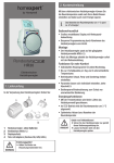
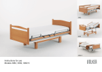
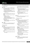
AKG CUSTOMER SERVICE DEPARTMENT / Laxenburger Straße 254 / 1230 Vienna, Austria TEL: +43 1 866 54-0 / FAX: +43 1 866 54-1514 / [email protected] / www.akg.com Table of contents: The complete DSM 700 family DHT 700 Digital handheld transmitter DPT 700 Digital bodypack transmitter DSR 700 Digital stationary receiver CU 700 Charging unit Last modification : Page 5, pos.7 and 8. visa versa Page 8, new number for MiniXLR socket added V2 added Page 11, screw quantity corrected Page 13, added CU700 Page 4, corrected wiring front panel number removed D7 version added Page 11, pos 21 new number Page 6, add dismantle DHT700 3 4 7 9 13 Die komplette DMS 700 Familie DHT 700 Digitaler Handsender DPT 700 Digitaler Taschensender DSR 700 Digital Empfänger CU 700 Ladegerät DHT 700 Digital handheld transmitter DPT 700 Digital bodypack transmitter DSR 700 Digital stationary receiver CU 700 Charging unit Mains cable: EU 0110E03160 US 0110E03170 DSR 700 Antenna: Band 1 (long) 9999N07440 Band 2 (short) 9999N07450 Front mount cable 0110E01890 Manual: User manual V1 User manual V2 9100U12810 9100U13560 For information about PSU4000, HUB4000Q, PS4000 and antenna system SRA2B/W, RA4000B/W, AB4000 and ASU4000 please refer to the WMS4000/4500 Service information. Band 1 Band 2 Frequency range, Mhz, 548,100 – 697,900 / 50mW 710,100 – 861,900 / 50mW 863,100 – 864,900 / 10mW DHT 700 D5 3157Z00… DHT 700 C5 3157Z00… DHT 700 D7 3157Z00… 37 19 1 21 32 8 10 3 30 31 14 33 16 15 22 20 23 17 2 27 24 4 5 29 13 9 25,26 35 7 19 34 33 11 12 28 32 Wiring / Verkabelung D5 inphase (red) D7 C5 Sleeve 5 to be glued on end cap 9 after it is completely screwed onto part 4 (thread part). Use UHU PLUS ENDFEST 300. inphase (red) Cut out of end cap 6 has to be align with charging contacts! 36 non corrosive silicon glue 36 D5/D7 C5 Apply Loctite 415 to secure transducer capsule. red blue screen black red 6 DHT 700 Parts list / Stückliste Description Wire-mesh cap Wire-mesh cap Wire-mesh cap Foam insert Foam insert Electret capsule C5 Dynamik capsule D5 Dynamik capsule D7 Housing with thread Battery sleeve End cap Housing shell, lower Housing shell, upper Contact cover Half ring, upper Half ring, lower Battery clamp Friction Display cover Mute button Foam Foam Display holder Foam LCD display On/Off button IR window Foam Main board Band 1 Main board Band 2 Antenna board Band 1 Antenna board Band 2 Clamp cushion Contact support Battery contact Battery contact Screw EJOT PT KB18x6 Screw EJOT PT KB22x8 Screw EJOT PT KB22x8 Screw EJOT PT KB25x10 Cable for D5 capsule Device sticker DHT 700 D5 Device sticker DHT 700 C5 Device sticker DHT 700 D7 Standadapter SA63 Windscreen Colorbandset Adapter PB1000 Quantity Stück Bezeichnung Pos. Part number Bestellnummer C5 D5 D7 1 1 1 2 2 3 3 3 4 5 6 7 8 9 10 11 12 13 14 15 16 17 19 20 21 22 23 24 25 26 27 27 28 29 30 31 32 33 34 35 36 37 37 37 - 3157M12010 3157M12020 3157M12030 3138Z25020 3138Z25010 3157M15010 2610Z00050 2610Z00070 3157M14010 3157Z19020 3157Z20010 3157Z11010 3157Z10010 3157Z42010 3157Z21010 3157Z31010 3157M10010 3157Z40010 3157M13010 3157Z14010 3157Z37010 3157Z38010 3157Z15010 3157Z28010 0050E00070 3157Z16010 3157Z17010 3157Z27010 3157M01010 3157M01020 3157M02010 3157M02020 3157Z48010 3157Z47010 3157Z22010 3157Z23010 0099N18050 0099N22140 0099N22040 0099N25050 2548K00010 4808S10… 4809S10… 4813S10… 6000H63050 2630Z01040 2630Z00210 2334Z05010 1 1 1 1 1 1 1 1 1 1 1 1 1 1 1 1 1 1 2 1 1 1 1 1 1 1 1 1 4 2 2 2 3 2 1 1 1 1 1 1 1 1 1 1 1 1 1 1 1 1 1 1 1 1 1 1 1 1 2 1 1 1 1 1 1 1 1 1 4 2 2 2 3 2 1 1 1 1 1 1 - 1 1 1 1 1 1 1 1 1 1 1 1 1 1 1 1 1 1 2 1 1 1 1 1 1 1 1 1 4 2 2 2 3 2 1 1 1 1 1 1 - Gitterkappe Gitterkappe Gitterkappe Innenwindschutz Innenwindschutz Elektretkapsel C5 Dynamische Kapsel D5 Dynamische Kapsel D7 Gehäuse mit Gewindeteil Batteriehülse Kappe Untere Gehäuseschale Obere Gehäuseschale Kontaktabdeckung Halbring, oben Halbring, unten Batterieklammer Reibung Display Abdeckung Mute Knopf Schaumstoffstück Schaumstoffstück Displayhalter Schaumstoffstück LCD Display ON/Off Knopf IR Fenster Schaumstoffstück Hauptprint Band1 Hauptprint Band 2 Antennenprint Band 1 Antennenprint Band 2 Auflage Kontaktfederung Batteriekontakt Batteriekontakt Schraube PT KB18x6 Schraube PT KB22x8 Schraube PT KB22x8 Schraube PT KB25x10 Kabel für D5 Kapsel Geräteaufkleber DHT 700 D5 Geräteaufkleber DHT 700 C5 Geräteaufkleber DHT 700 D7 Stativklammer Windschutz Farbbandset Vorsatz PB1000 Important! For ordering the DHT700 main transmitter board we need the following information: 1. Board number: 3157M0101 for Band1 or 3157M0102 for Band2 2. Preset programming for Band2: standard, IL, IT, BY……etc. (please see table on next page) 3. What microphone head is used: D5, D7 or C5. Frequency band and power / Frequenzband und Leistung Preset-- Main board 3157M01010 3157M01020 Device sticker D5-4808S10… C5-4809S10… D7-4813S10… BD1 50mW BD1 U 50mW BD2 10/50mW BD2 RO 30mW B2 NZ 10/50mW BD2 AU 50mW BD2 JP 10mW BD2 TH 50mW BD2 HK 10/20mW BD2 KR 10mW BD2 BY 50mW BD2 IT 10/50mW BD2 IL 10mW x x x x x x x x x x x x x 130 020 030 040 050 060 070 080 090 100 110 120 - 010 To dismantle the DHT700 proceed as follows: 1. 2. Remove Battery sleeve Remove housing screws 3. Remove display cover and mute button 4. Remove housing 5. Open DPT 700 3156Z00… DPT 700V2 3156Z02… 1 19,20 11 12 5 10 7 4 6 3 9 8 18 13 14 2 15 16 14 17 Wiring / Verkabelung All charging contact solder joints: 1. pre-solder related pads on pcb 2. assemble pcb and frame assy. 3. melt solder by heating up charging contacts with soldering tip (apply some pressure) All cables from pcb carrier assy. To be soldered directly on charging contacts like shown in this view DPT 700 Parts list / Stückliste Description Part number Bestellnummer Pos. Quantity Stück Housing compl.*, upper Housing, bottom Battery cover assy. Frame assy. Frame assy. LCD display Display holder Foam Antenna assy. Band 1 Antenna assy. Band 2 Foam On/Off button Mute button Cover Mainboard Band 1** 1 2 3 4 4 5 6 7 8 8 9 10 11 12 13 3156M11010 3156Z11010 3156M14010 3156M12010 3156M12020 0050E00070 3156Z17010 3157Z28010 3156M10020 3156M10010 2932Z34010 3156Z18010 3156Z19010 3156Z20010 3156M01010 V1 1 1 1 1 1 1 2 1 1 1 1 1 1 1 Mainboard Band 2** Bolt, DIN7 2h8 x 20mm Belt clip Screw, M2.5x10 Device sticker Device sticker Foam Mini-XLR socket with wires Nut for Mini-XLR socket 13 14 15 16 17 17 18 19 20 3156M01020 0007D20050 3156Z25010 7045D25030 4807S00… 4807S12… 2932Z21010 3156M15010 2781Z20020 1 2 1 3 1 2 1 1 V2 1 1 1 1 1 1 1 1 1 1 1 1 1 1 1 2 1 3 1 2 1 1 Bezeichnung Gehäuseoberteil kompl.* Gehäuseunterteil Batteriedeckel Rahmen kompl. Rahmen kompl. LCD Display Displayhalter Schaumstoffstück Antenne kompl. Band 1 Antenne kompl. Band 2 Schaumstoffstück On/Off Knopf Mute Knopf Abdeckung Hauptprint Band 1** Hauptprint Band 2** Stift, DIN7 2h8 x 20mm Gürtelklammer Schraube, M2.5x10 Geräteaufkleber Geräteaufkleber Schaumstoffstück Mini-XLR Buchse Mutter für Mini-XLR Buchse * Housing compl. upper includes display window and Mini-XLR socket. **Mainboard (13) will always delivered together with frame assy. (4) Important! For ordering the DPT700 main transmitter board we need the following information: Board number: 3156M0101 for Band1 or 3156M0102 for Band2, V1 or V2. Preset programming for Band1: BD1 or BD1U (please see below table) Preset programming for Band2: IL, IT, BY……etc.(please see below table) Frequency band and power / Frequenzband und Leistung Preset-- Main board 3156M01010 3156M01020 Device sticker V1 4807S00… V2 4807S12… BD1 50mW BD1 U 50mW BD2 10/50mW BD2 RO 30mW B2 NZ 10/50mW BD2 AU 50mW BD2 JP 10mW BD2 TH 50mW BD2 HK 10/20mW BD2 KR 10mW BD2 BY 50mW BD2 IT 10/50mW BD2 IL 10mW x x x x x x x x x x x x x 020 030 040 050 060 070 080 090 100 110 120 - 010 130 DSR 700 3155Z00… 3 1 13 4 5 12 7 20,21 2 8 10 39 9 2 13 11 17 6 23 4 3 40 24 22 15,16 Frontpanel 36 36 37 32 30 21 42 24 33 41 28 34 25 31 29 35 27 22 3 26 43 23 38 DSR 700 Parts list / Stückliste Description Housing, upper Housing, bottom Power supply unit IEC power socket Isolation plate Cable assy. DSP Main board DSP Main board RF board Band 1 RF board Band 2 Data cable Data cable Screw EJOT PT DG 40x8 Screw EJOT PT KB 30x8 Screw M3x8 Screw B2,9x6,5 Lockwasher Screw EJOT PT DG 30x8 Lockwasher BNC nut Front panel Front panel “Power” button Jog-button Power switch “Back” button Rocker-switch assy. Light guide “Channel” button, left “Channel” button, right “FX” button Headphone socket 6,3mm Front board assy. Display holder LCD display Display gasket Screw EJOT PT DG 30x8 Screw EJOT PT DG 30x6 Cover part Device sticker Device sticker Grommet Jog dial switch Push switch Self-adhesive front foil Self-adhesive front foil Antenna Bd1 (long) Antenna Bd2 (short) Mains cable EU Mains cable US Pos. Part number Bestellnummer 1 2 3 4 5 6 7 7 8 8 9 10 11 12 13 15 16 17 18 19 21 21 22 23 24 25 26 27 28 29 30 31 32 33 34 35 36 37 38 39 39 40 41 42 43 43 - 3155Z11010 3155M10010 3155M04010 0017E15070 3155Z45010 0110E03220 3155M02010 3155M06010 3155M05010 3155M05020 0016E18240 0016E18230 0099N40040 0099N30080 7985D30010 7981D29070 0128D03000 9999N07810 9999N06050 2841Z10010 3155M20010 3155M20020 3155Z23010 3155M21010 0040E06460 3155Z26010 3155M22010 3155Z27010 3155Z25010 3155Z25020 3155M23010 0017E03600 3155M03010 3155M24010 0050E00080 3155Z33010 0099N30180 0099N30150 3155Z36010 4810S00 … 4810S12 … 7261N30040 0040E06500 9040E00160 3155Z30010 3155Z30020 9999N07440 9999N07450 0110E03160 0110E03170 Quantity Stück V1 V2 1 1 1 1 2 1 1 1 1 1 1 4 6 8 7 7 2 3 3 1 1 1 1 1 1 2 1 1 1 1 1 1 1 1 9 2 2 1 2 1 6 1 2 2 1 1 1 1 1 1 1 1 1 1 1 1 1 4 6 8 7 7 2 3 3 1 1 1 1 1 1 2 1 1 1 1 1 1 1 1 9 2 2 1 2 1 6 1 2 2 1 1 Bezeichnung Gehäuseoberteil Gehäuseunterteil Netzteil IEC Einbaustecker Isolationplatte Kabel DSP Hauptprint DSP Hauptprint HF Print Band 1 HF Print Band 2 Datenkabel Datenkabel Schraube EJOT PT DG 40x8 Schraube EJOT PT KB 30x8 Schraube M3x8 Schraube B2,9x6,5 Sicherungsscheibe Schraube EJOT PT DG 30x8 Sicherungsscheibe BNC Mutter Frontplatte Frontplatte “Power” Knopf Jog-Knopf Hauptschalter “Back” Knopf Rocker-Schalter assy. Lichtleiter “Channel” Knopf, links “Channel” Knopf, rechts “FX” Knopf Kopfhörerbuchse 6,3mm Front Print assy. Displayhalter LCD Display Displaydichtung Schraube EJOT PT DG 30x8 Schraube EJOT PT DG 30x6 Abdeckung Geräteaufkleber Geräteaufkleber Tülle Dreh-Drück-Schalter Drückschalter Selbstklebende Frontfolie Selbstklebende Frontfolie Antenne Bd1 (lang) Antenne Bd2 (kurz) Netzkabel EU Netzkabel US Important! Always make a firmware update after DSP, RF, or display pcb has been replaced. For ordering the DSR 700 front board we need following information Preset programming: Bd1, Bd2, BD2/IL, BD2/IT…etc. (please see table below) Frequency band / Frequenzband Preset-- Front board 3155M03010 Device sticker V1 4810S00… V2 4810S12… BD1 BD1 U BD2 BD2 RO B2 NZ BD2 AU BD2 JP x x x x x x 010 130 020 030 040 050 BD2 TH BD2 HK BD2 KR BD2 BY BD2 IT BD2 IL x x x x x x x 060 070 080 090 100 110 120 CU 700 3158Z00010 Wiring / Verkabelung CU 700 Parts list / Stückliste Description Housing bottom DC-Jack socket Fan holder Fan Insert part assy. Main board Light guide Housing top Metall plate Screw EJOT PT KB 30x12 Housing foot Cable assy. Cable assy. Rechargeable battery, packing unit 4 pcs. Power supply 12V/2A EU,UK,US,AU Pos. 1 2 3 4 8 9 10 11 12 13 14 15 16 - Part number Quantity Bestellnummer Stück 3158Z12010 0016E03760 3158Z23010 0027E00710 3158M11120 3158M01010 3158Z13010 3158Z10010 3158Z21010 0099N30170 3158Z24010 3158M15010 3158M16010 0026E00270 7801H00110 1 2 2 1 2 1 2 1 1 4 4 2 2 4 1 Bezeichnung Gehäuseunterteil DC-Buchse Lüfterhalter Lüfter Einsteckteil Hauptprint Lichtleiter Gehäuseobertel Metallplatte Schraube EJOT PT KB 30x12 Gehäusefuß Kabel kompl. Kabel kompl. Akkus, Verpackungseinheit 4Stk. Netzteil 12V/2A EU,UK,US,AU