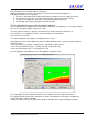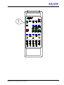
1
Technical documentation
SAXON®
Roller brake tester
B 67A-ATL
B 70A-ATL
B 67.6-ATL
B 67-ATL 1Phase
B 60.6VB-ATL
24648
24650
24649
24649 1
24651
Automatic Test Lane
UK - Version
User manual
Installation
Electrical diagram
Spare part list
Declaration of conformity
Certificate of acceptance
Manufacturer:
SAXON Prüftechnik GmbH
Am Stadtwald 19/23
08525 Plauen
Germany
Tel.:
++49 3741 5485 23
Fax.: ++40 3741 5485 42
SAXON Prüftechnik GmbH Plauen, Release: 29.01.2010
24648 B67A-ATL Operation manual englisch C.doc
page 1/44
Table of contents
1
2
3
4
5
6
Introduction..................................................................................................................................................3
Approvals and use MOT in UK....................................................................................................................3
Safety Instructions .......................................................................................................................................4
Packing, transport and storage ...................................................................................................................5
Mounting, installation and start-up ..............................................................................................................7
Displays and operating elements ................................................................................................................8
6.1
Display cabinet.....................................................................................................................................8
6.2
Function of the operating elements at the electrical cabinet................................................................9
6.3
Meaning of display elements ...............................................................................................................9
6.4
IR remote control................................................................................................................................11
6.5
Useful accessories .............................................................................................................................14
7 Starting the brake tester ............................................................................................................................14
8 ATL brake test mode .................................................................................................................................15
8.1
Standard sequence for performing a brake test ................................................................................15
8.2
Detailed description of tasks ..............................................................................................................15
8.2.1
The main screen .........................................................................................................................15
8.2.2
Create an order...........................................................................................................................16
8.2.3
Activate the order........................................................................................................................19
8.2.4
Perform the test ..........................................................................................................................20
8.2.5
Test the vehicle according the machine's guidance ...................................................................21
8.2.6
See the results ............................................................................................................................27
8.2.7
Evaluate the results as required by ATL specification and close the order................................28
8.2.8
Print the ATL test report..............................................................................................................29
8.2.9
Create a new basic data (Make, Models, Inspectors, Vehicle class) .........................................33
9 Operating in manual mode ........................................................................................................................35
9.1
Self test and start up procedure.........................................................................................................35
9.1.1
Error codes at the start up ..........................................................................................................35
9.1.2
Wrong manual entries.................................................................................................................35
9.2
Side slip test (not required for MOT)..................................................................................................36
9.3
Chassis tester check (not required for MOT).....................................................................................36
9.4
Brake test for MOT.............................................................................................................................37
9.4.1
Normal test process ....................................................................................................................37
9.4.2
Special operation steps ..............................................................................................................37
9.4.3
Testing vehicles with 4WD..........................................................................................................38
9.4.4
Testing vehicles class I + II.........................................................................................................38
10
Special evaluations for side slip and suspension tester ........................................................................39
10.1
Side slip test evaluation ..............................................................................................................39
10.2
Chassis test evaluation...............................................................................................................39
11
Maintenance, instrument test and customer service .............................................................................41
11.1
Maintenance ...............................................................................................................................41
11.2
Instrument Test...........................................................................................................................42
11.3
Customer Service .......................................................................................................................42
12
Annex.....................................................................................................................................................43
12.1
Technical Data ............................................................................................................................43
12.2
Installation...................................................................................................................................44
12.3
Electrical diagram .......................................................................................................................44
12.4
Spare part list..............................................................................................................................44
12.5
Declaration of conformity ............................................................................................................44
12.6
Certificate of acceptance ............................................................................................................44
SAXON Prüftechnik GmbH Plauen, Release: 29.01.2010
24648 B67A-ATL Operation manual englisch C.doc
page 2/44
1 Introduction
®
We congratulate you on having purchased a new SAXON roller brake tester.
The brake tester is a combination of a well-proved and tested computer-controlled electronic system, a
highly developed software system, and a top quality mechanical system.
With the appropriate options, the tester can be used for checking track angles, shock absorbers as well as
braking systems.
Whether you can use all the elements and operating functions specified herein depends on the equipment
provided on your brake tester. We do not assume any guarantee for the error-free operation of functions
which are not specified herein.
The modular system of the tester allows customers at any time to add a wide range of options and
accessories. Consult your dealer.
We reserve the right to alter our products in the interest of technical progress.
Please read these Operating Instructions carefully before you start using the brake tester.
The instruction given after the mounting by our technical service will surely be helpful, but cannot replace the
complete content of this technical manual.
Your SAXON Team
2 Approvals and use MOT in UK
The testers are approved by the VOSA and can be used for MOT on following vehicles classes:
Model of the brake tester
for MOT using ATL
Additional for MOT using manual test mode
(MOT specification is relevant)
B 67A-ATL
class IV*
class I, II, III, IV
B 67.6-ATL
B 67-ATL 1Phase
class IV*
class I, II, III, IV
B 70A-ATL
class VII, 5L and IV*
class I, II, III, IV, VII, 5L
B 60.6VB-ATL
class VII, 5L and IV*
class I, II, III, IV, VII, 5L
Important remarks:
* If a brake is used for testing vehicles class IV a weight facility is mandatory!
The brake testers can be used as stand alone version (with weight facility below the rollers) or
combined as test lane with optional suspension tester (used as external weighing facility) and
side slip tester (not required for MOT).
Vehicles class III and vehicles with permanent 4 wheel drive can be tested in manual mode only.
Vehicles class I and II can be tested using additional special motor cycle adaptors depending from model.
This manual considers the ATL specifications and the specifications for roller brake tester for MOT
of the year 2007.
SAXON Prüftechnik GmbH Plauen, Release: 29.01.2010
24648 B67A-ATL Operation manual englisch C.doc
page 3/44
3 Safety Instructions
• Brake tests on the vehicle tester should be performed only by trained personnel !
• Use brake tester only for the application it is intended for!
It is not allowed to use the equipment for starting motors as such use may result in damage.
• During the testing, no persons should stay in the immediate danger zone! Keep customers and onlookers
away from the brake tester!
• If the brake tester is not used or if it is installed in a place accessible to customers or onlookers (workshop
entrance etc.), it should be covered and/or access to it prevented by appropriate barriers. The main
switch should be secured against switching on without authorization!
• Place cover plates on the brake tester only after the brake tester have been switched off.
Do not place cover plates on the brake tester on the left and right sides at the same time.
If the brake tester is switched on, the rollers may start to run.
• All repair and maintenance work should be performed by personnel instructed accordingly and/or trained
customer service engineers!
• Any operations at the electric system must be performed by an authorized specialist only!
• When you drive the car into the brake tester, drive it slowly, centrally, and in a straight direction.
• Make sure that the vehicle aligns according to its rear axles after the drives have been switched on. Put
the steering system in the straight direction.
• After the brake test at the driving axle has been completed, you should drive the vehicle out of the brake
tester in the forward direction and with running rollers only!
Proceed as follows:
1. Start the brake rollers and wait until they are prepared for taking measurements.
2. Start the vehicle motor.
3. Engage gear and leave brake tester steadily in the forward direction.
4. Then, leave the area by driving backwards via the brake tester.
• When driving through the vehicle brake testing stand do not exceed a speed of 2 km/h. You should be
aware that impacts occurring while passing through the testing station will produce great forces.
• Do not operate the key switches by using any sharp-pointed tools!
• For the brake testing stand the following applies: Prior to measurement, operate brakes until they reach
service temperature. Brake slowly and continuously until brakes reach the temperature required.
Observe the technical data of your brake tester. Pay special attention to the admissible axle load!
SAXON Prüftechnik GmbH Plauen, Release: 29.01.2010
24648 B67A-ATL Operation manual englisch C.doc
page 4/44
4 Packing, transport and storage
The vehicle tester consists of:
2
2
1
Build-in trays with cover plates
brake mechanics
display cabinet
and, as option, of
1
support or wall swivel arm,
1
equipment for printer
1 Set
of accessories for remote control, foot or hand force sensors,
as well as additional elements.
B67A-ATL, B67-ATL 1Phase & B67.6-ATL:
The packing is made on a wooden EURO standard pallet.
2300 x 900mm with a cardboard box of a height of 900mm
The delivery lot is transported as:
1
cardboard box 2300 x 900 x 900 (LxWxH)
550 kg (B60A), 425 kg (B67A)
They may only be taken up and transported via the pallet load board and are not stackable.
Storage is possible for up to 12 months in moderate climate in closed rooms with temperatures between –
10 and + 45 °C and an atmospheric humidity to up to 75 %.
900
Do not
stack!
900
2300
SAXON Prüftechnik GmbH Plauen, Release: 29.01.2010
24648 B67A-ATL Operation manual englisch C.doc
page 5/44
B70A-ATL & B60.6VB-ATL:
The packing is made on a wooden EURO standard pallet.
2300 x 900mm with a cardboard box of a height of 900mm.
The delivery lot is transported as:
1
cardboard box 2500 x 900 x 900 (LxBxH)
645 kg
They may only be taken up and transported via the pallet load board and are not stackable.
Storage is possible for up to 12 months in moderate climate in closed rooms with temperatures between –
10 and + 45 °C and an atmospheric humidity to up to 75 %.
900
Do not
stack!
900
2500
The packing can deviate from the standard.
Other packing, transport or storage conditions imperatively must be agreed on by SAXON.
If the packing shows exterior signs of damages at the delivery already, the addressee must immediately write
a damage record which has to be confirmed by the carrier. In the case of exterior damage or opened packing
or other unauthorized manipulations any guarantee is a priori excluded.
SAXON Prüftechnik GmbH Plauen, Release: 29.01.2010
24648 B67A-ATL Operation manual englisch C.doc
page 6/44
5 Mounting, installation and start-up
Generally the brake tester is installed level with the floor with and centrally in the test bay. For this version an
installation plan can be found in the annex.
In addition, the following explanations are necessary:
- The brake tester mechanics with build-in frame and cover plate is designed in such a way that its
upper edge is level with the floor and can be driven over in each direction with cars up to a weight of
3.5 t. Thus the brake tester can even be mounted in an entrance. The brake tester cover plates are
only removed for tests. (Note: (refer to safety instructions!)
- The build-in frame contained in the scope of delivery is placed on a concrete foundation platform and
adjusted with wedges to be level with the floor as well as to the test direction. The test line is central.
After that it is recommended to pour thin concrete to the bottom plate of the frame. The empty
conduit should stick out for approximately 30 mm, in order to prevent this liquid or later water from
pouring in. If there is the risk of water or if it is an installation in the open air, a drain is
recommended. After hardening the further assembly and mounting on the floor can continue.
- During the assembly, a pull rope is introduced into the empty pipe in order to make it later possible
that the cables can be pulled through (avoid sharp edges).
- The display cabinet can be mounted to a wall (4 anchor bolts at the rear side), so it does not take
any workshop ground space. That is also the reason why the pointers and display elements are so
big. In the cabinet there are also the electric main switch as well as the electric power supply; it
should be positioned at a place and height easy to reach. As an alternative, it can be positioned on a
support or a wall swivel arm.
- To the display cabinet are connected the brake tester mechanic (all cables are supplied with a length
of 15 m), the printer according to the length ordered and all sensor connections for pedal and hand
force, PC-connection etc. There we recommend you to choose an appropriate place for its position.
Without connection to a PC it is recommendable to position the printer next to the display cabinet (up
to a maximum of 5 m).
The installation is made according to the general plans and the circuit scheme in the annex. The highvoltage supply needs the indicated protection and is inserted in the display cabinet in front of the main
switch. This must only be carried out by a specialised electric company; the net conditions and safety
regulations must be respected. The other power connections to the brake tester motor as well as the
measuring circuits are marked. Special attention must be given to the right sense of rotation (brake test may
only be carried out in the usual sense of rotation of the wheel!).
The data connections are wired by the manufacturer for plug-in.
For the start-up it must be proceeded in the following order:
- Check the mechanical installation of all elements and make sure that they have sufficient space for
function.
- Check the mechanic adjustment of the sensors (switching levels).
- Check the electric function of the sensors (zero points).
- Check the sense of rotation of the drive motor.
- Check the displays and the infrared remote control.
- Check calibration and adjustment of the brake forces, the chassis tester as well as of the track plate.
- Check of all maintenance and lubrication parts.
Although the vehicle tester has gone through a comprehensive function test and control by the manufacturer,
damage can occur caused by transport and installation. We recommend you to install and start the tester
during an instruction about how to operate it and its maintenance.
SAXON Prüftechnik GmbH Plauen, Release: 29.01.2010
24648 B67A-ATL Operation manual englisch C.doc
page 7/44
6 Displays and operating elements
6.1
Display cabinet
Receiver of remote control
Monitor / Screen
Keyboard / Mouse
Manual control keys
Main switch
0
Cupboard
Air ventilation!
Do not cover up!
SAXON Prüftechnik GmbH Plauen, Release: 29.01.2010
24648 B67A-ATL Operation manual englisch C.doc
page 8/44
6.2
Function of the operating elements at the electrical cabinet
Button:
Function
Description
STOP
Press the STOP button to terminate the test process or to
stop the current test operation.
AUTOMATIC
Apply the AUTOMATIC button to start the automatic test
program.
Left roller start
Press the “Left roller start“ button to activate the left set of
rollers.
0
Left chassis tester start
Press the “Left chassis tester start“ button to activate the
left chassis tester.
Right roller start
Press the “Right roller start“ button to activate the right set
of rollers.
Right chassis tester start
Press the “Right chassis start“ button to activate the right
chassis tester.
6.3
Meaning of display elements
Main screen of the Software “Data Center”
Pull down menu
for configuration
Control keys for
brake test
operations and
use of the
database system
SAXON Prüftechnik GmbH Plauen, Release: 29.01.2010
24648 B67A-ATL Operation manual englisch C.doc
page 9/44
Weight facility / Optional suspension tester
Wheel load
left
Wheel load
right
Axle weight
Weight information
Ground pressure weight per
frequency
Optional suspension
test information
Ground pressure value
analog
digital
Difference between left
and right ground
pressure value
Mass ratio m/M
Braking Force Display
Axle weight if integrated weight facility
Brake efficiency of the axle
Operators guide
Brake force per time
or per pedal force
Brakeforce
analog
digital
Difference between left
and right brake force
SAXON Prüftechnik GmbH Plauen, Release: 29.01.2010
24648 B67A-ATL Operation manual englisch C.doc
page 10/44
6.4
IR remote control
The remote control enables the testing process to be controlled from inside the vehicle under inspection. For
this purpose, you should hold the remote control unit so that it shows in the direction of the display unit.
Using the remote control you can do manual tests of the brakes following the latest MOT regulation from
driver’s seat.
Additional special vehicles i.e. like permanent driven 4WD vehicles, vehicles with 3 axles, motorcycles and 3
- wheelers can be tested.
F1
21805
SAXON Prüftechnik GmbH Plauen, Release: 29.01.2010
24648 B67A-ATL Operation manual englisch C.doc
page 11/44
Button:
Function
Description
STOP
Press the STOP button to terminate the test
process or to stop the current test operation.
Left roller start
Press the “Left roller start“ button to activate the left
set of rollers.
STOP
Left chassis tester start
Press the “Left chassis tester start“ button to
activate the left chassis tester.
Right roller start
Press the “Right roller start“ button to activate the
right set of rollers.
Right chassis tester start
Press the “Right chassis start“ button to activate the
right chassis tester.
Both sets of rollers
Press the “both start“ button to activate both sets of
rollers.
Chassis tester
Press the “both start“ button to activate first the right
chassis tester and then automatically the left
chassis tester.
Program
Apply the “Program“ button to start selection of the
test program. The brake tester is then in input
mode. The test program can now be selected (e.g.
3 for brake tester) and confirmed by applying
ENTER.
Enter
Press “Enter“ to confirm the entry you have made.
Ovality measurement
Starts the ovality measurement.
P
SAXON Prüftechnik GmbH Plauen, Release: 29.01.2010
24648 B67A-ATL Operation manual englisch C.doc
page 12/44
Button:
Function
Description
SHIFT
Press the “SHIFT“ button to activate the functions
above the keys.
see SHIFT functions
Numbers
The number buttons 0-9 are for entry of numerical
values.
Total weight of vehicle
Apply the “Total weight of vehicle“ button to activate
the input mode for the vehicle weight.
0 ... 9
The brake tester is then in input mode. The vehicle
weight (e.g. 900) can now be selected and
confirmed via Enter.
Axle weight
Apply the “axle weight“ button to activate the input
mode for the axle weight.
The brake tester is then in input mode. Then enter
the empty axle weight (e.g. 500) and confirm by
pressing ENTER.
Save service brake
Chassis tester
Apply the “Save front wheel service brake“ button to
save the measured values of the front wheel
service brake.
Apply the “Save rear wheel service brake“ button to
save the measured values of the rear wheel service
brake.
The values are assigned to the respective axle.
parking brake
Apply the “parking brake“ button to assign the
measured values to the parking brake.
Function
Description
4-wheel left
Press the “4-wheel left ON“ button to start the left
set of rollers in the sense of rotation and the right
set of rollers against the sense of rotation.
4-wheel right
Press the “4-wheel right ON” button to start the right
set of rollers in the sense of rotation and the left set
of rollers against the sense of rotation.
P
SHIFT – Functions
Button:
+
+
SAXON Prüftechnik GmbH Plauen, Release: 29.01.2010
24648 B67A-ATL Operation manual englisch C.doc
page 13/44
6.5
Useful accessories
Pedal force sensor
Measures the operating forces at the brake pedal of the foot brake. This accessory enables the brake tester
to put the operating forces of all wheels in relation to each other and to compare them. It is indispensable for
evaluating the difference at single-wheel and four-wheel measurements. The sensor is attached to the brake
pedal or the foot. The basic version is connected by cable.
A version with radio control is also available.
7 Starting the brake tester
Make sure that no vehicles are in the brake tester!
Remove cover plates from the rollers!
Switch on the brake tester on main switch!
The indicator for operation will light up!
The computer will start up and will automatically start
the software application.
The following screen will come up.
Now you have to decide what you like to do with the equipment!
1. Possibility: Use the program ”Data Center“ to carry out a MOT test using the
automatic working ATL test sequence.
Go ahead with the description of the section ”ATL brake test mode“
The results will be memorised in the data base permanently.
The same procedure is to use for MOT tests on vehicle out side of the ATL specification
i.e. vehicles class I, II, III and vehicles whitch can not be tested in autimatic mode i.e. 4x4 driven
or 3 axle vehicles. In that case the brake test steps are used in the manual mode.
2. Posibility: Start up using the ”Diagnosis Modul“ to do diagnosis on brakes of a vehicle.
Do not use that posibility for MOT test.
The datas can not be memorised in the data base.
SAXON Prüftechnik GmbH Plauen, Release: 29.01.2010
24648 B67A-ATL Operation manual englisch C.doc
page 14/44
8 ATL brake test mode
8.1
Standard sequence for performing a brake test
In order to perform a brake test a certain sequence of tasks must be accomplished:
1.
2.
3.
4.
5.
6.
7.
8.
8.2
8.2.1
Create an order
Activate the order
Perform the test
Test the vehicle according the machine's guidance
See the results
Evaluate the results as required by ATL specification and close the order
Print the ATL test report
For the next vehicle repeat from step 1
Detailed description of tasks
The main screen
SAXON Prüftechnik GmbH Plauen, Release: 29.01.2010
24648 B67A-ATL Operation manual englisch C.doc
page 15/44
8.2.2
Create an order
Press Orders (F5) on the main screen to open the order entry window.
Create the new order:
All fields written in bold are mandatory and
must be filled.
Press the "Insert" button to create a new
order, the order number will be generated
automatically.
Using the Tab key on keyboard
you jump to the next field.
Define the vehicle:
Enter the vehicle registration number,
this can be the license plate or another
custom defined number. The press the
Tab-key now to move the cursor to the next
field.
If the vehicle is recognized by the system
(returning vehicle) then the stored data from
the database will be used.
The Edit bottom allows to see the details.
If the vehicle is new to the system, the vehicle
information window will open.
Fill the vehicle details:
Again, all labels in bold are mandatory fields
and must be filled.
The vehicle type is a lookup field. To find a
vehicle type, press the "magnifying glass"
button.
It contains Make and Model information,
mandatory for ATL testing.
SAXON Prüftechnik GmbH Plauen, Release: 29.01.2010
24648 B67A-ATL Operation manual englisch C.doc
page 16/44
Select make and model:
Select the make from the list box above the
table. The table is then filtered to the selected
make and a list of vehicles appears.
To quickly find a vehicle name, enter the first
letters in the "type name" search box on the
bottom of the list.
Select the desired model and click "OK".
In case the vehicle or make or model does
not exist in the database please press Cancel
and go to section 8.2.9 “Create a new model”.
Input of vehicle owner:
If you enter a new vehicle owner in the related
field in the vehicle information window and
you press Tab key, then the vehicle owner
information windows will pop up if the name is
not jet in the database and at least a name
information is required.
Press the "Save" button when done.
OK will bring you back to the vehicle
information.
Select the relevant vehicle class:
Select one from the list!
It’s mandatory for ATL testing.
Now the vehicle information is complete.
Press the "Save" button when done.
OK will bring you back to the order
information.
SAXON Prüftechnik GmbH Plauen, Release: 29.01.2010
24648 B67A-ATL Operation manual englisch C.doc
page 17/44
Input of DGW for class VII and 5L:
For class VII and 5L vehicles the design gross
weight (DGW) is required. The program will
display an error, if such a class is selected
and the DGW figure is missing.
In that case select the "Details" tab and enter
the "Max. total weight (kg)"
Don't forget to save by clicking the "Save"
icon. OK if done.
Save the order:
You can input the value of the mileage
counter of the vehicle.
Finally save the complete order by clicking
the "Save" icon and close the order
information window by clicking "OK".
SAXON Prüftechnik GmbH Plauen, Release: 29.01.2010
24648 B67A-ATL Operation manual englisch C.doc
page 18/44
8.2.3
Activate the order
List of prepared orders:
Before working with an order it must be
activated.
To see the list of available orders click "Test
(F6)" in the main screen.
Activation:
Green lines are available for testing.
Orange lines are just active.
There can be only one active order
at one time. If there is just a orange one:
you can deactivate the order to bring him
back to the waiting list i.e. for later repair
or you can finish the order to remove him
from the list.
To activate an order mark the line and
click the "Activate order (F5)" button.
Assign the inspector:
The system will ask to select an inspector.
Select on from the list and click "OK".
Close the list:
The order is now activated and should
appear in orange.
Click "OK" to close the list of orders.
SAXON Prüftechnik GmbH Plauen, Release: 29.01.2010
24648 B67A-ATL Operation manual englisch C.doc
page 19/44
8.2.4
Perform the test
Start the test mode:
In the main screen, click "Diagnosis (F7)" and
the diagnosis module will start.
Usually the diagnosis screen of the brake
tester will be visible immediately.
Parking brake on front axle:
In case the vehicle has the parking brake on
the front axle then this information has to be
set in the program.
Press the ESCAPE key until the pre-diagnosis
screen is visible.
To set the position of the parking brake to the
front axle, click the appropriate checkbox.
In case of a full vehicle test line with
suspension tester tick the appropriate box.
Click "Diagnosis (F6)" and the diagnosis
module will start again.
SAXON Prüftechnik GmbH Plauen, Release: 29.01.2010
24648 B67A-ATL Operation manual englisch C.doc
page 20/44
8.2.5
8.2.5.1
Test the vehicle according the machine's guidance
Service brake
Activate automatic ATL test sequence:
Press the "Automatic" key on the control cabinet
or on the remote control.
The "automatic" symbol will be shown in the
lower left corner of the screen.
Instructions will be shown above the diagram
area.
Depending on the actual configuration the
weighing will take place either on the integrated
weighing system in the brake tester rollers
- or before the roller set on an external weighing
system.
Automatico mode active!
That's why the sequences for performing the
test differ slightly.
Weight on front axle:
If an external weighing system is used the first
step will be driving on the weighing system.
If an integrated weighing system is used, this
step will not appear.
Measuring the weight:
Drive on the weighing system and wait until the
weight has stabilized.
If an integrated weighing system is used, this
step will not appear.
SAXON Prüftechnik GmbH Plauen, Release: 29.01.2010
24648 B67A-ATL Operation manual englisch C.doc
page 21/44
Saving of the weight:
If an integrated weighing system is used, this
step will not appear.
After some seconds the system saves the
weight and gives the instruction to drive into the
brake roller set.
Brake test – First run – Front axle:
After the axle is in the roller set, the rollers will
start automatically. Do not brake now!
Please wait until you are asked to
brake!
For the first measurement run a braking until
locking or to the maximum achievable brake
force is required.
After locking the rollers will restart after some
seconds.
If no lock occurred the rollers will turn off after
some seconds with constant maximum brake
forces and restart automatically afterwards.
Brake test – Second run – Front axle:
Do not brake before instructed!
Before starting to brake for the second run,
check the bind.
The second measurement run requires braking
up to 75% of the maximum brake force
determined during the first run.
To ease the use during this run two lines are
displayed which represent the brake force
required in this for each wheel.
Brake until each graph crossed their line.
Check brake judder and the increase of the
brake forces here.
The max. imbalance is taken in that position.
SAXON Prüftechnik GmbH Plauen, Release: 29.01.2010
24648 B67A-ATL Operation manual englisch C.doc
page 22/44
Brake test – Second run – Front axle:
As soon as the 75% lines were crossed they
disappear and the display bars turn green.
The instruction tells to release the brake.
Check the decrease of the brake forces here.
After the brake forces fall below 15% the
instruction will tell to drive out of the roller set.
Always drive out in forward direction!
Weight on rear axle:
The next step, if the external weighing system is
used, is to weigh the rear axle.
Drive on the weighing system, wait until the
weight has stabilized and is saved.
If an integrated weighing system is used, this
step will not appear.
Then, according to the instruction put the rear
axle into the brake roller set.
Brake test – First run – Rear axle:
Again two measurement runs are conducted.
Do not brake before instructed!
The first run aims for maximum brake force, if
possible until locking.
If no lock occurred the rollers will turn off after
some seconds with constant maximum brake
forces and restart automatically afterwards.
SAXON Prüftechnik GmbH Plauen, Release: 29.01.2010
24648 B67A-ATL Operation manual englisch C.doc
page 23/44
Brake test – Second run – Rear axle:
The second measurement run requires 75% of
the maximum brake force.
Check bind before braking.
Brake until the two lines are crossed by the
graphs.
Check brake judder and the increase of the
brake forces.
The maximum imbalance is taken in that
position.
Brake test – Second run – Rear axle:
After the lines were crossed by the graphs
release the brake and check the decrease of the
brake forces.
After the brake forces dropped below 15% of the
maximum forces the next instruction appears.
SAXON Prüftechnik GmbH Plauen, Release: 29.01.2010
24648 B67A-ATL Operation manual englisch C.doc
page 24/44
8.2.5.2
Parking brake
Depending of the layout of the vehicle the parking brake is checked after the service brake either on the front
axle or the rear axle.
Changing to the Parking brake:
At the moment the system is switching the
brake system under test, there will appear a
message on top of the screen showing a
parking brake symbol.
After that a smaller symbol will stay on screen.
Do not brake before instructed!
Brake test – Parking brake:
Parking brake is tested in a single
measurement run.
Brake gradually until wheels lock or maximum
brake force is achieved.
After locking the rollers will restart
automatically.
If no locking rollers will turn off after some
seconds with constant maximum brake forces
and restart as well.
SAXON Prüftechnik GmbH Plauen, Release: 29.01.2010
24648 B67A-ATL Operation manual englisch C.doc
page 25/44
Drive out:
After all tests are completed the system gives
the instruction to drive out of the roller sets.
Finish of the ATL test sequence:
At the end of the test "End" is shown in the
instruction area.
Leave the vehicle and go to the control cabinet
to see the results.
The following events result in an aborting of the ATL test sequence:
•
Command of the computer
If the ESC key is pressed on keyboard to stop the test mode.
•
Stop-button is activated:
The brake tester immediately performs an emergency stop.
•
Feeling roller monitoring:
The two feeling rollers were not pressed within 4s.
•
Wheel slip monitoring:
When switching on the motors, slip developed between the wheel
and the roller.
•
Time monitoring:
The braking force did not change for 60s during the brake test.
In that case you have to do the ATL test again or it is need to test the missing values in manual mode.
Important notes for ATL test mode:
Do not drive backward crossing the tester during the ATL test.
Do not start earlier the message “End” is on screen. If need stop the ATL mode using Stop key
on remote control or keys on the cupboard.
SAXON Prüftechnik GmbH Plauen, Release: 29.01.2010
24648 B67A-ATL Operation manual englisch C.doc
page 26/44
8.2.6
See the results
In order to leave the diagnosis screen, press the "ESC" key on the keyboard to return to the "pre-diagnosis"
screen.
Check the results:
Click the "Results (F7)" button to open the
results and evaluation window.
Test results – Service brake:
The result window is divided in the service
brake section, a parking brake section, a
graphics section and the evaluation section.
To switch the sections, use the appropriate
buttons on the bottom of the section.
The brake results are shown with color coded
evaluation where appropriate.
Brake forces marked with an asterisk (*)
indicate that the associated wheel has
locked.
Test results – Parking brake:
In this section the parking brake and the
service brake total is shown.
SAXON Prüftechnik GmbH Plauen, Release: 29.01.2010
24648 B67A-ATL Operation manual englisch C.doc
page 27/44
Check the graphical test results:
The graphics section assists in evaluation of
brake judder, imbalance and
increase / decrease.
The graphics can be zoomed by selecting a
rectangle around the area of interest. Start in
the upper left corner and finish in the lower
right corner.
To reset the zoom factor select a rectangle
beginning in the lower right corner and
finishing in the upper left corner.
8.2.7
Evaluate the results as required by ATL specification and close the order
Manual evaluation by the inspector:
In the inspector's evaluation section manual
evaluations can be entered.
If necessary a comment can be given.
In general it is always possible to turn a PASS
result into a FAIL result by manual override, but
never possible to turn a FAIL results into a
PASS result.
After all inputs are finished, click the "Finalize!"
button to finish the evaluation and the order.
To leave the diagnosis module and to return to
the order system, click the "Quit" button.
Close the order:
If you confirm with “Yes” the order will be set to
finished. It will delete the order from the list of
active orders and memorize the results in the
database.
It may be to answer with “No” i.e. if urgent
repairs are need on the brakes because low
results. In that case the order remains open for
further tests. So the brake tester can wait for
the repair. Results can be overwritten with a
new test of the same brake i.e. in manual
mode.
SAXON Prüftechnik GmbH Plauen, Release: 29.01.2010
24648 B67A-ATL Operation manual englisch C.doc
page 28/44
8.2.8
Print the ATL test report
Open the database:
In the main screen of the order system
click "Results (F8)"
Select a finished order:
Since the order is already finished, go to
the "Finished orders" tab and locate the
order.
The latest order is always on the top line
of the grid.
Select the desired order and click "OK"
Old orders can be selected using the
search filters.
Check the results again if need:
The results window is divided in sections. Each tab represents a section.
You can check the results of the selected test.
SAXON Prüftechnik GmbH Plauen, Release: 29.01.2010
24648 B67A-ATL Operation manual englisch C.doc
page 29/44
To start a printout, click the "Table" button in the "Print" area.
Select the printer:
A variety of printout destinations can be selected, e.g.
Preview, PDF File, MS Excel or Bitmap file.
To get the report printed select “Printer”.
Depending from the used test mode either automatic
mode or manual mode one of the following reports
will be printed fulfilling the statutory ATL requirements.
SAXON Prüftechnik GmbH Plauen, Release: 29.01.2010
24648 B67A-ATL Operation manual englisch C.doc
page 30/44
8.2.8.1
Example printout automatic mode
SAXON Prüftechnik GmbH Plauen, Release: 29.01.2010
24648 B67A-ATL Operation manual englisch C.doc
page 31/44
8.2.8.2
Example printout manual mode
In manual mode the PASS / FAIL decision must be done manually on the printed report.
There is no evaluation or color coding printed because the requirements of the ATL regulations!
SAXON Prüftechnik GmbH Plauen, Release: 29.01.2010
24648 B67A-ATL Operation manual englisch C.doc
page 32/44
8.2.9
Create a new basic data (Make, Models, Inspectors, Vehicle class)
Basic data:
It is the database with basic information.
Some settings are need to be corrected
during installation.
i.e. minimum one Inspector with correct name
We only can pre fill a default inspector!
Generally the adjustments are working similar
with al points.
To create a new “Make” activate the following
point.
Database with makes:
In the main screen, open the menu item
"Basic data Make…"
A list of known makes will appear.
OK will bring you back.
Create a new make:
In order to create a new make, click the "insert
icon"
Enter the short KBA.no. and
the make name.
To open the make and see all the known
vehicles models belonging to the selected
make click the "yellow folder" icon.
Click the "Save" icon when done.
OK will bring you back.
SAXON Prüftechnik GmbH Plauen, Release: 29.01.2010
24648 B67A-ATL Operation manual englisch C.doc
page 33/44
List of Models:
In case of a new created make it's still empty.
Create a new Model:
Click the "Insert" icon to create a new vehicle
model associated with the currently active
make.
The type number is created automatically, just
fill the remaining fields.
Click the "Save" icon.
OK will bring you back!
Create a new vehicle class:
The vehicle classes are pre defined in the
software. Normally it is not need to change.
To protect you against errors a password is
required. Please ask your service.
In section general you can create or modify
the name of the new vehicle class.
The actual class you can see in the window in
the bottom left corner (i.e. Class IV)
In section brake tester you can adjust the
limits for the different brake systems of a
vehicle.
It should lock like the sample left side.
SAXON Prüftechnik GmbH Plauen, Release: 29.01.2010
24648 B67A-ATL Operation manual englisch C.doc
page 34/44
9 Operating in manual mode
To start the brake tester in manual mode use the Diagnosis bottom from mail screen of the Datacenter!
The brake tester will now perform a self-test.
9.1
Self test and start up procedure
If no errors have been detected on the brake tester, you will see the diagnosis screen of the last used tester.
Your tester is ready now for use and you can start the tests either pressing the “AUTOMATIC –Bottom” to do
a ATL test or you can use the remote control like described below.
Errors are displayed on the monitor in a special window with error codes and description.
By clicking the ok-button or waiting longer than 10 seconds the start screen comes up.
If the error is such that it allows the brake test to be carried out, you reach the respective set test program.
Your inspection lane is ready for use and you can start the tests.
Attention:
It may be possible that some modules (brake tester, chassis tester or track plate) or your
inspection lane have been switched off. In this case you should also note the error indication and
contact your service technician. But you can start the brake test.
In the case of errors which make a test impossible the brake tester is positioned in the main menu after
pressing the “diagnosis” button. The brake tester is not ready for use.
You should write the error message down and contact your service technician.
9.1.1
Error codes at the start up
Error
Error code
Brake force left
EE01
Brake force right
EE02
Pedal force sensor
EE08
Sensor roller left
EE09
Sensor roller right
EE10
Track plate
EE19
Scale chassis tester left
EE20
Scale chassis tester right
EE21
9.1.2
Wrong manual entries
If you have entered a wrong command to the brake tester, the brake tester indicates this by displaying
“Error” in the entry field. After about 2s the brake tester switches over again to normal operation and you can
repeat the entry.
SAXON Prüftechnik GmbH Plauen, Release: 29.01.2010
24648 B67A-ATL Operation manual englisch C.doc
page 35/44
9.2
Side slip test (not required for MOT)
1.
2.
3.
4.
Set the program P1 using the remote control
Drive one vehicle axle over the track plate.
The maximal track value is displayed.
Save the measured value! Press the
button for the front axle
press the
button for the rear axle
5. After having measured both axles and saved the data, you can print the results using Data Center.
9.3
Chassis tester check (not required for MOT)
1. Set the program P2 at the brake tester.
2. Drive the vehicle onto the chassis tester.
3. Start the right chassis tester
The current ground pressure weight for the respective current frequency is displayed on the monitor.
4. Wait until the measuring process has been finished.
If the measuring process is finished, the ground pressure weight and the mass ratio m/M is
displayed in the right monitor.
5. Save the measured value!
– Press the
– press the
button for the front axle
button for the rear axle
6. Repeat steps 3 to 5 for the left side.
7. Drive the rear axle of the vehicle onto the chassis tester.
8. Repeat steps 3 to 7 for the rear axle.
9. Print the results using Data Center
Short automatic:
Press the button
. The right chassis tester starts. When the measuring process is finished, the left
chassis tester starts automatically. After having finished the second measuring process, save the
measured values to the respective axle.
SAXON Prüftechnik GmbH Plauen, Release: 29.01.2010
24648 B67A-ATL Operation manual englisch C.doc
page 36/44
9.4
Brake test for MOT
Please consider the test procedure detailed in the latest version of the relevant MOT Inspection Manual
when carrying out a statutory MOT test!
9.4.1
Normal test process
1. Set the program P3 at the brake tester.
2. If you have carried out a chassis tester check or the weight facility is mounted below the rollers of the
brake tester, jump to step 5.
3. Drive the vehicle onto the chassis tester (external weight facility).
4. Press the button
and then the button of the respective axle
for saving the wheel
weights.
5. Drive the vehicle in the brake tester!
6. Start the sets of rollers. When the sets of rollers have started, this is displayed by a blue wheel at the
top.
7. Wait until the brake tester is ready – blue wheel turns off.
8. Brake slowly until blocking. If no wheel locks, press the STOP button!
Check increase, decrease bind and judder during the test.
button for the front axle
9. Save the measured value!
button for the rear axle
button for the hand brake
– press the
10. Attention:
Restart the set of rollers at the front axle and drive out of the brake tester in forward direction.
11. Repeat steps 1 to 11 for the rear axle.
12. Print the results using Data Center
9.4.2
Special operation steps
What must be done, if the wheel does not lock during the braking?
Loosen the brake and press the STOP-button on the remote control.
You can also drive out of the rollers.
Then the brake tester displays the highest measured value and you can save the results.
How can the latest measured value be called up again?
Press the S-button on the remote control.
The latest values are automatically cancelled when the rollers start again.
Ovality of brake discs and drums
Ovality is the variation of the brake force during one turn of the wheel.
It can have very high results in the case of very light vehicles.
Therefore measurements should only be carried out with at least 500N.
What must be done, when the vehicle is pulled out of the rollers?
In the display the maximum brake forces are displayed. If they are ok, save the measured values.
If you have not reached enough brake force, carry out the brake test in the single-wheel mode.
Means switch on only one side and memorize the result than switch on the opposite side and memorize
again.
Remark for testing the hand brake on rear axle:
You can press the pedal of the service brake a little bit if higher forces of the hand brake is reached.
It will hold the vehicle on the rollers and will not increase the measured brake force because normally
the service brake of the rear axle is with lower brake forces as the hand brake.
SAXON Prüftechnik GmbH Plauen, Release: 29.01.2010
24648 B67A-ATL Operation manual englisch C.doc
page 37/44
9.4.3
Testing vehicles with 4WD
The option 17679 – “4WD Equipment” is need to be installed on the roller brake tester to use this function!
General description:
The Option is made to test Off-road 4WD vehicles with permanent working drive on all wheels.
The test is done by turning the wheels of one axle in reverse directions, to take car that the vehicle
is not moving out from rollers. For testing a axle it is need do a separated test for each wheel!
Only the forward rolling wheel is tested. The wheel on opposite side will turn in reverse direction.
The function is available for use with the infrared remote control unit.
Switching on the rollers via remote control:
Button
Function
Description
+
+
4-wheel left
Press the “4-wheel left ON“ button to start the left roller set in normal
forward test direction and the right roller set in backward reverse direction.
4-wheel right
Press the “4-wheel right ON” button to start the right roller set in normal
forward test direction and the left roller set in backward reverse direction.
The bottoms are to press in sequence!
Saving the results for printing:
Only the forward rolling wheel is tested during the test of one wheel.
To store the results use the remote control after the wheel has locked or the stop bottom has been pressed.
You have to store the results for the complete axle separately for each tested wheel.
Means first switch on the rollers for by
Then switch on the rollers for by
+
+
, do the test and store the result for the axle.
, do the test and store the result for the axle again!
Don’t worry, the opposite side will not be overwritten in 4WD mode!
Follow the steps of the manual test procedure, described in the operation manual of your tester.
Important remarks:
May be not all possible versions of 4WD can be tested using the option. Specially not if:
-
The manufacturer has not allowed to test the brakes of that vehicle on a roller brake tester.
The vehicle is equipped with automatic difference gearbox locking inside the axle.
(Reverse rotations are not possible!)
The vehicle is equipped with a viscous - coupling unit inside the axle.
Special electronic controlled gearbox systems. (i.e. models of VW Syncro, Audi Quattro, 4-Motion,..)
The imbalance between left and right wheel should not be taken only comparing the maximum readings.
The problem is, you have no information about the different forces on pedal during the two tests.
To compare the results, a pedal force meter is need. It allows to compare the single tested wheels at the
same operation force and get real accurate results. The result will be printed on the test report only.
9.4.4
Testing vehicles class I + II
There is a separate description how to start up the tester to deactivate one roller side for safety operation.
The special MC adaptor is need. The test is done in the normal manual mode.
SAXON Prüftechnik GmbH Plauen, Release: 29.01.2010
24648 B67A-ATL Operation manual englisch C.doc
page 38/44
10 Special evaluations for side slip and suspension tester
This function is actually not relevant for MOT (no regulation for UK existing) but may be important
for checking the functions of the vehicles!
10.1 Side slip test evaluation
The track values must be checked with the indications of the manufacturer.
10.2 Chassis test evaluation
The following table serves for distinguishing between spring wear and shock absorber wear:
It is need to know more about the result to understand is it good or a bar result.
Following the specification of the European manufacturers for shock absorber (EUSAMA) the test of a
suspension system should measure the minimal dynamic grounding force when the wheel suspension
swings through ground unevenness. That result is to set in relation to the normal static weight.
That is called dynamic wheel load and given in percent.
On a special frequency (resonance) it reaches the minimum.
It is the realistically value if the weight what can used for steering, braking and driving on the read.
SAXON Prüftechnik GmbH Plauen, Release: 29.01.2010
24648 B67A-ATL Operation manual englisch C.doc
page 39/44
For evaluation of the result other points are important.
Not only the damper is tested! It is the complete suspension system with all components.
Following other influences are important:
1. The mass ratio (m/M) and the vehicle load the driver including. The tester supply’s that value!
2. The air pressure of the tyre (needs to be adjusted to the required values of the vehicle)
3. The wear in all components of the axle (check manually with play detector)
4. The situation of the spring (can only be checked manually)
For the evaluation the mass ratio is particular important.
It is the ratio between the weight of the axle and wheel components (unsprung mass = m) and the weight of
the chassis with motor and driver (sprung mass =M)
The mass ratio for small cars is approx. 3, for normal cars 6 and for Limousines of top class 9.
A result of 45% is very good for a small car and very bad for a heavy limousine.
The reason is the mass ratio.
The coloured diagram is for judgment according to the mass ratio.
Depending on the mass ratio m/M the wear limits also differ; defective chasses have a negative impact on
the driving safety.
- limit curve from green to yellow – important wear, still without negative impact,
- limit curve from yellow to orange – restrictions having an impact on safety,
- limit curve from orange to red – can no longer be used
The wheel graphic at the bottom left serves for judging the complete vehicle:
For a right adjustment in the diagram the brake tester establishes the mass ratio of each wheel.
It is important to note that the driver sitting on the left side is included in the measuring result (different
results with drivers of different weight).
However, this does not have any effect on the graphic evaluation and is compensated by the graphs.
SAXON Prüftechnik GmbH Plauen, Release: 29.01.2010
24648 B67A-ATL Operation manual englisch C.doc
page 40/44
Beside the individual observation of each wheel suspension the total effect on the vehicle is important. While
the same wear at all wheel suspensions has less impact, the deterioration of the dynamic vehicle stability is
doubled with only one bad wheel suspension; a wear of the diagonally opposite wheel suspensions results in
a deterioration which is four times higher. When the two connecting lines, left (red) or right (blue) cross each
other, this means a special negative constellation between the four wheel suspensions. Not only the
differences between left and right, front and rear are displayed, but – which is especially important – the
diagonal differences are also indicated.
The wear is mainly influenced by the shock absorber effect and the spring characteristic (supposing that the
tyres and air pressures are right).
A frequency of resonance leading to the bottom indicates a broken spring or strong fatigue.
If the frequencies of resonance are the same, but the ground pressure value differs, normally the shock
absorber is differently worn.
11 Maintenance, instrument test and customer service
11.1 Maintenance
The brake tester was basically designed for low maintenance.
Type of maintenance
Time intervals
Material required /
maintenance work
lubricate chain
at least every six months
according to service conditions
roller bearing grease
Check chain tension
every six months
readjust if necessary
Cleaning the set of rollers.
According to service.
without
Tightening the brake tester cover.
According to service.
Retighten fixing screws.
Track plate
According to service.
without
(commercially available)
Cleaning build-in frame
SAXON Prüftechnik GmbH Plauen, Release: 29.01.2010
24648 B67A-ATL Operation manual englisch C.doc
page 41/44
11.2 Instrument Test
Attention!
Your brake tester is a calibrated measuring device.
It is subject to statutory instrument testing!
The side slip plate and the chassis tester for weight
should be checked together with the instrument test!
Legal regulations require that the instrument testing every 6 month necessary for the admission to an official
vehicle test must be carried out by a customer support service trained by the manufacturer. The test must be
confirmed in a test record and by fixing a test label (with license number) and must be filed for 5 years. The
test shall be performed by using a special testing device.
According to the currently applicable legislation, any repair at the measuring system must be followed by
a renewed instrument test.
To ensure the operational reliability of the brake tester we recommend a maintenance operation once a year,
which is enlarged by the instrument test every other year, and so saving costs.
Please find more detailed information in the test manual of your brake tester, which is supplied with the
equipment.
11.3 Customer Service
Our customer service is at your disposal.
In case of problems your local distributor is always your first contact!
If no staff is available from your local distributor's customer support service, in urgent cases you may also
directly address the manufacturer's
You can join us under the following addresses and numbers:
SAXON Prüftechnik GmbH
Am Stadtwald 19/23
D - 08525 Plauen
phone: +49 (0) 3741 5485-0
fax
: +49 (0) 3741 523481
e-mail: [email protected]
SAXON Prüftechnik GmbH Plauen, Release: 29.01.2010
24648 B67A-ATL Operation manual englisch C.doc
page 42/44
12 Annex
12.1 Technical Data
B 67A-ATL
Brake tester
B67-ATL 1Phase
Approved vehicle class
B 67.6-ATL
IV + III + II + I
kg
4000
Weight facility up to
kg
5000
(mm)
200
Brake roller coating
B 60.6 VB-ATL
VII + VL + IV + III + II + I
Max. axle load
Brake roller diameter
3000
B 70A-ATL
5000
Plastic/corundum
Interior test width
(mm)
Exterior test width
(mm)
2200*
2600*
(kgf)
0…600
0…1300
Scale end – braking force
Test speed
(km/h)
Motor output (worm gear
motor)
(kW)
Electrical power supply
V/Hz 3 Phase 400V / 50Hz
Fuse protection
A
800
5,5
5,0
2x4
1 Phase 230V / 50Hz
3 x 25 A slow
2 x 6,2
3 Phase 400V / 50Hz
3 x 35 A slow
* 300 mm for Motorcycle class I + II, test on one side only with special adaptor.
SAXON Prüftechnik GmbH Plauen, Release: 29.01.2010
24648 B67A-ATL Operation manual englisch C.doc
12.2 Installation
12.3 Electrical diagram
12.4 Spare part list
12.5 Declaration of conformity
12.6 Certificate of acceptance
SAXON Prüftechnik GmbH Plauen, Release: 29.01.2010
24648 B67A-ATL Operation manual englisch C.doc
page 44/44
1
2
3
4
5
6
7
8
2,5mm²
L1
L2
L3
1,5mm²
1,5mm²
1,5mm²
1
-F5
1A
1
2,5mm²
-F7
100mA
2,5mm²
1mm²
-F6
T10A
2
2
95
-F1
2
2,5mm²
95
PE
6
1
3
5
-Q1
25A
1
3
5
2
4
6
-K1
/2.5
1
3
5
2
4
6
-K2
/2.2
1
3
5
2
4
6
-K3
/2.5
2
4
6
2
4
6
96
PE
/2.2
3
5
2
4
6
12V
/2.1
/3.1
/3.1
1,5mm²
7
7
1,5mm²
GND
96
-F2
96
-F1
1
X2.11
95
5
5
(optional)
95
3
3
3
Netzfilter /
line filter
-K4
(optional)
1
1
-F2
-
4
N
+
2
96
1,5mm²
1,5mm²
1mm²
PE
N
/2.1
1,5mm²
1,5mm²
-X1
/2.1
PE L1 L2 L3 N
-X1
Einspeisung
400V/50Hz
power supply
400V/50Hz
-X1
1
1,5mm²
2
3
PE
1,5mm²
U V W PE
Datum
20.02.2001
G. Müller
Name
1
PE
1
M
Lüfter /
ventilation
Motor rechts /
right motor
Laststromkreis / highpower circuit
Norm
2
3
2
3
M
Prj: ab 05_2007 (Standartprüfst.)\PKW Bremsenprüfstände\B 67.6 ATL
Gepr.
Änderung Datum
6
3
Motor links /
left motor
Bearb.
5
U V W PE
M
3
05.09.2008 S.Müller
4
4
5
5-fach Steckdose (wird nicht
vom Hauptschalter geschalten) /
5x socket (is not switched
by the main switch)
Art.: 24651
Anlage
Znr.: 4752/08-00
Blatt-Nr.
6
Ort
1
Bl von Anz 1/8
7
8
1
/1.8
2
3
4
X2.11
5
6
7
8
Relaisausgänge / relay output
mze030
X18
1
2
3
21
6
7
8
A1
22
A1
-K2
A2
2
22
A1
-K4
A1
-K3
A2
11
-K2
2
optional für Allrad /
optional for AWD
22
10
21
-K4
5
22
9
21
-K1
5
-K1
A2
A2
N
PE
03.09.2008 S.Müller
1
2
3
4
5
6
21
22
Datum
17.10.2006
Bearb.
S.Müller
/1.4
/1.4
5
Name
1
1
2
3
4
5
6
21
22
/1.3
/1.3
/1.3
5
1
2
3
4
5
6
21
22
vorwärts links /
left forward
rückwärts links /
left backward
/1.4
/1.3
/1.3
/1.4
2
1
2
3
4
5
6
21
22
/1.2
/1.2
/1.2
2
Prj: ab 05_2007 (Standartprüfst.)\PKW Bremsenprüfstände\B 67.6 ATL
Gepr.
Änderung Datum
vorwärts rechts /
right forward
N
PE
rückwärts rechts /
right backward
/1.8
5
21
-K3
/1.8
4
Steuerstromkreis /control circuit
Norm
2
3
4
5
Art.: 24651
Anlage
Znr.: 4752/08-00
Blatt-Nr.
6
Ort
2
Bl von Anz 2/8
7
8
/3.2
GND
12V
3
4
5
6
7
8
/1.8
2
/1.8
1
0,5mm² sw / glb (Schirm)
Tasteneingänge / key interface
X17
1
X9
2
1
2
3
4
5
6
7
8
9
10
11
12
1
Betreibsanzeige/
power LED
13
-S1
stop
Stop
2
13
-S2
automatic
Automatik
14
grün/green
gelb/yellow
grau/grey
weiß/white
/2.8
PE
braun/brown
S3 & S4 optional
13
-S3
left on
links ein
14
13
-S4
right on
rechts ein
14
X9 & X17 befinden sich auf der
Rechnerplatine mze 030 /
X9 & X17 are on the
mainboard mze 030
14
Kabel: 5x0,25mm²
03.09.2008 S.Müller
Datum
19.03.2007
Bearb.
S.Müller
Prj: ab 05_2007 (Standartprüfst.)\PKW Bremsenprüfstände\B 67.6 ATL
Gepr.
Änderung Datum
Name
1
Tastenanschluß & Betriebsanzeige (LED) / key input & power LED
Norm
2
3
4
5
Art.: 24651
Anlage
Znr.: 4752/08-00
Blatt-Nr.
6
Ort
3
Bl von Anz 3/8
7
8
1
2
3
4
5
6
7
8
Eingänge Motordrehzahl / input motor speed
/6.2
03.09.2008 S.Müller
Datum
13.02.2002
Bearb.
Torsten Maul
Gepr.
Änderung Datum
Name
1
3
4
5
6
7
8
Prj: ab 05_2007 (Standartprüfst.)\PKW Bremsenprüfstände\B 67.6 ATL
Anschluß Sensorren Motordrehzahl / connectio sensors motor speed
Norm
2
9
10
11
Speed 2
2
Speed 1
1
/7.2
X22
3
4
5
Art.: 24651
Anlage
Znr.: 4752/08-00
Blatt-Nr.
6
Ort
4
Bl von Anz 4/8
7
8
1
2
3
4
5
Schrittmotormotor rechts
Tasteneingang/
keyinterface
MSAK
Meßleitung
X11
X9
X10
X4
X7
Pz links
SM links
LED - Symb.
X8
X12
X14 - Pm
X15 - Phy
6
7
CAN - Bus
CAN - Bus
X2
X1
8
LED - Symb. INMA-Bus
X6
X5
X3
IR - Empfänger
X29
X16 - Pd
Relais Ausgänge/
relay output
Datum
18.09.2001
Bearb.
Torsten Maul
Gepr.
Änderung Datum
Name
1
X19
X20
X24
X23
Tasteneingang/
keyinterface
Relais Ausgänge/
relay output
2
RS232 - Truckline
SHT2002
X26
RS232 - Funksensoren
3
4
5
X25
RS232 - Service
externe Waage
RS232
Prj: ab 05_2007 (Standartprüfst.)\PKW Bremsenprüfstände\B 67.6 ATL
MZE 030
Norm
X27
K13
K11
EPROM
X22
Dig.SAK
X21
K12
K1(Sicherh.)
K10
K3
K2
K5
K4
K7
K6
K9
2A F1
X18
11.02.2008 S.Müller
Drucker/ printer
Batterrie
X17
K8
Versorgung
12V DC /
power supply 12V
X28
LPT
X13
Art.: 24651
Anlage
Znr.: 4752/08-00
Blatt-Nr.
6
Ort
5
Bl von Anz 5/8
7
8
2
3
9 10 11 12
-X
1
5
6
7
8
Schirm / shild
red/blue
white
grey
violet
rose
black
blue
yellow
green
GND (ground)
brown
red
+12V
1
2
3
4
5
6
7
8
MSAK-Verteiler
Bremse links/
MSAK-distributer
left roller
4
/4.2
Speed 1 gray - gray/rose
chassis
Waage linke Seite/
weight left side
9
10
8
11
9
12
13
14
bl br
8
14 13 12 11 10
Rechts
-XR
7
Sensor Motordrehzahl /
sensor motor speed
7
6
5
4
3
2
1
1
2
3
4
5
6
6
FW
bn
+12V
gn GND
ge
Signal
ws Cal.Chk
5
7
FB
Signal
Cal.Chk
4
8
Bremskraft /
brake force
ge
ws
+12V
GND
3
14 13 12 11 10 9
bn
gn
2
-XL
Links
bl bn
Tastrolle/
roller
1
bl bn
Tastrollenschalter/
position switch
right
-XM
left
bn +12V
gn GND
ge Signal
ws Cal.Chk
ge/sw
FW
Waage rechte Seite/
weight right side
optional
optional
MSAK-Box linke Mechanik /
MSAK-box left rollers
03.09.2008 S.Müller
Datum
07.12.2006
Bearb.
S.Müller
Prj: ab 05_2007 (Standartprüfst.)\PKW Bremsenprüfstände\B 67.6 ATL
Gepr.
Änderung Datum
Name
1
MSAK-Dose linke Mechanik / MSAK left rollers
Norm
2
3
4
5
Art.: 24651
Anlage
Znr.: 4752/08-00
Blatt-Nr.
6
Ort
6
Bl von Anz 6/8
7
8
2
3
9 10 11 12
-X
1
5
6
7
8
Schirm / shild
red/blue
white
grey
violet
rose
black
blue
yellow
green
GND (ground)
brown
red
1
2
3
4
5
6
7
8
MSAK-Verteiler
Bremse rechts/
MSAK-distributer
right roller
4
/4.3
Speed 2
+12V
gray - gray/rose
chassis
Waage linke Seite/
weight left side
7
8
9
10
8
11
9
12
14 13 12 11 10
13
14
bl br
6
Rechts
-XR
5
6
Sensor Motordrehzahl /
sensor motor speed
7
6
5
4
3
2
1
1
2
3
4
5
7
FW
bn
+12V
gn GND
ge
Signal
ws Cal.Chk
4
8
FB
3
-XL
Links
Bremskraft /
brake force
bn
+12V
gn GND
ge
Signal
ws Cal.Chk
2
14 13 12 11 10 9
bl bn
Tastrolle/
roller
1
bl bn
Tastrollenschalter/
position switch
right
-XM
left
bn +12V
gn GND
ge Signal
ws Cal.Chk
ge/sw
FW
Waage rechte Seite/
weight right side
optional
optional
MSAK-Box rechte Mechanik /
MSAK-box right rollers
05.09.2008 S.Müller
Datum
03.09.2008
Bearb.
S.Müller
Prj: ab 05_2007 (Standartprüfst.)\PKW Bremsenprüfstände\B 67.6 ATL
Gepr.
Änderung Datum
Name
1
MSAK-Dose rechte Mechanik / MSAK right rollers
Norm
2
3
4
5
Art.: 24651
Anlage
Znr.: 4752/08-00
Blatt-Nr.
6
Ort
7
Bl von Anz 7/8
7
8
1
2
3
4
5
6
7
8
mze030 - x11 Main board
MSAK025
Bremse
li
re
MSAK-Verteiler
Distributer
Messleitung Bremsenprüfstand rechts
Measuring cable brake tester right
03.09.2008 S.Müller
Datum
07.09.2004
Bearb.
P.Schmidt
Name
1
Messleitung Bremsenprüfstand links
Measuring cable brake tester left
Prj: ab 05_2007 (Standartprüfst.)\PKW Bremsenprüfstände\B 67.6 ATL
Gepr.
Änderung Datum
MSAK left
MSAK right
MSAK Verteiler / MSAK splitter
Norm
2
3
4
5
Art.: 24651
Anlage
Znr.: 4752/08-00
Blatt-Nr.
6
Ort
8
Bl von Anz 8/8
7
8
2
3
9 10 11 12
-X
1
5
6
7
8
Schirm / shild
red/blue
white
grey
violet
rose
black
blue
yellow
green
GND (ground)
brown
red
+12V
1
2
3
4
5
6
7
8
MSAK-Verteiler
Bremse links/
MSAK-distributer
left roller
4
/4.2
Speed 1 gray - gray/rose
chassis
Waage linke Seite/
weight left side
9
10
8
11
9
12
13
14
bl br
8
14 13 12 11 10
Rechts
-XR
7
Sensor Motordrehzahl /
sensor motor speed
7
6
5
4
3
2
1
1
2
3
4
5
6
6
FW
bn
+12V
gn GND
ge
Signal
ws Cal.Chk
5
7
FB
Signal
Cal.Chk
4
8
Bremskraft /
brake force
ge
ws
+12V
GND
3
14 13 12 11 10 9
bn
gn
2
-XL
Links
bl bn
Tastrolle/
roller
1
bl bn
Tastrollenschalter/
position switch
right
-XM
left
bn +12V
gn GND
ge Signal
ws Cal.Chk
ge/sw
FW
Waage rechte Seite/
weight right side
optional
optional
MSAK-Box linke Mechanik /
MSAK-box left rollers
03.09.2008 S.Müller
Datum
07.12.2006
Bearb.
S.Müller
Prj: ab 05_2007 (Standartprüfst.)\PKW Bremsenprüfstände\B 67.6 ATL
Gepr.
Änderung Datum
Name
1
MSAK-Dose linke Mechanik / MSAK left rollers
Norm
2
3
4
5
Art.: 24651
Anlage
Znr.: 4752/08-00
Blatt-Nr.
6
Ort
6
Bl von Anz 6/8
7
8
B 67.6 - ATL
Ersatzteilliste
Spare Part List
24649
Hersteller
Manufacturer:
SAXON Prüftechnik GmbH
Am Stadtwald 19/23
D -08525 Plauen
Tel.:
Fax.:
+49 (03741) 54 85-0
+49 (03741) 52 34 81
SAXON Prüftechnik GmbH Plauen, Stand: 09.04.08
24649 B67.6-ATL Ersatzteilliste deutsch englisch.doc
Seite 1/7
Pos.
1.
Nr. / No.
17147
2.
13925
3.
6201263
4.
13855
5.
15801/4
6.
20453
7.
10461
8.
17148
9.
14077
10.
14079
11.
13925
12.
14981
13.
19925
14.
6299096
15.
11407
16.
13482
17.
17173
18.
15067
19.
11221/2
20.
(1)
21.
(1)
22.
(1)
23.
(1)
24819
24978
11407
24820
Bezeichnung / Description
Bremswalze Antrieb
Brake roller (driven)
Paßfeder
Parallel key
Einfachrollenkette
Chain
Steckglied gekröpft
Connecting link craked
Antrieb
drive system
Drehmomentenstütze
Torque support left
Scherkraftaufnehmer SKA 1250 kg
force sensor SKA 1250 kg
Bremswalze Stütze
Brake roller
Flanschlager
Flanged Housing Units
Flanschlager M18
Flanged Housing Units M18
Paßfeder
Parallel key
Tastrolle
Safty roller
Drehhebel
Pivot
Gummipuffer
Rubber buffer
Impulsgeber induktiv
Inductive switcher
Zugfeder
Spring
Mittelabdeckblech
Middle cover
Rollenabdeckbleche
Cover for rolls
Scherkraftaufnehmer
Force sensor
Schlupfimpulsgeber
Slipe pulse generator
Schlupfsensorblech
Slipe sensor plate
Impulsgeber induktive
Pulse generator inductively
Distanzring
Distance ring
IR- Empänger
infrared receiver
LED Betriebsleuchte
LED Power On
Menge /
Quality
2
2
2
2
2
1
1
2
4
4
4
2
2
4
2
2
1
2
2
2
2
2
4
24.
14100 ATL
25.
22008
26.
18177
STOP – Taste
STOP – switch
1
27.
15308 +
15274
Automatik – Taste
Automatic – switch
1
SAXON Prüftechnik GmbH Plauen, Stand: 09.04.08
24649 B67.6-ATL Ersatzteilliste deutsch englisch.doc
1
1
Seite 2/7
Pos.
Nr. / No.
Bezeichnung / Description
28.
11203
Taste linkes Rad
switch left wheel
1
29.
11203
Taste rechtes Rad
switch right wheel
1
30.
12501
31.
(1)
Hauptschalter
Main switch
Adapter BPS
adapter BPS
Schaltnetzteil
Power supply
Zentralrechner
CPU
EPROM
EPROM
Menge /
Quality
1
1
32.
14093
1
33.
11273
34.
24846
35.
21123
FB - Sender
infrared sender
1
36.
21805
Frontfolie IR-Sender B1.2
sticker for remote contol IR-sender B1.2
1
37.
14102
Batterie IR-Sender 6V
battery infrared sender
1
1
1
nur verfügbar in UK- Version
only available for UK- Version
SAXON Prüftechnik GmbH Plauen, Stand: 09.04.08
24649 B67.6-ATL Ersatzteilliste deutsch englisch.doc
Seite 3/7
DETAIL A
SAXON Prüftechnik GmbH Plauen, Stand: 09.04.08
24649 B67.6-ATL Ersatzteilliste deutsch englisch.doc
Seite 4/7
DETAIL A
21
20
22
23
24
25
SAXON Prüftechnik GmbH Plauen, Stand: 09.04.08
24649 B67.6-ATL Ersatzteilliste deutsch englisch.doc
Seite 5/7
27
28
26
29
30
31
32
SAXON Prüftechnik GmbH Plauen, Stand: 09.04.08
24649 B67.6-ATL Ersatzteilliste deutsch englisch.doc
33
34
Seite 6/7
35,
36,
37
F1
21805
SAXON Prüftechnik GmbH Plauen, Stand: 09.04.08
24649 B67.6-ATL Ersatzteilliste deutsch englisch.doc
Seite 7/7
SAXON Prüftechnik GmbH
Am Stadtwald 19/23
D - 08525 Plauen
EG-Konformitätserklärung
Declaration of Conformity
Déclaration de Conformità
Dichiarazione di Conformità
Hiermit bescheinigt SAXON Prüftechnik GmbH die Konformität des Produktes
The company SAXON Prüftechnik GmbH herewith declares conformity of the product
La societe SAXON Prüftechnik GmbH declares que le produit
La società con la presente dichiara la conformità del prodotto
Gegenstand / Object /Oggetto:
Typ / Type /Tipo:
Ident.-No.:
Bremsenprüfstand
B 67.6-ATL
24649
Roller brake tester
Banc de freins à rouleaux
Banca prova freni
mit den folgenden Richtlinien:
with applicable regulations below:
est conforme aux dispositions suivi vantes valables en la matière:
con le seguenti disposizioni in materia:
EG-Richtlinie:
2006/42/EG
EC directive:
Directive CE:
Direttiva CE:
2004/108/EG
73/23/EWG
Angewandte harmonisierte Normen :
EN 61000-6-3
EN 61000-6-1
Harmonized standards applied:
Normes harmonisees appliquees:
Norme armonizzate applicate:
Datum / Date / Data : 01.04.2011
Unterschrift / Signature / Firma
Technischer Leiter / CE - Beauftragter
Technikal management / CE Representative
Direction technique / Mandatire - CE
Direttore tecnico / Incaricato - CE
CE_Konformitätserklärung de_en_fr_it.doc
:
....................................
T. Maul