1
2N®
LiftNet
Lift Communicator
User Manual
Version
Firmware version
1.8.3
1.8.3
www.2n.cz
The 2N TELEKOMUNIKACE a.s. joint-stock company is a Czech manufacturer and supplier
of telecommunications equipment.
The product family developed by 2N TELEKOMUNIKACE a.s. includes GSM gateways,
private branch exchanges (PBX), and door and lift communicators. 2N TELEKOMUNIKACE
a.s. has been ranked among the Czech top companies for years and represented a
symbol of stability and prosperity on the telecommunications market for almost two
decades. At present, we export our products into over 120 countries worldwide and have
exclusive distributors on all continents.
2N® is a registered trademark of 2N TELEKOMUNIKACE a.s.. Any product and/or other
names mentioned herein are registered trademarks and/or trademarks or brands
protected by law.
2N TELEKOMUNIKACE administers the FAQ database to help you quickly find information
and to answer your questions about 2N products and services. On faq.2n.cz you can find
information regarding products adjustment and instructions for optimum use and
procedures „What to do if...“.
Declaration of Conformity
2N TELEKOMUNIKACE a.s. hereby declares that the 2N® LiftNet product complies with all
basic requirements and other relevant provisions of the 1999/5/EC directive. For the full
wording of the Declaration of Conformity see the CD-ROM enclosed and at www.2n.cz.
2N TELEKOMUNIKACE company is the owner of the ISO 9001:2000 certificate. All
development, production and distribution processes of the company are managed by this
standard and guarantee high quality, technical level and professional aspect of all our
products.
2N® LiftNet product is the holder of the Type certificate of the TÜV SÜD Czech company.
Table of Contents
PRODUCT OVERVIEW.................................................................................... 7
1.
1.1
PRODUCT DESCRIPTION ........................................................................................................................... 8
Basic Features ............................................................................................................................................ 8
Basic Description ........................................................................................................................................ 8
System Block Diagram ............................................................................................................................... 9
1.2
®
2N LIFTNET COMPONENTS AND ASSOCIATED PRODUCTS ................................................................. 12
System Components ................................................................................................................................ 12
Associated Products ................................................................................................................................. 14
1.3
UPGRADE AND INNOVATIONS ................................................................................................................. 15
1.4
TERMS AND SYMBOLS USED .................................................................................................................. 16
Symbols in Manual ................................................................................................................................... 17
2.
Future functions ........................................................................................................................................ 17
DESCRIPTION AND INSTALLATION ................................................................ 19
2.1
PSTN CENTRAL UNIT ............................................................................................................................ 20
Description ................................................................................................................................................. 20
Before You Start........................................................................................................................................ 21
CU Mounting .............................................................................................................................................. 22
CU Connection .......................................................................................................................................... 22
Interruption of Operation, Battery Maintenance ................................................................................... 26
2.2
LIFT CABIN AUDIO UNIT – UNIVERSAL ................................................................................................... 27
Description ................................................................................................................................................. 27
Before You Start........................................................................................................................................ 27
Mounting..................................................................................................................................................... 28
Electric Installation .................................................................................................................................... 30
2.3
LIFT CABIN AUDIO UNIT – COMPACT ..................................................................................................... 36
Description ................................................................................................................................................. 36
Before You Start........................................................................................................................................ 37
Mounting..................................................................................................................................................... 39
Electric Installation (Earlier HW) ............................................................................................................. 40
Electric Installation (Later HW) ............................................................................................................... 40
CANCEL Input Connection (Door Contact, Optional).......................................................................... 44
Mounting Completion ............................................................................................................................... 45
2.4
AUDIO UNIT – MACHINE ROOM .............................................................................................................. 47
Description ................................................................................................................................................. 47
Before You Start........................................................................................................................................ 48
Mounting..................................................................................................................................................... 48
Electric Installation .................................................................................................................................... 49
2.5
AUDIO UNIT – LIFT SHAFT / CABIN ROOF .............................................................................................. 51
Description ................................................................................................................................................. 51
Before You Start........................................................................................................................................ 52
Mounting..................................................................................................................................................... 52
3.
Electric Installation .................................................................................................................................... 52
CONFIGURATION........................................................................................ 55
3.1
LN PROGRAMMING ................................................................................................................................. 56
PSTN Programming ................................................................................................................................. 56
3.2
PARAMETER CHART (FW V. 1.8.0) ........................................................................................................ 59
PC Configuration ....................................................................................................................................... 64
4.
How to Record User Messages and Numbers ..................................................................................... 65
FUNCTION AND USE ................................................................................... 67
4.1
USER INSTRUCTIONS .............................................................................................................................. 68
Audio Unit - Lift Cabin .............................................................................................................................. 68
Audio Unit - Lift Shaft / Cabin Roof ........................................................................................................ 68
Audio Unit - Machine Room .................................................................................................................... 69
4.2
DISPATCHING CENTRE INSTRUCTIONS .................................................................................................. 70
ALARM Call ............................................................................................................................................... 70
Dispatching Centre – Lift Call ................................................................................................................. 70
ALARM Call - Intercom ............................................................................................................................ 71
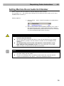
Setting Machine Room Audio Unit Number .......................................................................................... 72
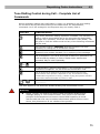
Tone Dialling Control during Call – Complete List of Commands ..................................................... 73
4.3
FIREMAN FUNCTION................................................................................................................................ 74
Description ................................................................................................................................................. 74
Use .............................................................................................................................................................. 74
Setting......................................................................................................................................................... 74
4.4
FUNCTION DESCRIPTION (FOR ADVANCED USERS) .............................................................................. 75
Purpose of Section ................................................................................................................................... 75
Outgoing Call ............................................................................................................................................. 75
Machine Room Call .................................................................................................................................. 75
Triphony ..................................................................................................................................................... 76
Checking Call ............................................................................................................................................ 76
Incoming Call ............................................................................................................................................. 76
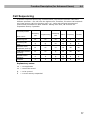
Call Sequencing ........................................................................................................................................ 77
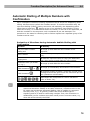
Automatic Dialling of Multiple Numbers with Confirmation ................................................................. 78
Automatic Redialling of Multiple Numbers without Confirmation ....................................................... 79
Automatic Call Receiving ......................................................................................................................... 79
Survey of Messages ................................................................................................................................. 80
Call End (Outgoing / Incoming Calls) ..................................................................................................... 80
5.
Use of Switches ........................................................................................................................................ 80
MAINTENANCE .......................................................................................... 83
5.1
BATTERY MAINTENANCE ........................................................................................................................ 84
Interruption of Operation .......................................................................................................................... 84
List of Battery Endangering Situations .................................................................................................. 84
Battery Pack Replacement ...................................................................................................................... 85
5.2
6.
FIRMWARE UPGRADE ............................................................................................................................. 86
Procedure................................................................................................................................................... 86
TECHNICAL PARAMETERS ........................................................................... 87
6.1
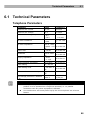
TECHNICAL PARAMETERS ...................................................................................................................... 88
Telephone Parameters ............................................................................................................................ 88
7.
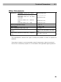
Other Parameters ..................................................................................................................................... 89
SUPPLEMENTARY INFORMATION .................................................................. 91
7.1
REGULATIONS ......................................................................................................................................... 92
7.2
TROUBLESHOOTING................................................................................................................................ 93
FAQ ............................................................................................................................................................. 93
7.3
LIST OF FIGURES .................................................................................................................................... 94
7.4
GENERAL INSTRUCTIONS AND CAUTIONS .............................................................................................. 95
Electric Waste and Used Battery Pack Handling ................................................................................. 96
1
1.
Product Overview
In this section, we introduce the 2N® LiftNet product, outline its application options
and highlight the advantages following from its use.
Here is what you can find in this section:
Product Description
2N® LiftNet Components and Associated Products
Changes
Terms and Symbols Used
7
Product Description
1.1
1.1 Product Description
Basic Features
Up to 8-lift connectivity
Lift cabin, shaft and machine room audio units
Minimisation of interconnecting wiring
Excellent acoustic features
In-built back-up battery pack
Easy control and programming – voice menu
Checking call function
Lift blocking option during connection failure
Internal communication – triphony
Telephone/PC-based programming
USB port
User message recording option
Local dispatching option (Intercom)
Fireman function
Basic Description
2N® LiftNet (LN) is a communication system similar to the intercom. The audio units
are connected (through a pair of conductors) to a common bus, to which one central
unit (CU) is connected. The CU controls the system operation and provides connection
to the dispatching office. Up to 32 audio units can be connected to the bus.
Each audio unit is uniquely identified: by lift number 1 to 8 and position: shaft bottom,
cabin interior, cabin roof and machine room. The machine room audio unit can be
shared by multiple lifts.
The CU is supplied with 12V DC. It contains an easily replaceable back-up accumulator
battery pack (4 AA Ni-MH cells in a holder). The CU is responsible for battery charging
and status monitoring. It indicates the charging status, telephone line status and
current communication by means of three colour LEDs. It is also equipped with a USB
port to provide comfortable parameter setting, voice message recording and software
upgrade.
8
Product Description
1.1
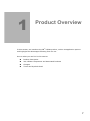
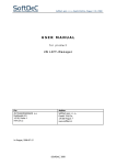
System Block Diagram
Figure 1.1 Example of Connection of PSTN CU and 3 2N® LiftNet Audio Units
9
Product Description
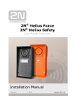
1.1
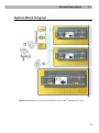
Figure 1.2 Example of CU and 2N® LiftNet Local Dispatching Audio Unit Connection
10
Product Description
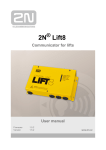
1.1
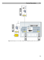
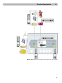
Figure 1.3 Example of Fireman Connection in 2N® LiftNet
11
2N® LiftNet Components and Associated Products
1.2
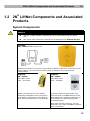
1.2 2N® LiftNet Components and Associated
Products
System Components
Caution
The 2N® LiftNet system components can be used within the LN system
only.
The audio units cannot be connected to a telephone line without the CU!
913600E
2N® LiftNet PSTN Central Unit
Enables to connect up to 8 lifts to an analogue PSTN or PBX line. Including a power
supply adapter and accumulator battery pack. A USB port for programming
configuration.
913610E
2N® LiftNet
913613E
2N® LiftNet
Lift Cabin Audio
Unit – Universal
Lift Cabin Audio
Unit – Compact
Audio unit electronics for lift cabins.
Including loudspeaker and microphone
(HandsFree). Necessary terminals and
door opening signal input (not optional).
A robust, metal-encased audio unit,
provided with an ALARM button of the
prescribed size, including indicators for
blind people and backlit pictograms
(hardened glass).
Easy wall surface mounting, 16-mm
thickness only. Easy installation (paired
wire connection).
12
2N® LiftNet Components and Associated Products
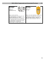
1.2
913611ESET
2N® LiftNet
913612E
2N® LiftNet
Audio unit –
machine
room/dispatching
Audio unit –
lift shaft
Audio unit for machine
rooms/dispatching, including siren and
standard telephone set. Helps
communicate with any audio unit in the
system and program the CU without a
PC. Equipped with a lift blocking contact
in case LN fails to call for help. Can be
programmed as a multiple-lift
communicator. A robust yellow cover.
Audio unit to be installed in the lift shaft
or upon the lift cabin roof. A robust
yellow cover. HandsFree mode, ALARM
and TRIPHONY buttons, indication
elements. Not intended for cabin use.
13
2N® LiftNet Components and Associated Products
1.2
Associated Products
913630E
2N® LiftManager
The 2N® LiftManager system is intended for remote monitoring, control and
communication with 2N® LiftNet, 2N® EasyTalk and 2N® SingleTalk units. Part of the
2N® LiftManager installation is Service Tool application which is aimed to manage
configurations of available devices (2N ® LiftNet units). 2N® LiftManager is intended
for use by companies (or individuals) who install or maintain lifts.
501300E
2N® EasyGate
501399E
2N® EnergyBank
GSM Solution for
2N® LiftNet and
2N® SingleTalk
Backup power
supply for GSM
gateway
PSTN line replacement.
Back-up power source in case of power
supply failure.
Simple installation without programming.
Simple installation.
14
Upgrade and Innovations
1.3
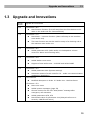
1.3 Upgrade and Innovations
Manual
version
Upgrade an innovations
1.8.0
In firmware 1.8.0
1.7.0
1.6.0
In firmware 1.7.0
New Alarm – intercom function (alarm call setup to the machine
room audio unit)
This new function can also be used for setup of a checking call to
the machine room audio unit
In firmware 1.6.0
1.5.8
1.5.5
1.5.2
New Fireman function (fire call setup from the Fire Station to the
cabin in the shaft with the lowest address)
Added parameter 932 (cabin audio unit loudspeaker volume
control for alarm and incoming calls)
In firmware 1.5.8
Added Italian voice menu
Support of new audio units - 913613E and 913613WBE
In firmware 1.5.5
Added parameter 990 (System settings)
Automatic restart of audio units for CU – audio unit communication
monitoring (WatchDog)
In the manual
Modified description in Subs. 2.5 Audio Unit - Machine Room
In firmware 1.5.2
New voice menu
Added system messages (page 59)
Shorter timeout for the first “Wait please” message after
emergency call activation
Added parameters 978, 979
New default value for parameter 914 (delayed call set to 0
seconds, CANCEL still active)
15
Terms and Symbols Used
1.4
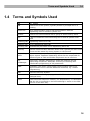
1.4 Terms and Symbols Used
LN
2N® LiftNet
CU
Central unit of the system, typically shared by multiple lifts in a
building
Audio unit
Voice communication unit for lift communication with the
dispatching office or another system unit
System
Central unit interconnected with a group of audio units by a bus
Bus
A pair of conductors interconnecting the CU and all system audio
units
Incoming call
dispatching office-to-CU call
Outgoing call
CU-to-dispatching office call
Checking call
Automatically activated CU-to-dispatching office call
Triphony
Internal communication between audio units, typically all audio units
of one and the same lift, during repairs or rescue work
Dispatching
office
Receives emergency calls, checking calls and, if necessary, lift
failure reports. Separate dispatching offices can be responsible for
different types of calls and mobile telephones can be used too.
LM,
Supervisory software designed for small and medium-size lift
supervising companies. Automatic receiving of checking calls.
Comfortable programming of CU parameters.
LiftManager
DISA
Automatic voice menu, which helps route incoming calls to the
required audio unit or activate additional functions, e.g. remote
programming
ESS
Electronic Security System
PBX
Private branch exchange (equipped with PSTN interface and local
analogue lines)
PSTN
Public switched telephone network. For simplification, it is assumed
that the CU is connected to the PSTN although it works on the PBX
line too in the same way.
16
Terms and Symbols Used
1.4
Symbols in Manual
Safety
Always abide by this information to prevent persons from injury.
Warning
Always abide by this information to prevent damage to the device.
Caution
Important information for system functionality.
Tip
Useful information for quick and efficient functionality.
Note
Routines or advice for efficient use of the device.
Future functions
The grey-marked text in this document designates the functions and features that are
under preparation or development at present.
17
2
2.
Description and
Installation
The section is divided according to system components into the following subsections:
PSTN Central Unit
Lift Cabin Audio Unit – Universal
Lift Cabin Audio Unit – Compact
Audio Unit – Machine Room
Audio Unit – Lift Shaft / Cabin Roof
LN Programming
Each subsection includes:
Component Description
Before You Start
Mounting
Electric Installation
19
PSTN Central Unit
2.1
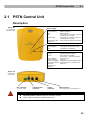
2.1 PSTN Central Unit
Description
Figure 2.1
Central Unit
LED Indicators
Power supply
Green
Green flashing
Red
Off
Red flashing
Red flashing after
power up
OK (battery full)
Battery charging
Battery failure
Power failure, more than 1 hour of
operating time remains
Power failure, less than 1 hour of
operating time remains
Audio unit FW upgrade proceeding
Telephone line
Green
Green flashing
Red
Line OK, ready (on-hook)
Line picked up (off=hook, call)
Line failure (no dialtone)
Communication
No light
Yellow
Green
Green flashing
Yellow flashing
Fast green flashing
Fast yellow flashing
Alternate
yellow/green
flashing
Relax (ALARM reset)
ALARM activated (calling)
Call confirmed (ALARM
announced) / Fireman activated
Incoming call
Triphony
Programming from dispatching office
Programming from machine room
Bus busy
Figure 2.2
Central Unit
Connectors
Bus connector
(to audio units)
Telephone line
connector
Supply
connector
USB connector
(for programming, upgrading etc.)
Warning
Do not open the CU during the warranty period.
Later, open for battery replacement only.
20
PSTN Central Unit
2.1
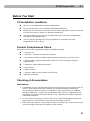
Before You Start
CU installation conditions
The CU is not designed for outdoor applications.
Do not mount the CU onto vibration-producing machines.
Install the CU vertically to allow air flow for cooling purposes (never cover the
CU with any cloth or install it in another closed box).
You may install the CU into the lift switching board unless the temperature
exceeds the acceptable limit.
The CU may be operated in the lying position on a desk at the room
temperature of up to 25 °C.
Product Completeness Check
Check the product for completeness before installation please:
1 central unit
1 terminal – inserted on the bus connector
1 accumulator battery isolation tape is present (sticking out of the cover)
1 power supply adapter conforming 12V DC to the local power network
requirements
1 telephone cable with RJ terminals
2 wall dowels
2 dowel screws
1 manual, either in the printed or CD format
warranty certificate
Checking of Accumulators
Instructions
1. Completely pull out the tape that sticks out of one opening on the back side of
the CU. This tape protects the inserted accumulators against discharging
during storage. With this tape it is possible to store the product (if supplied
including batteries) ½ year since the shipping date, which is indicated on the
packaging. After this period the claims, if any, regarding the battery warranty
cannot be accepted.
2. Do not connect anything to the CU and if any control lamps light up after the
tape has been removed wait a few seconds until they turn off.
3. Now watch the “power” control lamp on the CU carefully for a few seconds (not
in direct sunlight because the flashing is not strong):
21
PSTN Central Unit
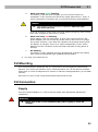
a.
2.1
Weak and short green flashing
The battery is OK and fully charged, you may continue with the
installation. If the product was stored for longer period than ½ year, or
under temperature exceeding 25 °C proceed according to paragraph b.
Caution
The product needs to be put in operation after the tape
has been removed.
It can be stored no longer than one week without charging; after having
been fully charged no more than 1 month.
b.
Weak and short red flashing
Some battery cells are discharged. In such case connect the 12V DC
power adapter (do not connect any audio units!) and let the CU charge
for at least 24 hours, even after the indicator has starting showing that
the battery is charged. This is a so-called compensatory cycle, which
balances out the condition of the individual cells after a long period of
storage.
c.
No flashing
The battery is fully depleted and may be damaged. Replace the battery
with a new recommended type (SANYO Eneloop 2000).
4. You may now install the CU.
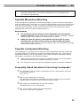
CU Mounting
It is recommended to install the CU in a room that is secured against unauthorised
persons, such as the lift machine room, switching station etc. On an easily accessible
place there is a risk of telephone line misuse or SIM card misappropriation (in the GSM
version).
Mount the CU onto a wall using the attached dowels and screws.
CU Connection
Supply
Use the included adapter or a 12V DC power supply with appropriate parameters
(stabilised).
Warning
Never use an AC or non-stabilised DC power supply to avoid CU
damage.
22
PSTN Central Unit
2.1
Bus Connection
Requirements
With multi-wire cables, always use a symmetrical twisted pair of conductors
(i.e. those that match each other). Standard UTP cables contain twisted pairs.
With special cabling (in the cabin), use the adjoining cables and make sure
that the nearest neighbouring conductors do not radiate interference (power
cables, video signals, etc.).
Recommendations
Do not lead the bus close to power cables, especially in long-distance
sections.
Branch the bus to shorten the total length of sections.
Safety
The bus is electrically isolated from the telephone line circuits according to
the EN60950 standard requirements and its low voltage cannot cause any
electrical accident.
CU Connection to Telephone Line
LN works in a wide range regardless of polarity and line parameters (refer to Technical
parameters). Connect it using the attached cable with an RJ-12 terminal.
Caution
One CU may be connected to one telephone line only and no other
telephone terminal equipment may be connected to this line.
2N® LiftNet requires the telephone line exclusively for itself. This means
that NOT even a system through which the telephone line goes (priority
connection, ESS, e.g.) may be connected to this telephone line.
No double or group serial lines may be used.
No telephone “multiplugs”, even the “intelligent” ones, may be used.
Never connect LN to an ISDN line.
CU telephone network connection options
There are four connection options:
PSTN line
PBX line
GSM gateway
VoIP adapter
23
PSTN Central Unit
2.1
Direct PSTN Connection
This is the simplest and most reliable type of connection. High operational costs (flat
rate costs) are a drawback of this solution.
Telephone line requirements
No double or group serial line.
The telephone socket including cabling is a property of the telecom company
and may not be tampered with.
Other recommendations
Notify the telephone network provider of your LN installation and submit
certification upon request.
Your follow-up cabling has to meet all applicable safety regulations.
You are recommended to secure your cabling physically against piracy (with a
telephone lock, e.g.).
PBX Connection
This is the least-cost solution where a PBX and an unused PBX line are available.
PBX line requirements
The PBX to be used must work reliably even in the case of power outage.
Large PBXs are mostly equipped with a back-up power supply, smaller PBXs
usually use PSTN line redirection in the event of power failure. Consult the
problem with the technician responsible for your PBX. An error during power
outage may result in LN calling an undesired station.
Relevant call access rights have to be assigned to the PBX line to be used (use
a standard telephone set to check whether the line can make calls to all
required „external”/CO line numbers).
While programming, enter all necessary PSTN prefixes (typically a zero), or
(which is a better solution) make the PBX not require a prefix (so-called
automatic CO line seizure).
To make dispatching office–lift calls, you have to know the extension number
and how to get through to it (dial-in, DISA, operator).
The dispatching office–lift connection may not depend on the operator’s
presence, no call redirection to a fax machine in the night mode is allowed,
etc.
Other recommendations
Make an agreement with the PBX owner regarding operating costs (LN outgoing calls
are billed at the owner‘s expense with the exception of free calls on “green lines”).
Tip
Where a non-stop security or porter’s service is available, the personnel
can be trained in rescue operations and LN can be programmed to call this
service.
24
PSTN Central Unit
2.1
GSM Gateway Connection (Temporary – Substitutes the GSM CU
Version, Part No. 501303E)
Used wherever no fixed telephone line is available.
Requirements
The GSM gateway has to be functional even in the case of power outage.
The GSM gateway has to recover its function without requiring the PIN.
Other requirements
Find a suitable place or use a special (directional) antenna where the GSM
signal quality is poor.
Secure the GSM gateway SIM card against misappropriation.
With a pre-paid SIM card, monitor the credit use and on-time replenishing.
VoIP Adapter Connection
This is the cheapest solution where a reliable Internet connection is available.
Requirements
The entire system has to be functional even in the case of power outage.
Other recommendations
As the VoIP technology is rather complicated, make sure that the dispatching
office personnel monitor connectivity reliably (evaluate the checking calls).
Tip
Some VoIP adapters have two independent telephone lines. A majority of
subscribers use just one line and the other line is thus available “free of
charge”.
Operation without Telephone Line
LN can be used as an intercom during lift assembly work even without a telephone
line. In that case, make sure that the lift blocking function is not activated until the
telephone line has been connected.
USB Port Connection
Recommendations
Do not leave a PC connected for a long time unless necessary in order to minimise risk
of PC damage due to HV shock from the telephone line during storms, e.g.
25
PSTN Central Unit
2.1
Interruption of Operation, Battery Maintenance
Caution
Never leave the batteries discharged for unnecessarily long periods.
If the battery is fully discharged please recharge it as soon as possible.
For a detailed description of situations that require your attention due to the state of
accumulators during interruption refer to the Maintenance section. Remember that
the state of accumulators is essential for system operation in any case. The
Maintenance section also contains instructions for accumulator maintenance, including
replacement.
26
Lift Cabin Audio Unit – Universal
2.2
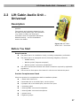
2.2 Lift Cabin Audio Unit –
Universal
Description
The user is not in a direct contact with this
product.
The controls and indicators depend on the
lift cabin control panel type. The indicators
(e.g. bulbs or LEDs) are working in
accordance with the applicable standards.
Address Setting – see the Installation
section for details.
Figure 2.3 Lift Cabin
Audio Unit – Universal
Before You Start
Requirements
The panel has to be installation-ready, including loudspeaker perforation.
The panel has to be equipped with the following obligatory elements:
o
ALARM button;
o
Backlit symbol “Request accepted”;
o
Backlit symbol “Connection established”.
The above mentioned elements have been located as required by applicable
regulations.
There must be free space of at least 65×130×20 mm behind the panel.
Product Completeness Check
Check the product for completeness before installation please:
1 board with electronics
4 terminals slid on the board pins, see the photo
4 jumpers slid on the board pins, see the cover print
1 mounting panel
1 directly/cable-connected loudspeaker
1 directly/cable-connected microphone
1 printed cover
5 tightening strips
27
Lift Cabin Audio Unit – Universal
2.2
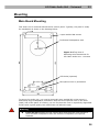
Mounting
Main Board Mounting
This audio unit is mounted behind the lift control panel. Typically, the panel is ready
for installation as shown in the drawing below:
4 spot-welded M4 screws
Perforated loudspeaker area
Figure 2.4 Top View of
Mounting Hole Dimensions for
Lift Cabin Audio Unit - Universa
LED holes (optional)
Microphone hole or perforation
To mount the audio unit, you need 4 electrically spot welded M3 or M4 screws, a
sufficiently large loudspeaker perforation area and a microphone hole on the inner
(back) side of the panel. If needed, you can fix the audio unit on a perfectly degreased
surface with a good-quality two-sided foam self-adhesive tape.
Warning
Leave no gap between the lift control panel and the audio unit surface to
avoid acoustic loudspeaker fault and acoustic loudspeaker-microphone
feedback.
28
Lift Cabin Audio Unit – Universal
2.2
Do not use this type of audio unit in a position other than mounted on a
sufficiently large board. The acoustic properties of an uninstalled audio
unit cannot be guaranteed.
Separate Microphone Mounting
If the microphone is separated (connected by cable) it has a 25×25 mm large board
with self-adhesive foil. This helps you mount it easily behind any hole in the panel (the
minimum hole diameter is 5 mm, or a group of smaller holes of the same total area).
Just glue the microphone directly onto the required place from behind (be sure to
degrease and clean the surface carefully before!).
Requirements
The minimum distance between the loudspeaker and microphone
centres is 90 mm. A lower distance may lead to acoustic feedback. A greater
distance (within the available 1m cable) does not matter.
Make sure that the glued-on microphone does not pick up (even
partially!) the acoustic pressure from the space behind the panel.
Such sensing might result in acoustic feedback since the loudspeaker strongly
radiates sound into the cavity.
Separate Loudspeaker Mounting
The loudspeaker is equipped with a cable and can be separated from the electronics
by simply sliding it out within the reach of the cables delivered (1m). This option is
useful where there is not enough space for the whole electronic equipment. Fit the
loudspeaker according to the instructions below:
While gluing choose such procedures or adhesives that prevent membrane
damage by adhesives and volatile substances, or heat.
We recommend you to keep the loudspeaker sealed to eliminate vibrations.
Frequently Asked Questions Concerning Loudspeaker
Is it possible to use a common loudspeaker for the communicator and floor
announcing machine?
No, it is not.
May I use a loudspeaker of my own?
Yes, but make sure that the impedance is 64 Ω. By doing this you assume
responsibility for sufficient volume and frequency range.
May I place the loudspeaker on the cabin ceiling?
This placement is not recommended.
May I use a longer cable with the loudspeaker?
Yes, but not with the microphone.
29
Lift Cabin Audio Unit – Universal
2.2
Electric Installation
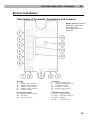
Description of Terminals, Connectors and Jumpers
Figure 2.5 Description of
Terminals, Connectors
and Jumpers for
Lift Cabin Audio Unit –
Universal
Terminals
1
Bus
2
ALARM, voltage activation
3
ALARM, contact activation
4
CANCEL, voltage activation
5
CANCEL, contact activation
6
indicator switches
Connectors
7
“Request accepted” LED
8
“Connection established” LED
9
Microphone connector
10
Loudspeaker connector
11
Induction loop connector
14
Service connector
Configuration jumpers
12
ALARM / CANCEL inversion
LED indicators (rear side):
1. (yellow) Request accepted
13
Lift number
2. (green)
Connection confirmed
15
Audio unit position
3. (yellow)
Triphony
4. (red)
Upgrade or error
30
Lift Cabin Audio Unit – Universal
2.2
Note
If external LEDs are connected to connectors 7 and 8, on-board LEDs 1
and 2 will not be shining.
Address Setting
The audio unit address means setting of two jumpers,
namely the lift number (1 to 8) and audio unit position
(refer to the cover drawing). If you install the audio unit
in the cabin of lift 1, you need not change the jumper
configuration. In other cases, follow the instructions
below:
Instructions
1. Release slightly the three screws on the
electronics cover.
2. Slide the cover to the right to expose the
jumpers.
3. Set the required changes as shown on the
electronics cover.
4. Replace the cover and tighten the screws.
Figure 2.6 Address Setting for Lift Cabin
Audio Unit – Universal
Notes
Make sure that two audio units do not have an identical address to avoid
system error.
The position-setting jumpers are employed exceptionally, e.g. where a
certain audio unit type is used in a position other than normal.
To recover the initial address setting, follow the drawing on the cover.
Bus Connection
The connection polarity is arbitrary.
Warning
Connection to different, e.g. higher-voltage, cables leads to damage or
destruction of the audio unit.
Caution
The unit is powered via a 2-wire bus from the central unit. Unplugging of
the bus from the CU causes switching off of the unit.
Avoid the audio unit address duplicity.
31
Lift Cabin Audio Unit – Universal
2.2
ALARM Button Connection
Requirements
The ALARM button design (colour, symbol, button surface, mechanical run) and
location have to meet the requirements of the particular installation.
Button control
Requirements
The ALARM button has to be equipped with a normally open (NO) or normally
closed (NC) contact that is not connected with any other circuit.
None of the ALARM button terminals may be connected electrically with any
other electrical circuit and a voltage source other than the NO/NC contact.
If one of the ALARM contacts is connected to another circuit, appropriate
isolation strength according to applicable standards has to be ensured
between the contacts.
Instructions
1. Leave the ALARM terminal in the LOW position (3).
2. With a normally closed contact, leave jumper (12) – right in the default
position.
3. With a normally open contact, switch jumper (12) – right into the HIGH
position.
Voltage control
Requirements
DC 12 to 48V voltage
The voltage signal has to be active even in the case of power failure.
Instructions
1. Switch the ALARM terminal by two pins up into position (2).
2. For activation by voltage connection, leave jumper (12) – right in the default
position.
3. For activation by voltage disconnection, switch jumper (12) – right into the
HIGH position.
Caution
Jumper setting, as printed on the unit cover of pre-production samples, is
only valid for CANCEL and wrong for ALARM.
See above for the proper setting.
Warning
Ignoring the instructions above may lead to product damage.
32
Lift Cabin Audio Unit – Universal
2.2
CANCEL Input Connection (Door Contact, Optional)
This input helps cancel a rescue request if the lift is fully functional. When the ALARM
button is pressed, the system waits for a pre-programmed period of time, which is a
little longer than the maximum lift running time. If the lift is functional, it arrives in
the required station within this timeout and opens the door. In that case, the rescue
request is cancelled. If the door fails to open, the request is accepted.
Find out before installation whether the door opening signal is available in the lift
cabin.
Requirements
In double-door lifts, the signal has to be active only if both the doors open successfully
and let the people out.
The door position signal has to work even in the case of power outage.
Contact control
Requirements
None of the CANCEL terminals may be connected electrically with any other
electrical circuit and a voltage source other than the contact.
Instructions
1. Keep the CANCEL terminal in the LOW position (5).
2. With a normally open contact, leave jumper (12) – left in the default position.
3. With a normally closed contact, switch jumper (12) – left into the LOW
position.
Voltage control
Requirements
DC 12 to 48V voltage
Instructions
1. Switch the CANCEL terminal by two pins up into position (4).
2. For activation by voltage connection, leave jumper (12) – left in the default
position.
3. For activation by voltage disconnection, switch jumper (12) – left into the LOW
position.
Warning
Ignoring the instructions above may lead to product damage.
Note
Remember to program delayed calling to make the CANCEL connection
work successfully.
33
Lift Cabin Audio Unit – Universal
2.2
Indicator Connection
The basic configuration providing (using an external source) a sufficient illumination
intensity of indication elements is shown in the figure:
Figure 2.7 Basic
Indicator Connection for
Lift Cabin Audio Unit –
Universal
Requirements
The DC power supply has to be backed-up.
Notes
LN continues working except for the indicators during power outage.
The indication elements (bulbs, e.g.) may have the maximum current of
200 mA each.
Mind polarity in this case.
Alternative indicator connection (LED)
Today’s LED producing technologies help achieve a relatively good illumination
intensity at a low current supply. If a 5 mA LED (with diode loss of approx. 2V) is able
to provide efficient illumination in the lift, no power supply is needed. For this
configuration see
the figure below:
Figure 2.8 Alternative
Indicator Connection for Lift
Cabin Audio Unit – Universal
Notes
The cables required for this configuration are not part of the standard
delivery but are available upon agreement.
In this configuration, the auxiliary indicators on the PCB are not shining.
34
Lift Cabin Audio Unit – Universal
2.2
Induction Loop Connection
The regulations that apply to communicator installations may require a mandatory
loop for persons with defective hearing in the lift cabin. In that case, connect the loop
to connector (10) with any polarity. The loop including a 1m long cable can be part of
your delivery if agreed.
Requirements
The induction loop has to be placed behind a non-metal, non-magnetic cover
in the control panel because the magnetic field of the induction loop cannot go
through the metal control panel.
The induction loop has to be labelled with an appropriate symbol (ear) placed
according to applicable standards.
35
Lift Cabin Audio Unit – Compact
2.3
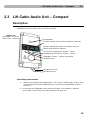
2.3 Lift Cabin Audio Unit – Compact
Description
This audio unit is designed for lift wall mounting. No opening has to be cut for
installation since the audio unit is surface mounted.
Figure 2.9
Description of Lift bin
Audio Unit – Compact
Loudspeaker
Symbol window (also access to address switches)
Symbol indicating location of induction loop for
people with defective hearing
“Connection established” symbol – green
“Establishing connection” symbol – yellow
TRIPHONY symbol – yellow if activated
ALARM button
Window bezel hole
Microphone hole
Operating instructions
1.
Activate by pressing the ALARM button. The “Wait” symbol lights up and, once
communication has been established, the “Connection established” symbol
comes on.
2. To activate the TRIPHONY mode press the button on the shaft or machine
room audio unit for which the same address has been set.
36
Lift Cabin Audio Unit – Compact
2.3
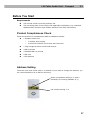
Before You Start
Requirements
The lift wall surface must be perfectly flat.
The mounting place must comply with applicable regulations (e.g. standard
ALARM button elevation and relative distance from other lift buttons).
Product Completeness Check
Check the product for completeness before installation please:
1 Compact audio unit
o
1 window with printing
o
2 terminals inserted in the back side connector
1 long hexagonal 2mm round-head wrench
4 M4×8 screws
4 headless M4×30 screws
4 M4 nuts
4 fan washers
Address Setting
The audio unit is set as lift cabin 1 by default. If you want to change the address, you
are recommended to do so before mounting.
Audio unit position setting 0–3 with a
possibility of inverting CANCEL (4–7)
Lift number setting 1–8
37
Lift Cabin Audio Unit – Compact
2.3
Instructions
1. Insert the hex wrench (included in the delivery) in
the bottom unit edge hole; turn left about 10 times
until it puts up resistance.
2. The window slides down by itself or with little
assistance, showing its upper brim.
3. Tilt the window forwards and remove.
4. Set the audio unit address using a screw driver:
left rotary switch:
right rotary switch:
0 or 4 … machine room
1–8 = lift number
1 or 5 … shaft bottom
2 or 6 … lift cabin
3 or 7 … lift cabin
ceiling
Caution
Right rotary switch: 1 to 8 print, i.e.
set 1 for lift number 2 etc.
Note
Left rotary switch: If you use the
CANCEL input and the contact is open
with the door closed, set the left switch
into one of positions 0 to 3; if the
contact is closed with the door closed,
set the left switch into one of positions
4 to 7.
5. Replace the window.
Figure 2.10 Address Setting for
Lift Cabin Audio Unit – Compact
6. Insert the hex wrench (included in the delivery) in
the bottom unit edge hole, turn right about 10 times
until the window slides under the panel edge and
tighten applying light force.
38
Lift Cabin Audio Unit – Compact
2.3
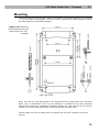
Mounting
Just drill holes into the lift cabin wall as indicated in the drawing below or as printed
1:1 on the audio unit package. The larger hole is intended for cable passage. Round
the hole edges to avoid cable damage!
Figure 2.11 Mounting
Hole Dimensions for Lift
Cabin Audio Unit Top Compact
Note: The two 2.5 mm large holes in the window area are used where the mounting
panel rear is inaccessible. The 2.5 mm diameter is suitable for all wall mounting
options using plywood, chipboard, laminated plastic etc. with the aid of the screws
included. For front metal panel wall mounting drill M4 threaded holes.
Further steps can only be made after connection and are thus included in the next
section.
39
Lift Cabin Audio Unit – Compact
2.3
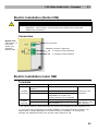
Electric Installation (Earlier HW)
Caution
Be sure to connect the wires before wall mounting. The connectors are
separable – remove them, connect the wires, tighten the screws and
replace the connectors.
Connectors
Figure 2.12
Connectors of
Lift Cabin
Audio Unit –
Compact
(Earlier HW)
Bus connector
CANCEL connector (optional)
in contact-control position
in voltage-control position
Electric Installation (Later HW)
Terminals
Telephone line / LN bus
DC = voltage
control *)
ALARM
N.O. = N/O contact
terminals N.C. = N/C contact
CANCEL
terminal
voltage control *)
contact control
Refer to ST or LN User Manual
5 – 24Vdc, any polarity
Normally open contact
Normally closed contact
WARNING! If unused, the
contact should not be opened!
5 – 24Vdc, any polarity **)
any contact **)
Emergency call
activation
Emergency call
deactivation upon
door opening
*) For safety reasons, these terminals are electrically isolated from the telephone line.
**) You need not do anything to activate ALARM if you keep the factory settings. For
deactivation, voltage application or contact closing is necessary. To change the
settings use parameter 916 for ST and the rotary switch for LN.
40
Lift Cabin Audio Unit – Compact
2.3
Connectors
Figure 2.13 Connectors of
Lift Cabin Audio Unit –
Compact (Later HW)
Warning
Make sure that the button is safe, i.e. that the minimum isolation distance
is 1.5 mm and the minimum breakdown voltage value is 1,500 V. The
button contacts may not be connected to any other circuits. If any of the
above conditions cannot be met, use voltage control.
You can use an N/O or N/C button or both.
Refer to the rear cover for internally connected terminals – see Fig. 2.13.
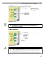
ALARM Button Connection with N/O Contact
Figure 2.14 ALARM
Button Connection with
N/O Contact
41
Lift Cabin Audio Unit – Compact
2.3
ALARM Button Connection with N/C Contact
Figure 2.15 ALARM
Button Connection with
N/C Contact
Note
The ALARM button mounted on the cover is still functional when an
external button is connected.
Voltage Activation
Figure 2.16 Voltage Activation
Caution
5 - 24 dc voltage of any polarity can be used. Make sure that the power
supply is backed up properly.
Where activation from multiple places is necessary, voltage control can be
combined with buttons.
A buzzer or horn can be connected in parallel, see the figure to the right.
42
Lift Cabin Audio Unit – Compact
2.3
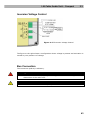
Inversion Voltage Control
Figure 2.17 Inversion Voltage Control
The figure to the right shows a configuration where voltage is present and activation is
caused by non-presence of voltage.
Bus Connection
The connection polarity is arbitrary.
Warning
Connection to different, e.g. higher-voltage, cables leads to damage or
destruction of the audio unit.
Caution
Avoid the audio unit address duplicity.
43
Lift Cabin Audio Unit – Compact
2.3
CANCEL Input Connection (Door Contact, Optional)
This input helps cancel a rescue request if the lift is fully functional. When the ALARM
button is pressed, the system waits for a pre-programmed period of time, which is a
little longer than the maximum lift running time. If the lift is functional, it arrives in
the required station within this timeout and opens the door. In that case, the rescue
request is cancelled. If the door fails to open, the request is accepted.
Make sure before installation that the “door open” signal is available in the lift cabin.
Requirements
In double-door lifts, the signal has to be active only if both the doors open
successfully and let the people out.
The door position signal has to work even in the case of power outage.
Contact control
Requirements
None of the CANCEL terminals may be connected electrically with any other
electrical circuit and a voltage source other than the contact.
Instructions
1. Connect the CANCEL terminal into upper position.
2. Make sure that the switch position matches the door contact configuration
(open or closed when the door is closed) – see Address setting.
Voltage control
Requirements
DC 12 to 48V voltage
Instructions
1. Connect the CANCEL terminal into lower position.
2. Make sure that the switch matches voltage presence or absence when the door
is closed – see Address Setting. Voltage presence corresponds to a closed
contact; voltage absence means an open contact.
Warning
Ignoring the instructions above may lead to product damage.
Note
Remember to program delayed calling to make the CANCEL connection
work successfully.
44
Lift Cabin Audio Unit – Compact
2.3
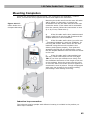
Mounting Completion
Connect the wires before wall mounting. The connectors are separable – remove
them, connect the wires, tighten the screws and replace the connectors.
Figure 2.18 Lift
Cabin Audio Unit –
Compact Mounting
Mounting the audio unit from the outer lift cabin
wall is easier. In that case, no screws are
accessible from the lift cabin and the audio unit
cannot be stolen. If the cabin wall is accessible
from the outside, follow the instructions in item
a) or b). If not, follow item c).
a)
If the lift cabin wall is thin (stainless steel
sheet), seek four 8 mm long M4 screws and fanshaped washers in the accessories.
b)
If the lift cabin wall is thick (up to 20 mm
– laminated chipboard), seek four headless, 30
mm long M4 screws. Screw them into the unit
backside using the wrench included in the
delivery and tighten properly. Then push the
assembly through the pre-drilled holes, insert
the fan-shaped washers from the back and screw
in the nuts.
c)
If the lift cabin wall is inaccessible from
the rear, follow instructions on the next page.
TIP: If you have pre-drilled corner holes, find
four headless M4 screws of the length of 30 mm
in the package. Drive the screws into the holes
on the rear side of the audio unit and tighten as
mentioned in item b) above. Though unequipped
with nuts, the screws fix the product reliably,
preventing it from sliding or turning.
Induction loop connection
The induction loop for people with defective hearing is included in the product, no
other loop is needed.
45
Lift Cabin Audio Unit – Compact
2.3
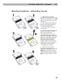
Mounting Completion – without Rear Access
1. Insert the hex wrench
(included in the delivery) in the
bottom unit edge hole; turn left
about 10 times until it puts up
resistance.
2. The window slides down by
itself or with little assistance,
showing its upper brim.
3. Tilt the window forwards
and remove.
4. Now you have access to two
holes in the window corners.
Put unit (including the
connected wires) on the predrilled lift cabin wall. Drive and
tighten the included screws for
plywood, chipboard, laminated
plastic etc. wall mounting or
short M4 screws with fanshaped washers (intended for
metal plate mounting with predrilled M4 threaded holes).
5. Replace the window.
6. Insert the hex wrench
(included in the delivery) in the
bottom unit edge hole, turn
right about 10 times until the
window slides under the panel
edge and tighten applying light
force.
46
Audio Unit – Machine Room
2.4
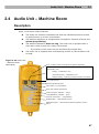
2.4 Audio Unit – Machine Room
Description
This audio unit is designed for machine room installation. Compared with the other
types, it has some unique features:
The audio unit contains a telephone set with the HandsFree/receiver modes
for good function in a noisy environment.
The attached telephone is equipped with a keypad for function selection and
system programming.
The attached telephone does not ring. The audio unit is equipped with a
siren that is loud enough for a noisy environment.
o
Figure 2.19 Audio Unit
– Machine Room
Description
The machine room audio unit can be shared by multiple lifts.
The audio unit is equipped with a lift blocking contact in case LN fails to call
for help.
siren – beeps to alert incoming call or triphony beginning
LED indicator (red)
shining – initialisation (10s)
constantly shining – initialisation error
brightly shining – light bell (together with the siren beep)
Door locking screw
Address adjustment doors
Lift number (1–8) adjustment
Audio unit position adjustment
“Call in progress” indicator – yellow
“Call established” indicator – green
“Fireman connection” – green flashing
ALARM button – white-backlit at relax
TRIPHONY button – yellow-backlit when the triphony mode is
active
47
Audio Unit – Machine Room
2.4
Operating instructions
This unit may only be used by authorised persons such as the lift maintenance staff.
The TRIPHONY button activates voice communication between all units with the same
lift number.
The ALARM button can be used for calls to the dispatching centre. The ALARM button
backlight (not required by standards) allows you to find the unit in a dark
environment.
In both cases, it is necessary to pick up the attached phone.
If the attached phone is picked up and neither ALARM nor TRIPHONY is pressed, you
can make use of other functions; refer to the machine room voice menu.
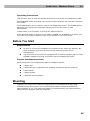
Before You Start
Requirements
Be sure to connect the telephone set included in the audio unit delivery. No
other telephone type may be used except with the consent of the
manufacturer.
The lift control circuit must be equipped with a function blocking input in case
the LN is unable to provide connection with the dispatching centre.
Product completeness check
Check the product for completeness before installation please:
1 audio unit
1 telephone set (a separate unit including accessories and the manual)
2 wall dowels
2 dowel screws
7 address setting jumpers
Mounting
Typically, the audio unit including a telephone set is mounted onto a wall using
available dowels and screws. The recommended machine-telephone distance is
approximately 10 cm. The maximum distance is determined by the interconnecting
cable delivered together with the telephone.
48
Audio Unit – Machine Room
2.4
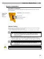
Electric Installation
Description of connectors
Release the screw on the right-hand side and open the connector cover. There are
three connectors:
Connectors (under the side door)
Figure 2.20
Audio Unit –
Machine
Room
Connectors
Bus connector
Lift blocking connector
Phone connector
Address Setting
There two groups of jumpers under the transparent front cover. For their meanings
see the printing located directly under them.
Left-hand group of 4 jumpers: leave them in the “machine room” position.
Note
You can set another position too – if, for example, you want to
have a classic telephone and thus program the CU on the shaft
bottom, you can use this audio unit and set the jumper into the
appropriate position.
Right-hand group of 8 jumpers: address setting. If the machine room is
shared by multiple lifts, you can use one audio unit and set more addresses
with the available jumpers. This is impossible with other types of audio units!
Note
If more addresses have been set in the audio unit, press the
TRIPHONY button to activate communication with the lift with the
lowest address.
Caution
Avoid the audio unit address duplicity.
49
Audio Unit – Machine Room
2.4
Bus Connection
Remove the terminal board from the connector, connect the wires and replace the
terminal board. The connection polarity is arbitrary.
Warning
Connection to different, e.g. higher-voltage, cables leads to damage or
destruction of the audio unit.
Caution
The unit is powered via a 2-wire bus from the central unit. Unplugging of
the bus from the CU causes switching off of the unit.
Telephone Connection
Use the telephone set including the cable with telephone terminals that are part of the
audio unit delivery.
Caution
The audio unit is not functional without a telephone set connected.
Connecting a telephone set of different type may result in difficulties, such
as system failure.
Testing
To test the function, pick up the handset. If no other call is currently being made, you
can hear the machine room voice menu.
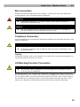
Lift Blocking Function Connection
Caution
This function may be mandatory if the local applicable regulations require
so at the time of installation.
Blocking procedure: the contact opens whenever a telephone line fault is detected or
the LN batteries are low. Connect the contact to the appropriate controller input of the
lift or a group of lifts. The control electronics shall ensure that, upon contact opening,
the lifts that are in operation arrive in the nearest station and open the door. If the
audio unit is shared by multiple lifts, all lifts must stop the function identically.
50
Audio Unit – Lift Shaft / Cabin Roof
2.5
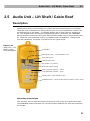
2.5 Audio Unit – Lift Shaft / Cabin Roof
Description
This audio unit is designed for installation on the lift shaft bottom or lift cabin roof, or
similar places where communication is needed during lift maintenance, for example.
The audio unit is enclosed in a robust yellow cover. It is not intended for outdoor use
but perfectly fits in lift shafts – is resistant against fall of small objects, dripping oil,
etc. The ALARM button activates the dispatching centre connection, the TRIPHONY
bottom enables conference connection with the other audio units of one and the same
lift. The audio unit contains a built-in microphone and a loudspeaker. Thanks to its
size and robustness, the audio unit features a very good sound.
Figure 2.21
Audio Unit – Lift
Shaft / Cabin
Roof Description
Loudspeaker
LED indicator (red) – unit initialisation error
Door locking screw
Address setting door
Lift number (1–8) setting
Audio unit position setting
“Call in progress” indicator – yellow
“Call established” indicator – green
ALARM button – white-backlit at relax
TRIPHONY button – yellow-backlit when the triphony mode is active
Operating instructions
This unit may only be used by authorised persons such as the lift maintenance staff.
The TRIPHONY button activates voice communication between all units with the same
lift number.
51
Audio Unit – Lift Shaft / Cabin Roof
2.5
The ALARM button can be used, for example, when somebody falls into the shaft. The
ALARM button backlight (not required by standards) allows you to find the unit in a
dark environment.
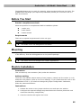
Before You Start
Product completeness check
Check the product for completeness before installation please:
1 audio unit
2 wall dowels
2 dowel screws
Requirements
There are no special requirements for this unit type.
Caution
This audio unit is not designed for lift cabins.
Mounting
Typically, the audio unit is mounted onto a wall using the dowels and screws included
in the delivery. Find the drilling pattern on the product package.
Caution
The audio unit is not designed for outdoor applications.
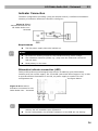
Electric Installation
Connectors
This unit has only one connector (bus) under the side door.
Address setting
The audio unit address means setting of two jumpers, namely the lift number (1 to 8)
and audio unit position (refer to the cover drawing). If you install the audio unit on the
shaft bottom of lift 1, you need not change the jumper configuration. Otherwise,
follow the instructions below:
Instructions
1. Release the screw on the jumper window cover and open the window.
2. Configure the required changes as printed below the window (this audio unit
cannot be shared by multiple lifts).
3. Close the window and tighten the screw.
52
Audio Unit – Lift Shaft / Cabin Roof
2.5
Warning
Avoid the audio unit address duplicity.
Connection
Release the screw on the right-hand side and open the connector cover. There is just
one connector – for bus connection. Remove the terminal board from the connector,
connect the wires and replace the terminal board. The connection polarity is arbitrary.
Warning
Connection to different, e.g. higher-voltage, cables leads to damage or
destruction of the audio unit.
Caution
The unit is powered via a 2-wire bus from the central unit. Unplugging of
the bus from the CU causes switching off of the unit.
53
3
3.
Configuration
This section describes programming of 2N® LiftNet. It is possible to program 2N®
LiftNet in three ways.
PSTN Line Programming
Machine Room Telephone Programming
PC Programming
55
LN Programming
3.1
3.1 LN Programming
The advantage is that it is only the CU that has to be programmed. Thus, it is
unnecessary to re-program the parameters after audio unit replacement. With a
multiple-lift system, you just program one CU. The memory is independent of the CU
power supply.
To program the CU choose one of the following three ways:
1. Remote (PSTN) telephone The access is password-protected. The voice menu is
programming
in the national language.
2. Machine room telephone
programming
3. PC USB programming
Use 2N® LiftManager including the Service Tools.
Also, you can use the firmware upgrade, download of
language mutations and user-recorded message.
PSTN Programming
Before You Start
Make sure that your telephone enables tone dialling (troubles may occur with
the so-called system/key telephones in some PBX systems).
Prepare a list of all parameters to be programmed in advance.
Make sure that, if LN is not entirely new, the service password is correct and,
if you are not quite sure of your LN configuration, execute full initialisation.
Caution
Remember to initialise the service password too!
Entering Programming Mode
You can enter the programming mode only during an incoming call (PSTN call to LN)
or upon line seizure by the machine room telephone.
To enable the programming mode press
service password in the format
to enter services and after that enter the
service password
.
Note
Remember to enter an asterisk before and after the password!
If the password is correct, LN reports “You have entered the programming menu” and
displays a context-dependent help. The default password is 12345 and you have a 5second timeout by default (or a user-defined limit of 1 to 9 seconds) to enter every
character of your password. If you fail to keep the timeout, LN hangs-up.
56
LN Programming
3.1
Note
You are recommended to change it to secure your equipment against
unauthorised access.
If you forget your password, contact the manufacturer to recover your
data.
Programming Procedure
Having entered the programming mode, you can change any programmable value(s)
in any order. Proceed as follows: enter the function number and then the value. Use
an asterisk as a separator or Enter. In general, the function has the following format:
function number
value
The function number has three digits (see the table). After you enter the function
number and an asterisk, LN reports the number or name, current value and potential
range of the parameter to be programmed. After you enter the value and another
asterisk, LN reports “Value stored”, or “Invalid value” if the value is beyond the
allowed range.
Warning
A drawback of some telephone sets is that, after you press a button, i.e.
send a DTMF signal, they go “deaf” for a fraction of a second. In that case,
you cannot hear the whole text and are recommended to use another
telephone.
Programming Error
If you make a mistake during entering (the function number or value) and have not
entered an asterisk yet, you can cancel the whole number by pressing
the digits.
and re-enter
If LN rejects a parameter number or value you have entered, go on programming but
re-enter the function number even if it was the value not the number that was wrong.
If you have programmed and stored a value other than you intended to, you can reenter the value of course.
Programming End
Having stored all values to be changed, terminate programming by pressing
. LN
sends a hang-up signal and hangs up. If you do not use the
character, LN hangs up
later without affecting the stored values (the values are stored immediately after
being entered).
If you are not quite sure of LN’s programming behaviour, save the filled-in form for
later check.
Troubleshooting
LN fails to respond correctly to DTMF commands, e.g. the programming mode cannot
be entered.
57
LN Programming
3.1
Today, voice transmission is prevailingly digital, using variable compression
algorithms. Therefore, the DTMF signal to be transmitted is often distorted. Moreover,
it may, in some cases, be transmitted through the so-called command channel, whose
delay may differ from that of the speech channel.
Caution
Experience shows that, especially recently, it is practically impossible to
recover the DTMF signal in GSM networks
In such cases, try some other equipment (a digital PBX, e.g.) or the machine room
telephone set. If the machine room or PSTN programming attempts fail too, you have
probably entered an invalid password.
58
Parameter Chart (FW v. 1.8.0)
3.2
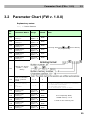
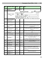
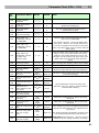
3.2 Parameter Chart (FW v. 1.8.0)
Explanatory notes:
Grey
Par.
No.
= future features
Parameter Name
Range
011
ALARM button
memory 1
up to 16
digits 0 - 9
blank
012
ALARM button
memory 2
up to 16
digits 0 - 9
blank
013
ALARM button
memory 3
up to 16
digits 0 - 9
blank
014
ALARM button
memory 4
up to 16
digits 0 - 9
blank
015
ALARM button
memory 5
up to 16
digits 0 - 9
blank
016
ALARM button
memory 6
up to 16
digits 0 - 9
blank
0-9
3
017
Default
Note
Entering characters
and
will be able by
PC programming.
Adding of a special
symbol *, # and
“delay”
018
Count of automatic
dialling cycles for
ALARM
019
Automatic dialling
type
for ALARM
071
0-3
1
Checking call
memory 1
up to 16
digits 0 - 9
blank
072
Checking call
memory 2
up to 16
digits 0 - 9
blank
073
Checking call
memory 3
up to 16
digits 0 - 9
blank
074
Checking call
memory 4
up to 16
digits 0 - 9
blank
075
Checking call
memory 5
up to 16
digits 0 - 9
blank
0
1
2
3
=
=
=
=
off (1 number from memory 1 is dialled)
with DTMF confirmation
with GSM confirmation
no confirmation (count of rings)
If let completely blank,
ALARM memory 1 to 6
is used for the checking call.
59
Parameter Chart (FW v. 1.8.0)
Par.
No.
076
077
Parameter Name
Range
Default
Checking call
memory 6
up to 16
digits 0 - 9
blank
3.2
Note
Adding of a special
symbol *, # and
“delay”
078
Count of automatic
dialling cycles for
checking call
0-9
3
079
Automatic dialling
type
for checking call
0-3
1
see parameter 019
906
Delay after digit
dialling
cannot be
changed
100ms
The parameter cannot be changed. It gives the
delay between the digit dialling and voice
message start.
909
Timeout for dialling
tone detection
1000 –
9999 ms
5000 ms
LN waits for the dialling or continuous tone for
this period of time. If it fails, the line is
defective.
911
Count of rings before
incoming call
answering
1-9
2
Defines the moment of picking up (for incoming
calls).
912
Max. call duration
10 – 1000
s
120 s
Call can be prolonged by command.
LN waits for confirmation for this period of time
(outgoing call, automatic dialling with come
confirmation enabled).
Timeout for call
confirmation
10 – 1000
s
60 s
914
Delayed call
0 – 1000 s
0s
915
Max. TRIPHONY
duration
10 – 9999
s
7200 s
917
On-hook time
between calls
500 –
9999 ms
5000 ms
913
918
Max. time of
telephone line test
920
921
If it fails, LN hangs sup and proceeds to the
next number. Measured from the dialling end.
1 – 20 s
5s
Call confirmation
command
cannot be
changed
1
Message muting
command
cannot be
changed
2
Applicable only if the CANCEL input is used
(913610E unit only).
A line test (dialtone test) is made every 11
minutes. If the dialtone is missing in three
subsequent tests, the lift gets blocked. When
the line is recovered, the lift gets unblocked
automatically.
Mutes the message too.
60
Parameter Chart (FW v. 1.8.0)
Par.
No.
Parameter Name
Range
922
Repeat message
command
cannot be
changed
3
923
DTMF identification
command
cannot be
changed
6
Mutes the message too.
924
Call prolongation
command
cannot be
changed
4
The call is prolonged by the time set in
parameter 912 again.
925
Call end command
cannot be
changed
5
930
Shaft audio unit
loudspeaker volume
for TRIPHONY
1 - 10
10
931
Cabin audio unit
loudspeaker volume
for TRIPHONY
1 - 20
932
Cabin audio unit
loudspeaker volume
for alarm and
incoming calls
1 - 20
10
Used for alarm and incoming calls. The volume
range is 1-20 for all cabin audio units (931).
However, the actual maximum is 10 for the
Compact unit and earlier HW cabin units (new
cabin audio units are louder than the older
types).
933
Receiving volume
1 - 10
10
For incoming and outgoing calls from/to PSTN.
934
Transmitting volume
1 - 10
10
For incoming and outgoing calls from/to PSTN.
940
Minimum dialling
tone time
200 –
2000 ms
400 ms
Must be longer than the busy tone duration!
941
Minimum continuous
tone time
200 –
9999 ms
2000 ms
LN hangs up if the continuous tone is detected
(not before dialling).
942
Minimum busy tone
period
100 – 500
ms
200 ms
943
Maximum busy tone
period
200 –
1600 ms
800 ms
944
Maximum tone –
space difference (for
busy tone)
10 – 400
ms
50 ms
945
Minimum count of
busy tone periods
2 - 50
5
946
First dual tone
frequency
300700Hz
370Hz
Parameter modification for British dual tone
detection.
947
Second dual tone
frequency
300700Hz
440Hz
Parameter modification for British dual tone
detection.
951
Minimum ringing tone 50 – 2000
time
ms
952
Minimum long space
time (for ringing
tone)
100 –
5000
Maximum long space
time (for ringing
500 –
9999
953
Default
3.2
10
Note
Used for echo cancelling between the audio
units if any in TRIPHONY.
The volume range is 1-20 for all cabin audio
units (931). However, the actual maximum is
10 for the Compact unit and earlier HW cabin
units (new cabin audio units are louder than the
older types).
These parameters control the busy tone
detection. They are used for call termination
and automatic dialling.
500 ms
The ringing tone time is integrated across the
ringing tone parts that are not separated by a
long delay.
1000 ms
The longest ringing period delay must be in the
interval between parameters 952 and 953.
ms
6000 ms
CAUTION! Parameters 951 – 953 are used (by
default now) for ringing detection (incoming
61
Parameter Chart (FW v. 1.8.0)
Par.
No.
Parameter Name
tone)
Range
Default
3.2
Note
calls).
ms
961
Maximum timeout for
pressing the next
digit
1 – 100 s
10 s
During password entering, programming, etc.
962
Minimum time of
pressing ALARM, for
cabin units
10 – 9999
ms
100 ms
A short time set temporarily for easier testing.
963
Minimum time of
pressing ALARM, for
other units
10 – 9999
ms
100 ms
964
Minimum active
CANCEL input time
10 – 9999
ms
100 ms
Temporarily a single tone, 1 s long.
968
Machine room
alerting tone (siren)
970
Identification type for
ALARM calls
1-2
0
973
Language for numeric
messages
0-1
1
974
Lift identification
1 – 60 s
1s
There is a future possibility to start alerting the
moment an incoming ringing is detected. When
the call is answered in the machine room, the
voice menu will be cancelled.
1: LN identification on (incl. audio Id)
up to 16
digits 0 - 9
blank
2: LN identification equal to ST identification
(without parameter YY – audio unit Id)
0 = User recorded
1 = English
The number enables lift identification for
foreigners, for example. Also used for automatic
®
call handling (2N LiftManager). If blank, the
serial number is reported.
It allows playing back messages in more
languages in the defined sequence, including
the identification number, etc.
975
Local message
sequence
Up to 8
messages
(each has
2-digit ID)
976
Outgoing message
sequence
Up to 8
messages
(each has
2-digit ID)
blank
(=22)
blank
(=2324)
01
02
03
04
05
06
07
08
09
10
11
12
13
14
15
16
17
18
19
20
21
=
=
=
=
=
=
=
=
=
=
=
=
=
=
=
=
=
=
=
=
=
User message #1
User message #2
User message #3
User message #4
User message #5
User message #6
User message #7
User message #8
User message #9
User message #10
Serial number
Lift identification number (par. 974)
Lift shaft number (1 – 8)
Audio unit number (1 – 4)
"Serial number"
"Identification number"
"Lift number"
"Audio unit number"
DTMF sequence defined by parameter 970
2s delay
(confirmation tone)
62
Parameter Chart (FW v. 1.8.0)
Par.
No.
977
978
Parameter Name
Checking call
sequence
Sequence of
messages upon call
confirmation by
button 1
Range
Up to 8
messages
(each has
2-digit ID)
Up to 8
messages
(each has
2-digit ID)
Default
blank
(=2829
1612)
blank
(=27)
3.2
Note
22 = "Wait please, connection is being
established"
23 = "This is an emergency call"
24 = "Press 1 for connection with the lift cabin"
25 = " Press 1 for connection with the lift"
26 = Outgoing DISA ("Press 1 for connection
with the lift cabin. Press 2 to mute the
message. Press 3 to repeat the message. Press
5 to terminate the call.")
27 = "Connection confirmed"
28 = "This is a checking call"
29 = "This is communicator ..."
Cautions:
1) User messages #1 to #10 are
recorded into the CU with the aid of
Service Tools
2) "" = voice message
3) DTMF sequence (2N protocol)
blank
979
Sequence of
messages for
dispatching upon
pressing of button 3
Up to 8
messages
(each has
2-digit ID)
Format: *X*Y
Y*ID(par.974)*checksum#
X=1 - Alarm, 2 – Checking call
YY=00 – Checking call, SA – shaft +
audio unit ID (e.g. SA=11 means shaft
1 and cabin audio unit)
(=1612
171318
14)
0
1
2
3
981
Checking call
0–4
0
=
=
=
=
off
checking call in 1 minute
on, first call in 2 hours
on, first call in full period time
4 = on, checking call according to parameter
986 (Days in week)
CAUTION! Each of the values switches on
periodic checking calls, the period is the same,
only the first call time is different.
982
Checking call interval
983
Checking call period
hhmmhhm
m
00002359
0 – 100
days
3 days
Allows to force a checking call e.g. at night
(lower fee).
0 = OFF (however, setting parameter 981 to 0
has the same effect).
Necessary if the Checking call interval is used
984
985
Time adjustment
Date adjustment
hhmmss
or hhmm
yymmdd
blank
blank
(can only be set via the voice menu;
synchronisation with the PC time is made via
the Service Tool).
Configure when parameter 986 is set to Days in
week (upon a date change, the test call date is
rescheduled according to the new date)
(can only be set via the voice menu;
synchronisation with the PC time is made via
63
Parameter Chart (FW v. 1.8.0)
Par.
No.
Parameter Name
Range
Default
3.2
Note
the Service Tool).
mtwtfss values
0 = do not call
1 = call
986
Days in week for
checking calls
990
System setting
991
Service password
mtwtfss
blank
0-1
0
up to 16
digits 0 - 9
12345
M = Monday
T = Tuesday
W = Wednesday
…
S = Sunday
0=active and rest bus statuses (for longer
battery back-up in the event of power outage),
1 = active bus status only (higher Emi For long
buses for noisy environment)
Format XY
996
Fireman settings
XY
blank
X = shaft value as set in the Fire Station cabin
audio unit (1-8)
Y = define whether activation is made by a
button (0, first press = activate, second press =
deactivate), or using a key (1)
997
Firmware version
998
Automatic upgrade of
audio units
999
Full initialisation
(including service
password!)
Identifies the firmware version, reading *
instead of dots.
0-1
1
If set to 1, the CU will automatically upgrade all
connected audio units while booting up.
Re-enter the valid service password as the
function parameter (as protection against
unintended deletion if you enter a false function
number).
PC Configuration
For this purpose, install the 2N® LiftManager software on your PC. It consists of two
parts:
1. Dispatching centre software. Allows for automatic receipt of checking calls and
other dispatching functions. Requires a modem. Is limited to a few lifts only
without licence.
2. Service tools. This part is fully functional without licences. Helps configure the
LN, which is connected to the PC through a USB interface. Also enables to
upgrade the firmware. At present, no remote PC configuration or upgrade are
possible.
For more information, install and run 2N® LiftManager from the CD enclosed.
64
Parameter Chart (FW v. 1.8.0)
3.2
How to Record User Messages and Numbers
From a PC
To upload the user messages and numbers into the 2N® LiftNet device, you will need
the Service Tools utility. To upload a message into 2N® LiftNet, please follow the three
easy steps below:
1.
Record your message using your PC soundcard and microphone. Save the
voice message to the .wav file with the following parameters: 8bit, 8 kHz,
MONO.
2. Upload the .wav files you have created into 2N® LiftNet using the Service Tools
via the Device / User Messages Upload or User Numbers Upload menu.
3. Remember to enter all of the 10 (0 – 9) .wav files while uploading user
numbers.
From a Telephone
Recording of a message from a telephone is possible during programming only (refer
to the Configuration section). Message recording is password protected. The record
quality depends on the phone quality and surrounding noise.
65
4
4.
Function and Use
This section describes the basic and extending functions of the 2N® LiftNet product.
Here is what you can find in the section:
User Instructions
Dispatching Centre Instructions
Fireman Function
Function Description (for Advanced Users)
67
User Instructions
4.1
4.1 User Instructions
Audio Unit - Lift Cabin
The lift cabin audio unit is intended for lay users. Nevertheless, instructions can be
placed in the lift cabin, e.g., to help the people trapped in the lift communicate with
the dispatching centre.
Meaning of Symbols
The yellow “Wait” symbol is on whenever a connection is being established
with the dispatching centre.
The green symbol is on whenever a connection has been established and
confirmed by the dispatching centre.
The yellow “Triphony” symbol is on whenever triphony is in progress.
The blue indicator is off but designates the signal sending place during the call
for people with defective hearing equipped with hearing aids.
Audio Unit - Lift Shaft / Cabin Roof
Press the ALARM button to call the dispatching centre.
Press the TRIPHONY button to call the other audio units in one and the same
lift.
Repress the TRIPHONY button to terminate such connection.
The ALARM button is shining at the relax state.
The TRIPHONY button is shining while triphony is in progress.
The yellow LED is shining while a connection with the dispatching centre is
being established.
The green LED shines to indicate that the connection has been established
and confirmed by the dispatching centre.
68
User Instructions
4.1
Audio Unit - Machine Room
The shaft audio unit description applies to this audio unit too. To activate any voice
function, pick up the receiver of the connected telephone, or enable the HandsFree
mode on the telephone.
Machine room voice menu
When you pick up the phone in the machine room, you can set other functions
available in the voice menu using the phone keyboard.
Choose the lift number by pressing 1 to 8.
For connection with the lift cabin choose 1.
For the machine room choose 2.
For the shaft bottom choose 3.
And for the cabin roof choose 4.
Press 9 for services.
Enter the service password. Press 5 to end the call.
Note
Number 9 is primarily used for LN configuration – refer to the
Configuration section.
69
Dispatching Centre Instructions
4.2
4.2 Dispatching Centre Instructions
ALARM Call
1.
The process starts the moment the ALARM button is pressed on any audio
unit. Upon the press, LN calls the dispatching centre (refer to Automatic
Dialling for details).
2. When the incoming call is answered by the operator, the LN voice message is
played identifying the calling lift.
3. The answered call must be manually confirmed first. This is done by button 1
on the dispatcher’s phone.
4. The call is time-limited (by the “Attention, the call is ending” message), but
can be prolonged using the button 4.
5. You are recommended to terminate the call by pressing button #.
Dispatching Centre – Lift Call
The dispatching office may call back to LN. The CU receives any incoming call
automatically, identifies itself and offers a voice menu (DISA). This helps the caller to
access the required audio unit. Like outgoing calls, incoming calls are time-limited and
easily controlled (prolongation, end).
Incoming call voice menu
Hello! This is communicator ID number.../serial number...
Choose the lift number by pressing 1 to 8.
For connection with the cabin choose 1.
For the machine room choose 2.
For the shaft bottom choose 3.
And for the cabin roof choose 4.
Press 9 for services.
Enter the service password. Press 5 to end the call.
The above mentioned menu helps you call the selected audio unit.
Notes
The machine room connection, however, is possible only if the connected
telephone has been picked up.
Number 9 is primarily used for LN configuration – refer to the
Configuration section.
Where the LN identification code is not stored, LN announces its
production/serial number.
70
Dispatching Centre Instructions
4.2
ALARM Call - Intercom
1. The process starts the moment the ALARM button is pressed on any audio unit
(except for the pre-set machine room – dispatching centre unit). Upon the
press, LN calls to the pre-set machine room – dispatching centre audio unit
(refer to Automatic Dialling for details).
2. When the incoming call is answered by the operator, the LN system voice
message is played.
3. The answered call must be manually confirmed first. This is done by button 1
on the dispatcher’s phone.
4. Then, the voice connection with the calling audio unit is activated.
5. The call is time-limited (by the “Attention, the call is ending” message), but can
be prolonged using the button 4.
6. Press 5 or # (or hang up, but this termination takes a longer time) to
terminate the call.
Caution
No alarm call can be made from the machine room audio unit set as the
dispatching centre. The alarm call is set to the audio unit that was the last
to activate the Alarm function. If no alarm was activated on any audio
unit, the machine room audio unit sets up no call.
If a call is set for a non-existent machine room audio unit, the alarm call is
not established (valid for settings #9, #0). If more numbers than one are
pre-programmed, the non-existent audio unit is skipped.
Alarm – Intercom setup. During the Alarm – intercom setup, there is
unilateral audibility between the machine room audio unit and the alarm
initiating audio unit at first and, when the call is confirmed, there is
bilateral audibility.
If you set #1 to #8 into the checking call memory (i.e. checking calls will
be set up to the machine room audio unit), it will be impossible to initiate
alarm from the set audio unit.
When the machine room audio unit - intercom is called, the voice message
for the dispatching centre is played to the calling unit too.
71
Dispatching Centre Instructions
4.2
Setting Machine Room Audio Unit Number
Enter # before the lift number to set the machine room number.
For example, 011 - #8 means that calling to lift 8 machine room audio unit is set in
ALARM button memory 1.
Setting options:
1. Service Tools – enter # and lift number into parameters
011-016.
2. Set the lift number into the button memory (011-016) in
the programming menu, select parameter 017 (refer to
the table of parameters) and enter the required character
(#) into the appropriate button memory.
Caution
The dispatching-intercom audio unit is set as lift 8 type machine
room by factory default.
You can set alarm-intercom for lifts 1-7 too. All you have to do is change
the lift address (jumper) and set another number into the ALARM button
memory.
The dispatching centre audio unit must be of the machine room
type and set as the machine room. If it is set otherwise (as a shaft,
cabin or roof), no call to the unit will be successful.
Note
It is possible to combine calling to the machine room (dispatching) audio
unit with calling via the PSTN.
To set up a checking call to a machine room audio unit, you can set the
number as described in the Alarm – Intercom subsection above.
72
Dispatching Centre Instructions
4.2
Tone Dialling Control during Call – Complete List of
Commands
Where automatic dialling with confirmation is used, it is possible to use tone dialling
for LN control during the call according to the table below. For simplification,
commands 1 to 5 are arranged in the sequence they are usually used in.
DTMF char
FUNCTION details
Only where automatic dialling repetition is enabled. The character is
used to confirm a successful call to LN. LN mutes the played-back
message and, optionally, sends the identification code (DTMF). The
call goes on until the timeout end and any of the following commands
may be used.
Voice module muting. CAUTION: Now this function is no more
necessary for calling due to a software change.
Repeated voice module playback, for 1 replaying of the message.
Call prolongation: The call is prolonged as defined in parameter 912
(120 seconds by default) in case it ended earlier without this
command. May be used repeatedly.
Call termination.
or
LN identification (without confirmation). This command is used by
automated workplaces. The LN sends the identification code.
The car audio unit is muted for 5 seconds during Alarm call (one-way
communication from operator / dispatcher to car). This feature is mainly
intended when big noise is in car (e.g. children crying) and operator needs to
communicate whole information to person in cabin.
These digits are reserved for other commands, e.g. „rescue
confirmation".
to
This table applies to the Automatic Audible Dialling with Confirmation mode.
Warning
Rarely, LN may not identify the above listed commands reliably during
message playing or voice communication. This is due to the essential
principle of the telephone line function where DTMF signalling is mixed
with the talk and thus may be hidden behind some speech tones or noise.
Hence, this phenomenon is not a defect of the product.
73
Fireman Function
4.3
4.3 Fireman Function
Intended for firemen’s actions, the Fireman function helps establish calls with the
highest priority. Connection is established between the Fire Station and the cabin
audio unit.
Description
The Fire Station is a universal cabin audio unit pre-programmed for the Fireman
function. Install the Fire Station into a place that is easily accessible by firemen.
The fire call has the highest priority, interrupting all the other calls (refer to the Call
Sequencing subsection). It is set up to the cabin audio unit in the shaft with the lowest
address (shaft number).
Press the button or turn the key to set up the fire call. The call time is indefinite.
Repress the button or return the key to interrupt the call.
A fire call setup is signalled by the fire station LED. Yellow light means the call setting
process and green light means a successfully set-up call.
If the machine room audio unit set as the dispatching centre is used, the green LED
starts flashing to indicate the fire call. Pick up the phone to enter the call. Hang up to
leave the call without interrupting the fire call.
Caution
The fire call has the highest priority and suspends all the other calls.
The fire call is set up to the cabin audio unit in the shaft with the lowest
address (shaft number).
Fireman is a licensed function. Contact your local distributor for details.
The fire station may be of the universal cabin audio unit type only.
Use
You can set up the fire call using a:
Button – press the button to establish connection with the cabin audio unit
and repress the button to cancel the connection.
Key – turn the key ON to establish connection and return the key into OFF to
discontinue the call.
Setting
Set the Fireman function using parameter 996 (format XY), where
X = the shaft number set on the Fire Station (1-8).
Y = activation this function with button (0), or key (1)
74
Function Description (for Advanced Users)
4.4
4.4 Function Description (for Advanced
Users)
Purpose of Section
The purpose of this section is to help technicians solve problems, if any. If the system
fails to work properly and a well-trained technician monitoring its operation step by
step according to the description included herein gets to a point where the description
and reality are in contradiction, he or she describes the contradiction, thus facilitating
troubleshooting. This procedure often reveals that the system works properly but the
user had a different idea of how to use it.
Outgoing Call
The process starts whenever the ALARM button is pressed on any audio unit. (in the
lift cabin audio units, the CANCEL input may delay or block calling, refer to parameter
914). After the ALARM button is pressed, the LN, LN establishes connection with the
dispatching office (for details see the Automatic dialling section). The LN replays a
message identifying the LN and the calling audio unit, as well as the following
instruction for the dispatching centre: “Press 1 for confirmation”. The received call has
to be confirmed manually or automatically. The call is time-limited (by the “Attention,
the call is ending” message), but can be prolonged.
For (DTMF) control during a call see the Dispatching Centre Instructions subsection.
Machine Room Call
You can call any audio unit in one LN system from the machine room (i.e. from the
machine room audio unit, item no. 913611, to which a telephone set is connected).
Furthermore, you can activate functions and program LN parameters with the machine
room audio unit. To activate the machine room audio unit, pick up the attached
telephone. Using the TRIPHONY button you can get through to the other audio units of
the same lift (however, if the machine room audio unit is shared by multiple lifts,
triphony is activated in the first lift only).
Machine room voice menu
Choose the lift number by pressing 1 to 8.
For connection with the cabin choose 1.
For the machine room choose 2.
For the shaft bottom choose 3.
And for the cabin roof choose 4.
Press 9 for services.
Enter the service password. Press 5 to end the call.
75
Function Description (for Advanced Users)
4.4
Triphony
Triphony provides interconnection of audio units. This mode can be activated by
pressing the TRIPHONY button in the machine room (see the preceding subsection), in
the lift shaft or on the lift cabin roof (audio units No. 913612E).
This mode features a different setting of the automatic HandsFree mode. The
microphones of active audio units are less sensitive than those operating in the ALARM
mode.
Triphony terminating options
Machine room telephone hang-up;
TRIPHONY button repressing;
Timeout expiration;
Giving priority to incoming or alarm calls.
Checking Call
The checking call is an automatically generated outgoing call, typically established
every 3 days. The purpose of the checking call is to supervise the system function.
Typically, this call is processed automatically in the dispatching office.
Incoming Call
The dispatching office may call back to LN. The CU receives any incoming call
automatically, identifies itself and offers a voice menu (DISA). This helps the caller to
access the required audio unit. Like outgoing calls, incoming calls are time-limited and
easily controlled (prolongation, end).
If the operator calls back and wants to get connected to the audio unit from which the
preceding call was made, enter 0 in the voice menu.
Incoming call voice menu
Hello! This is communicator ID number.../serial number...
Choose the lift number by pressing 1 to 8.
For connection with the cabin choose 1.
For the machine room choose 2.
For the shaft bottom choose 3.
And for the cabin roof choose 4.
Press 9 for services.
Enter the service password. Press 5 to end the call.
76
Function Description (for Advanced Users)
4.4
Call Sequencing
If another request arises during communication, the calls are queued. Calls have
different priorities – fire call have the highest one. Therefore, the alarm call suspends
any lower-priority call (the checking call, e.g.). Calls with identical priorities are
queued and processed one after another. Having done that, LN recovers the
suspended activity if possible.
Currently made:
Incoming
call
Programming
Checking
call
Alarm
Triphony
Fireman
Incoming call
na
ns
na
na
S
ns
Checking call
time
Q
Q
na
Q
Q
Q
Machine room
telephone pick-up
ns
ns
ns
ns
Ns
Ns
TRIPHONY button
pressing
ns
ns
Q
ns
Ns
Ns
ALARM button
pressing
S
S
Q
Q
S
Q
Fireman
S
S
S
S
S
na
New event:
Explanatory notes:
na = not applicable
ns = cannot be served
Q
= to be queued
S
= current activity suspended
77
Function Description (for Advanced Users)
4.4
Automatic Dialling of Multiple Numbers with
Confirmation
Up to 6 telephone numbers including repetitions can be stored for dispatching office
calling. LN then tries to call all the numbers stored. To confirm successful calls, LN
uses tone dialling (DTMF). Having received a call manually, the dispatching office
officer has to press the
button on his or her telephone (tone dialling). If the
called line is busy, or is unanswered within a timeout, or the call is not confirmed, LN
dials the numbers in the sequence until it exhausts all pre-set attempts. The
procedure is the same for checking calls or failure reports but a separate group of six
numbers can be used.
Evaluation of Situations during Automatic Audible Dialling with
Confirmation
Situation
LN Activity
Busy tone after number
dialling end
LN hangs up and dials the next number in the
sequence.
Call or silence
LN waits for a pre-set period of time (see Parameter
913).
Ringing tone
LN waits for a pre-set count of rings (see Parameter
954), then hangs up and dials the next number.
Continuous tone (on a PBX
line, e.g.)
LN hangs up and dials the next number.
DTMF character
LN hangs up immediately and dials the next number.
DTMF character
, or
LN confirms receipt (2 beeps), mutes the current voice
message and the call goes on for the maximum pre-set
time (maximum call duration).
These digits are interpreted as control characters
(refer to Subs. 3.6).
Note
The PSTN connection quality is not so high as to identify the above
mentioned situations reliably in all cases. Moreover, excessive noise in the
lift cabin may decelerate automatic dialling (due to inability to recognise
the busy tone, e.g.). In general, DTMF is the most reliable type of
signalling and so is used for confirming receipts. Thus, the connection is
established (yet for a shorter time than usual) even in extreme cases, e.g.
when LN cannot identify the DTMF.
78
Function Description (for Advanced Users)
4.4
Automatic Redialling of Multiple Numbers without
Confirmation
This mode is useful where no trained personnel for automatic dialling with
confirmation are available. The called party does not have to press any button. The
two modes share a set of numbers, have an identical count of cycles, respond to the
busy tone in the same way, etc.
The only difference is that the no-confirmation mode waits for the ringing tone and
recognises that the called party has answered when the ringing tone terminates before
the timeout end and that the connection has been made successfully.
In this mode, LN does not repeat the “Wait please” message (or any user-recorded
message) after the dialling end, because it would be impossible to recognise ringing
reliably. The message is played back once shortly after the called party answers. The
message speaker cannot be controlled using buttons
to
.
Evaluation of Situations during Automatic Audible Dialling
without Confirmation
Situation
LN Activity
This does not affect the operation. LN dials the first
Silence or busy tone after line
number under any line status and only then evaluates
seizure
the situation.
Busy tone
LN hangs up in approx. 2 seconds and dials the next
number.
Call or silence
LN waits for a pre-set time (answering timeout), then
hangs up and dials the next number.
Continuous tone (on a PBX,
e.g.)
LN hangs up in approx. 2 seconds and dials the next
number.
Ringing tone – terminates
Regarded as a successful call. The call goes on for the
before 10 rings are completed maximum pre-set time (maximum call duration). The
(can be reprogrammed)
voice message is played back once.
Ringing tone with 10 rings
(can be reprogrammed)
to
,
LN hangs up and dials the next number in the
sequence.
These digits are interpreted as the beginning of a
switch control password.
Warning
Make sure in this mode that no VoiceMail box, FAX machine or any other
equipment are assigned to the numbers to be dialled that might answer
the call before the pre-programmed timeout end and thus terminate
automatic dialling.
Automatic Call Receiving
If equipped with a PC with the 2N® LiftManager application, the dispatching centre
receives calls automatically. It identifies the calling lifts and types of calls (alarm,
79
Function Description (for Advanced Users)
4.4
checking, and automatic failure report). The checking calls are served fully
automatically. The alarm calls are transferred to the operator, who uses the above
mentioned commands in this case too.
Survey of Messages
English
Meaning
Attention, the call is ending.
Call end warning
We apologise; your call has
to be terminated.
Call interrupted by a higher-priority request
Wait please.
During connection establishing
This is communicator
number.......
Identification (if pre-programmed), The option to
play back user-recorded messages (including, e.g.
the lift address) is under preparation.
Checking call
Identification of a checking call
Rescue has been done.
Confirmation of emergency signalling end
More audio units are waiting
for connection.
Announcement of an emergency status in
(an)other lift(s)
Call End (Outgoing / Incoming Calls)
A call is terminated (line hang-up occurs) if any of the following cases happens:
The busy or continuous tone has been detected*) (call end on PBXs).
Timeout for call confirmation expired (see parameter 913 setting)
The pre-programmed maximum call duration has elapsed – the “Attention,
the call is ending” message is played back 10 seconds before the call end, the
call can be prolonged.
The character
The timeout expired during programming.
A higher-priority call request.
*)
, or
has been received.
The communicator is able to detect the continuous, busy and ringing tones even
if the tone has two frequency components, which is the case of Great Britain,
USA (so-called BTT tone) and Canada. To set the dual tone characteristics, set
parameters 946 and 947.
Use of Switches
Every machine room audio unit is equipped with a switch, which enables to block the
lift function in case LN fails to call for help in the event of:
telephone line failure;
power outage and back-up battery discharge.
80
Function Description (for Advanced Users)
4.4
The switch is provided with a normally closed (NC) contact and executes the required
function automatically.
Warning
The lift CU has to ensure that the lift always goes to the nearest station
and opens the door when the contact opens
81
5
5.
Maintenance
This section described the 2N® LiftNet product maintenance procedures.
Here is what you can find in this section:
Battery Maintenance
Firmware Upgrade
83
Battery Maintenance
5.1
5.1 Battery Maintenance
First put the accumulators in operation as described in the Description and Installation
section (PSTN Central Unit, Before You Start). Also, pay attention to them whenever
the operation is interrupted and during replacement. The basic rules are as follows:
Warning
Never leave the batteries discharged for unnecessarily long periods.
If the battery is fully discharged, please recharge it as soon as possible.
Interruption of Operation
The interruption of service means that LN is without a power supply for a rather long
time. The battery is not being charged and can be damaged. This situation may occur
in the following cases:
In a building under construction or in an unused building where the power
supply may be turned off for weeks or even months;
While replacing the CU;
At the end of a testing, exhibition or similar event.
In such cases, open the CU and remove the battery or disconnect it placing the
transport tape between the battery contact and the holder contact.
List of Battery Endangering Situations
1. CU installation in an unfinished new building.
Remember that the power may be switched off for weeks or even months in a
building that has not been put in operation yet. If necessary, install the
communicator here, check its function and remember to protect the batteries
against depletion – remove them or disconnect using the transport tape. If the
risk is not so high, just disconnect the green connector. Both the steps,
however, may only be performed when the elevators are out of operation.
2. Excessively long storage periods.
Make sure that your storage obeys the FIFO (first in first out) principle. If the
end of the six-month storage period is approaching, you may recharge the
batteries in the product (see above), replace the transport tape and continue
storing the product.
3. Dismantling CU.
If, for whatever reason (warranty claim, transport to service site in order to
upgrade, etc.), you dismantle the CU, remember that the CU is still “working”.
This way it may be stored without recharging for no longer than 1 week, or,
after having been fully recharged, no longer than 1 month. If there is a risk of
exceeding this period, remove the batteries or disconnect them using the
transport tape.
4. Testing, exhibitions and presentations.
If you operate the communicator for example at an exhibition, remember that
the entire set may be disconnected from the power supply. In such case the
84
Battery Maintenance
5.1
batteries will discharge. Do not forget to recharge them as soon as possible, or
– preferably – disconnect the green connector if you do not need to have the
system on.
Battery Pack Replacement
Battery Pack Service Life
The warranty period does not apply to common wear and tear, i.e. the battery
depreciation. If, however, the product is used normally, the battery service
life is substantially higher than the warranty period.
LN monitors the battery pack status and indicates the need of replacement
upon a certain capacity drop.
Where the dispatching office is equipped with the 2N® LiftManager software,
this information is automatically transmitted as an error message.
For replacement, four new Ni-MH accumulators of size AA and minimum capacity of
2000 mAh are needed. Make sure that accumulators of the same type and production
series are used. You are recommended to use the batteries delivered in groups of four
by the manufacturer. The recommended type is SANYO Eneloop 2000.
How to Replace a Battery
Instructions
1.
Disconnect all supply cables from the CU.
2. Release the 6 screws on the CU bottom and remove the cover.
3. Replace the batteries and check polarity (the spring holder contact = minus
pole of the cell, i.e. its flat end).
4. Replace the cover and tighten the screws into position.
5. Dispose of used battery packs in accordance with the applicable waste law. You
can return them to the manufacturer too.
85
Firmware Upgrade
5.2
5.2 Firmware Upgrade
Use the Service Tool to upgrade 2N® LiftNet. The Service Tool upgrades the CU and
all audio units connected.
Procedure
1. Connect the CU to the PC USB.
2. Start the Service Tool.
3. Click on
to connect the device, select the device from the list of
connected devices and press OK.
4. Select
in the toolbar.
5. Select the FW version.
6. Select the voice menu language version.
7. Select whether to retain configuration, or reset the parameters to factory
values.
8. Launch the upgrading process.
9. When the CU upgrade has been completed, you are invited to upgrade the
audio units (using the Service Tool, or upgrade is executed automatically upon
the system start if parameter 998 set to 1).
10. Set date and time (Device -> Date and time setting)
Caution
Remember to set date and time after the upgrade.
Make sure that the CU and audio units have the same FW versions to
avoid system errors.
You are recommended to factory reset the parameters to set new ranges
and default values in the new FW version.
Tip
Back up your configuration, execute upgrade and factory default reset and
upload the configuration into the device (new ranges and default values
will be used in the new FW version).
86
6
6.
Technical
Parameters
This section describes the technical parameters of the 2N® LiftNet product.
87
Technical Parameters
6.1
6.1 Technical Parameters
Telephone Parameters
Parameter
Value
Conditions
Minimum line current
15 mA
off-hook
Minimum line voltage
22 V
on-hook
Off-hook DC voltage drop
<8V
< 16 V
I = 25 mA
Off-hook resistance
>1MΩ
I = 50 mA
U = 25..100
V
Off-hook impedance
220 Ω + 820
Ω paral. 115 20 to 60 mA
nF
Return loss
> 14 dB
20 to 60 mA
Bandwidth
300 to 3500
Hz
20 to 60 mA
Ringing impedance
> 2 kΩ
C = 1 μF
25 to 50 Hz
Ringing detector sensitivity
10 to 20 V
25 to 50 Hz
Pulse dialling
40 / 60 ms
DTMF dialling level
6 a 8 dB ± 2
dB
Dial-tone detector sensitivity
approx. 43
dB
Overvoltage protection- between
A, B
1000 V
20 to 60 mA
8 / 20 μs
Notes
All the product parameters comply with TBR-21 on condition that the
product is to be operated as a single line terminal, i.e. no parallel
connection with any other equipment is allowed.
Line interference and noise picked up by the LN microphone are relevant
factors.
88
Technical Parameters
6.1
Other Parameters
Dimensions
913600E, Central unit - PSTN
130×175×46 mm
913601E, Central unit - GSM
130×175×46 mm
913610E, Audio unit – lift cabin,
universal
65×130×20 mm
913611E, Audio unit – machine
room
225×87×67 mm
913612E, Audio unit – shaft
225×87×67 mm
Working temperature range
0 ÷ 50 ˚C
Power supply
DC 12V / 0.5A
Back-up operation time, idle / call
24 h / 2 h
Battery
4 pieces, size AA, NiMH, min 1800
mAh
Switch rating (913611E, Audio unit – machine
room)
Up to 48V / 100 mA
The manufacturer reserves the right to modify the product in order to improve its
qualities.
The product contains no environmentally harmful components. When the product‘s
service life is exhausted, dispose of it in accordance with applicable legal regulations.
89
7
7.
Supplementary
Information
This section provides supplementary information on the 2N® LiftNet product.
91
Regulations
7.1
7.1 Regulations
2N® LiftNet conforms to the following directives and regulations:
Directive 1999/5/EC of the European Parliament and of the Council, of 9 March 1999 on radio equipment and telecommunications terminal equipment and the mutual
recognition of their conformity
Directive 2004/108/EC of the European Parliament and of the Council of 15 December
2004 on the approximation of the laws of the Member States relating to
electromagnetic compatibility and repealing Directive 89/336/EEC
Directive 2006/95/EC of the European Parliament and of the Council of 12 December
2006 on the harmonisation of the laws of the Member States relating to electrical
equipment designed for use within certain voltage limits
Directive 2002/96/EC of the European Parliament and of the Council of 27 January
2003 on waste electrical and electronic equipment
Directive 2002/95/EC of the European Parliament and of the Council of 27 January
2003 on the restriction of the use of certain hazardous substances in electrical and
electronic equipment
Regulation (EC) No 1907/2006 of the European Parliament and of the Council of 18
December 2006 concerning the Registration, Evaluation, Authorisation and Restriction
of Chemicals (REACH), establishing a European Chemicals Agency, amending Directive
1999/45/EC and repealing Council Regulation (EEC) No 793/93 and Commission
Regulation (EC) No 1488/94 as well as Council Directive 76/769/EEC and Commission
Directives 91/155/EEC, 93/67/EEC, 93/105/EC and 2000/21/EC
92
Troubleshooting
7.2
7.2 Troubleshooting
FAQ
For tips concerning solutions of other potential problems see faq.2n.cz.
How to upgrade 2N® LiftNet?
1. Connect the central unit (CU) to a PC via USB.
2. Run 2N® LiftManager – Service Tools.
3. Select the connected CU.
4. Go to the Device menu and select Perform device upgrade.
5. Select the latest firmware version, your language and whether you want to
Preserve or Reset current configuration.
6. Wait until the upgrade finishes. Then you can upgrade all the connected audio
units as well. NOTE: The CU also upgrades all audio units after boot if
parameter 998 is set to 1.
How to set up 2N® LiftNet?
There are three possibilities how to set 2N® LiftNet:
1. For remote programming you can use the telephone line. 2N® LiftNet will guide
you by a voice navigation menu.
2. For local programming, use the machine room unit and the phone connected to
it. 2N® LiftNet will guide you by a voice navigation menu.
3. For PC based programming use the USB interface and 2N® LiftManager –
Service Tools.
How to upload user recorded voice messages?
1. Connect the central unit (CU) to a PC via USB.
2. Run 2N® LiftManager – Service Tools.
3. Go to the Device menu and select User message upload.
4. Use the Browse button to select files with the recorded messages. NOTE: The
file format must be wav, PCM, 8 bit, mono, 8 kHz.
5. After selecting all the message files, click on the Upload into device button.
93
List of Figures
7.3
7.3 List of Figures
®
Figure 1.1 Example of Connection of PSTN CU and 3 2N LiftNet Audio Units ...............................9
®
Figure 1.2 Example of CU and 2N LiftNet Local Dispatching Audio Unit Connection ...................10
®
Figure 1.3 Example of Fireman Connection in 2N LiftNet ..............................................................11
Figure 2.1 Central Unit LED Indicators ............................................................................................20
Figure 2.2 Central Unit Connectors ..................................................................................................20
Figure 2.3 Lift Cabin Audio Unit – Universal ....................................................................................27
Figure 2.4 Top View of Mounting Hole Dimensions for Lift Cabin Audio Unit - Universal ...............28
Figure 2.5 Description of Terminals, Connectors and Jumpers for Lift Cabin Audio Unit – Universal
...................................................................................................................................................30
Figure 2.6 Address Setting for Lift Cabin Audio Unit – Universal ....................................................31
Figure 2.7 Basic Indicator Connection for Lift Cabin Audio Unit – Universal ...................................34
Figure 2.8 Alternative Indicator Connection for Lift Cabin Audio Unit – Universal...........................34
Figure 2.9 Description of Lift bin Audio Unit – Compact ..................................................................36
Figure 2.10 Address Setting for Lift Cabin Audio Unit – Compact ...................................................38
Figure 2.11 Mounting Hole Dimensions for Lift Cabin Audio Unit Top - Compact ...........................39
Figure 2.12 Connectors of Lift Cabin Audio Unit – Compact (Earlier HW) .....................................40
Figure 2.13 Connectors of Lift Cabin Audio Unit – Compact (Later HW) ........................................41
Figure 2.14 ALARM Button Connection with N/O Contact ...............................................................41
Figure 2.15 ALARM Button Connection with N/C Contact ...............................................................42
Figure 2.16 Voltage Activation .........................................................................................................42
Figure 2.17 Inversion Voltage Control ..............................................................................................43
Figure 2.18 Lift Cabin Audio Unit – Compact Mounting ...................................................................45
Figure 2.19 Audio Unit – Machine Room Description ......................................................................47
Figure 2.20 Audio Unit – Machine Room Connectors ......................................................................49
Figure 2.21 Audio Unit – Lift Shaft / Cabin Roof Description ...........................................................51
94
General Instructions and Cautions
7.4
7.4 General Instructions and Cautions
Please read this User Manual carefully before using the product. Follow all instructions
and recommendations included herein.
Any use of the product that is in contradiction with the instructions provided herein
may result in malfunction, damage or destruction of the product.
The manufacturer shall not be liable and responsible for any damage incurred as a
result of a use of the product other than that included herein, namely undue
application and disobedience of the recommendations and warnings in contradiction
herewith.
Any use or connection of the product other than those included herein shall be
considered undue and the manufacturer shall not be liable for any consequences
arisen as a result of such misconduct.
Moreover, the manufacturer shall not be liable for any damage or destruction of the
product incurred as a result of misplacement, incompetent installation and/or undue
operation and use of the product in contradiction herewith.
The manufacturer assumes no responsibility for any malfunction, damage or
destruction of the product caused by incompetent replacement of parts or due to the
use of reproduction parts or components.
The manufacturer shall not be liable and responsible for any loss or damage incurred
as a result of a natural disaster or any other unfavourable natural condition.
The manufacturer shall not be held liable for any damage of the product arising during
the shipping thereof.
The manufacturer shall not make any warrant with regard to data loss or damage.
The manufacturer shall not be liable and responsible for any direct or indirect damage
incurred as a result of a use of the product in contradiction herewith or a failure of the
product due to a use in contradiction herewith.
All applicable legal regulations concerning the product’s installation and use as well as
provisions of technical standards on electric installations have to be obeyed. The
manufacturer shall not be liable and responsible for damage or destruction of the
product or damage incurred by the consumer in case the product is used and handled
contrary to the said regulations and provisions.
The consumer shall, at its own expense, obtain software protection of the product. The
manufacturer shall not be held liable and responsible for any damage incurred as a
result of the use of deficient or substandard security software.
The consumer shall, without delay, change the access password for the product after
installation. The manufacturer shall not be held liable or responsible for any damage
incurred by the consumer in connection with the use of the original password.
The manufacturer also assumes no responsibility for additional costs incurred by the
consumer as a result of making calls using a line with an increased tariff.
95
General Instructions and Cautions
7.4
Electric Waste and Used Battery Pack Handling
Do not place used electric devices and battery packs into municipal waste containers.
An undue disposal thereof might impair the environment!
Deliver your expired electric appliances and battery packs removed from them to
dedicated dumpsites or containers or give them back to the dealer or manufacturer for
environmental-friendly disposal. The dealer or manufacturer shall take the product
back free of charge and without requiring another purchase. Make sure that the
devices to be disposed of are complete.
Do not throw battery packs into fire. Battery packs may not be taken into parts or
shirt-circuited either.
96
2N TELEKOMUNIKACE a.s.
Modřanská 621, 143 01 Prague 4
Tel.: +420 261 301 111, Fax: +420 261 301 999
E-mail: [email protected]
Web: www.2n.cz
PB1446 v1.8.3