1
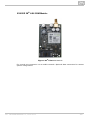
2N® Lift8
Communicator for lifts
User manual
Firmware
Version
1.5.2
1.5.2
www.2n.cz
The 2N TELEKOMUNIKACE a.s. is a Czech manufacturer and supplier of telecommunications
equipment.
The product family developed by 2N TELEKOMUNIKACE a.s. includes GSM gateways, private
branch exchanges (PBX), and door and lift communicators. 2N TELEKOMUNIKACE a.s. has
been ranked among the Czech top companies for years and represented a symbol of
stability and prosperity on the telecommunications market for almost two decades. At
present, we export our products into over 120 countries worldwide and have exclusive
distributors on all continents.
2N® is a registered trademark of 2N TELEKOMUNIKACE a.s. Any product and/or other
names mentioned herein are registered trademarks and/or trademarks or brands protected
by law.
2N TELEKOMUNIKACE a.s. administers the FAQ database to help you quickly find
information and to answer your questions about 2N products and services. On
www.faq.2n.cz you can find information regarding products adjustment and instructions for
optimum use and procedures „What to do if...“.
2N TELEKOMUNIKACE a.s. hereby declares that the 2N ® Lift8 product complies with all
basic requirements and other relevant provisions of the 1999/5/EC directive. For the full
wording of the Declaration of Conformity see the CD-ROM (if enclosed) or our website at
www.2n.cz.
The 2N TELEKOMUNIKACE a.s. is the holder of the ISO 9001:2009 certificate. All
development, production and distribution processes of the company are managed by this
standard and guarantee a high quality, technical level and professional aspect of all our
products.
Content
Content
1. Product Introduction . . . . . . . . . . . . . . . . . . . . . . . . . . . . . . . . 5
1.1 Product Description . . . . . . . . . . . . . . . . . . . . . . . . . . . . . . . . . . . . . . . . . . . . . . 6
1.2 Components and Associated Products . . . . . . . . . . . . . . . . . . . . . . . . . . . . . . . 8
1.3 Upgrade . . . . . . . . . . . . . . . . . . . . . . . . . . . . . . . . . . . . . . . . . . . . . . . . . . . . . . . 19
1.4 Terms and Symbols Used . . . . . . . . . . . . . . . . . . . . . . . . . . . . . . . . . . . . . . . . . 20
2. Description and Installation . . . . . . . . . . . . . . . . . . . . . . . . . . 21
2.1 PSTN/GSM/UMTS/VoIP Central Unit . . . . . . . . . . . . . . . . . . . . . . . . . . . . . . . . . 22
2.2 Splitter . . . . . . . . . . . . . . . . . . . . . . . . . . . . . . . . . . . . . . . . . . . . . . . . . . . . . . . . 34
2.3 Audio Unit – Cabin Universal . . . . . . . . . . . . . . . . . . . . . . . . . . . . . . . . . . . . . . . 37
2.4 Audio Unit – Machine Room . . . . . . . . . . . . . . . . . . . . . . . . . . . . . . . . . . . . . . . . 48
2.5 Audio Unit – Shaft . . . . . . . . . . . . . . . . . . . . . . . . . . . . . . . . . . . . . . . . . . . . . . . . 52
2.6 PSTN Module . . . . . . . . . . . . . . . . . . . . . . . . . . . . . . . . . . . . . . . . . . . . . . . . . . . 56
2.7 GSM/UMTS Module . . . . . . . . . . . . . . . . . . . . . . . . . . . . . . . . . . . . . . . . . . . . . . 58
2.8 VoIP Module . . . . . . . . . . . . . . . . . . . . . . . . . . . . . . . . . . . . . . . . . . . . . . . . . . . . 60
3. System Configuration . . . . . . . . . . . . . . . . . . . . . . . . . . . . . . . 62
3.1 Programming . . . . . . . . . . . . . . . . . . . . . . . . . . . . . . . . . . . . . . . . . . . . . . . . . . . 63
3.2 Table of Parameters (FW 1.5.2) . . . . . . . . . . . . . . . . . . . . . . . . . . . . . . . . . . . . . 67
4. Function and Use . . . . . . . . . . . . . . . . . . . . . . . . . . . . . . . . . . 78
4.1 User Instructions . . . . . . . . . . . . . . . . . . . . . . . . . . . . . . . . . . . . . . . . . . . . . . . . . 79
4.2 Control Centre Instructions . . . . . . . . . . . . . . . . . . . . . . . . . . . . . . . . . . . . . . . . . 81
4.3 Function Description (for Advanced Users) . . . . . . . . . . . . . . . . . . . . . . . . . . . . 83
4.4 Call Confirmation Types . . . . . . . . . . . . . . . . . . . . . . . . . . . . . . . . . . . . . . . . . . . 88
4.5 Lift Blocking Function . . . . . . . . . . . . . . . . . . . . . . . . . . . . . . . . . . . . . . . . . . . . . 91
4.6 Four-Lift Version . . . . . . . . . . . . . . . . . . . . . . . . . . . . . . . . . . . . . . . . . . . . . . . . . 92
4.7 Intercom Function . . . . . . . . . . . . . . . . . . . . . . . . . . . . . . . . . . . . . . . . . . . . . . . . 94
5. Service Tool . . . . . . . . . . . . . . . . . . . . . . . . . . . . . . . . . . . . . . . 96
5.1 Installation and Login . . . . . . . . . . . . . . . . . . . . . . . . . . . . . . . . . . . . . . . . . . . . . 97
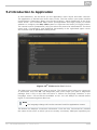
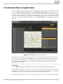
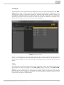
5.2 Introduction to Application . . . . . . . . . . . . . . . . . . . . . . . . . . . . . . . . . . . . . . . . . 100
5.3 Use . . . . . . . . . . . . . . . . . . . . . . . . . . . . . . . . . . . . . . . . . . . . . . . . . . . . . . . . . . . 106
6. Server . . . . . . . . . . . . . . . . . . . . . . . . . . . . . . . . . . . . . . . . . . . . 115
6.1 Installation and Licensing . . . . . . . . . . . . . . . . . . . . . . . . . . . . . . . . . . . . . . . . . . 116
6.2 Use . . . . . . . . . . . . . . . . . . . . . . . . . . . . . . . . . . . . . . . . . . . . . . . . . . . . . . . . . . . 119
7. Control Panel . . . . . . . . . . . . . . . . . . . . . . . . . . . . . . . . . . . . . . 123
7.1 Installation and Login . . . . . . . . . . . . . . . . . . . . . . . . . . . . . . . . . . . . . . . . . . . . . 124
7.2 Introduction to Application . . . . . . . . . . . . . . . . . . . . . . . . . . . . . . . . . . . . . . . . . 127
7.3 Use . . . . . . . . . . . . . . . . . . . . . . . . . . . . . . . . . . . . . . . . . . . . . . . . . . . . . . . . . . . 132
8. Communicator . . . . . . . . . . . . . . . . . . . . . . . . . . . . . . . . . . . . . 158
8.1 Installation and Login . . . . . . . . . . . . . . . . . . . . . . . . . . . . . . . . . . . . . . . . . . . . . 159
8.2 Introduction to Application . . . . . . . . . . . . . . . . . . . . . . . . . . . . . . . . . . . . . . . . . 162
8.3 Use . . . . . . . . . . . . . . . . . . . . . . . . . . . . . . . . . . . . . . . . . . . . . . . . . . . . . . . . . . . 165
9. Maintenance
. . . . . . . . . . . . . . . . . . . . . . . . . . . . . . . . . . . . . . 173
9.1 Operation Interruption and Battery Replacement . . . . . . . . . . . . . . . . . . . . . . . . 174
9.2 Firmware Upgrade . . . . . . . . . . . . . . . . . . . . . . . . . . . . . . . . . . . . . . . . . . . . . . . 176
10. Technical Parameters . . . . . . . . . . . . . . . . . . . . . . . . . . . . . . 177
11. Supplementary Information . . . . . . . . . . . . . . . . . . . . . . . . . 179
11.1 Troubleshooting . . . . . . . . . . . . . . . . . . . . . . . . . . . . . . . . . . . . . . . . . . . . . . . . 180
11.2 List of Abbreviations . . . . . . . . . . . . . . . . . . . . . . . . . . . . . . . . . . . . . . . . . . . . . 181
11.3 Regulations . . . . . . . . . . . . . . . . . . . . . . . . . . . . . . . . . . . . . . . . . . . . . . . . . . . . 182
11.4 General Instructions and Cautions . . . . . . . . . . . . . . . . . . . . . . . . . . . . . . . . . . 183
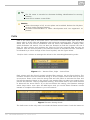
1. Product Introduction
In this section, we introduce the 2N® Lift8 product, outline its application options and
highlight the advantages following from its use.
Here is what you can find in this section:
1.1
1.2
1.3
1.4
Product Description
Components and Associated Products
Upgrade
Terms and Symbols Used
2N® TELEKOMUNIKACE a.s., www.2n.cz
5
1.1 Product Description
Basic Features
Up to 8-lift connectivity
Lift cabin, shaft and machine room voice audio units
Optimum acoustic properties
Rechargeable built-in backup battery
Easy control and configuration – voice response system
Check Call function
Lift blocking during connection failure
Internal communication – Triphony
Telephone/PC-based configuration (via USB or Internet)
USB interface
User message recording option
Local control centre (Intercom)
Fireman function
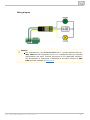
Basic Description
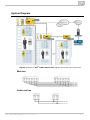
2N® Lift8 (L8) is a communication system with a function similar to an intercom. The
system voice audio units are linked to a common bus (pair of wires), connected to a
splitter. The splitter is always connected to a central unit (CU), which controls the
system operation and provides connection with the control centre. It is possible to
connect up to 40 audio units to the bus. The CU contains an internal splitter.
Each splitter is uniquely identified: by lift number 1 to 8. The audio units are connected
to the splitters and located on the shaft bottom, in the cabin interior, on the cabin roof
and in the machine room. The machine room audio unit can be shared by multiple lifts.
The CU contains an easily replaceable backup battery pack (lead rechargeable battery).
The CU is responsible for battery charging and status monitoring. It indicates the
charging state, signal strength, telephone line state, bus state core state via five colour
LEDs. It is also equipped with a USB interface for comfortable configuration, voice
message recording and software upgrade.
The CU can be connected via: GSM, UMTS, PSTN or VoIP.
2N® TELEKOMUNIKACE a.s., www.2n.cz
6
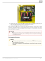
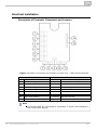
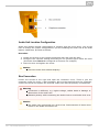
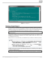
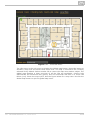
System Diagram
Figure: Example of 2N® Lift8 Central Unit, Splitter and audio unit Connection
Main bus
Audio unit bus
2N® TELEKOMUNIKACE a.s., www.2n.cz
7
1.2 Components and Associated Products
2N® Lift8 System Components
Notification
The components of the 2N® Lift8 system cannot be used outside this
system.
The audio units cannot be connected to a telephone line without the CU!
When shared by multiple shafts, the audio units cannot be connected
without the CU and splitters.
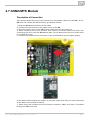
918600 2N® Lift8 Central Unit
Figure: 2N® Lift8 Central Unit
For connection of up to 8 lifts to a GSM/UMTS/PSTN line. Including a power EURO cable
and rechargeable battery. USB interface for configuration.
2N® TELEKOMUNIKACE a.s., www.2n.cz
8
918620E 2N® Lift8 Splitter
Figure: 2N® Lift8 Splitter
For CU – lift audio unit interconnection
918610E 2N® Lift8 audio unit – Cabin Universal
(Normal version)
Figure: 2N® Lift8 audio unit – Cabin Universal
Audio unit electronics for lift cabin buiiding in. Including speaker and microphone
(HandsFree). Connection terminals for all prescribed elements and door opening signal
input (optional).
2N® TELEKOMUNIKACE a.s., www.2n.cz
9
918610EX 2N® Lift8 audio unit – Cabin Universal – Cable Version
(Contains LED, microphone and speaker connected to cables)
Figure: 2N® Lift8 audio unit – Cabin Universal – Cable Version
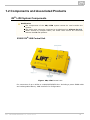
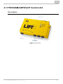
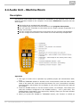
918611E 2N® Lift8 audio unit – Machine Room/Control Centre
Figure: 2N® Lift8 audio unit – Machine Room/Control Centre
Audio unit for the machine room/control centre. Contains receiver (optional) and
keypad for easy control. Makes it possible to communicate with other system audio
units and configure the CU without a PC. Equipped with an external siren connector.
Can be shared by multiple lifts (shafts). Robust yellow cover.
2N® TELEKOMUNIKACE a.s., www.2n.cz
10
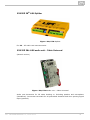
918612E 2N® Lift8 audio unit – Shaft
Figure: 2N® Lift8 audio unit – Shaft
Audio unit for cabin roof and shaft or cabin bottom. Robust yellow cover. HandsFree
mode, Alarm button and Triphony, LED indicators. Not intended for use in the cabin.
918620E 2N® Lift8 I/O Module
Figure: 2N® Lift8 I/O Module
Contains logical inputs and switch relays.
2N® TELEKOMUNIKACE a.s., www.2n.cz
11
918650E 2N® Lift8 GSM Module
Figure: 2N® Lift8 GSM Module
For central unit connection via a mobile network. Optional data connection for remote
system configuration.
2N® TELEKOMUNIKACE a.s., www.2n.cz
12
918651E 2N® Lift8 UMTS Module
Figure: 2N® Lift8 UMTS Module
For central unit connection via a mobile network. Optional data connection for remote
system configuration.
2N® TELEKOMUNIKACE a.s., www.2n.cz
13
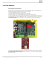
918652E 2N® Lift8 PSTN Module
Figure: 2N® Lift8 PSTN Module
For central unit connection via an analogue line.
2N® TELEKOMUNIKACE a.s., www.2n.cz
14
918653E 2N® Lift8 VoIP Module
Figure: 2N® Lift8 VoIP Module
For central unit connection via a VoIP line.
2N® TELEKOMUNIKACE a.s., www.2n.cz
15
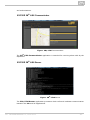
Cooperating 2N® Applications
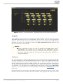
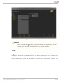
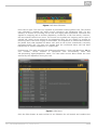
918700E 2N® Lift8 Service Tool
Figure: 2N® Lift8 Service Tool
The 2N® Lift8 Service Tool application is intended for remote supervision and
configuration of the 2N® Lift8 communicators.
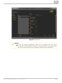
918700E 2N® Lift8 Control Panel
Figure: 2N® Lift8 Control Panel
The 2N® Lift8 Control Panel application is intended for administration of users, lifts
2N® TELEKOMUNIKACE a.s., www.2n.cz
16
and authorisations.
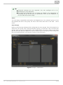
918700E 2N® Lift8 Communicator
Figure: 2N® Lift8 Communicator
The 2N® Lift8 Communicator application is intended for receiving alarm calls by the
dispatcher.
918700E 2N® Lift8 Server
Figure: 2N® Lift8 Server
The 2N® Lift8 Server application processes check calls and mediates communication
between the CUs and PC applications.
2N® TELEKOMUNIKACE a.s., www.2n.cz
17
Associated 2N® Products
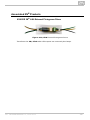
918655E 2N® Lift8 External Pictograms Driver
Figure: 2N® Lift8 External Pictograms Driver
Transforms the 2N® Lift8 cabin LED outputs into universal pilot lamps.
2N® TELEKOMUNIKACE a.s., www.2n.cz
18
1.3 Upgrade
The table below sums up the User Manual upgrade changes made so far.
Manual
version
Description of changes
Firmware 1.0.0
1.0.0
Basic version
Firmware 1.5.0
1.5.0
VoIP parameters added
Internal splitter four-lift configuration option
(up to four cabin units can be connected to one internal splitter
with lift 1–4 identification)
Intercom function
2N® TELEKOMUNIKACE a.s., www.2n.cz
19
1.4 Terms and Symbols Used
Symbols Used
The following symbols and pictograms are used in the manual:
Safety
Always abide by this information to prevent persons from injury.
Warning
Always abide by this information to prevent damage to the device.
Caution
Important information for system functionality.
Tip
Useful information for quick and efficient functionality.
Note
Routines or advice for efficient use of the device.
Future Functions, New Features
The grey-marked text in this document designates the functions and features that are
under preparation or development at present.
2N® TELEKOMUNIKACE a.s., www.2n.cz
20
2. Description and Installation
The section is divided according to system components into the following subsections:
2.1
2.2
2.3
2.4
2.5
2.6
2.7
2.8
PSTN/GSM/UMTS/VoIP Central Unit
Splitter
Audio Unit – Cabin Universal
Audio Unit – Machine Room
Audio Unit – Shaft
PSTN Module
GSM/UMTS Module
VoIP Module
Each subsection includes:
Description of Components
Before You Start
Fitting
Electrical Wiring
2N® TELEKOMUNIKACE a.s., www.2n.cz
21
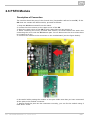
2.1 PSTN/GSM/UMTS/VoIP Central Unit
Description
Figure: Central Unit
2N® TELEKOMUNIKACE a.s., www.2n.cz
22
Figure: Central Unit Indication Elements
2N® TELEKOMUNIKACE a.s., www.2n.cz
23
Figure: Central Unit Connectors
Lift blocking contact
A … NC relay contact for lift blocking
(normally closed)
B … C relay contact for lift blocking
C … NO relay contact for lift blocking
(normally open)
1…
+
2…
3…
+
4…
5…
+
6…
Main bus
main bus supply
main bus supply
Audio unit bus
7 … voice Audio
Unit bus +
8 … voice Audio
Unit bus -
main bus audio
main bus audio main bus data
main bus data -
There are a USB connector and reset button to the right of the CU (see the figure
below):
2N® TELEKOMUNIKACE a.s., www.2n.cz
24
Figure: USB Connector and Reset Button
Reset button function
Reset equipment – press the button quickly.
Restore factory values – press and hold the button until all the LEDs turn red.
Then release the button and wait until the SYSTEM LED flashes yellow. Now press
the button quickly to delete all the user settings.
Zero backup rechargeable battery life counter – press and hold the button
until all the LEDs turn red. Then release the button and wait until the
POWER/BATTERY LED flashes yellow. Now press the button quickly. Perform this
function after replacing the backup rechargeable batteries with new ones only!
Check system completeness – press and hold the button until all the LEDs
turn red. Then release the button and wait until the INTERNAL BUS LED flashes
yellow. Now press the button quickly to make the system supervise all the
installed equipment (splitters, Audio Units etc.) for proper connection and
function.
Delete central unit software completely – press and hold the button until all
the LEDs turn red. Then release the button and wait until the SYSTEM LED
flashes red. Now press the button quickly. CAUTION: after performing this
function you can only restore the normal function of the device using a PC!
USB Port Connection
Recommendation
Do not keep your PC connected for a long time unless necessary to reduce the
computer damage due voltage surge from the telephone line during storms, for
example.
Warning
Do not open the CU during the warranty period.
Open the CU only to replace the rechargeable batteries after the
warranty period.
2N® TELEKOMUNIKACE a.s., www.2n.cz
25
Before You Start
CU installation conditions
The Central Unit (hereinafter referred to as CU) is not intended for outdoor use.
Do not install the CU onto vibration-producing machines.
Install the CU vertically to allow air flow for cooling purposes (never cover the CU
with any cloth or install it in another closed box).
You may install the CU into the lift switchboard unless the temperature exceeds
the acceptable limit. Remember that a higher ambient temperature reduces the
life of backup rechargeable batteries in the CU.
It is recommended that the CU should be operated in the upright position with
the cable openings at the bottom. Such mounting position ensures the lowest
temperatures and thus the longest life of the rechargeable batteries. Horizontal
mounting is also possible. The upright position with the cable openings at the top
(upside down) is forbidden!
After mounting the CU check that the equipment is firmly fixed in place and
cannot come loose and drop down into the shaft.
Product Completeness Check
Check whether the product package is complete before installation:
1 central unit
1 main bus terminal
4 bus connection terminals
4 wall plugs
4 wall plug screws
8 cable ties
1 battery connecting cables
1 brief manual
1 warranty sheet
drilling template
CU Mounting
It is recommended to install the CU in a room that is secured against unauthorised
persons, such as the lift machine room, switching station etc. On an easily accessible
place there is a risk of telephone line misuse or SIM card misappropriation .
The CU is mounted on a wall with the included wall plugs and screws.
2N® TELEKOMUNIKACE a.s., www.2n.cz
26
CU Electrical Installation
Putting in operation
1.
2.
3.
4.
5.
6.
7.
8.
9.
10.
Keep the CU disconnected from the mains.
Loosen the three screws on the upper cover of the CU.
Move the upper cover of the CU in such a way that you can remove it.
When removing the cover, proceed with caution, be careful about the earth wire
connecting the cover with the CU bottom part. Do not disconnect the wire unless
there is a reason to do so!
Using the slide-on terminals supplied with the device, connect the Audio Units,
splitters (if there are 2 and more lift shafts) and other components of the system
with the CU. Adhere to polarity!
Install a PSTN, GSM or UMTS module unless installed on the CU. Abide by the
instructions given in the Instructions for Use of the given module (refer to Subs.
2.7 or 2.8).
Connect an analogue telephone line to the PSTN module if used (use a telephone
connector or the terminal board on the module). Do not forget to connect an
antenna to the GSM/UMTS module is used and insert a SIM card!
Connect the rechargeable battery jumper link (see the next subsection –
Rechargeable Battery State Check) to activate the rechargeable battery function.
Replace the upper cover on the CU and tighten the cover fitting screws. Doing so
make sure that the earthing wire is connected to the cover!
Connect the CU power cable to a 230V socket.
Caution
If you connect one lift shaft only, it is not necessary to connect the
splitters. Use the splitters only if you want to connect 2 or more lift shafts.
Power supply
The CU is powered by 100–240V mains power.
Warning
Never connect an AC source or unstabilised DC source to avoid CU
damage.
Rechargeable Battery Connection and State Check
Procedure:
1.
2.
3.
4.
Keep the CU disconnected from the mains.
Loosen the three screws on the upper cover of the CU.
Move the upper cover of the CU in such a way that you can remove it.
When removing the cover, proceed with caution, be careful about the earth wire
connecting the cover with the CU bottom part. Do not disconnect the wire unless
there is a reason to do so!
5. Interconnect the rechargeable batteries and connect them with the motherboard
using a FASTON cable (see the figure below). Mind the polarity.
2N® TELEKOMUNIKACE a.s., www.2n.cz
27
5.
6. Replace the upper cover on the CU and tighten the cover fitting screws. Doing so
make sure that the earthing wire is connected to the cover!
7. Connect the CU power cable to a 230V socket.
After plugging the CU into the socket the LED (Power/battery) should start to flash
(charging). The CU charges the rechargeable batteries until fully charged. After some
time the flashing green LED (charging) should change to a permanently illuminated
green LED (battery charged).
Warning
Adhere to the polarity of the rechargeable batteries! When the polarity of
the batteries is reversed, there is a danger of fire or explosion or damage
to the CU electronics.
Rechargeable Batteries
Caution
If backup rechargeable batteries are used for the 2N® Lift8 power supply,
the required backup of up to 1 h is guaranteed only if up to 20 audio units
are connected in the system.
The required 1h backup is not guaranteed if more than 20 audio units are
installed.
2N® TELEKOMUNIKACE a.s., www.2n.cz
28
Splitter – CU Bus Connection
Interconnect the CU and splitter using a 6-wire main bus (power + - , audio + - , data
+ - ). Mind the polarity.
2N® TELEKOMUNIKACE a.s., www.2n.cz
29
Main bus
1 … Main bus power +
2 … Main bus power 3 … Main bus audio +
4 … Main bus audio 5 … Main bus data +
6 … Main bus data -
Caution
6-wire
Use unshielded wires of the cross-section of 0.75 mm2.
The maximum total cable length is 30 m with the cross-section of
0.75mm2.
For higher lengths, enlarge the supply pair cross-section: PWR
(60m–1.5mm2 , or 100m–2.5mm2).
Audio Units – Splitter (CU) Bus Connection
(the CU is used if one lift shaft is connected)
Interconnect the splitter (CU) and Audio Units using a two-wire bus. Mind the polarity.
Audio unit bus
1 … Bus for Audio Units +
2 … Bus for Audio Units Caution
2-wire
Use unshielded wires of the cross-section of 0.75 mm2.
The maximum total length per shaft is 600 m.
With multi-strand cables, always use a pair of wires which match
each other.
With a tow cable, consider the cable length too.
With special cables (to the cabin), use the neighbouring wires and
make sure that the nearest surrounding wires do not radiate
interference (power wire, video signal etc.).
2N® TELEKOMUNIKACE a.s., www.2n.cz
30
Tip
Do not lead the bus close to power cables, especially in long-distance
sections.
Branch the bus to shorten the total length of sections.
Safety
The bus is electrically isolated from the telephone line circuits according to
the EN60950 standard requirements and its low voltage cannot cause any
electrical accident.
CU Connection to Telephone Network
You can connect the CU to any of the following telephone networks:
PSTN
PBX
GSM
UMTS
VoIP
PSTN
2N® Lift8 works in a broad band regardless of polarity and line parameters (refer to
Technical Parameters). Connect it using the enclosed cable with an RJ–12 terminal. It
is the most reliable and simplest connection. The disadvantage is the operating cost
(fixed fee).
Caution
Only one CU may be connected to one telephone line and no other end
telephone equipment may be connected to the line including a product
through which the telephone line goes (so-called priority connection –
electronic burglar alarm, e.g.).
No dual or party lines may be used.
No telephone “multiplugs” (adaptors), even the smart ones, may be used.
Never connect 2N® Lift8 to an ISDN line.
Telephone line requirements:
The line must not be a dual or party one.
The telephone socket and its wiring are usually the network provider's property
and may not be tampered with.
Other recommendations:
Notify the telephone network provider of your 2N® Lift8 installation and submit
certification upon request.
Your follow-up wiring must comply with the relevant safety regulations.
You are recommended to secure your cabling against pirate connection (with a
telephone lock, e.g.).
2N® TELEKOMUNIKACE a.s., www.2n.cz
31
Connection via PBX (Private Branch Exchange)
This is the least-cost solution where a PBX and an unused PBX line are available.
PBX line requirements:
The PBX to be used must work reliably even in the case of power outage. Large
PBXs are mostly equipped with a back-up power supply, smaller PBXs usually use
PSTN line redirection in the event of power failure. Consult the problem with the
technician responsible for your PBX. An error during power outage may result in
2N® Lift8 calling an undesired station.
Relevant call access rights have to be assigned to the PBX line to be used (use a
standard telephone set to check whether the line can make outgoing calls to all
the required numbers).
While programming, enter the necessary PSTN code (typically a zero), or
(preferably) make the PBX not require a prefix (so-called automatic connection to
the provider's telephone line).
To make the control room – lift calls, you have to know the extension number
and how to get through to it (dial-in, DISA, operator).
The control room – lift connection may not depend on the operator’s presence;
no call forwarding to a fax/answering machine in the night mode is allowed, etc.
Other recommendations:
Make an agreement with the PBX owner regarding operating costs (2N® Lift8
outgoing calls are billed at the owner‘s expense with the exception of free calls
via “green lines”).
Tip
If there is permanent manning in your building (security staff,
receptionist), train the personnel how to rescue people and program 2N®
Lift8 to call this service.
GSM
This is used in particular where no PSTN line is available.
Recommendation
In places with a poor signal quality find an appropriate place or use a special
(directional) antenna.
Protect the SIM card from theft.
If a prepaid SIM card is used, make sure that the credit is monitored and
topped up in time.
UMTS
This is used in particular where no PSTN line is available. If 2N® Lift8 is connected via
UMTS, the system can be configured remotely using the 2N® Lift8 Service Tool appli
cation.
2N® TELEKOMUNIKACE a.s., www.2n.cz
32
Recommendation
In places with a poor signal quality find an appropriate place or use a special
(directional) antenna.
Protect the SIM card from theft.
If a prepaid SIM card is used, make sure that the credit is monitored and
topped up in time.
Operation without SIM card or PSTN line
2N® Lift8 can be used as an intercom without an inserted SIM card or connected
PSTN line during the lift fitting time. In this case do not enable the lift blocking
function until the telephone line is connected.
VoIP
VoIP is the cheapest solution where a reliable Internet connection is available.
2N® TELEKOMUNIKACE a.s., www.2n.cz
33
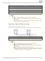
2.2 Splitter
Description
The splitter helps connect the CU with the lift Audio Units. It is connected with the CU
via six wires (power, audio, data). The Audio Units (audio units) are connected to the
splitter using a two-wire bus. The splitter also contains a make/break contact for the
lift blocking function. There can be up to 7 splitters (according to the count of lift
shafts).
Each splitter must be configured for a different address (lift shaft number) for the
system to work. The addresses are 2–8 (lift 2–8). Lift 1 is the CU.
The splitters are connected in series, i.e. one after another (never in parallel), to avoid
system instability. A termination resistor (jumper) is mounted on the last splitter
(furthest from the CU).
Figure: 2N® Lift8 Splitter
Caution
Local power supply is not supported yet.
2N® TELEKOMUNIKACE a.s., www.2n.cz
34
Electrical Installation
Main Bus Connection
Remove the push-in terminal board from the main bus connector and connect six wires
from the CU maintaining the polarity (power + -, audio + -, data + - ). See the printed
figure on the splitter cover.
Main bus
1 … Main bus power +
2 … Main bus power 3 … Main bus audio +
4 … Main bus audio 5 … Main bus data +
6 … Main bus data Warning
Maintain the connection polarity to avoid a 2N® Lift8 error.
Bus Connection between Audio Units and Splitter
Interconnect the splitter and Audio Units using a two-wire bus. Mind the polarity.
Audio unit bus
1 … Bus for Audio Units +
2 … Bus for Audio Units -
Address Configuration
Configure the splitter address for the given lift using a 10-position switch 0–9 (see the
figure).
2N® TELEKOMUNIKACE a.s., www.2n.cz
35
Configure lift 2–8 as 2–8 (set the switch to position 5 for lift 5, e.g.).
Audio Unit Connection
Connect up to 5 Audio Units to each splitter. As the splitter has only 3 audio unit
terminals, connect 1–2 Audio Units in parallel. Remove the slide-on terminals from the
audio unit connectors and connect the twin-wire. Adhere to polarity to avoid the Audio
Unit error. Refer to the schemes printed on the splitter and Audio Unit for t he
connection polarity.
Requirements
Connect up to 2 Audio Units to one terminal.
With multi-strand cables, always use a pair of wires which match each other. In
standard UTP cables the paired wires are twisted around each other.
With special cables (to the cabin), use the neighbouring wires and make sure
that the nearest surrounding wires do not radiate interference (power wire, video
signal etc.).
Recommendation
Do not run the bus near power wires, especially long sections.
Branch the bus to shorten the total length of sections.
Warning
The bus is electrically isolated from the telephone line circuits according to
the EN60950 standard requirements and its low voltage cannot cause any
electrical accident.
Lift Blocking Function Connection
Lift blocking is enabled by the contact breaking (opening) when there is a telephone
line (PSTN, GSM, UMTS) fault or if the 2N® Lift8 rechargeable batteries are almost
flat. Connect the contact to the relevant input of the control electronics of the lift/group
of lifts. The control electronics must ensure that, after the contact opening, the lifts in
operation go down to the nearest station and the doors open.
Caution
This function may be mandatory depending on the regulations applicable
for the given country and time of installation.
Termination Resistance
Caution
There is one more pin between the main bus connector and lift number
configuration, which helps you configure the termination resistance on the
last splitter connected (the furthest from the CU).
The termination resistance jumper is disabled by default.
2N® TELEKOMUNIKACE a.s., www.2n.cz
36
2.3 Audio Unit – Cabin Universal
Description
The user does not come into a direct contact with this product. The control and
indication elements depend on the specific installation. The functions of the indication
elements correspond to the applicable standards
Figure: Audio Unit – Cabin Universal
Before You Start
Installation Conditions
The panel has to be installation-ready, including speaker perforation.
The panel has to be equipped with the following obligatory elements:
ALARM button;
illuminated pictogram “Request received”;
illuminated pictogram “Connection made”.
The above mentioned elements have been located as required by the applicable
regulations.
There must be free space of at least 65×130×20 mm behind the panel.
2N® TELEKOMUNIKACE a.s., www.2n.cz
37
Product Completeness Check
Check the product for completeness before installation.
The cabin Audio Unit package contains (assembled):
1
4
1
1
1
1
1
5
electronics board
terminals slid onto the board; see the photo
jumper slid onto the board; see the cover printing
mounting panel
speaker connected directly or by cable
microphone connected directly or by cable
cover with printing
tightening straps
Mounting
Electronics Mounting
This Audio Unit is intended for mounting behind the lift control panel. Typically, the
panel is ready for installation as shown in the drawing below:
Figure: Mounting Hole Dimensions for Audio Unit – Cabin Universal
2N® TELEKOMUNIKACE a.s., www.2n.cz
38
To mount the Audio Unit, you need 4 electrically spot welded M3 or M4 screws, a
sufficiently perforated speaker area and a microphone hole. In emergency, you can fix
the Audio Unit on a perfectly degreased surface with a high-quality double-sided foam
self-adhesive tape.
Safety
Leave no gap between the lift control panel and the Audio Unit surface to
avoid acoustic speaker fault and acoustic speaker-microphone feedback.
Do not use this type of Audio Unit in a position other than mounted on a
sufficiently large board. The acoustic properties of an uninstalled Audio
Unit cannot be guaranteed.
Separate Microphone Mounting
If the microphone is supplied separately with a cable on a 25×25 mm large board with
self-adhesive foil, just glue it directly behind any hole in the panel (one hole must have
the minimum diameter of 5 mm, a group of smaller holes must have the same total
area). Be sure to degrease and clean the surface carefully before!
Requirements
The minimum distance between the loudspeaker and microphone centres
is 90 mm. A lower distance may lead to acoustic feedback. A greater distance
(within the available 1m cable) does not matter.
The microphone must be stuck on so that it does not pick up (even in part!) the
acoustic pressure from the space behind the control panel. Such sensing might
result in acoustic feedback since the speaker strongly radiates sound into the
cavity.
Separate Speaker Mounting
The speaker is equipped with a cable and can be separated from the electronics (simply
pulled out) within the reach of the cables delivered (1m). This option is useful where
there is not enough space for the whole electronic equipment. Fit the speaker
according to the instructions below:
While gluing the speaker choose such procedures or adhesives that prevent
membrane damage by adhesives and volatile substances or heat.
We recommend you to keep the speaker sealed to eliminate vibrations and
provide electrical insulation.
Frequently Asked Questions about Speaker
Is it possible to use a common speaker for the communicator and floor Audio
Unit?
No, it is not possible.
May I use a speaker of my own?
Yes, but make sure that the impedance is 64 Ω. By doing this you assume
responsibility for sufficient volume and frequency range.
May I place the speaker on the cabin ceiling?
This placement is not recommended.
May I use a longer cable to the speaker?
For the speaker yes, but we do not recommend it for the microphone.
2N® TELEKOMUNIKACE a.s., www.2n.cz
39
Electrical Installation
Description of Terminals, Connectors and Jumpers
Figure: Terminals, Connectors and Jumpers on Audio Unit – Cabin Universal Board
1
Terminals
Audio unit bus
7
Connectors
“Connection made” LED
2
ALARM, voltage activation
8
“Request received” LED
3
ALARM, contact activation
9
microphone connector (optionally)
4
CANCEL, voltage activation
10
induction loop connector
5
CANCEL, contact activation
11
speaker connector
6
Alarm 2 (set 2)
13
servicing connector
12
Configuration jumpers
Audio Unit position
Two LED signal lamps (other side)
1. (yellow) Request received
12
ALARM and CANCEL negation
2. (green)
Connection confirmed
Note
If external LEDs are connected to connectors 7 and 8, LED indicators 1
and 2 will not be shining.
2N® TELEKOMUNIKACE a.s., www.2n.cz
40
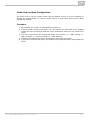
Audio Unit Location Configuration
The Audio Unit is set as a cabin Audio Unit by default and so it is not necessary to
change the configuration. To use the Audio Unit in a room other than the lift cabin,
proceed as follows.
Procedure
1. Reconfigure the jumper on configuration jumper 12.
2. If there is poor access to the pins, you can remove the elecronics cover. Slightly
loosen the four screws and shift the cover downwards. Now you can remove the
cover.
3. The first 4 pins serve for setting the Audio Unit location (1 – cabin ceiling, 2 –
cabin, default, 3 – under the cabin, 4 – shaft bottom).
4. Configure the required changes as printed on the electronics cover.
5. If you have removed the cover, put it back in the original position and tighten the
screw.
2N® TELEKOMUNIKACE a.s., www.2n.cz
41
Figure: Address Configuration for Audio Unit – Cabin Universal
Note
Make sure that two audio units do not have an identical address to avoid
system error.
The position-setting jumpers are employed exceptionally, e.g. where a
certain audio unit type is used in a position other than normally intended.
To recover the initial address setting, follow the drawing on the cover.
Bus Connection
Polarity must be maintained.
2N® TELEKOMUNIKACE a.s., www.2n.cz
42
Warning
Connection to different, e.g. higher-voltage, cables leads to damage or
destruction of the Audio Unit.
Maintain polarity while connecting the Audio Unit to avoid Audio Unit
error.
Caution
The Audio Unit is powered via a 2-wire bus. Disconnection of these wires
results in the Audio Unit switch-off.
Avoid the Audio Unit address duplicity.
ALARM Button Connection
Requirements
The ALARM button design (colour, symbol, keypad surface, mechanical operation)
and location have to meet the requirements of the particular installation.
Button control
Requirements
The ALARM button has to be equipped with a make or break (NO/NC) contact
that is not connected with any other circuit.
None of the ALARM button terminals may be connected electrically with any other
electrical circuit and no voltage source other than the NO/NC contact may be
connected to them.
If one of the ALARM contacts is connected to another circuit, an appropriate
isolation strength according to the applicable standards has to be ensured
between the contacts.
Procedure
1. Leave the ALARM terminal in the lower position (3).
2. If you use a make contact, leave the jumper as it is (5th pin on jumper 12) –
ALARM without jumper fitted (factory setting).
3. If you use a break contact, fit the jumper (5th pin on jumper 12) – ALARM
inverted – jumper fitted.
Voltage control
Requirements
DC 12 to 48V voltage
The voltage signal must be active even during a power failure.
Procedure
1. Move the ALARM terminal two pins up into position (2).
2. For activation by voltage connection, leave the jumper as it is (5th pin on jumper
12) – ALARM without jumper fitted (factory setting).
3. For activation by voltage disconnection, fit the jumper (5th pin on jumper 12) –
ALARM inverted – jumper fitted.
2N® TELEKOMUNIKACE a.s., www.2n.cz
43
Warning
Ignoring the instructions above may lead to product damage.
CANCEL Input Connection (Door Contact, Optional)
This input helps cancel a rescue request if the lift is fully functional. When the ALARM
button is pressed, the system waits for a pre-programmed period of time, which is a
little longer than the maximum lift running time. If the lift is functional, it arrives in the
required station within this timeout and opens the door. In that case, the rescue
request is cancelled. If the door does not open, the request is accepted.
Find out before installation whether the door opening signal is available in the lift cabin.
Requirements
If the lift has a double door, the signal must be active only if both the door sets
are open, i.e., if it is really possible to leave the cabin.
The door position signal has to work even in the case of power outage.
Contact control
Requirements
None of the contact outlets terminals may be connected electrically with any
other electrical circuit and no voltage source other than the NO/NC contact may
be connected to the CANCEL terminals.
Procedure
1. Leave the CANCEL terminal in the lower position (5).
2. f you use a make contact, leave the jumper as it is (6th pin on jumper 12) –
CANCEL without jumper fitted (factory setting).
3. If you use a break contact, fit the jumper (6th pin on jumper 12) – CANCEL
inverted – jumper fitted.
Voltage control
Requirements
DC 12 to 48V voltage
Procedure
1. Move the CANCEL terminal two pins up into position (4).
2. For activation by voltage connection, leave the jumper as it is (6th pin on jumper
12) – CANCEL without jumper fitted (factory setting).
3. For activation by voltage disconnection, fit the jumper (6th pin on jumper 12) –
CANCEL inverted – jumper fitted.
Warning
Ignoring the instructions above may lead to product damage.
The CANCEL function only works when the cabin Audio Unit is set to the
cabin position (default).
2N® TELEKOMUNIKACE a.s., www.2n.cz
44
Caution
Remember to program delayed calling to make the CANCEL connection
work successfully.
Refer to the electronics cover for the ALARM and CANCEL configuration
scheme.
LED Indicator Connection
The current LED technology makes it possible to achieve a relatively good light
intensity with a small current. If the lift indicators are illuminated with a sufficiently
efficient LED requiring a current of approx. 5 mA (with diode loss of about 2 V), no
power supply is needed. See the figure below for the connection.
Figure: Alternative LED Connection for Audio Unit – Cabin Universal
Note
The cables required for this configuration are not part of the standard
delivery but are available upon agreement.
In this configuration, the auxiliary indicators on the PCB are not
illuminated.
Induction Loop Connection
The regulations that apply to communicator installations may require a mandatory loop
for persons with defective hearing in the lift cabin. In that case, connect the loop to
connector (10) with any polarity. The loop including a 1m long cable can be part of
your delivery if agreed so.
Requirements
The induction loop has to be placed behind a non-metal, non-magnetic cover in
the control panel as the magnetic field of the induction loop cannot go through a
metal control panel.
The induction loop has to be labelled with an appropriate symbol (ear) placed
according to the applicable standards.
2N® TELEKOMUNIKACE a.s., www.2n.cz
45
Volume Configuration
Slightly loosen the four screws and shift the cover downwards. Now you can remove
the cover. Use the trimmer located in the bottom part of the electronics to set the
required volume level (see the figure below).
Caution
Use the trimmer to set the best acoustic properties eliminating feedback.
External Pictogram Driver
Description
The device transforms the 2N® Lift8 Car Unit LED outputs into a universal pilot lamp,
whose outputs are capable of driving two lamps rated at the maximum of 36 Volts, 0.5
Amps. The outputs are galvanically isolated from the Car Unit. Since the lamp outputs
are polarity independent, both AC and DC power supplies can be used for powering the
lamps. To protect the Car Unit and Pictogram Driver against damage caused by shorts,
always use the included isolating tube when installing the device!
2N® TELEKOMUNIKACE a.s., www.2n.cz
46
Wiring diagram
Caution
The manufacturer, 2N TELEKOMUNIKACE a.s., hereby declares that the
2N® Lift8 External Pictogram Driver is in compliance with the essential
requirements and other relevant provisions of the 1999/5/EC Directive.
The Declaration of Conformity is attached to the basic module of 2N®
Lift8 and also available at www.2n.cz.
2N® TELEKOMUNIKACE a.s., www.2n.cz
47
2.4 Audio Unit – Machine Room
Description
The machine room Audio Unit is intended for installation in the machine room or as an
intercom solution located in the reception. It has some distinctive compared with the
other types:
The Audio Unit is equipped with a keypad.
The keypad helps you select various functions and program the system.
You can connect a handset to the Audio Unit for better acoustic properties in a
noisy environment.
You can connect an external siren to the Audio Unit for incoming call signalling.
You can configure the machine room Audio Unit to be shared by multiple lifts.
Operation
1. This type of Audio Unit is operated by qualified people (lift maintenance staff,
e.g.).
2. Push the TRIPHONY button to activate voice communication with the other Audio
Units of the same lift. Push and hold the button for over 2 seconds to activate
communication with another lift (to display a voice menu and select the required
lift number).
3. Push the ALARM button to call the control centre, for example. The Audio Unit
calls the numbers configured in the ALARM memory – set 2 (021–026). The
ALARM button illumination (not required by default) helps you find and activate
the Audio Unit easily in the dark.
4. When you press the ALARM or TRIPHONY button, the function is called up
2N® TELEKOMUNIKACE a.s., www.2n.cz
48
4.
immediately. Speak HandsFree or use a handset for better acoustic properties.
5. Press
for more than 2 s to display the voice menu.
Caution
If no number is specified in the ALARM memory – set 2 (021–026), the
Audio Unit dials the numbers defined in the ALARM memory – set 1
(011–016).
Push the ALARM button to call the control room or machine room Audio
Unit configured as an intercom.
The ALARM and TRIPHONY buttons shine even at relax.
Before You Start
Requirements
Connect a handset supplied by the manufacturer to the Audio Unit to avoid
handset operation error.
Product Completeness Check
Check the product for completeness before installation.
1 Audio Unit
1 handset
2 wall plugs
2 wall plug screws
7–8 jumpers for common machine room configuration
Mounting
The Audio Unit is typically mounted on a wall using the wall plugs and screws included
in the delivery.
Electrical Installation
Description of Connectors
There are 3 connectors to the right under the cover:
2N® TELEKOMUNIKACE a.s., www.2n.cz
49
Figure: Machine Room Audio Unit Connectors
Address Configuration
There is a group of jumpers under the transparent front cover. Do not use any of them
if the machine room is only intended for the given lift. The Audio Unit identifies itself as
the machine room for the given lift.
If the machine room is to be shared by multiple lifts, configure the corresponding pins
1–8 for the lifts to share the machine room (numbered 1–8 from left to right 1–8).
Note
This Audio Unit is always configured as the machine room and cannot
have a different location.
Group of 8 jumpers for address configuration: If the machine room is shared by
multiple lifts, use one Audio Unit and configure several addresses using the included
jumpers. The other Audio Unit types do not have this possibility!
Note
Having set more addresses for the Audio Unit, press the TRIPHONY button
to activate communication of the lift Audio Units with the lowest of the
configured addresses.
Caution
Avoid the Audio Unit address duplicity.
Bus Connection
Open the side door. Pull out the terminal from the connector, connect the wires and
replace the terminal. Maintain the polarity.
2N® TELEKOMUNIKACE a.s., www.2n.cz
50
Warning
Connection to different, e.g. higher-voltage, cables leads to damage or
destruction of the Audio Unit.
Maintain polarity while connecting the Audio Unit to avoid Audio Unit error
.
Caution
The Audio Unit is powered via a 2-wire bus. Disconnection of these wires
results in the Audio Unit switch-off.
Handset Connection
Order an additional handset for your Audio Unit. The handset is delivered including a
cable with telephone end pieces.
Caution
If the handset is not connected, the Audio Unit works in the HandsFree
mode.
A handset of a type other than that supplied by the manufacturer may not
work.
Testing
Connect a handset and push and hold for over 2 s
to display the voice menu for
the function test. If the handset does not work, the voice menu will be played from the
Audio Unit speaker.
Volume Configuration
Open the protective door on the Audio Unit and adjust the volume using the trimmer.
Caution
Use the trimmer to set the best acoustic properties eliminating feedback.
Volume configuration only works in the HandsFree mode.
2N® TELEKOMUNIKACE a.s., www.2n.cz
51
2.5 Audio Unit – Shaft
Description
This Audio Unit is designed for installation on the lift shaft bottom or lift cabin roof, or
wherever it is necessary to communicate (during lift maintenance, e.g.). The Audio Unit
is enclosed in a robust yellow cover. It is not intended for outdoor use but perfectly
tolerates the conditions in lift shafts: is resistant against fall of small objects, dripping
oil, etc. The ALARM button activates the control centre connection, the TRIPHONY
bottom enables conference connection with the other Audio Units of one and the same
lift. The Audio Unit contains a built-in microphone and a speaker. A handset can be
connected for better acoustic properties. Thanks to its size and robustness, the Audio
Unit has a very good, strong sound.
Operation
1. This type of Audio Unit is operated by qualified people (lift maintenance staff,
e.g.).
2. Push the TRIPHONY button to activate voice communication with the other Audio
Units of the same lift.
3. Push the ALARM button, for example, when someone falls down the shaft.
4. The Audio Unit calls the numbers configured in the ALARM memory – set 2
(021–026).
5. The ALARM button illumination (not required by default) helps you find and
activate the Audio Unit easily in the dark.
2N® TELEKOMUNIKACE a.s., www.2n.cz
52
Caution
If no number is specified in the ALARM memory – set 2 (021–026), the
Audio Unit dials the numbers defined in the ALARM memory – set 1
(011–016).
Push the ALARM button to call the control room or machine room Audio
Unit configured as an intercom.
The ALARM and TRIPHONY buttons shine even at relax.
Before You Start
Product Completeness Check
Check the product for completeness before installation.
1 Audio Unit
2 wall plugs
2 wall plug screws
Requirements
This type of Audio Unit has no specific requirements.
Mounting
The Audio Unit is typically mounted on a wall using the supplied wall plugs and screws.
There is a drilling template in the product package.
Caution
The Audio Unit is not intended for outdoor installations.
Electrical Installation
Connectors
The Audio Unit has one connector for bus connection. The second RJ–11 connector is
used for handset connection. Both the connectors are under the side doors.
2N® TELEKOMUNIKACE a.s., www.2n.cz
53
Audio Unit Location Configuration
Audio Unit location means configuration of jumpers (see the cover print). You do not
have to change the jumper configuration if you are installing the Audio Unit at the shaft
bottom. Otherwise, proceed as follows:
Procedure
1. Loosen the screws on the jumper-protecting door and open the door.
2. Configure the required change according to the printed figure below the door
(this Audio Unit cannot be configured as common for multiple).
3. Close the door and tighten the screw.
Caution
Avoid the Audio Unit address duplicity.
Bus Connection
Loosen the screws to the right and open the connector cover. There is just one
connector under the cover: a bus connector. Pull out the terminal from the connector,
connect the wires and replace the terminal. Make sure that the polarity is maintained.
Warning
Connection to different, e.g. higher-voltage, cables leads to damage or
destruction of the Audio Unit.
Maintain polarity while connecting the Audio Unit to avoid Audio Unit error
.
Caution
The Audio Unit is powered via a 2-wire bus. Disconnection of these wires
results in the Audio Unit switch-off.
2N® TELEKOMUNIKACE a.s., www.2n.cz
54
Handset Connection
Use the handset supplied with the Audio Unit and the included cable with telephone
terminals.
Caution
If the handset is not connected, the Audio Unit works in the HandsFree
mode.
A handset other than that supplied by the manufacturer may not work.
Volume Configuration
Open the protective door on the Audio Unit and adjust the volume using the trimmer.
Caution
Use the trimmer to set the best acoustic properties eliminating feedback.
Volume configuration only works in the HandsFree mode.
2N® TELEKOMUNIKACE a.s., www.2n.cz
55
2.6 PSTN Module
Description of Connection
The module should be part of the Central Unit (hereinafter referred to as CU). If the
CU does not contain the PSTN module, proceed as follows:
1. Keep the CU disconnected from the mains.
2. Loosen the three screws on the upper cover of the CU.
3. Move the upper cover of the CU in such a way that you can remove it.
4. When removing the cover, proceed with caution, be careful about the earth wire
connecting the cover with the CU bottom part. Do not disconnect the wire unless there
is a reason to do so!
5. Connect the module to the connector on the motherboard (see the figure below).
6. Be careful while putting the module on the pins. Make sure that you have connected
all the pins to the module connector.
7. Having fitted the pins into the connector correctly, you can fix the module using 2
bolts and 1 screw.
2N® TELEKOMUNIKACE a.s., www.2n.cz
56
8. Now connect the PSTN line. There are 2 options:
using the RJ–11 connector;
using a slide-on terminal board.
Warning
While fitting the module, make sure that all the pins are fitted correctly
into the connector to avoid module damage.
2N® TELEKOMUNIKACE a.s., www.2n.cz
57
2.7 GSM/UMTS Module
Description of Connection
The module should be part of the Central Unit (hereinafter referred to as CU). If the
CU does not contain the PSTN module, proceed as follows:
1. Keep the CU disconnected from the mains.
2. Loosen the three screws on the upper cover of the CU.
3. Move the upper cover of the CU in such a way that you can remove it.
4. When removing the cover, proceed with caution, be careful about the earth wire
connecting the cover with the CU bottom part. Do not disconnect the wire unless there
is a reason to do so!
5. Connect the module to the connector on the motherboard (see the figure below).
6. Be careful while putting the module on the pins. Make sure that you have connected
all the pins to the module connector.
7. While fitting the module mind the antenna connector. Make sure that it is pushed
through the CU cover hole.
2N® TELEKOMUNIKACE a.s., www.2n.cz
58
8. Having fitted the pins into the connector correctly, you can fix the module using 2
bolts and 1 screw.
9. Now insert the SIM card and connect the antenna.
Warning
While fitting the module, make sure that all the pins are fitted correctly
into the connector to avoid module damage.
Caution
In places with a poor signal quality find an appropriate place or use a
special (directional) antenna.
Should you have DTMF transmission problems, set parameter 710 to 1
(for GSM modules only).
2N® TELEKOMUNIKACE a.s., www.2n.cz
59
2.8 VoIP Module
Description of Connection
The module should be part of the Central Unit (hereinafter referred to as CU). If the
CU does not contain the PSTN module, proceed as follows:
1. Keep the CU disconnected from the mains.
2. Loosen the three screws on the upper cover of the CU.
3. Move the upper cover of the CU in such a way that you can remove it.
4. When removing the cover, proceed with caution, be careful about the earth wire
connecting the cover with the CU bottom part. Do not disconnect the wire unless there
is a reason to do so!
5. Connect the module to the connector on the motherboard (see the figure below).
6. Be careful while putting the module on the pins. Make sure that you have connected
all the pins to the module connector.
7. Having fitted the pins into the connector correctly, you can fix the module using 2
bolts and 1 screw.
2N® TELEKOMUNIKACE a.s., www.2n.cz
60
8. Now connect the VoIP line via the RJ–45 connector.
Warning
While fitting the module, make sure that all the pins are fitted correctly
into the connector to avoid module damage.s
2N® TELEKOMUNIKACE a.s., www.2n.cz
61
3. System Configuration
The system is supplied pre-configured.
This section describes the 2N® Lift8 configuration. There are three ways how to progr
am 2N® Lift8.
3.1 Programming
3.2 Table of Parameters (FW 1.5.2)
2N® TELEKOMUNIKACE a.s., www.2n.cz
62
2N® TELEKOMUNIKACE a.s., www.2n.cz
63
3.1 Programming
The advantage of the 2N® Lift8 (hereinafter referred to as
programmed via the CU where all the parameters are stored.
to reconfigure anything to replace an Audio Unit and you can
multiple lift systems, for example. The memory is independent
L8) system is that it is
Hence, you do not have
program just one CU in
of the CU power.
Before You Start
Fill in all the values to be changed in the prepared form with a clear table of basic
functions.
If the L8 is not brand new, make sure that you have the correct servicing
password, and if you are not completely sure of your L8 configuration, execute
full initialisation (Warning: The servicing password is also initialised!).
L8 can be programmed in 3 ways: remotely via a telephone (telephone number),
using the machine room Audio Unit and/or using the service tool program
(connection via USB/IP address).
Make sure that your telephone supports tone dialling (key phones may cause
problems in some PBXs).
Caution
Warning: The servicing password is also initialised!
Access to Programming Mode
You can enter the programming mode during an incoming call (calling the L8 number)
or using the machine room Audio Unit (press
for over 2 seconds).
Use the voice menu (press 9 for administration and 1 for access to the programming).
Upon request, enter the servicing password as follows: servicing password
(do
not forget to put an asterisk after the password).
If the password is correct, L8 announces: “You have entered the programming
menu, select a parameter”.
The factory password is 12345 but you are recommended to enter a different password
to protect your device against unauthorised persons.
Note
The factory password is 12345 but you are recommended to enter a
different password to protect your device against unauthorised persons.
While entering the password, keep a limit of 60 seconds (or any other
value configured in the range between 10 and 1000 seconds) for each
character to avoid L8 hang-up.
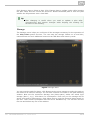
Programming Procedure
Having entered the programming mode, you can change any programmable value(s) in
any order. Proceed as follows: enter the function number and then the value. Use an
asterisk as a separator or Enter. In general, the function has the following format:
2N® TELEKOMUNIKACE a.s., www.2n.cz
64
function number
value
The function number has three digits (see the table). After you enter the function
number and an asterisk, L8 reports the number or name, current value and potential
range of the parameter to be programmed. After you enter the value and another
asterisk, L8 reports “New value stored”, or “Invalid value, new value not stored” if the
value is beyond the allowed range.
L8 reads out the parameter number and the newly configured value for checking
purposes.
Warning
A drawback of some telephone sets is that, after you press a button, i.e.
send a DTMF signal, they go “deaf” for a fraction of a second. In that
case, you cannot hear the whole text and are recommended to use
another telephone.
Programming Error
If you make a mistake during entering (the function number or value) and have
not entered an asterisk yet, you can cancel the whole number by pressing
and re-enter the number.
If L8 rejects the parameter number or value you have entered, go on
programming but re-enter the function number even if only the value was wrong.
If you have programmed and stored a value other than the required one, you can
re-enter the value of course.
Programming End
If you are calling L8 via a telephone number, hang up to terminate
programming.
If you are programming via the machine room Audio Unit, press and hold over 2
s
to terminate programming and put the Audio Unit in the standby mode.
If you only want to go one menu back, press
.
Tip
If you are not quite sure of how L8 will behave after programming, save
the filled-in form for later check.
Troubleshooting
L8 fails to respond correctly to DTMF commands, e.g. the programming mode cannot
be entered.
Today, voice transmission is prevailingly digital, using variable compression algorithms.
Therefore, the DTMF signal to be transmitted is often distorted. Moreover, it may, in
some cases, be transmitted through the so-called command channel, whose delay may
differ from that of the speech channel.
2N® TELEKOMUNIKACE a.s., www.2n.cz
65
Caution
Experience shows that, especially recently, it is practically impossible to
recover the DTMF signal in GSM networks!
In such cases, try some other equipment (a digital PBX, e.g.) or the machine room
telephone set. If the machine room or PSTN programming attempts fail too, you have
probably entered an invalid password.
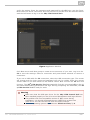
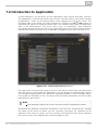
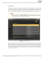
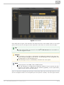
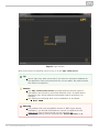
Programming via Service Tool
Refer to the 2N® Service Tool section (Section 5) for details.
2N® TELEKOMUNIKACE a.s., www.2n.cz
66
2N® TELEKOMUNIKACE a.s., www.2n.cz
67
3.2 Table of Parameters (FW 1.5.2)
Table of Parameters:
Parameter
No
011
012
013
014
015
016
Parameter Range of values Default
name
value
Set 1 –
up to 16
ALARM
empty
button
digits: 0–9
memory 1
Set 1 –
ALARM
button
memory 2
Set 1 –
ALARM
button
memory 3
Set 1 –
ALARM
button
memory 4
Set 1 –
ALARM
button
memory 5
Set 1 –
ALARM
button
memory 6
up to 16
empty
digits: 0–9
up to 16
empty
Entering characters
empty
a „p" to insert a 1
second pause when
programming is possible via
a PC (use the Service Tool).
,
digits: 0–9
up to 16
digits: 0–9
up to 16
empty
digits: 0–9
up to 16
empty
digits: 0–9
017
Insert
specific
character in
ALARM
memory set
1
018
Set 1 – count
of automatic
dialling
0–9
cycles for
ALARM
2N® TELEKOMUNIKACE a.s., www.2n.cz
Note
3
If 0 is configured, only the
first number in the memory
is called regardless of the
count of saved numbers.
68
111–116
021
022
023
024
025
026
027
Set 1 –
confirmation
mode for
number 1–6
Set 2 –
ALARM
button
memory 1
Set 2 –
ALARM
button
memory 2
Set 2 –
ALARM
button
memory 3
Set 2 –
ALARM
button
memory 4
Set 2 –
ALARM
button
memory 5
Set 2 –
ALARM
button
memory 6
1–6
1
1 = with confirmation DTMF
(1), 2 = confirmation of
picking up (supported only
for GSM/UMTS/VoIP), 3 =
CPC Antenna, 4= CPC
KONE, 5 = P100, 6 =
autodetection DTMF
protocol (CPC
Antenna/P100)
If there is no guarantee of
problem-free transfer of
DTMF, do not set 6 for
autodetection CPC
Antenna/P100, but
precisely specify the
protocol to be used (3 or
5).
up to 16
digits: 0–9
up to 16
digits: 0–9
up to 16
digits: 0–9
Entering characters
,
a „p" to insert a 1
second pause when
programming is possible via
a PC (use the Service Tool).
up to 16
digits: 0–9
up to 16
If the set 2 of alarm memo
ries is completely empty,
use the set 1 of ALARM me
mories.
digits: 0–9
up to 16
digits: 0–9
Insert
specific
character in
ALARM
memory set
2
2N® TELEKOMUNIKACE a.s., www.2n.cz
69
028
121–126
071
072
073
074
075
076
Set 2 – count
of automatic
dialling
0–9
cycles for
ALARM
Set 2 –
confirmation
mode for
number 1–6
Checking call
memory 1
Checking call
memory 2
Checking call
memory 3
Checking call
memory 4
Checking call
memory 5
Checking call
memory 6
077
Insert a
character in
checking call
memory
078
Count of
automatic
dialling
cycles for
checking call
2N® TELEKOMUNIKACE a.s., www.2n.cz
1–6
If 0 is configured, only the
first number in the memory
is called regardless of the
count of saved numbers.
1
1 = with confirmation DTMF
(1), 2 = confirmation of
picking up (supported only
for GSM/UMTS/VoIP), 3 =
CPC Antenna, 4= CPC
KONE, 5 = P100, 6 =
autodetection DTMF
protocol (CPC
Antenna/P100)
If there is no guarantee of
problem-free transfer of
DTMF, do not set 6 for
autodetection CPC
Antenna/P100, but
precisely specify the
protocol to be used (3 or
5).
up to 16
empty
digits: 0–9
up to 16
empty
Entering characters
empty
a „p" to insert a 1
second pause when
programming is possible via
a PC (use the Service Tool).
digits: 0–9
up to 16
digits: 0–9
,
up to 16
empty
digits: 0–9
up to 16
empty
digits: 0–9
up to 16
If the set of checking call
memories is completely
empty, use the set of
ALARM memories.
empty
digits: 0–9
0–9
3
70
171–176
081
082
083
084
085
086
Confirmation
mode for
checking call
memory 1–6
Error call
memory 1
Error call
memory 2
Error call
memory 3
Error call
memory 4
Error call
memory 5
Error call
memory 6
087
Insert
specific
character in
fault
reporting
memory
088
Count of
automatic
dialling
cycles for
ERROR
2N® TELEKOMUNIKACE a.s., www.2n.cz
1–6
1
1 = with confirmation DTMF
(1), 2 = confirmation of
picking up (supported only
for GSM/UMTS/VoIP), 3 =
CPC Antenna, 4= CPC
KONE, 5 = P100, 6 =
autodetection DTMF
protocol (CPC
Antenna/P100)
If there is no guarantee of
problem-free transfer of
DTMF, do not set 6 for
autodetection CPC
Antenna/P100, but
precisely specify the
protocol to be used (3 or
5).
up to 16
empty
digits: 0–9
up to 16
empty
digits: 0–9
up to 16
empty
digits: 0–9
up to 16
empty
digits: 0–9
up to 16
Entering characters
,
a „p" to insert a 1
second pause when
programming is possible via
a PC (use the Service Tool).
empty
digits: 0–9
up to 16
empty
digits: 0–9
0–9
3
71
181–186
Confirmation
mode for
number 1–6
1–6
1
1 = with confirmation DTMF
(1), 2= confirmation of
picking up (supported only
for GSM/UMTS/VoIP), 3 =
CPC Antenna, 4= CPC
KONE, 5 = P100, 6 =
autodetection DTMF
protocol (CPC
Antenna/P100)
If there is no guarantee of
problem-free transfer of
DTMF, do not set 6 for
autodetection CPC
Antenna/P100, but
precisely specify the
protocol to be used (3 or
5).
up to 16
700
SIM PIN
0000
digits: 0–9
0 = disabled, 1 = enabled
710
DTMF
transfer
enhanced
mode
enabled
909
Time for tone
detection
1000–9999 ms
after
hang-up
911
Count of
rings before
incoming call
pick-up
912
Max. call
time
0–1
1–9
0–1000 s
0
If there is a DTMF transfer
problem in the GSM
network, enable this
parameter.
5000 ms
L8 waits for the constant or
dialling tone. If none is
detected, there is a fault on
the line (PSTN only).
2
Define the moment of line
pick-up during ringing (if
there is an incoming call
from PSTN).
120 s
The call can be extended by
a call-extending command
(parameter 924).
0=disabled (never-ending
call).
913
Login time
limit
10–1000 s
60 s
Maximum period during
which the control centre
staff must answer the call
and send confirmation,
otherwise L8 hangs up and
proceeds to dialling the
next number. Counted from
the end of dialling.
914
Delayed call
0–1000 s
0s
Used only with connected
CANCEL input on the cabin
Audio Unit.
915
Max.
TRIPHONY
time
10–9999 s
7200 s
Maximum TRIPHONY period
after which TRIPHONY is
terminated automatically.
2N® TELEKOMUNIKACE a.s., www.2n.cz
72
917
Hang-up time
500–9999 ms
between calls
5000 ms
918
Max.
telephone
line test time
1–20s
5s
940
Min. dialtone
period
200–2000 ms
400 ms
The tone must be longer
than a half-period of the
busy tone!
941
Min. constant
200–9999 ms
tone time
2000 ms
If the tone lasts longer, L8
hangs up.
942
Min. busy
tone period
100–500 ms
200 ms
944
Max. tone –
gap
difference
10–400 ms
50 ms
945
Min. busy
tone period
count
2–50
5
948
Min. ringback
50–2000 ms
tone time
949
Min. long
space time of
100–5000 ms
ring-back
tone
For PSTN lines only.
These parameters control
the busy tone detection.
200 ms
The ringtone time is the
length of the section just
before the long gap.
2500 ms
The longest gap in the
ringing period must be in
the interval between
parameters 949 and 950.
950
Max. long
space time of 500–9999 ms
ringback tone
5500 ms
The longest gap in the
ringing period must be in
an interval between
parameters 949 and 950.
951
Min. ringing
signal time
200 ms
952
Min. long
space time of
100–5000 ms
ringing
signal
1000 ms
953
Max. long
space time of 500–9999 ms
ringing signal
6000 ms
961
Max. next
digit pressing 15–120 s
time
60 s
Counted from the transition
to a new state (NOT after
the end of announcement).
962
Min. cabin
ALARM
10–9999 ms
button
pressing time
100 ms
A low value is
recommended for
comfortable product
testing.
968
Machine
room alerting 1–60 s
time (siren)
1s
2N® TELEKOMUNIKACE a.s., www.2n.cz
50–2000 ms
Incoming call detection:
The ringtone time is the
sum of sections between
which there is no long gap.
The longest gap in the
ringing period must be in
the interval between
parameters 952 and 953.
CAUTION! Parameters
951–953 (default values)
work for incoming ringing.
73
969
Intercom
alerting time
1–60 s
1s
973
Language for
numeric
messages
0–1
1
974
975
Lift
identification
number
Local (cabin)
message
sequence
0 = user recorded
1 = voice menu language
up to 16 digits:
empty
0–9
up to 10
announcements in
sequence
(Alarm)
976
Control
centre
(outgoing)
message
sequence
977
978
979
971
Call
confirmation
message
sequence
Control
centre
(outgoing)
message
sequence by
pressing 3
after call
confirmation
Call end
sequence
2N® TELEKOMUNIKACE a.s., www.2n.cz
Start announcements in
more languages in a
defined sequence, including
the identification number,
etc.
Message list:
up to 10
announcements in
sequence
(before
confirmation
by 1)
Checking call
message
sequence
Provide lift identification for
foreigners, for example. If
not filled in, the serial
number is used.
up to 10
announcements in
sequence
up to 10
announcements in
sequence
01
02
03
04
05
06
07
08
09
10
=
=
=
=
=
=
=
=
=
=
User
User
User
User
User
User
User
User
User
User
message
message
message
message
message
message
message
message
message
message
1
2
3
4
5
6
7
8
9
10
11 = Serial number
12 = Lift identification
number (par. 974)
13 = Lift shaft number
(1–8)
14 = Pause (2 s)
15 = Confirmation tone
up to 10
announcements in
sequence
Cautions:
up to 10
User messages 1 to 10 are
recorded into the CU with
the aid of the 2N® Service
Tool.
announcements in
sequence
74
981
Checking call
982
Checking call
interval
983
Checking call
period
0 = disabled
1 = enabled, the first call in
3 minutes and then as set
in parameter 983
2 = enabled, the first call in
2 hours and then as set in
parameter 983
3 = enabled, as set in
parameter 983
4 = enabled, the call on the
nearest day set in
parameter 986
5 =enabled, the first call in
3 minutes and then as set
in parameter 983
0–5
0
hhmmhhmm
Set announcements into
lower traffic (lower tariff)
00002359
time, generated at random
in the time interval.
0–100 days
3 days
0 = disabled (0 in
parameter 981 has the
same effect), the value is
applied if parameter 981 is
set to 1–6.
Values for Mon, Tue, Wed,
Thu, Fri, Sat, Sun:
986
Weekdays for
MTWTFSS
checking call
0000000
0 = do not call
1 = call
Example:
1000100 = the checking
call will be made on
Mondays and Fridays.
991
992
Servicing
password
Rescue
password
12345
Change the default
servicing password for
access to programming via
the voice menu and for full
initialisation.
empty
Set the rescue terminating
password.
up to 16 digits:
0–9
up to 16 digits:
0–9
994
Enable 4-lift
version
0–1
0
995
Enable
outgoing
machine
room call
0–1
0
2N® TELEKOMUNIKACE a.s., www.2n.cz
0 = standard connection, 1
= connect up to 4 cabin
Audio Units to the CU
internal splitter as lifts 1–4
(refer to Subs. 4.5 for
details).
0 = disabled, 1 = enabled
(if the parameter is
enabled, the machine room
Audio Unit can be used for
outgoing public network
calls).
75
800
Set time
hhmm
Read the current time
setting and configure a new
one if necessary. *
801
Set date
RRMMDD
Read the current date
setting and configure a new
one if necessary. *
898
Cancel
working
configuration
Cancel all the changes
performed during this
configuration call except for
the date/time setting –
confirm this by an asterisk.
*
899
Complete
initialisation
(including
servicing
password!)
Re-enter the valid servicing
password to protect the
system against
unintentional deletion
during incorrect function
number entering. *
1001
Enable data
Permit the use of the
GSM/UMTS module
connection to the provider's
data network. **
1002
APN
Configure the mobile
provider's access APN
server. **
1003
Login
Configure the username for
authentication in the
provider's APN server. **
1004
Password
Configure the authorisation
password in the provider's
APN server. **
1100
Enable DHCP
client
0–1
0–1
0
1
The DHCP server assigns
PCs in particular the IP
address, net mask,
gateway and DNS server ad
dress via the DHCP.
0 = disabled
1 = enabled
1101
IP Address
1102
Netmask
1103
Default
gateway
1104
DNS server
2N® TELEKOMUNIKACE a.s., www.2n.cz
IP address defined for the
Ethernet interface (VoIP
module). **
Set the subnet bit mask. **
Set the IP address of the
router/PC via which
communication outside the
internal net is made. **
Set the DNS server IP
address. **
76
1105
SIP server
1106
User
1107
Password
1108
Enable
in-band
DTMF
detector
1109
SIP server
port
Set the IP address for
connection to the
counterparty (PBX,
operator). **
Set the user name for
connection to the
counterparty (PBX,
operator). **
Set the password for
connection to the
counterparty (PBX,
operator). **
0–1
1–65535
0
5060
Set the PBX (operator) port
via which the SIP Proxy
communicates with the
terminals connected. **
* This parameter can only be configured via the voice menu (incoming call to L8, or via
the Audio Unit machine room).
** This parameter can only be configured via the 2N® Service Tool.
Caution
Parameters 1003 and 1004 are used for username and password
configuration for verification at the provider's. Most providers do not use
any verification. If the your provider requires verification, it must give you
the necessary access data.
Configuration by Computer
Install the 2N® Service Tool to configure L8 connected to a PC via the USB or via the
Internet using the L8 IP address (UMTS version only). You can also upgrade of the
firmware.
Install and launch the 2N® Service Tool from the included CD for more details. Find
the current 2N® Service Tool version at www.2n.cz/Lift8 .
How to Record Announcement
From PC
Apply the 2N® Service Tool to record user announcements and numerals to 2N®
Lift8. Refer to Subs. 5.3, 2N® Service Tool – Use for details.
2N® TELEKOMUNIKACE a.s., www.2n.cz
77
4. Function and Use
In this section there is a description of the basic and expanded functions of the
product.
Here is what you can find in this section:
4.1
4.2
4.3
4.4
4.5
4.6
4.7
User Instructions
Control Centre Instructions
Function Description (for Advanced Users)
Call Confirmation Types
Lift Blocking Function
Four-Lift Version
Intercom Function
2N® TELEKOMUNIKACE a.s., www.2n.cz
78
4.1 User Instructions
Cabin
The cabin Audio Unit is intended for an untrained user. Nevertheless, the instructions
can be placed in the lift cabin, e.g., to help the people trapped in the lift communicate
with the control centre.
Meaning of pictograms (icons):
The yellow Wait icon is illuminated while connection with the control centre is
being set up.
The green icon lights up when connection has been set up and confirmed by the
control centre.
The green icon lights up whenever TRIPHONY is in progress.
The blue icon does not shine, but marks the place where a signal is radiated
during the call for people with defective hearing equipped with hearing aids.
Shaft, Cabin Roof
Press the ALARM button to call the control centre using the ALARM 2 numbers
(parameters 021–026). If the parameter is not filled in, it calls the ALARM
numbers (parameters 011–016) like the cabin.
Pressing the TRIPHONY button to call the other Audio Units in the same lift
(shaft).
Hold the TRIPHONY button (for approximately 2 s) to retrieve the voice menu to
call the other shafts via TRIPHONY.
Re-press the TRIPHONY button to terminate this connection.
The ALARM button is illuminated in the standby mode.
The ALARM button flashes when a calling is being set up.
The TRIPHONY button is not illuminated in the standby mode.
The TRIPHONY button flashes and the green LED indicator is illuminated if
TRIPHONY is active between the lifts.
The yellow LED indicator is illuminated if connection is being made with the
control centre.
The green LED indicator is illuminated if connection has been made and
confirmed by the control centre.
Machine Room
Everything that refers to the shaft Audio Unit applies here too. Press
(for longer
than 2 s) to display the machine room voicemenu. You can use the HandsFree mode
or connect a handset to achieve better acoustic properties.
Having entered the voice menu, you can select the following functions using the Audio
Unit keypad.
2N® TELEKOMUNIKACE a.s., www.2n.cz
79
Press 0 to dial the public telephone network
Select the lift X number to dial the lift
Press 1 to dial the lift cabin
Press 2 to dial the cabin roof
Press 3 to dial the lift cabin bottom
Press 4 to dial the shaft bottom
Press 5 to dial the machine room
Press # to return to the main menu
Press 9 for administration
Press 1 to enter the programming menu
Press 2 to terminate the rescue process
Press 3 to listen to your communicator info
1. Press to return to the main menu
Press # to end the call
Note
The 9 selection serves primarily for the L8 configuration – refer to the
Configuration section.
2N® TELEKOMUNIKACE a.s., www.2n.cz
80
4.2 Control Centre Instructions
ALARM Call
1. Press the ALARM button on any Audio Unit to make L8 call the control centre
(refer to Automatic Dialling for details).
2. A received call is either confirmed as configured (parameters 111–116 >
Confirmation mode for memory 1–6 ALARM call – set 1). By default,
confirmation of DTMF 1 is set in L8.
3. If the control centre is equipped with the 2N® Communicator application, you
can configure automatic sending of DTMF 1 after call pick-up.
4. The call is time limited (press button 4 upon warning announcement “Caution,
the call is ending” to extend the call).
5. You are recommended to end the by pressing 5 or #.
Control Room-to-Lift Calling
The control centre can also call back to the communicator. The CU automatically
receives every incoming call, identifies itself and, via a voice menu (DISA), offers you
another function to get through to the required Audio Unit. Incoming calls are time
limited as outgoing calls and are processed in the same way (extension, termination).
Incoming Call Voice Menu
Welcome, this is a 2N® Lift 8 communicator
Press 0 for connection with the last-calling Audio Unit
Enter the lift number X to dial another Audio Unit
Press 1 to dial the lift cabin
Press 2 to dial the cabin roof
Press 3 to dial the lift bottom
Press 4 to dial the shaft bottom
Press 5 to dial the machine room
Press # to return to the main menu
Press 9 for administration
Press 1 to enter the programming menu
Press 2 to terminate the rescue process
Press 3 to listen to your communicator info
Press # to return to the main menu
Press # to end the call
The menu above makes it possible to call the selected Audio Unit.
Caution
Press # to go one level back in the voice menu.
You can also terminate a call using #, but only on the highest voice menu
level: Press 0 for connection with the last-calling Audio Unit, Enter the lift
number X for connection with another Audio Unit, Press 9 for
administration, information or rescue process, and Press # to end the call.
2N® TELEKOMUNIKACE a.s., www.2n.cz
81
Calling to lift which was the last to call Alarm
Having entered the voice menu, press 0 to call the lift was the last to dial
the Alarm function.
This function operates only if you are calling to L8 via a PSTN, GSM, UMTS
or VoIP network.
Note
The 9 selection serves primarily for the L8 configuration – refer to the
Configuration section.
Tone Dialling Control during Call – Long Command List
Where automatic dialling with confirmation is used, it is possible to use tone dialling for
L8 control during the call according to the table below. For simplification, commands 1
to 5 are arranged in the sequence they are usually used in.
DTMF
symbol
Description of function
Only where automatic dialling repetition is enabled (with confirmation
DTMF 1). This symbol is used to confirm a successful call to L8. L8
mutes the played-back announcement and, optionally, sends the
identification code (DTMF). The call goes on until the timeout end and
any of the following commands may be used.
Repeated voice module playback for one replaying of the
announcement.
Call extension. The call is extended as defined in parameter 912
(120 seconds by default) upon this command. Can be used
repeatedly.
Call termination (does not work until the call is confirmed).
or
This table applies to the Automatic voice dialling with confirmation mode.
Warning
Rarely, L8 may not identify the above listed commands reliably during
message playing or voice communication. This is due to the essential
principle of the telephone line function where DTMF signalling is mixed
with the call and thus may be masked by certain speech tones or noise.
This, however, is not a defect of the product.
2N® TELEKOMUNIKACE a.s., www.2n.cz
82
4.3 Function Description (for Advanced Users)
Purpose of Section
The purpose of this section is to help technicians solve problems if any. If the system
fails to work properly and a well-trained technician, who monitors its operation step by
step according to the description included herein, gets to a point where the description
and reality are in contradiction, he or she describes the contradiction, thus facilitating
troubleshooting. This procedure often reveals that the system works properly but the
user had a different idea of how to use it.
Outgoing Call
The process starts whenever the ALARM button is pressed on any Audio Unit (in the lift
cabin Audio Units, the CANCEL input may delay or block calling, refer to parameter
914). After the ALARM button is pressed, L8 establishes connection with the control
office (refer to Automatic Dialling for details). L8 plays the following announcements
"Wait pleased, connection is being made“ to the person in the lift and "Press 1 for
confirmation” to the control centre (if DTMF 1 confirmation is used). The received call
has to be confirmed manually or automatically. The call is time-limited (“Caution, the
call is ending”, but can be extended.
Refer to the Control Centre Instructions subsection for details for DTMF control during
the call.
Caution
Icon
The ALARM buttons on the shart and machine room Audio Units are
always illuminated in the standby mode.
Outgoing Machine Room Calls
You can call any Audio Unit of the same L8 from the machine room (i.e. from the
machine room Audio Unit, Part No. 918611E), activate functions and configure the L8 p
arameters. Press and hold for over 2 s
to activate the machine room voice menu.
Press the TRIPHONY button to enter the machine room voice menu get through to the
other Audio Units of the same lift and set up triphony with the other shafts.
2N® TELEKOMUNIKACE a.s., www.2n.cz
83
Machine Room Voice Menu
Press 0 to dial the public telephone network
Press the lift number X to dial the lift
Press 1 to dial the lift cabin
Press 2 to dial the cabin roof
Press 3 to dial the lift bottom
Press 4 to dial the shaft bottom
Press 5 to dial the machine room
Press # to return to the main menu
Press 9 for administration
Press 2 to enter the programming menu
Press 2 to terminate the rescue process
Press 3 to listen to your communicator info
Press # to return to the main menu
Press # to end the call
Caution
Press # to go one level back in the voice menu.
Press and hold # (for longer than 2 s) or move to the top menu and press
# to quit the voice menu.
Triphony
Triphony provides interconnection of Audio Units within one shaft. Press the TRIPHONY
button in the machine room to set up triphony with another shaft.
This mode features a different setting of the automatic HandsFree mode: the
microphones of active Audio Units are less sensitive than those operating in the ALARM
mode.
Triphony termination options
re-pressing of the TRIPHONY button
expiry of the time limit
incoming call/ALARM – processed preferentially
Checking Call
A checking call is an outgoing call made automatically (usually every 3 days). The
purpose is to check the correct function of the system. This call is usually processed
automatically in the control centre.
A checking call can be sent to the control centre via PSTN, GSM, UMTS or VoIP. Set the
values in parameters 071–076 and 981 (refer to Subs. 3.2, Table of Parameters).
2N® TELEKOMUNIKACE a.s., www.2n.cz
84
Incoming Call
The control centre can also call back to the communicator. The CU automatically
receives every incoming call, identifies itself and, via a voice menu (DISA), offers you
another function to get through to the required Audio Unit. Incoming calls are time
limited as outgoing calls and are processed in the same way (extension, termination).
Press 0 in the voice menu for connection with the last-calling Audio Unit.
Incoming Call Voice Menu
Welcome, this is a 2N Lift 8 communicator
Press 0 to dial the last-calling Audio Unit
Enter the lift number X to dial another Audio Unit
Press 1 to dial the lift cabin
Press 2 to dial the cabin roof
Press 3 to dial the lift bottom
Press 4 to dial the shaft bottom
Press 5 to dial the machine room
Press # to return to the main menu
Press 9 for administration
Press 1 to enter the programming menu
Press 2 to terminate the rescue process
Press 3 to listen to your communicator info
Press # to return to the main menu
Press # to end the call
Call Sequencing
If another request arises during communication, the calls are ordered according to
priorities: Fireman has the highest priority, followed by Alarm. These calls suspend any
lower-priority call. Calls with identical priorities are queued and processed one after
another. Having done that, L8 recovers the suspended activity if possible.
2N® TELEKOMUNIKACE a.s., www.2n.cz
85
Ongoing:
new event
Incoming
call
Checking
call time
Entering
voice menu
from
machine
room Audio
Unit
TRIPHONY
button
press
ALARM
button
press
Fireman
function
Incoming
Checking
Programming
ALARM Triphony Fireman
call
call
na
ns
na
na/ns
S
ns
q
q
na
q
q
q
ns
ns
ns
ns
ns
ns*
ns
ns
ns
ns
ns
ns
S
S
q
q
S
q
S
S
S
S
S
na
Explanations:
na = not applicable
ns = not served (ns* for machine room configured as the control centre: the
Fireman call is entered whenever the phone is answered)
q = put in queue
S = suspends ongoing activity
Automatic Checking Call Answering
A control centre with a PC workplace with the 2N® Lift8 server receives calls
automatically as configured. Configure the server using the 2N® Lift8 Control Panel.
2N® TELEKOMUNIKACE a.s., www.2n.cz
86
Overview of Announcements
Announcement
(English)
Caution, the call is
ending
Meaning of announcement
Approaching call end announcement.
We are afraid the
call has to be
suspended
The call is interrupted by a requirement with higher priority.
Please wait
Wait until the call is put through.
Communicator
number…is calling
Identification (if configured). In the future, In the future, user
recorded messages including the lift address, e.g., will be
played.
Checking call
Checking call differentiation.
Rescue performed
Confirmation of the end of emergency signalling.
Other Audio Units
waiting for
connection
Warning that a state of emergency has been activated in the
other lifts.
Call End (Outgoing/Incoming)
A call is terminated (line hang-up occurs) if any of the following cases happens:
The busy or continuous tone has been detected*) (call end on PBXs).
The timeout for call confirmation expired (see parameter 913 setting).
The configured maximum call time has been exceeded (parameter 912). 10
seconds before the expiry, L8 plays “Caution, the call is ending” for you to
extend the call with
.
The
or
symbol has been received.
The time limit has expired during programming.
A higher-priority call request has arrived.
2N® TELEKOMUNIKACE a.s., www.2n.cz
87
4.4 Call Confirmation Types
The settings included in this subsection apply to alarm calls (sets 1,2), check calls and
trouble reports.
1. With DTMF Confirmation
Up to 6 telephone numbers plus the count of repetitions can be stored for control
centre dialling. L8 then tries to call all the numbers stored. Tone dialling (DTMF) is the
most reliable service for confirmation of successful calls. Having received a call
manually, the control centre officer has to press the
button on its tone-dialling
phone. If the called line is busy or unanswered within a timeout, or the call is not
confirmed, L8 dials the next number in the sequence until it exhausts all the pre-set
attempts. The procedure is the same for check calls or failure reports but a separate
group of six numbers can be used.
Evaluation of Situations in Dialling with Confirmation
Situation
No dialtone on
the line (PSTN
line only)
L8 activity
L8 hangs up.
Busy tone after
dialling end
L8 hangs up and dials the next number.
Call or silence
(after dialling
end)
L8 waits for the defined time (parameter 913).
Ringing tone
L8 waits for the defined time ( parameter 913).
Continuous tone
(on PBX line,
e.g.)
L8 hangs up and dials the next number.
DTMF char
L8 hangs up immediately and dials the next number.
or
DTMF char
L8 confirms receipt ("Connection confirmed") and mutes the
currently played announcement. The call goes on for the maximum
call time as configured.
These digits are interpreted as control characters (refer to Subs.
4.2, Tone Dialling Control during Call).
2N® TELEKOMUNIKACE a.s., www.2n.cz
88
Note
The PSTN connection quality is not so high as to identify the above
mentioned situations reliably in all cases. Moreover, excessive noise in the
lift cabin may decelerate automatic dialling (due to inability to recognise
the busy tone, e.g.). In general, DTMF is the most reliable type of
signalling and so is used for confirmation. Thus, the connection is
established (yet for a shorter time than usual) even in extreme cases, e.g.
when L8 cannot identify the DTMF.
2. Automatic Redialling of Multiple Numbers without
Confirmation (GSM/UMTS/VoIP Only)
This mode is useful where no trained personnel for automatic dialling with confirmation
are available. The called party does not have to press any button. The two modes
share a set of numbers and count of cycles, respond identically to the busy tone, etc.
The only difference is that the confirmation-less mode detects the ringing tone and
recognises that the called party is off-hook (i.e. answers the call) when the ringing
tone terminates before the timeout end.
The message speaker cannot be controlled using buttons
to
.
Evaluation of Situations in Voice Dialling without Confirmation
Situation
L8 activity
Busy tone
L8 hangs up in approx. 2 seconds and dials the next number.
Call/silence
L8 waits for the defined time (answering timeout), then hangs-up and
dials the next number.
Ringing
tone
L8 waits for the defined time (answering timeout), then hangs-up and
dials the next number.
Warning
Make sure in this mode that no VoiceMail box, FAX or any other
equipment are assigned to the numbers to be dialled that might answer
the call before the pre-programmed timeout end and thus terminate
automatic dialling.
3 and 4. CPC (Antenna and KONE)
Used wherever the counterparty is equipped with the required SW. When the line is
answered, a DTMF string is sent and the lift is identified. The call is either switched to
voice communication (alarm call) or confirmed automatically and terminated (check
call), as the case may be.
2N® TELEKOMUNIKACE a.s., www.2n.cz
89
5. P100
Used wherever the counterparty is equipped with the required SW. When the line is
answered, a DTMF character is sent and the lift is identified. The call is either switched
to voice communication (alarm call) or confirmed automatically and terminated (check
call), as the case may be.
6. DTMF Protocol AutoDetection (CPC/P100)
Having received a DTMF string, the lift recognises the protocol used and responds
accordingly.
Warning
L8 may have troubles detecting DTMF characters and recognising the
protocol in places with a poor signal quality.
If such troubles occur, we recommend you to change the CPC/P100 (3/4)
settings.
2N® TELEKOMUNIKACE a.s., www.2n.cz
90
4.5 Lift Blocking Function
Lift Blocking
Blocking procedure
The contact closes/opens whenever an alarm call cannot be set up. Connect the contact
to the appropriate controller input of the lift/group of lifts. The control electronics shall
ensure that, upon contact opening, the lifts that are in operation arrive in the nearest
station and open the door.
Every CU and every splitter are equipped with the lift blocking contact. Refer to Subs.
2.1, PSTN/GSM/UMTS/VoIP Central Unit – Lift Blocking Contact Connector.
The lift blocking function will be enabled if:
no number is defined in the ALARM memory – the lift gets blocked immediately.
a number to a non-existent machine room (intercom) is defined – the lift gets
blocked in 2 minutes.
a PSTN number is defined but no module is inserted – the lift gets blocked
immediately.
the external line (PSTN, VoIP) is not functional – the lift gets blocked in 15
minutes.
no SIM (GSM/UMTS) is inserted – the lift gets blocked in 15 minutes.
the capacity of the device feeding battery so low that the internal buses (Audio
Units) get disconnected – the lift gets blocked when the internal bus gets
disconnected.
L8 is off – the lift gets blocked immediately.
The lift blocking function will be disabled if:
the line works for 1 minute at least (PSTN, VoIP).
a power supply is connected to recharge the battery.
Caution
This function may be mandatory if the applicable regulations valid for the
country and time of installation require so.
2N® TELEKOMUNIKACE a.s., www.2n.cz
91
4.6 Four-Lift Version
4-Cabin Connection to Internal Splitter
Modify parameter 994 to allow up to 4 cabin Audio Units to be connected to the CU inte
rnal splitter as lifts 1–4. You can connect the machine room Audio Unit in this mode.
Set parameter 994 to 1.
Connect up to 4 cabin Audio Units.
Set each cabin Audio Unit to a different type (cabin roof, cabin, cabin bottom,
shaft bottom) using the adjustable pins (see the Audio Unit cover printing).
Connect the machine room Audio Unit to the CU internal splitter if necessary.
Figure: Zobrazení 4 kabinových jednotek na interním splittru
Warning
Make sure that each Audio Unit is assigned a different type (cabin roof,
cabin, cabin bottom, shaft bottom).
Note
You can use a shaft Audio Unit instead of the cabin one.
Normal 8-Lift Connection
If you set parameter 994 to 0, you can connect up to 8 lift shafts and up to 5 Audio
Units to each shaft (machine room, cabin roof, cabin, cabin bottom, shaft bottom).
2N® TELEKOMUNIKACE a.s., www.2n.cz
92
Figure: 8-Lift Configuration
2N® TELEKOMUNIKACE a.s., www.2n.cz
93
4.7 Intercom Function
ALARM – Intercom Calls
1. Press the
ALARM button on any Audio Unit (except for the machine room
Audio Unit set as the control centre) to start the process. Upon the press, L8
calls the pre-set machine room – control centre Audio Unit.
2. Press
or
(for longer than 2 s) to answer an incoming call.
3. When the call is answered by the operator, the L8 system announcement will be
played.Then, voice connection with the calling Audio Unit is activated.
a. Press 1 on the machine room Audio Unit keypad to confirm the received
call manually. If Confirmation by pick-up (011–016=2) is configured, it is
unnecessary to confirm the call with DTMF1 (refer to Tone Dialling Control
during Call – Long Command List for details).
4. The call is time-limited (by the "Caution, the call is ending” message), but can be
prolonged using button 4.
5. Press
, 5 or # to terminate the call.
Caution
You cannot set up an alarm call to another control centre from the
machine room Audio Unit that is configured as the control centre. The call
is made to the Audio Unit that is the last to activate the alarm call. If no
alarm call was activated on any Audio Unit, the machine room Audio Unit
will not call any unit.
Press
on the control centre Audio Unit to set up a call to the Audio
Unit that is the last to activate the ALARM function. Such a call is
processed as TRIPHONY and can be terminated by pressing the TRIPHONY
button on any of the two Audio Units or pressing and holding the
button for longer than 2 s on the machine Audio Unit.
If a call is set up to a non-existent machine room Audio Unit, the Alarm
function will not be activated (valid for settings #9, #0). If more numbers
than one are pre-programmed, the non-existent Audio Unit is skipped.
Number Setting for Machine Room – Control Centre Calls
Enter # before the shaft number to set the machine room number.
For example, 011 – #8 means that a call to the machine room Audio Unit in the shaft
of lift 8 is set in ALARM button memory 1.
Setting options:
1. Service Tool – enter # and the shaft number into parameters 011–016.
2N® TELEKOMUNIKACE a.s., www.2n.cz
94
1.
2. Enter the programming mode via the voice menu (incoming call or machine room
Audio Unit) and set the shaft number to the ALARM memory (011–016). Then
choose parameter 017 (refer to the Table of Parameters) and add the required
character (#) to one of the ALARM memories.
Caution
Configure the alarm-intercom connection for calls to the machine room
Audio Unit of any shaft (1–8).
Identically, configure the machine room – control centre connection for
ALARM set 2.
Make sure that the control centre Audio Unit is of the machine
room type.
You can use confirmation mode 1 or 2 for calling to a machine room Audio
Unit. With the other options (3–6), the call is processed as if 1 was
selected.
Note
It is possible to combine calling to the machine room (control centre)
Audio Unit with calling via the PSTN, GSM, UMTS and VoIP networks
(depending on the module used).
To set up a check call to a machine room Audio Unit, you can set the
number as described in the Alarm – Intercom subsection above.
2N® TELEKOMUNIKACE a.s., www.2n.cz
95
5. Service Tool
Here is what you can find in this section:
5.1 Installation and Login
5.2 Introduction to Application
5.3 Use
Refer to the 2N® Lift8 product pages at www.2n.cz, download section, for the latest
FW version. You can use this link from the online manual.
2N® TELEKOMUNIKACE a.s., www.2n.cz
96
5.1 Installation and Login
After the installation is launched, the installation program will scan your PC for another
2N® Lift8 Service Tool version and ask you to uninstall the currently available
version if identical with the new one. Use the system control panel Add or Remove
programs to uninstall the existing product version for reinstallation or reconfiguration.
If the versions are not identical, the original version will be uninstalled and a new
application version will be installed. Then you will also be asked whether the
configuration files should be removed and the whole application with a new, empty
database should be installed.
Now the 2N® Lift8 Service Tool Setup Wizard has been launched. Follow the wizard
instructions. Select the 2N® Lift8 Service Tool installation location: C:\Program
Files (x86)\2N TELEKOMUNIKACE\2N Lift8\ is used by default.
Also select whether the application should be installed for the currently logged-in user
or all the PC users. Now the wizard is ready to install the 2N® Lift8 Service Tool.
Confirm user account administration notification to the Windows system if necessary.
Another Start item and the application shortcut icon will be added automatically
Tip
The wizard will install the USB port driver if unavailable to identify the
Central Unit connected.
Note
The 2N® Lift8 Service Tool installation requires 500 MB of free disk
space at least.
Now the 2N® Lift8 Service Tool is ready for use. Click the shortcut item on the
desktop (see the figure below) or select the Start item to start the application.
Figure: 2N® Lift8 Service Tool Icon
After the application launch, the splashscreen gets displayed to inform you of the
application manufacturer and current version. After the launch, you will be in the basic
screen and Configuration / Parameters menu. Here an offline table of parameters can
be prepared for you to export the data or view the diagnostic packages. Click Connect
device to connect the CU in the Connect to device menu. Select the login mode: TCP or
USB. TCP is selected by default. If you choose the Advanced settings, the list of all
available connections to the 2N® Lift8 Central Unit will be displayed to the left in a
clearly arranged tree structure. If you have installed the application for the first time,
the default connection will be created automatically. This connection cannot be
removed. Set the correct connection parameters to connect the CU: simply enter the
name and CU public network IP address, fill in the DSN name if available and complete
the CU listening port, whose default value is 7007. Ask your network administrator to
2N® TELEKOMUNIKACE a.s., www.2n.cz
97
verify the setting. Enter the username and password for the CU login; see the figure.
Now select the server connection and click Connect or double-click the selected server
with the left button to log in to the 2N® Lift8 Central Unit.
Figure: Application Window
Click New server and New group to create a tree structure of your own. Log in to the
CU to save the settings. Select a connection and press Delete selected to remove a
connection.
If you use a USB cable for CU connection, select the USB connection type. The screen
will change and the login name and password will only be visible. Enter the correct
values. Refer to the text below for the default values. Now connect the CU and click
Connect. The 2N® Lift8 Service Tool automatically finds the connected CU on the PC
and starts downloading parameters and logs. Having completing the download, the 2N
®
Lift8 Service Tool is ready for work.
Warning
Make sure that the USB port driver for the 2N® Lift8 Central Unit has
been installed properly on the PC to avoid identification and login failures.
If a problem with non-compatible version of .NET occurs during
installation, you should download the new .NETFX4.0 version from
www.2n.cz. You can use this link from the online manual.
Minimum operating system requirements: Windows Vista, 7, 8.
2N® TELEKOMUNIKACE a.s., www.2n.cz
98
Caution
Default values for CU connection:
TCP
Username: Admin
Password: 2n
Port: 7007
USB
Username: Admin
Password: 2n
2N® TELEKOMUNIKACE a.s., www.2n.cz
99
5.2 Introduction to Application
In this subsection, we will show you the application menu layout and basic controls.
The application is divided into three menu levels. The first screen upon start includes
Configuration / Parameter/ Basic (see the figure below), which displays all of the three
menu levels. The horizontal Main menu (Configuration and Logs) helps you select
whether to configure the 2N® Lift8 system or supervise the history of logged events.
The vertical menus (Parameters) help you select the area to be administered. The third
menu level, if meaningful, gets displayed horizontally in the right-hand upper corner
and includes a list of parameter setting forms.
Figure: 2N® Lift8 Service Tool Window
The Main menu contains three pop-up menus. The Device menu helps you connect to
or disconnect from the CU. The Diagnostic pack menu helps you open a diagnostic
package from a file on the disk and save it. Select the language mutation in the
Language menu: CZ and EN are available so far. You will always be warned before
logout or termination against data loss.
Note
The language change will not be executed until the application restart.
The Status line displays connection information. From the left: 'Connected to' includes
the name of the server to which you are currently connected, 'COM port' specifies your
2N® TELEKOMUNIKACE a.s., www.2n.cz
100
PC COM port if you use a USB cable for connection, 'Current user' displays the currently
logged in user, 'FW version' specifies the current CU FW version and 'Serial number'
gives the CU serial number.
Upon login to the CU, the Current device state is presented to the right throughout the
application. Use the arrow in the left-hand upper corner to hide/show the window
anytime. Refer to the figure below for details. The data are grouped according to
meanings. The first section provides such connection parameters as Line status
(relax/active call), GSM network with information on the currently used GSM / UMTS
network, a clearly arranged Signal intensity scale including a value in dBm, SIM
provider's name and Network type (UMTS / GSM). Roaming specifies whether the SIM
is in its home network or in the roaming mode.
Figure: Maximum Application Display with Current Device State
The SIM card section specifies the SIM card state and IMSI and ICCID identifiers. The
GSM module section displays the GSM/UMTS module information: module
manufacturer, module type, current module FW version and module IMEI. The
Accumulator section provides details on the rechargeable batteries connected. The first
parameter of the State section describes the current device state: 'Mains supply, no
batteries' means that the CU is powered from the mains and contains no batteries, for
example. The Voltage parameter measures and displays the current battery pack
voltage in mV. A very low voltage value (hundreds of mV) signals that the battery pack
is not connected. The Capacity parameter specifies the accumulator charging rate in %.
The Current parameter measures the current flowing through the accumulators: the
current is charging when the accumulators are being charged and discharging when the
CU has been disconnected from the power supply and fed from batteries. Remaining
time defines the time in which the accumulators shall be fully charged (100%).
If your CU is equipped with a VoIP module, the Real-time device state section displays
the relevant parameters; see the figure below. The section informs you of the line state
and type, IP module parameters, IP address or address obtained from the DHC server,
network mask, default gateway and DNS server. Finally, like with the GSM / UMTS
2N® TELEKOMUNIKACE a.s., www.2n.cz
101
network mask, default gateway and DNS server. Finally, like with the GSM / UMTS
module, you can see the current battery and charger states. If you use a PSTN module,
the line state and battery charging state will only be displayed.
Figure: Real-Time Device State for VoIP Module
Caution
The Real-time device state only the Link properties and Battery. The other
parts are displayed automatically depending on the HW connected.
The lower part of the application includes the Logout button (to the right) and other
important controls, which may be different in different menus. The table below
describes all the buttons available in the application.
2N® TELEKOMUNIKACE a.s., www.2n.cz
102
Basic Controls
New helps you create a new table of parameters. The existing table
will be replaced after a warning.
Open from file helps you read the table of parameters from a disk
file.
Save to file helps you save the current table of parameters into a
disk file.
Connect device switches the user into the 'Connect to device'
menu.
New group helps you create a new CU connection group in the
Connect to device screen.
New server helps you create a new CU connection in the Connect
to device screen.
Delete selected deletes the currently selected objects from the list
in the Connect to device screen.
Back is only available in the Connect to device menu and helps you
return to the Configuration / Parameters menu if you do not want
to get connected to any CU.
Connect logs in the user to the configured CU.
Disconnect device logs out the currently logged-in user from the
CU.
Find (CTRL+F) enables search in the log. Set the string (word) to
be searched in the window.
2N® TELEKOMUNIKACE a.s., www.2n.cz
103
Find next helps you find another occurrence of the set string
(word).
Read from device downloads the current logs from the CU.
Save to device helps you save new parameters into the CU
memory.
New set helps you create a new set of user voice messages.
From device helps you download user messages from the CU.
To device helps you upload new user messages into the CU
memory.
Load from directory helps you load the list of user messages from
a directory to a disk.
Save to directory saves the list of user messages into a selected
folder onto a disk.
Print HW setup – diagram helps you print out the current 2N®
Lift8 HW settings as an image.
Print HW setup – text helps you print out the current 2N® Lift8
HW settings as a text.
2N® TELEKOMUNIKACE a.s., www.2n.cz
104
Upgrade starts FW uploading to the CU.
Refresh updates the list of connected communicators and the CU
bus.
Zoom in helps you get a close-up view of the diagram displayed.
Zoom out helps you see more of the diagram displayed at a
reduced size.
Delete helps you delete the user-recorded voice message from the
set. When all the parameters have been saved, the voice message
will be deleted from the CU too.
Open from file and save to device opens a file viewer for you to
select the licence file for your CU.
This file will be downloaded to the CU upon confirmation.
2N® TELEKOMUNIKACE a.s., www.2n.cz
105
5.3 Use
Upon the application launch, you get to the Configuration main menu and then the
Parameters – Basic menu, where you can find almost all the 2N® Lift8 Central Unit s
ettings. You are in the offline configuration, which you can modify, save into a file
and prepare for download into the CU any time later. The offline mode helps you view
the CU settings, logs and diagnostic packages. You have access to the Configuration
and Logs menus. The other menus are meaningful only if the CU is connected. The
meaning and description of the parameters and controls are the same as in the online
mode (i.e. with the CU connected); see below for details. Follow the CU login
instructions in Subs. 5.1. Now let us explain what the menus are used for.
Configuration
Parameters
Having logged in to the CU as described in the preceding subsection, you get into the
main configuration menu. The Parameters – Basic menu includes the table of all the 2N
® Lift8 parameters including their codes. Refer to Subs. 3.2. for the list of parameters
and their meanings. All the parameters are arranged in associated groups for
convenience. Moreover, each table row is equipped with a hint, which describes the
parameter purpose and setting options. The table includes the following items: Code
corresponds to the parameter number in the CU voice menu, Name displays the
parameter name, Value shows the currently set parameter value and Unit specifies the
parameter unit (if no unit is specified in this column, the value is just a number).
Maximum and Minimum define the permitted range of the values to be set. Default
value displays the factory value of the parameter (which also appears after the factory
reset). Click this value to add it to the value column.
Figure: Parameters – Basic Menu
The Extract/Collapse groups buttons help you quickly expand all the sections and
2N® TELEKOMUNIKACE a.s., www.2n.cz
106
display all the parameters. Press the New set button to overwrite the current setting
with the default values. Click Save into file to back up your data on a PC disk. Push
Open from file to read the back-up data. The Read from device button helps you read
the current set of parameters from the CU. Having completed the settings, click Save
to device to save the changes into the CU memory. Filtration is a convenient searching
tool. Set the filter for each column separately and combine the filters to find the
required data as quickly as possible. Click the funnel symbol in the selected column to
activate the filter. Activation is indicated by a colour change of the funnel symbol; see
the figure below.
Figure: Left – Inactive Filter, Right – Active Filter
Each column with the funnel symbol includes filter settings; see the figure below. The
Contains function finds the searched string in all the column items and returns all the
occurrences. Enter a text into the string field and click Filter to activate the filter and
find all the searched items in the column. Use another filter to make your search more
precise and efficient. Having completed filtering, click Delete filter in the used columns
to delete all the active filters. If you did not delete the setting, the filtration settings
would keep active even upon the CU logout and you would obtain filtration results
instead of complete information in your next search.
Tip
You can also click anywhere in the table with your right mouse button to
display the context menu and delete the active filters.
Figure: Filtration Setting Result
Tip
Each table row is equipped with a hint including parameter description for
convenience.
2N® TELEKOMUNIKACE a.s., www.2n.cz
107
Logs
The Logs section helps you view the diagnostic reports included in the log files. No logs
are displayed upon the application launch. Download the current logs from a file or the
CU upon login.
Logs – Basic
The Basic menu includes a table with necessary data. Use the checkboxes below the
table to select the table columns. Select the parameters to display the required
information: display/hide the timestamp, log level and log group. Click Auto refresh to
enable automatic screen update in selected time intervals. Press Read from device to
read the current logs from the CU connected. The following items are displayed in the
table: Timestamp, which defines the date/time in which the event was captured, and
Level and Source, which define the log type and source respectively. Message includes
the information itself. The State parameter above the table specifies how many logs
(rows) have been read and the log start/end time.
Figure: Logs Menu
Save the captured log for later analysis in the left-hand bottom part. Click Find to find
a message in the log. Enter the string to be searched in the dialogue window. Click
Filter to find the first occurrence and Find next to find the next occurrence. Use
Advanced settings to enable/disable message types and assign colours for easier log
displaying and other advanced options. See below for details.
Tip
The logs should only be analysed by duly trained persons or your
Technical Support department.
2N® TELEKOMUNIKACE a.s., www.2n.cz
108
Logs – Advanced Settings
The advanced log settings are located in a hideable form to the right. Levels is the first
table of the menu, which displays all the log levels. Use the checkbox next to the level
name to enable/disable displaying of the log in the list. Log background colour setting
is the next section. Select Use specific colours to enable/disable user background
colour setting for the log groups included below. The change will be executed
immediately after selection. Use Time filter to find the required logs without going
through the whole log file: just enter the log start/end date/time. Use the checkbox at
Use time filter to activate filtering. Moreover, you can choose the date/time
arrangement: either use the default system date/time arrangement or set a format of
your own (keeping all the required data: dd.MM.yyyy HH.mm.ss.fff). Use Fonts and
text to adjust the font size. Auto refresh is the last item of the advanced settings: set
Refresh rate in seconds and select Auto scroll to view the last (most recent) log row all
the time.
Figure: Advanced Settings Menu
The last two buttons help you load and save your configuration onto your PC disk for
later use.
2N® TELEKOMUNIKACE a.s., www.2n.cz
109
User Messages
User Messages helps you replace the default system announcements with user
messages. Load these messages from a file or, in the correct format, via the 2N® Lift8
Service Tool. Use the microphone connected to your PC to record the messages.
Messages
The Messages menu includes a list of user messages, which can be replaced with own
records. Having entered the menu, you will find no item. Choose one of the following
three methods how to fill in the menu: click New set to display an empty list and fill in
your own messages, press From device to download the current set of messages used
in the CU, or push Load from directory to load a message set saved on your PC. Select
the folder with the message set and confirm your selection to load the selected set into
the application.
Figure: User Messages – Messages Menu
There is a button next to each message in the list. If no message is recorded, Load
from file is displayed in the row. If there a message, the total message length is
displayed. Click this button to open the disk file browser and replace the message with
a new properly formatted message easily. If you just select the message, the message
player will get displayed in the middle of the screen, which plays messages and
provides standard player functions. Select the message to be played in the message
list to play the message via the message player. When the microphone icon is shining,
switch on recording. This deletes the current message and starts recording a new one.
2N® TELEKOMUNIKACE a.s., www.2n.cz
110
Note
The correct format for a message to be added is .WAV. No other files can
be recorded.
A message cannot be recorded until the input device is selected in the
recording settings.
The microphone icon is dim and the name, total length and current state (active
recording, playing or recording stop) of the message to be recorded are displayed in
the player during the message recording process. Click the Stop icon to terminate
recording. Press Play to check the currently recorded or imported message. In case the
message volume is too low, adjust the output volume value. Having completed
message editing, click To device to load the message set into the CU connected. Or,
click Save to directory to save the set onto your PC disk.
Caution
The output volume value in the application does not affect the master
volume of the record to be saved into the CU. Thus, if the recorded
volume is too low, record the message once again and louder.
Tip
Use high-quality microphones and properly noise-insulated rooms with
good acoustic properties for recording to avoid noise and interference in
your records.
Recording Settings
Find the Recording settings to the left. Select one of the available input devices in
Select source: integrated or external microphone or line input. Mic level defines the
microphone input drive level. Mic gain defines the input gain. The total memory
capacity for all the messages to be saved into the CU is 8 minutes. The time left for
message editing is displayed in the Time left parameter.
Note
If the microphone input is overdriven during recording, turn down the mic
input gain. If the record is too silent, turn up the mic input.
In case the application gain setting is not sufficient, use the system
controllers or an external amplifier.
When the maximum message time (8 minutes) is exhausted, no more
messages can be added. Thus, optimise the message time to record all of
your messages.
Device
The Device menu provides information on the 2N® Lift8 Central Unit connected:
basic parameters and text/graphic diagram of available Audio Units and splitters. In
addition, you can upgrade the CU here too.
2N® TELEKOMUNIKACE a.s., www.2n.cz
111
Basic Settings
The Basic settings menu provides basic information on the state of the device
connected: CU FW version, serial number, voice menu language and time. The Time in
device parameter displays the current time read from the CU. This parameter is not
read online and has to be updated using the Read from device parameter. Set time in
device helps you record a time setting of your own. Click on the calendar to set the
date/time in hours manually. This value can be overwritten and different time can be
set for a different time zone. Click Confirm to confirm the new setting. Click Save
current time from PC to device to synchronise the CU time with your PC time value and
load the new setting into the CU.
The Password section helps you change the administrator password for the CU connect
ed. Enter the existing password into the Current password and the new password into
the New password. Click Save password to device to confirm and save the new setting.
Note
Remember to change the password in the 2N® Lift8 Service Tool
configuration too for future connections.
Connected Units
The Connected units menu provides a graphic diagram of all the units connected to 2N
®
Lift8. The following controls are available: Refresh to update the display, Press HW
setting (diagram/text) to print out the diagram/text of all the Audio Units and splitters
connected to the given CU. The diagram displays the units like in the application and
the text provides the same information as the diagram in the XML format. Click these
buttons to export the diagram/text to the printer. Zoom in and Zoom out help you get
a closer (more detailed) and more distant view (whole structure) of the diagram/text
respectively.
Diagram of Connected Units
The diagram displays graphically all the devices connected to the selected CU: buses,
shafts and Audio Units. Tick off the checkboxes in the Unit description to display details
on the Audio Units and select the Audio Unit type as shown in the figure below. The
brief description to the left of the Audio Unit includes the Audio Unit serial number,
type and current state.
2N® TELEKOMUNIKACE a.s., www.2n.cz
112
Figure: Devices – Connected Units – Schematic View of Connected Units Menu
Upgrade
The Upgrade menu helps you upgrade the CU firmware via two menus: List of
applicable parameters and List of applicable voice menus. Click on the appropriate
name to select the FW version and voice menu type to be loaded to the CU. Having
selected the items, click Upgrade to make the 2N® Lift8 Service Tool load the new
FW and voice menu into the CU.
Caution
Having upgraded the FW you will be notified of the CU restart. After
confirmation, the restart will be made and the application will be
disconnected. Reconnection will not be possible until the system upgrades
the Audio Units and restarts. This process may take a few minutes in
extensive systems.
Licences
The Licences menu is used for adding licence files. The licences to be added to the CU
are only applicable in the UMTS/GSM module versions. The licence enables/disables the
network (provider) to which the device shall log in. Enter the IMSI code into the
licence: particularly the MCC and MNC to define the country and provider permitted for
the CU. Enter a greater portion of the IMSI code to specify the SIM cards to be used in
one network. You can add up to 10 IMSI codes to the licence. Contact your 2N® Lift8
supplier or the manufacturer's Technical Support department ([email protected]) for the
licence file.
Having acquired the licence file, click Open from file and Load to device to open a file
browser with the licence location and click Confirm. The program will notify you of the
2N® TELEKOMUNIKACE a.s., www.2n.cz
113
licence change and necessary device restart. Confirm your selection. Re-log in and
check the licence. The Allowed IMSI item will display the IMSI codes permitted by the
new licence.
Caution
Any attempt to load licences for another serial number into the CU will be
rejected.
If you fail to log in to a GSM/UMTS network, it is possible that the licence
permits a different IMSI range, which does not match the currently
inserted SIM card. This state is indicated as follows: the GSM/UMTS
module has a sufficiently strong signal, but the EXT. line LED is shining
red. Insert the correct SIM card or change the licence file.
The licence features only apply to the CUs equipped with a GSM/UMTS
module.
There is no limitation as to the other PSTN/VoIP communication interfaces
even if the licence is added to the CU.
If your CU does not include any licence file, its function is not limited and
the inserted SIM card can log in to the provider's network, yet with some
limitations (roaming, e.g.).
2N® TELEKOMUNIKACE a.s., www.2n.cz
114
6. Server
Here is what you can find in this section:
6.1 Installation and Licensing
6.2 Use
Refer to the 2N® Lift8 product pages at www.2n.cz, download section, for the latest
FW version. You can use this link from the online manual.
2N® TELEKOMUNIKACE a.s., www.2n.cz
115
6.1 Installation and Licensing
The 2N® Lift8 Server is an application necessary for a correct operation of the 2N®
Lift8 Central Unit, 2N® Lift8 Control Panel and 2N® Lift8 Communicator. Its
purpose is to mediate communication between these devices and user interfaces.
Caution
Be sure to install the 2N® Lift8 Server on a PC with Internet connection
or in a LAN which includes a SIP Proxy to make check and alarm calls
properly. While configuring the system, you can select the RTP ports to be
redirected to your LAN via NAT.
Installation
After the application is launched, the installation program will scan your PC for another
2N® Lift8 Server version and ask you whether or not to uninstall the currently
available version if any. If you deny, the installation wizard will be terminated. If you
agree, the original version will be uninstalled. Then you will be asked whether the
configuration files should be removed too. If you select no, the existing configuration
will be retained and the application will only be updated. Now the 2N® Lift8 Server
Setup Wizard has been launched. Follow the wizard instructions. Select the 2N® Lift8
Server installation location: C:\Program Files (x86)\2N TELEKOMUNIKACE\2N
Lift8\Server is used by default.
The default port for communication with other applications is 7008 and can be changed
if necessary. Make sure that the port is accessible from the LAN (see the Note above)
and correctly set in all the applications. Now the wizard is ready to install your 2N®
Lift8 Server. It displays an overview of the settings. Check them carefully as you will
not be able to modify them after installation unless you re-install the application! If you
detect an error, press Back to return to the error window. If all the parameters are OK,
click Install to install the 2N® Lift8 Server. The 2N® Lift8 Server service will be
launched automatically after installation. If, for any reason, the automatic launch
failed, start the service manually. Now your 2N® Lift8 Server is ready for use.
Note
The 2N® Lift8 Server installation requires 250 MB of free disk space at
least.
Further 2N® Lift8 Server setting modifications can be done via the 2N®
Lift8 Control Panel.
Warning
If a problem with non-compatible version of .NET occurs during
installation, you should download new version of .NETFX4.0 from
www.2n.cz. From online manual you can use this link.
Minimum operating system requirements: Windows Vista, 7, 8
2N® TELEKOMUNIKACE a.s., www.2n.cz
116
Licensing
All the 2N® Lift8 Server functions are subject to licence. Upon your first PC
installation of the application, you will get a trial licence for 800-hour operation and
50-user and 50-lift (CU) connection.
Caution
Every 2N® Lift8 Server restart increments the hour counter by 1.
The 2N® Lift8 Licence Tool is installed together with the server. Having launched the
application, you can see the installed server version, ID and status and other server
service data as well as the currently installed licence and the count of exhausted
licence hours. See the figure below.
Figure: 2N® Lift8 Licence Tool
A unique server ID is generated during installation and displayed in the Server ID
parameter. The identifier is selected upon launch and you just copy it to use it. Send
this code together with your licence requirements to [email protected] to get an extended
licence.
Having received the licence file, start the 2N® Lift8 Licence Tool and enter the path
to this file into the Licence path parameter. Click Upload to add the licence to the
server directory and restart the server to update the licence data. The licence status
will change into OK. The last row, Listing parameters, will display such licensed server
parameters as the count of users or terminals. Now set the licensed values for use via
the MaxLifts and MaxUsers parameters in the l8-config program. Refer to the next
subsection for details.
2N® TELEKOMUNIKACE a.s., www.2n.cz
117
Caution
Set the MaxLifts and MaxUser TCP connections manually to make a licence
with a higher count of these connection work properly.
Warning
Make sure while using the application that the server ID has not changed.
This identifier is also generated from the MAC address of the primary
network card. If you install or start the VPN software, the primary network
card will change and the server ID will change too. As a result, the
existing licence will become invalid and you will not be able to log in to the
server!
2N® TELEKOMUNIKACE a.s., www.2n.cz
118
6.2 Use
The 2N® Lift8 Server application updates a lift database where all the lift check and
alarm calls are recorded. The database also includes a list of authorised users, which,
depending on their user roles, can connect to the server, change configuration settings
and/or process incoming alarm calls via the 2N® Lift8 Control Panel and 2N® Lift8
Communicator.
The 2N® Lift8 Server integrates a SIP station which can be assigned up to 8
independent accounts and process up to 32 parallel calls. A proprietary protocol
communicating on TCP/UDP port 7008 is used for the server – application
communication. Port 7008 is set by default during installation and can be changed. The
2N® Lift8 Server also includes a storage manager, which helps you map a storage of
any size for building plans and firmware for central unit upgrades. The application also
keeps a database of and evaluates check calls. The lift that fails to meet the set limits
will be marked in the database. Refer to Section 7, 2N® Lift8 Control Panel, for
setting details.
Caution
Important! A default user with administrator login is created during the
2N® Lift8 Server installation to get connected to the server and
configure the other users. The default user uses the following login data:
Name: Admin
Password: 2n
The default listening port of the server is 7008.
The terminal application l8_config.exe is used for server administration and launched in
the command row that controls the 2N® Lift8 Server. Use this program to set all the
server parameters, stop/start the server and export/import the server database.
Caution
Database export/import can only be executed securely using this
program.
Copying of database files 'config.db' between the servers is not
recommended as data may get lost during this operation.
Tip
The application is launched in the command row. The common path to the
program in all WINDOWS XP, Vista and 7 versions is as follows:
c:\Program
Files\2N
TELEKOMUNIKACE\2N
Lift8\Server\l8_config.exe
If l8_config.exe is launched without any parameter, the program will write out all
available information on the server as follows:
2N® TELEKOMUNIKACE a.s., www.2n.cz
119
Figure: l8_config.exe
Database Export/Import
You can export the database under normal operational conditions. When the program is
launched, a copy of the current database is made for the exporting purpose to avoid
database overwriting and modifications during export. Start the l8_config program with
the –cExportDatabase parameter with the following command to execute export:
C:\Program Files\2N TELEKOMUNIKACE\2N Lift8\Server\l8_config.exe
–cExportDatabase
The program creates a new file, db–20120221095921–export.xml, for example. The
number in the filename specifies the current export date and time in the
YYYYMMDDhhmmss format.
Being saved into a user data folder, the database may be different in different systems.
Note
Typical location for WINDOWS XP: C:\Documents and Settings\All
Users\Application
data\2NTELEKOMUNIKACE \ 2N
Lift8 \
Server\db–20120221095921–export.xml.
Typical location for WINDOWS Vista and 7:
2NTELEKOMUNIKACE\
2N
Server\db–20130221095921–export.xml.
C:\ProgramData\
Lift8\
Database import may only be executed when the server is stopped. If the server is
running, the program identifies any importing attempt as an error. Enter the following
command to stop the server:
C:\Program Files\2N TELEKOMUNIKACE\ 2N Lift8\Server\l8_config.exe –cStopServer
2N® TELEKOMUNIKACE a.s., www.2n.cz
120
Then enter the –cImportDatabase parameter and the file path to import the database:
C:\Program Files\2N TELEKOMUNIKACE\ 2N Lift8\Server\l8_config.exe
–cImportDatabase "C:\ProgramData\2N TELEKOMUNIKACE\ 2N
Lift8\Server\db–20130221095921–export.xml"
Now all the database tables start being exported sequentially. Every successful table
import is confirmed.
Caution
The path to the exported database file must always be given in inverted
commas. If no path is found, the current database will be deleted and
replaced with a new, empty one.
Note
If the database includes a high number of users and terminals, the table
import will take a few minutes.
Restart the server after every successful database import using the following
command:
C:\Program Files\2N TELEKOMUNIKACE\ 2N Lift8\Server\l8_config.exe –cStartServer
Setting Options
The l8_config program provides numerous server settings; see the long list below.
Tip
The parameters are set as
name<space>program parameter.
program
parameters:
program
General Commands
–l
writes out all the parameters.
--help or –h
displays Help.
--version or -V
writes out the program version.
-d
sets the server data directory.
Parameter Get Commands
–gListenPort
writes out the server listening port.
2N® TELEKOMUNIKACE a.s., www.2n.cz
121
Parameter Set Commands
–sListenPort
sets the server listening port.
–sLogLevel
sets the server logging level (1–5).
–sMaxUser
sets the maximum count of users to be connected to the server at the same
time. The maximum count is based on the licence.
–sMaxLift
sets the maximum count of lifts to be connected to the server at the same time.
The maximum count is based on the licence.
–sResetAdmin
resets the Admin password to default '2n'.
Server Commands
–cStartServer
starts the l8 server.
–cStopServer
stops the l8 server.
–cRestartServer
restarts the l8 server.
–cExportDatabase
exports the database to an XML file.
–cImportDatabase
imports the database from an XML file. Make sure that the server has been
stopped to avoid operation failure.
2N® TELEKOMUNIKACE a.s., www.2n.cz
122
7. Control Panel
2N® Lift8 Control Panel is an application is used for easy lift administration and,
thanks to the administrator approach, user and user group administration. Users can
be assigned access rights to new lift settings and administration. The application
displays the check and alarm call databases and helps you set the SIP lines to process
the lift check calls and create storages for building plans and central unit firmware.
Here is what you can find in this section:
7.1 Installation and Login
7.2 Introduction to Application
7.3 Use
Refer to the 2N® Lift8 product pages at www.2n.cz, download section, for the latest
FW version. You can use this link from the online manual.
2N® TELEKOMUNIKACE a.s., www.2n.cz
123
7.1 Installation and Login
After the application is launched, the installation program will scan your PC for another
2N® Lift8 Control Panel version and ask you to uninstall the currently available
version if identical with the new one. Use the system Control Panel Add or Remove
programs to uninstall the existing product version for reinstallation or reconfiguration.
If the versions are not identical, the original version will be uninstalled and a new
application version will be installed. Then you will also be asked whether the
configuration files should be removed or the whole application with a new, empty
database should be installed.
Now the 2N® Lift8 Control Panel Setup Wizard has been launched. Follow the
wizard instructions. Select the 2N® Lift8 Control Panel installation location:
C:\Program Files (x86)\2N TELEKOMUNIKACE\2N Lift8\ is used by default.
Select whether the application should be installed for the currently logged-in user or all
the PC users. The wizard is ready to install the 2N® Lift8 Control Panel. Confirm user
account administration notification to the Windows system if necessary. Another Start
item and the application shortcut icon will be added automatically.
Note
The 2N® Lift8 Control Panel installation requires 650 MB of free disk
space at least.
Now the 2N® Lift8 Control Panel is ready for use. Click on the shortcut item on the
desktop (see the figure below) or select the Start item to start the application.
Figure: 2N® Lift8 Control Panel Icon
2N® TELEKOMUNIKACE a.s., www.2n.cz
124
After the application is launched, a splashscreen gets displayed informing you of the
application manufacturer and current version. Start it to display the basic login screen
and Log in to server menu. The last used connection is displayed for quick access.
Select the Show advanced settings checkbox to display the list of all available
connections to the 2N® Lift8 Servers in a clear tree structure to the left. If you have
installed the application for the first time, the default connection will be created
automatically. This connection cannot be removed. If you use one and the same PC for
your 2N® Lift8 Control Panel and server, you can make use of these pre-settings
and click the Connect icon. The 2N® Lift8 Control Panel will log in to the local server.
You need not use the pre-set values but can create a connection of your own using the
New server and New group buttons. Create a tree structure of your own and save the
settings by login to the server. Select a connection and push Delete selected to remove
a connection. It is easy to set the connection: all you have to do is enter the
connection name and insert the local loop address 127.0.0.1 or the localhost text (only
if the server is running locally) in the server address. Enter the IP address of the LAN
or public network server to get connected to another server. Use the DNS server if
available. Enter the listening port selected during the 2N® Lift8 Server installation
into the Port parameter. The default port value is 7008. Contact your LAN administrator
to verify the settings. Refer to the figure below for possible settings.
Figure: Server Connection Screen
Now select the server connection and press Connect or double-click the selected server
with the left button. The application will execute login to the 2N® Lift8 Server.
2N® TELEKOMUNIKACE a.s., www.2n.cz
125
Tip
Server login may take some time if you have an extensive database as
the application has to download all the current tables. Be patient please
and wait for completion.
Caution
Important! A default user with administrator login is created during the
2N® Lift8 Server installation to get connected to the server and
configure the other users. The default user uses the following login data:
Name: Admin
Password: 2n
Port: 7008
Warning
If a problem with non-compatible version of .NET occurs during
installation, you should download new version of .NETFX4.0 from
www.2n.cz. From online manual you can use this link.
Minimum operating system requirements: Windows Vista, 7, 8
2N® TELEKOMUNIKACE a.s., www.2n.cz
126
7.2 Introduction to Application
In this subsection, we will show you the application menu layout and basic controls.
The application is divided into three menu levels. The first screen upon start includes
Configuration / Lifts; see the figure below, which displays the first menu levels. The
horizontal Main menu helps you select whether to configure the 2N® Lift8 system or
supervise the history of check and alarm calls. The vertical menus help you select the
area to be administered. The third menu level, if meaningful, gets displayed
horizontally behind the lift/user list in the right-hand upper corner and includes a list of
user/lift card forms that have to be completed or display a list of call for the given lift.
Figure: 2N® Lift8 Control Panel Window
The Main menu contains three pop-up menus. The Server menu helps you disconnect
from the server or terminate the application. You will always be warned before logout
or termination against data loss. Select the language mutation in the Language menu:
CZ and EN are available so far. The Help menu provides information on the product
manufacturer and version.
Note
The language change will not be executed until the application restart.
The Status line displays connection information. From the left: 'Connected to' includes
the name of the server to which you are currently connected, 'IP' specifies the IP
address of the server to which you are currently connected and the server listening
port, and 'Current user' displays the currently logged in user.
2N® TELEKOMUNIKACE a.s., www.2n.cz
127
Find the Logout button in the right-hand bottom corner and various important control
buttons in the lower part of the application. The table below describes all the buttons
available in the application.
2N® TELEKOMUNIKACE a.s., www.2n.cz
128
Basic Controls
New server helps you create a new connection in the login screen.
New group helps you create a new server connection group in the
login screen.
Delete selected deletes the currently selected objects from the list
in the login screen.
Connect is used for user login to the selected server.
Logout is used for user logout.
Save is a common button for saving new objects into the database.
The button has three states: inactive – all changes are saved,
flashing – changes have been made in the database and should be
saved, and red – changes cannot be saved as the validator
disapproved some of the parameters (marked with a distinct red
frame).
Undo helps undo all changes made since the last saving.
Create lift card helps you add a lift card to the database by adding
a central unit.
2N® TELEKOMUNIKACE a.s., www.2n.cz
129
Remove helps you remove objects from configuration.
Global map displays all the lifts whose addresses are set on the
map.
Create role adds a user role to the server configuration.
Create user card adds a user in the Configuration/Users menu.
Create group helps you create a new group of users/lifts depending
on which menu view is currently switched on.
Add plan helps you add a building plan to the selected storage.
Remove plan helps you remove the selected plan.
Change plan updates the plan stored by storing a new map under
the same name.
Download plan helps you save the selected plan to a local disk.
2N® TELEKOMUNIKACE a.s., www.2n.cz
130
Export helps you export the table in the currently displayed menu.
2N® TELEKOMUNIKACE a.s., www.2n.cz
131
7.3 Use
Configuration
Upon login, you get to the Configuration main menu where you can find almost all the
2N® Lift8 settings. The user may access the menus allowed by its role. The
Administrator can administer the whole system without limitations: divide users into
groups, assign the user roles, assign the users lifts to be configured and monitored, set
the Call server for lift check calls and configure the storages for buildings plans. Now
let us explain what the menus are used for.
Lifts
The Lifts menu includes a database of the lifts defined on the server. The lift list to the
left includes all the available lifts. Click Group by to arrange the lifts according to the
contact number, database ID or type of authorisation (Authorised, Unauthorised and
Unknown). Or, you can arrange the lifts according to their functions. Click Lifts to
display either all the lifts or just functional/non-functional lifts. You can use the search
function to find the required lift: enter the lift name (or a sequence of characters) into
the search row. The function requires no confirmation and starts searching the
database the moment you enter the first character. Add more characters to refine the
filter until you find the required lift.
Figure: Lifts Menu
2N® TELEKOMUNIKACE a.s., www.2n.cz
132
The list in the figure above includes some information on the lift. The icon at each lift
indicates the lift cabin and can have several functions and meanings, which can be
combined (see the table below).
The red handset above the icon indicates that the lift has not made a check
call within the timeout and has been marked as non-functional. This symbol
will disappear when the lift makes a correct check call.
The yellow question mark inside the icon indicates that the lift was created by
a check call and has not been confirmed by the Administrator as a real lift.
Refer to the Lift Creation subsection below for details.
A functional lift: 2N® SingleTalk, 2N® LiftNet or Unknown, probably
supplied by another manufacturer and able to communicate with the 2N®
Lift8 Server via CPC / P100.
A functional 2N® Lift8 lift. The red chain below the icon indicates the state of
the 2N® Server – Central Unit tunnel connection. This function is under
development and so the symbol is always red.
Tip
The 2N® Lift8 Server is able to work with the third party equipment via
the standard communication protocols (CPC and P100) instead of
proprietary protocols. Set the type to Unknown to communicate with such
equipment.
Lift Creation
Add a lift to the database as follows:
The first way is to install a CU and configure it to call the number that the server uses
for check calls. When the CU makes the first check call to the server, a new lift card is
created and basic information on the lift is included: the telephone number used for the
check call is filled in as the Name. The so-created lift is marked as unauthorised to
eliminate unintentional calls (telemarketing, e.g.). To authorise this lift, use the Basic
tab for this lift in the 2N® Control Panel, which informs you that a new record has
been created by a call from number x and asks you whether you want to keep it in the
database or delete it. Press Preserve to add the lift to the database or Remove to
delete the lift from the database if unintentional (telemarketing, error).
Figure: Authorisation of Lift Created by Check Call
Complete more lift card parameters for authorisation. See below for details (Lifts).
2N® TELEKOMUNIKACE a.s., www.2n.cz
133
Note
If the device that makes the first check call supports the CPC/P100
protocol, set the protocols in the configuration manually for check/alarm
calls. It is because the server always processes calls from an unknown
number by sending DTMF 5 and hang-up.
The other lift adding method is to create a lift card in the database. Click on Create lift
card to open a window in which you can set the contact number for lifts with one and
the same phone number. Click on the combo box to add another lift to a contact
number included in the database.
Note
Multiple lift functionality under one contact number is important where
lifts are connected to a gateway or PBX which identifies itself as a single
external number.
If you assign multiple lifts to one number, the evaluation logic will start
counting how many check calls have been received. The system waits
until the defined count of lifts call have arrived and then marks the whole
set of lifts under one contact number as functional. If one of the lifts fails
to call in the set interval, all the lifts are marked as non-functional.
Confirm the number dialling to get into the General menu. Complete and save all
necessary data as described in the Lifts subsection below. As this lift has not made a
check call yet, it will be considered non-functional. Install it and make the first check
call to make the lift ready for use.
Caution
The lift that fails to make a check call within the timeout will be marked as
non-functional and remain so until the next correct check call. A
non-functional lift is visible to the technician for check.
Tip
Name and Telephone number are mandatory parameters for a new lift.
Complete these values to validate and save the lift card. No more
parameters are necessary for the function. However, you are strongly
advised to complete the whole lift card correctly to facilitate lift
search and dispatchers' and rescuers' work.
Each created lift is added to the end of the table. Select a lift for editing and
configuration. You can use multiselect to change (delete, export) parameters for a
higher number of lifts: either hold Ctrl to select the objects or hold Shift to select the
first and last objects thus selecting all the objects between them. All the changes or
exports made over the selected lifts will apply to all of them.
Lifts
Select a lift to open an extensive menu level with lift identification forms, check call
evaluations, maps and local plans of the building where the lift is installed. Let us
describe each of the forms.
2N® TELEKOMUNIKACE a.s., www.2n.cz
134
General
Set the standard lift parameters in the General menu. The first row signals the
Authorisation state of the selected lift. All the lifts added manually to the database or
created automatically yet confirmed as real lifts are authorised. Contact number is the
number for CU identification and 2N® Lift8 check calls: enter either a SIM card in the
CU, number of the PSTN line to the CU or number of the PBX/gateway behind which
the CU is located. Type defines the type of device: 2N® LiftNet, 2N® SingleTalk, 2N
®
Lift8 or Unknown. Refer to the lift creating subsection above for details. Name
helps you define the lift name. Set a name equal to the contact number for an
automatically created lift. Lift identification is primarily used by the CPC a P100
protocols for counterparty authorisation. As identification is not set automatically
during creation, complete the value to make the two protocols work properly. In the
case of check call rejection/confirmation with a DTMF character, this parameter is not
checked. Enter the address of the building in which the CU is located into the Address
field to display this information on the map used by a technician for repairs or
dispatcher for rescue team navigation. Fill in brief information on the lift to be installed
in the Description item: location, purpose, specific settings and so on.
Figure: Lifts – General Menu
The Check call period specifies the check call timeout. The lift can call the 2N® Lift8
Server any time within this timeout, but having exceeded this value, it will be marked
as defective. The non-functional status will be removed when another check or alarm
call arrives in the server from this lift. The default value of this parameter is 72 hours.
The Alarm call response specifies the type of alarm call processing: Normal call,
Confirm with 1, CPC Antenna, CPC KONE and P100. Similarly, the Check call
response specifies the type of check call processing: Reject, Accept and send 5,
2N® TELEKOMUNIKACE a.s., www.2n.cz
135
Confirm with 1 and 5, CPC Antenna, CPC KONE and P100. The default Password
is 2n. Click Save to confirm the settings.
Users
The Users menu provides a list of all users with the right to view/administer the lift.
The list never includes the default Administrator, which is authorised to administer all
the lifts, users and roles. Select a user from the list of available users and click Add to
add a user to the list. Click Delete to remove a user from the list. Click Save to confirm
the settings.
Figure: Lifts – Users Menu
Checking Calls
The Check(ing) calls menu includes a table of all the check calls received by the 2N®
Lift8 Server from lift addition until now. Click the filter button at each column to use
filtration for call history search. Refer to the Calls subsection for details. The table
provides the following information: check call date/time, CU phone number, serial
number if CPC/P100 was successfully used and check call result. See the figure below.
Figure: Lifts – Checking Calls Menu
Alarm Calls
The Alarm calls menu includes a table of all the alarm calls received by the 2N® Lift8
Server from lift addition until now. Click the filter button at each column to use
filtration for call history search. Refer to the Calls subsection for details. The table
provides the following information: alarm call date/time, CU phone number, serial
2N® TELEKOMUNIKACE a.s., www.2n.cz
136
number if CPC/P100 was successfully used, shaft number, Audio Unit position and lift
and alarm-processing agent/dispatcher names. The last table column Note shows the
note entered by the dispatcher during the alarm call.
Figure: Lifts – Alarm Calls Menu
Map
If you filled in the lift address in the General menu, the Map menu will display the lift
map position. Use the slider in the left-hand upper corner to zoom in and out. The lift
address is also displayed below the map. If the address is incorrect, change it here.
The change will appear in the General menu too. Click Check address to set a new
address and press Save to add the address to the database.
2N® TELEKOMUNIKACE a.s., www.2n.cz
137
Figure: Lifts – Map Menu
Local Plan
If you have set a storage, added a plan and set the plan in the General menu, the plan
will appear in the Local plan menu. Use the sliders to find the lift location and move the
lift onto the map with the left button. See the default lift position in the new plan in
the left-hand upper corner. The plan also displays other lifts in the building including
colour states: orange indicates the lift that is being configured, green means another
functional lift and red denotes a defective lift that failed to make a check call within the
timeout. A phone number is displayed for each lift too. Select an option in the Available
plans to change the lift plan. Click Save to confirm the settings.
2N® TELEKOMUNIKACE a.s., www.2n.cz
138
Figure: Lifts – Local Plan Menu
The Lifts menu is the only menu to display the Global map button. Press this button to
activate a map over the whole third menu level. The map in centred to the currently
selected lift by default. Select another lift to centre the map onto another object. The
Global map displays a clear overview of all the lifts set worldwide. Colours help
differentiate the functional lifts (green) and non-functional lifts due to a check call
failure (red). Zoom the map in/out. See the figure below for a map view. Re-click the
Global map button to quit the global map menu.
2N® TELEKOMUNIKACE a.s., www.2n.cz
139
Figure: Global Map
Export
The table export function is available in the Lifts – Users – Calls menu. To enable the
function, click Export or use the context menu displayed with the right mouse button
above the selected object or objects if multiselect is used in the Lifts – Users menu. In
the Calls menu, the export function is only available in the context menu and exports
all the table for which export was activated. In the Lifts – Users menu, you can only
export selected objects via the context menu and if you want to export all the objects,
click Export. Having pressed this button, you have additional checkbox options: select
the items to be exported and click Export in the form to confirm the selection. If you
choose export of assigned users, a list of the users assigned to the selected object will
be added to each table row. The same applies to the assigned lifts. Now choose a
location on your disc and click Save to save the exported data. See the figure below for
the exporting forms from the two menus.
Figure: Lift and User Table Export
2N® TELEKOMUNIKACE a.s., www.2n.cz
140
Users
The Users menu displays the whole database of the users defined on the server. The
main common part of the menu provides the lift database searching function: enter the
user name (or a sequence of characters) into the search row. The function requires no
confirmation and starts searching the database the moment you enter the first
character. Add more characters to refine the filter until you find the required lift. Click
Create user card to add a user to the end of the table. Click Delete to remove a
user. You can use multiselect to delete or select a higher number of users: either hold
Ctrl to select the objects or hold Shift to select the first and last objects thus selecting
all the objects between them. All the changes made over the selected objects will apply
to all of them. Select a user to open an extensive (third) menu level with three forms.
Let us describe each of the forms.
General
The Users – General menu helps you set personal information on the user: login
username and password for the 2N® Lift8 applications.
Note
The username and password are the only mandatory parameters of this
menu. However, you are strongly advised to complete the whole
lift card correctly!
The next parameters include Firstname and Surname, user function/job Description,
Contact number, Email, Company and Role. The following options are available:
Administrator, Technician, Own role (see below for setting). New users are created as
Dispatchers by default. Click Save to add the parameters to the database.
2N® TELEKOMUNIKACE a.s., www.2n.cz
141
Figure: Users – General Menu
Lifts
The Lifts menu provides a list of the lifts that can be administered and monitored by
the user. You can view the check call results and set some of the lift parameters
depending on your role setting. Select a lift from the list and click Add lift to add a lift.
Click Delete to remove a lift. Click Save to confirm the settings.
2N® TELEKOMUNIKACE a.s., www.2n.cz
142
Figure: Users – Lifts Menu
SIP Settings
Every user (Technician/Dispatcher) must be assigned a SIP line, i.e. an account
registered with a SIP provider or the PBX used for login via the 2N® Lift8
Communicator. When you log in to the application, your line will be registered and
you can process the calls coming to your line depending on the 2N® Lift8 configuratio
n. An incoming alarm call will probably dial the dispatcher's account number. The
dispatcher can then contact the technician if necessary. Refer to S.8, 2N® Lift8
Communicator, for details on these functions. Set the following SIP line parameters:
Domain, Username and SIP account Password. Domain is the address of the server to
which the SIP client will log in. Enter the SIP Proxy server IP address or domain name.
Port 5060 is used by default. If your provider uses a different port, add this port to the
Domain parameter behind a colon as shown in the figure below. Click Save to confirm
the settings.
2N® TELEKOMUNIKACE a.s., www.2n.cz
143
Figure: Users – SIP Settings Menu
Caution
Make sure that the SIP line is configured correctly to register your SIP line
and log in to the 2N® Lift8 Communicator application.
Contact your network administrator for the SIP line settings.
Roles
The Roles menu specifies the user login types. The roles define the user rights in the
2N® Lift8 system. Three roles are available by default: Administrator, Technician and
Dispatcher. These roles cannot be removed or edited. Click Create role to create a new
role and assign access to the functions. See the table below for function details. Click
Delete to remove a role. If a role disables a user to view or configure a menu, the
menu will not be displayed to the user.
2N® TELEKOMUNIKACE a.s., www.2n.cz
144
Figure: Roles Menu
Caution
If you are editing (updating) rights for an existing role, the users
concerned will be logged out when the new parameters have been saved.
You will be informed of this by a dialogue window with confirmation.
2N® TELEKOMUNIKACE a.s., www.2n.cz
145
Parameter name
Users
User administration
Role administration
Lifts
Lift administration
Lift creation
Lift function display
Groups
Group administration
Calls
Alarm
Check
Outgoing
Export
Lift export
User export
Call export
Others
Call Server
Plans
Storages
Meaning
Helps create, delete and edit all users.
Helps create, delete and administer user roles.
Helps administer lift databases.
Helps create a new lift.
Activates functional/non-functional lift display.
Helps create, delete and edit user and lift groups.
Displays the lift alarm call database.
Displays the lift check call database.
Displays the dispatcher outgoing call database.
Helps export the lift table.
Helps export the user table.
Helps export the call table.
Makes Call Server settings accessible to the user.
Makes plan list and settings accessible to the user.
Makes server storage creation accessible to the user.
Groups
The Groups menu helps you define groups of users and lifts to facilitate configuration of
a high number of objects. This means that you can assign all parameters to a lift group
in a building simply by one setting and add more lifts to the group. Similarly, a user
group helps you divide the users into smaller groups according to their roles or jobs,
for example. This is the only purpose of the groups. Now let us describe what you can
configure in the Groups menu. There is a list of all objects to the left. Click Groups for
to display the lifts or users. Click Create group to create a new group and add it to the
end of the list. Click Delete to remove a group. Click Save to confirm the settings.
Lift Groups
Having selected a group, you will see a list of all groups configured in the table. You
can use the searching function to find a group: enter the group name (or a sequence of
characters) into the search row. The function requires no confirmation and starts
searching the database the moment you enter the first character. Add more characters
to refine the filter until you find the required group. Click on the group to open further
settings; see the figure below.
2N® TELEKOMUNIKACE a.s., www.2n.cz
146
Figure: Groups – Lifts Menu
General
In the Groups – General menu, you can change the group name in the Name
parameter and assign lifts to the group. You can see a list of all lifts not assigned to the
group to the right and a list of all lifts in the group to the left. You can use the
searching function like in the group list. Select a lift and click the appropriate arrow to
move the lift to/from a group. You can use multiselect for selection. Furthermore, the
menu provides an extended setting, which helps you assign all parameters at once to
the given lift group. Define the Type of device: 2N® LiftNet, 2N® SingleTalk, 2N®
Lift8 or Unknown; refer to the lift creating subsection above for details. Enter the
Address of the building where the CU is installed. This information will then be
displayed on the map for the technician's or dispatcher's needs. The Check call period
defines the check call timeout. The lift can call the 2N® Lift8 Server any time within
this timeout, but having exceeded this value, the lift will be marked as defective. The
non-functional status will be removed when another check or alarm call arrives in the
server from this lift. The default value of this parameter is 72 hours. The Alarm call
response specifies the type of alarm call processing: Normal call, Confirm with 1,
CPC Antenna, CPC KONE and P100. Similarly, the Check call response specifies the
type of check call processing: Reject, Accept and send 5, Confirm with 1 a 5, CPC
Antenna, CPC KONE and P100. Plan is the last parameter for you to choose a map of
the building. Click Save to confirm the settings
2N® TELEKOMUNIKACE a.s., www.2n.cz
147
Tip
Advanced settings are not required. You can configure all or no
parameters at your discretion.
The advanced parameter list is empty by default. If a parameter is
identically set for all the lifts, the parameter value will be displayed. If
not, the field will remain empty.
Users
You can assign responsible technicians and dispatchers to the selected group to view
and operate the lifts in the group. Do this in the Users menu like in the Lifts – Users
menu.
User Groups
Refer to the lift group settings while configuring the user groups. Just click Group for to
select the user group view. Having selected a group, you will see a list of all the user
groups. Role is the only parameter to be configured for the users. Select a role from
the list and click Save to assign the role to all the users in the group. Now assign the
lifts to be administered to this group of users in the Lifts menu.
Figure: Groups – Users Menu
2N® TELEKOMUNIKACE a.s., www.2n.cz
148
Call Server
The Call server helps you configure the SIP lines for the CU check calls. Enter the SIP
line parameters correctly for a successful SIP Proxy server registration. Make sure that
the lines and servers are configured correctly to make the Call server work properly. If
you use VoIP, obtain the SIP line settings from your VoIP provider. If you have a SIP
Proxy server of your own, contact your network administrator for correct settings.
Caution
Set the SIP lines in the 2N® Lift8 Server! Use the settings of the PC on
which the server is installed instead of your PC settings. Your PC settings
will be applied only if the server runs locally.
Figure: Call Server Menu
The Max count of lines parameter specifies how many SIP lines can be configured.
Having reached this limit, you will not be able to add more lines and will be notified of
this by the validator. Max simultaneous calls defines the maximum count of check calls
that can be processed simultaneously by the server. If more calls than as defined in
the parameter arrives in the server at one moment, all the excess calls will be rejected.
Call server state signals the current state of the server: Starting, Running, Waiting for
reconfiguration and Error.
2N® TELEKOMUNIKACE a.s., www.2n.cz
149
Caution
If in a state other than Running, the Call Server rejects all calls coming
to it, i.e. does not receive or process any check calls.
Click on the first table row ('Click here to add new item') to add a SIP line. The table
columns will get displayed and the row will be validated. When all the required items
have been set, the validator approves them and the row is unselected. Now the Save
button becomes active for you to confirm the settings, Non-validated parameters
cannot be saved.
Note
Enter the Domain and Username at least to validate a SIP line.
Enter the SIP Proxy address into the Domain:Port parameter. The Port parameter is not
mandatory. If you enter the SIP Proxy address only, registration port 5060 will be
used. To configure a different port, enter the port number behind a colon. Enter the
username and password for authentication towards the SIP Proxy into the Username
and Password fields respectively. The Timeout – DTMF is set in seconds and its default
value is 60. If no DTMF dialling arrives within this timeout, the call will be terminated.
Active calls signals the current count of active calls via the given SIP line. The
registration result displays the result of the SIP Proxy registration. If unsuccessful, the
registration packet will be resent. This parameter is updated every 30 s. Click Enter to
confirm the settings and add the new row to the end of the table. Now click Save to
confirm the settings. A registration packet will be sent immediately to the server. If
everything is OK, the Registration result will display a message with the 'Registered,
Code: 200, OK' header. Select a row and click Delete to remove a row from the table.
The selected SIP line will be removed from the database. Click Save to confirm the
settings.
Tip
Contact your network administrator or VoIP provider for correct SIP line
settings.
Just click Delete to remove the currently configured line.
If registration fails, you will find the error code (SIP error message) in the
Registration result. If your registration data are correct, contact your
network administrator.
Plans
The Plans menu helps you manage plans of the buildings in which the lifts are installed.
Assign the plans to the selected lift and mark the lift position in the Lifts menu. This
information will then be displayed to the 2N® Lift8 Communicator operators.
2N® TELEKOMUNIKACE a.s., www.2n.cz
150
Figure: Plans Menu
Click Add plan to open a file browser and select the file to be added. Refer to the right
part of the screen for the figure to be imported. Click Save to confirm the new plan.
Tip
All the saved plans are stored in the 2N® Lift8 Server and accessible to
all the logged-in users.
Caution
If, contrary to the figure, information is displayed instead of the plan list,
check the plan storage on the server. If the storage is not configured, set
its parameters in the Storage menu.
If the Storage menu is unavailable, enhance the user rights.
Note
Insert figures in the PNG, JPG or BMP format.
The file browser is configured for PNG by default. If you cannot see the
figures in the folder, change the file format (typically, in the right-hand
upper corner next to the file name).
Click on the plan to display the preview. Click Show lifts next to the Plan name to view
all the configured lifts as a lift symbol plus the phone number; see the figure above.
2N® TELEKOMUNIKACE a.s., www.2n.cz
151
Click Remove plan to delete a plan. Click Change plan to update a plan while keeping
the plan name and the current lift structure. Select Download plan to save the plan
without the lift positions onto a local disk.
Tip
Plan changing is useful when you need to update a plan after
reconstruction and interior changes while keeping the existing lift
structure in the building.
Storage
The Storage menu helps you configure all the storages necessary for the operation of
the 2N® Lift8 system services. You can map the storage folders on a local disc,
network discs and such additional memories as USB discs and memory cards.
Figure: Storage Menu
You can map the path for plans: click Browse at the given storage to select the path to
the folder to be used for storage. You can also create a new folder in the path selecting
window. Now set the maximum Storage size (data space) within the whole logic
storage (disc C, e.g.). Click Save for confirmation. From now on the storage will be
active and used for data storing. Click Show files to view the files and plans stored on
the disc. Their names correspond with the server database key. You can also see the
file size and delete any file in this window.
2N® TELEKOMUNIKACE a.s., www.2n.cz
152
Tip
The file name is encoded to eliminate building identification for security
reasons.
Press F2 to rename a new folder.
Caution
When the storage is full, no new plans can be added. Delete the old plans
or set a higher storage capacity.
Firmware administration is under development and not supported. at
present.
Calls
Calls is the other part of the main menu. This menu contains tables with check and
alarm calls of all the lifts and dispatcher and technician outgoing calls. The call history
starts with the first server installation and the whole call database is always read,
which facilitates call search. You can also use filtration to find the required call. Set a
filter for each column and combine the filters to find the required data as soon as
possible. Click the funnel symbol in the selected column to activate the filter. Activation
is indicated by a colour change of the funnel symbol; see the figure below.
Click/re-click a column to arrange the values in the ascending/descending order.
Figure: Left – Inactive Filter, Right – Active Filter
Each column with the funnel symbol includes filter settings; see the figure below. The
Contains function finds the searched string in all the column items and returns all the
occurrences. Enter a text into the string field and click Filter to activate the filter and
find all the searched items in the column. Use another filter to make your search more
precise and efficient. Having completed filtering, click Delete filter in the used columns
to delete all the active filters. If you did not delete the setting, the filtration settings
would keep active even upon the CU logout and you would obtain filtration results
instead of complete information in your next search.
Figure: Filtration Setting Result
The Calls menu is the only menu to include the Paste screen button. Push the button to
2N® TELEKOMUNIKACE a.s., www.2n.cz
153
open the call history table in a new window. This allows you to view the call list on one
monitor and configure other lift and user parameters on the other; see the figure
below.
Figure: Pasted Screen View
Alarm Calls
The Alarm calls menu provides a table of all the alarm calls from all configured lifts
received by the 2N® Lift8 Server from lift addition until now. Click the filter button at
each column to use filtration for call history search. See above for details. The table
provides the following information: call state, call date/time, CU phone number, serial
number if CPC/P100 was successfully used, shaft number, Audio Unit position, lift name
and address and alarm-processing agent/dispatcher name. The last table column Note
shows the note entered by the dispatcher during the alarm call. The first column or
icon defines the alarm call state. Let us explain this function using the filtration settings
where you can choose the call state to be displayed.
Figure: Call State Filtration
From left to right: The first icon symbols a processed incoming alarm call. The second
icon indicates a missed call, which occurs whenever the dispatcher fails, for any
reasons, to answer an incoming call in time and ringing was terminated. The third icon
symbols an outgoing call to upon a missed call, which occurs whenever the dispatcher
fails, for any reason, to answer an incoming call in time and ringing is terminated. The
dispatcher is notified and calls the lift (Audio Unit) that initiated the alarm call. Such a
call is then considered a correctly processed alarm call. The last icon signals that the
confirmed alarm call has been transferred to another dispatcher or a technician.
2N® TELEKOMUNIKACE a.s., www.2n.cz
154
Figure: Calls – Alarm Menu
Checking Calls
The Check(ing) calls menu provides a table of all the check calls from all configured
lifts received by the 2N® Lift8 Server from lift addition until now. Click the filter
button at each column to use filtration for call history search. See above for details.
The table provides the following information: call date/time, CU phone number, serial
number if CPC/P100 was successfully used, lift name and check call result. See the
figure below.
2N® TELEKOMUNIKACE a.s., www.2n.cz
155
Figure: Calls – Checking Calls Menu
Outgoing Calls
The Outgoing calls menu provides a table of all the outgoing calls from all users
(Technicians and Dispatchers) received by the 2N® Lift8 Server if made via the 2N®
Lift8 Communicator. Click the filter button at each column to use filtration for call
history search. See above for details. The table provides the following information: call
date/time, called phone number, calling user (agent) name and note if added by the
user during the call.
2N® TELEKOMUNIKACE a.s., www.2n.cz
156
Figure: Calls – Outgoing Calls Menu
2N® TELEKOMUNIKACE a.s., www.2n.cz
157
8. Communicator
Here is what you can find in this section:
8.1 Installation and Login
8.2 Introduction to Application
8.3 Use
Refer to the 2N® Lift8 product pages at www.2n.cz, download section, for the latest
FW version. You can use this link from the online manual.
2N® TELEKOMUNIKACE a.s., www.2n.cz
158
8.1 Installation and Login
After the application is launched, the installation program will scan your PC for another
2N® Lift8 Communicator version and ask you to uninstall the currently available
version if identical with the new one. Use the system control panel Add or Remove
programs to uninstall the existing product version for reinstallation or reconfiguration.
If the versions are not identical, the original version will be uninstalled and a new
application version will be installed. Then you will also be asked whether the
configuration files should be removed or the whole application with a new, empty
database should be installed.
Now the 2N® Lift8 Communicator Setup Wizard has been launched. Follow the
wizard instructions. Select the 2N® Lift8 Control Panel installation location:
C:\Program Files (x86)\2N TELEKOMUNIKACE\2N Lift8\ is used by default.
Select whether the application should be installed for the currently logged-in user or all
the PC users. The wizard is ready to install the 2N® Lift8 Communicator. Confirm
user account administration notification to the Windows system if necessary. Another
Start item and the application shortcut icon will be added automatically.
Note
The 2N® Lift8 Communicator installation requires 150 MB of free disk
space at least.
Now the 2N® Lift8 Communicator is ready for use. Click on the shortcut item on the
desktop (see the figure below) or select the Start item to start the application.
Figure: 2N® Lift8 Communicator Icon
After the application is launched, a splashscreen gets displayed informing you of the
application manufacturer and current version. Start it to display the basic login screen
and Log in to server menu. There is a 2N® Lift8 Server login form in the centre of the
application, which remembers the last logged-in user. If you are the first user of the
application, enter your login data as communicated to you by your 2N® Lift8
administrator. It is easy to set the connection: enter the server IP address if you
establish connection to a LAN or public network server. Use the DNS server if
available. Enter the listening port selected during the 2N® Lift8 Server installation
into the Port parameter. The default port value is 7008. Ensure that the data via this
port pass the firewall and NAT in your LAN. Contact your LAN administrator to verify
the settings. Select Remember password to save the currently saved password for next
launch. Refer to the figure below for possible settings.
2N® TELEKOMUNIKACE a.s., www.2n.cz
159
Figure: Login Screen
Now click Connect to selected server to log in to the 2N® Lift8 Server.
Tip
Server login may take some time if you have an extensive database as
the application has to download all the current tables. Be patient please
and wait for completion.
Caution
The 2N® Lift8 Communicator provides different access rights to
information and menus to users with different roles. It means that a
dispatcher may access different information than a technician, for
example.
The default port settings after server installation is as follows:
Port: 7008
Warning
If a problem with non-compatible version of .NET occurs during
installation, you should download new version of .NETFX4.0 from
www.2n.cz. From online manual you can use this link.
Minimum operating system requirements: Windows Vista, 7, 8
2N® TELEKOMUNIKACE a.s., www.2n.cz
160
2N® TELEKOMUNIKACE a.s., www.2n.cz
161
8.2 Introduction to Application
In this subsection, we will show you the application menu layout and basic controls.
Unlike the 2N® Lift8 Service Tool and 2N® Lift8 Control Panel, the application has
just one menu level. The first screen upon start includes the Lifts menu, which provides
an overview of all the lifts assigned to the logged-in user. The horizontal Main menu
helps you select whether to view the assigned lifts or supervise the history of alarm
calls. You can also display the database of the 2N® Lift8 users including their phone
numbers.
Figure: 2N® Lift8 Communicator Window
The Main menu contains three pop-up menus. The Server menu helps you disconnect
from the server or terminate the application. You will always be warned before logout
or termination against data loss. Select the language mutation in the Language menu:
CZ and EN are available so far. The Help menu provides information on the product
manufacturer and version.
Note
The language change will not be executed until the application restart.
The Status line displays connection information. From the left: 'Connected to' includes
the name of the server to which you are currently connected and the server listening
port behind a colon. 'Current user' displays the currently logged-in user.
Find the calling control buttons in the right-hand bottom corner, which may be different
2N® TELEKOMUNIKACE a.s., www.2n.cz
162
in different menus. The table below describes all the buttons available in the
application.
Basic Controls
Connect is used for user login to the selected server.
Call is used for calling the currently selected lift or user.
Transfer helps transfer a confirmed call to another system
user, responsible technician, for example.
Hang up helps you terminate an active call or reject an
incoming call during ringing.
Save helps you return from the Incoming/Outgoing call window
after call hangup and termination and save modified notes.
Pick up helps you answer an incoming call.
Keypad is used for call control via DTMF. When pressed, each
button sends the assigned DTMF character into the call. This
function helps you confirm calls or program the CU.
2N® TELEKOMUNIKACE a.s., www.2n.cz
163
2N® TELEKOMUNIKACE a.s., www.2n.cz
164
8.3 Use
The 2N® Lift8 Communicator application is used by dispatchers and technicians for
lift and CU communication. Every user with a login and SIP line created in the 2N®
Lift8 Control Panel may log in to the application. If the user SIP line is not
registered, the user will not be able to log in.
Caution
Telephoning is the main function of the application. If the user SIP line
cannot be registered, the user will not be able to log in. In that case, ask
your system administrator to check the SIP line settings in the 2N® Lift8
Control Panel or SIP Proxy, your LAN settings and your PC firewall if
necessary.
Note
Every user may process any incoming call to its line but make outgoing
calls only to the lift/technician numbers included in the database.
Application at Relax
When the user logs in the application is at relax and in the case of an
incoming/outgoing call it gets into one of the other two states. You return to this
window whenever you terminate the call with the Save button.
Lifts
The left section of the Lifts menu provides a list of all the lifts that are assigned for
administration to the currently logged-in Dispatcher or Technician by the Administrator.
Click on the lift name to display more information: Name, Lift identification, Contact
number and Address if available. If the address is completed, the lift Location on map
is displayed too. Use the slider in the left-hand upper corner of the map to zoom
in/out. Click Call to call any lift on the list. You will be forwarded to the Outgoing call
window.
2N® TELEKOMUNIKACE a.s., www.2n.cz
165
Figure: Lifts Menu
There are three tables to the right. Two of them are directly visible, the third has to be
switched on by clicking the Checking call heading. You can use filtration in all the
tables; refer to the Check Calls subsection below. The Responsible technicians table
displays the technicians responsible for the lift administration and helps quickly select
and send the appropriate technician.
Caution
For the purpose hereof, Technician means the 2N® Lift8 user that is
assigned the Technician user role. The other users (Admin, Operator or
Own role) are not displayed in this table.
The Alarm calls table displays a list of alarm calls from the given lift including the call
date/time (Timestamp), call-processing Agent and Note added during the alarm call.
The Checking call table shows all check calls from the given lift since lift addition to the
database. Each record includes its date/time and result.
2N® TELEKOMUNIKACE a.s., www.2n.cz
166
Contacts
The left section of the Contacts menu displays a list of all users configured in the 2N®
Lift8 system. Click a user to open its card. The following information is displayed in the
middle of the window: Username, Firstname, Surname and Contact number. If the user
is assigned a contact number, just click Call to set up a call to this user. This opens the
Outgoing call window and the call will be made. See below for details on outgoing calls.
If the call cannot be set up, you will get a voice message.
Figure: Contacts Menu
There is a Lifts table to the right. The table displays a list of all lifts assigned to the
given user (Dispatcher/Technician/Admin/Own) and includes Name, Lift identification
and Contact number for each lift assigned. Use filtration for convenient searching; see
below.
Calls
The Calls menu provides a table of all alarm, incoming, missed and outgoing calls from
all the lifts and users configured in the 2N® Lift8 system received by the 2N® Lift8
Server from lift addition until now. Click the filter button at each column to use
filtration for call history search. See below for details. The first column or icon defines
the call state. Let us explain this function using the filtration settings where you can
choose the call state to be displayed.
2N® TELEKOMUNIKACE a.s., www.2n.cz
167
Figure: Call State Filtration
From left to right: The first icon symbols a processed incoming alarm call. The second
icon indicates a missed call, which occurs whenever the dispatcher fails, for any
reasons, to answer an incoming call in time and ringing was terminated. The third icon
signals an outgoing call to another dispatcher, technician or lift from which, however,
the last missed call did not come. The fourth icon symbols an outgoing call to upon a
missed call, which occurs whenever the dispatcher fails, for any reason, to answer an
incoming call in time and ringing is terminated. The dispatcher is notified and calls the
lift (Audio Unit) that initiated the alarm call. Such a call is then considered a correctly
processed alarm call. The last icon signals that the confirmed alarm call has been
transferred to another dispatcher or a technician.
Furthermore, The table provides the following information: check call date/time, CU ph
one number, serial number if CPC/P100 was successfully used and
call-processing agent/dispatcher name. The last table column Note shows the note
entered by the dispatcher during the call.
Figure: Calls Menu
Click the filter button at each column to use filtration for call search and combine the
2N® TELEKOMUNIKACE a.s., www.2n.cz
168
filters to find the required data quickly. Click the funnel symbol in the selected column
to activate the filter. Activation is indicated by a colour change of the funnel symbol;
see the figure below.
Figure: Left – Inactive Filter, Right – Active Filter
Each column with the funnel symbol includes filter settings; see the figure below. The
Contains function finds the searched string in all the column items and returns all the
occurrences. Enter a text into the string field and click Filter to activate the filter and
find all the searched items in the column. Use another filter to make your search more
precise and efficient. Having completed filtering, click Delete filter in the used columns
to delete all the active filters. If you did not delete the setting, the filtration settings
would keep active even upon the CU logout and you would obtain filtration results
instead of complete information in your next search.
Tip
You can also click anywhere in the table with your right mouse button to
display the context menu and delete the active filters.
Figure: Filtration Setting Result
Incoming/Outgoing Calls
Every incoming call to a dispatcher/technician number is signalled with an automatic
switch to the Incoming calls window and pop-up of an Incoming call window in the
left-hand bottom corner of the screen. This is useful when the 2N® Lift8
Communicator display is hidden under another application as the Incoming call
window is always on the top. An incoming call from a lift is also signalled acoustically
by a ringing tone in the speakers/headsets. Press Pick up to answer the call or Hang up
to reject the call.
2N® TELEKOMUNIKACE a.s., www.2n.cz
169
Figure: Incoming Call Pop-Up Window
Tip
No matter where you pick up the call (whether in the application or the
pop-up window), the system always behaves identically.
See the figure below for the Incoming call window. The upper part displays the
currently speaking lift name and phone number and one of the following Application
states to the right:
Ringing... – the selected outgoing/incoming call is just ringing.
Speaking... – the call was answered by both the subscribers and is in progress.
Call terminated – the call was terminated correctly.
Call rejected – the outgoing call was rejected by the counterparty.
Missed call – the incoming call was not served. Ringing stopped before the
dispatcher answered the call.
The left-hand part of the screen provides information on the given lift: Name, Lift
identification, Contact number and Address. Use the keypad below these items to
control the Speaking call: confirm the call with DTMF or dial the required shaft number.
A calling technician can use the keypad for the CU voice menu control. Press a button
to send the particular DTMF character into the call. If the lift address is completed, the
lift location is displayed on the map below the keypad. Use the slider in the left-hand
upper corner to zoom in/out.
2N® TELEKOMUNIKACE a.s., www.2n.cz
170
Figure: Incoming Calls
There are three tables to the right like in the Lifts menu. Use the column filters for
search; refer to the call describing subsections. The Responsible technicians table
displays the technicians responsible for the lift administration and helps quickly select
and send the appropriate technician. The Alarm calls table displays a list of alarm calls
from the given lift including the call date/time (Timestamp), call-processing Agent and
Note added during the alarm call. The Checking calls table shows all check calls from
the given lift since lift addition to the database. Each record includes its date/time and
result.
The last item of the screen is Note where a note can be added anytime while the lift
card is displayed in this window, i.e. after ringing, during the call and after the call end.
If you press Save, you will lose the editing option and return to the application relax
state and the note will be added to the Alarm calls table. The maximum note length is
300 characters. Find the count of used/total characters per note next to the Note
heading.
Note
The Outgoing call window provides identical formats and functions as the
Incoming call window.
Click Transfer to transfer an active call to one of the Available dispatchers/technicians,
i.e. those who are online logged in to the 2N® Lift8 system; see the figure below.
2N® TELEKOMUNIKACE a.s., www.2n.cz
171
Figure: Available Dispatchers
Click on the dispatcher's name to select the dispatcher. Then push the yellow Transfer
button to terminate your call and forward it to the selected destination. This type of
transfer is called call transfer with hang-up, i.e. your call is terminated, the caller gets
the ringing tone again and this call will alert the dispatcher's line selected by you.
2N® TELEKOMUNIKACE a.s., www.2n.cz
172
9. Maintenance
This section describes the product maintenance and FW upgrade.
9.1 Operation Interruption and Battery Replacement
9.2 Firmware Upgrade
2N® TELEKOMUNIKACE a.s., www.2n.cz
173
9.1 Operation Interruption and Battery Replacement
Operation Interruption and Battery Replacement
Disconnection and replacement of rechargeable batteries:
1. Disconnect the CU from the mains power. Remove the upper cover (see the
preceding subsection – CU Electrical Installation, Operational Start).
2. Disconnect the battery interconnecting cable (see the figure) to disconnect the
backup rechargeable batteries.
3. Disconnect the FASTON terminals of the motherboard – battery connecting cable
too to replace the rechargeable batteries.
4. Remove the rechargeable battery holder using a No. 8 spanner.
5. Replace the rechargeable batteries and fix the holder again using a No. 8
spanner.
6. Reconnect the rechargeable batteries with cables and then with the motherboard.
7. Put the upper cover back on the CU and tighten the cover-fitting screws. Make
sure that the earthing wire is connected with the cover before replacing the cover
!
Warning
Always disconnect the mains power before you start installing,
maintaining or checking the CU.
Always use the rechargeable batteries supplied or approved by the
manufacturer for replacement! If an correct type of rechargeable batteries
is used, there is a danger of fire or explosion or damage to the CU
electronics.
Adhere to the polarity of the rechargeable batteries! When their polarity is
reversed, there is a danger of fire or explosion or damage to the CU
electronics.
Replace both the rechargeable batteries in the equipment at the same
time, never mix old and new rechargeable batteries! Make sure that the
rechargeable batteries in the device are of the same type and age!
Retired rechargeable batteries contain dangerous chemicals and
so must be disposed of ecologically in compliance with the
applicable regulations!
Caution
Remember to put the product in operation in time after disconnecting
the battery interconnecting cable.
The product can be stored for a maximum of 1 week without
recharging and for 1 month after full charging.
Never leave the rechargeable batteries flat longer than needed.
If the battery is completely flat, recharge it as soon as possible.
2N® TELEKOMUNIKACE a.s., www.2n.cz
174
Always remember that the state of the batteries is essential for the system
operation.
2N® TELEKOMUNIKACE a.s., www.2n.cz
175
9.2 Firmware Upgrade
Use the 2N® Service Tool to upgrade 2N® Lift8 including the CU and audio units
connected.
Procedure
Start the upgrade 2N® Service Tool and connect the CU (USB, TCP).
Select the Device – Upgrade menu.
Select the required firmware version.
Select the voice menu language version.
Choose whether to keep the configuration or reset the parameters to the factory
values (via the checkbox).
6. Launch upgrade.
7. First the new FW is loaded to the CU (the Service Tool will log out from the CU
upon the load). Then the upgrading process starts: first the CU (the yellow
SYSTEM LED is flashing, the audio units are disconnected) and then the audio
units (first the red, yellow and green LEDs are shining – the audio unit is waiting
for upgrade, then the yellow and green LEDs are flashing – the audio unit is
being upgraded).
8. Set date and time (Device > Date/Time setting).
1.
2.
3.
4.
5.
Caution
You are recommended to factory reset the parameters to set new ranges
and default values in the new FW version.
Tip
Back up your configuration, execute upgrade and factory default reset and
upload the configuration into the device (new ranges and default values
will be used in the new FW version).
Check the device time after upgrade.
2N® TELEKOMUNIKACE a.s., www.2n.cz
176
10. Technical Parameters
This section describes the technical parameters of the 2N® Lift8 product.
Telephone Parameters (PSTN)
Parameter
Value
Conditions
Minimum line current
15 mA
off-hook
Minimum line voltage
22 V
on-hook
Off-hook DC voltage drop
< 8 V< 16 V
I = 25 mA
I = 50 mA
Off-hook resistance
>1MΩ
U = 25..100 V
Off-hook impedance
220 Ω + 820 Ω paral. 115 nF 20 to 60 mA
Return loss
> 14 dB
20 to 60 mA
Bandwidth
300 to 3500 Hz
20 to 60 mA
Ringing impedance
> 2 kΩC = 1 μF
25 to 50 Hz
Ringing detector sensitivity
10 to 20 V
25 to 50 Hz
Pulse dialling
40 / 60 ms
DTMF dialling level
6 a 8 dB ± 2 dB
Dial-tone detector sensitivity
approx. 43 dB
Overvoltage protection – between A, B
1000 V
20 to 60 mA
8 / 20 μs
Notes
All the product parameters comply with TBR-21 on condition that the
product is to be operated as a single line terminal, i.e. no parallel
connection with any other equipment is allowed.
Line interference and noise picked up by the L8 microphone are relevant
factors.
2N® TELEKOMUNIKACE a.s., www.2n.cz
177
Telephone Parameters (GSM/UMTS)
Telit HE-910, GE-910
Bandwidth:
GSM 850/900/1800/1900 MHz
UMTS 800/850/900MHz/2100 MHz
GSM: Telit GE-910(EU,QUAD)
UMST: Telit HE-910EUR
USIM/SIM card: Small plug-in 3V
Antenna: One external antenna SMA FEMALE connector
Size: 28.2 x 28.2 x 2.2mm
Working temperature range: -40 °C to +85°C
Other Parameters
Unit type
918600, Central unit: 300 x 170 x 72 mm
918610E(XE), Audio unit – lift cabin, universal: 65 x 130 x 20 mm
918611E, Audio unit – machine room: 225 x 87 x 67 mm
918612E, Audio unit – shaft: 225 x 87 x 67 mm
918620E, splitter: 142 x 92 x 32 mm
Working temperature range: 0–40°C
Power supply: 100–240V; 50/60Hz; 0,75A; 60W max.
Accumulator battery: 2x lead-acid battery 12V, 1,3Ah
Weight: 2,7kg
The manufacturer reserves the right to modify the product in order to improve its
qualities.
The product contains no environmentally harmful components. When the product's
service life is exhausted, dispose of it in accordance with the applicable legal
regulations.
2N® TELEKOMUNIKACE a.s., www.2n.cz
178
11. Supplementary Information
This section provides supplementary information on the 2N® Lift8 product.
Here is what you can find in this section:
11.1
11.2
11.3
11.4
Troubleshooting
List of Abbreviations
Regulations
General Instructions and Cautions
2N® TELEKOMUNIKACE a.s., www.2n.cz
179
11.1 Troubleshooting
For the most frequently asked questions refer to faq.2n.cz.
2N® TELEKOMUNIKACE a.s., www.2n.cz
180
11.2 List of Abbreviations
L8
CU
2N® Lift8
System central unit, typically shared by multiple lifts in one building.
Splitter
Interconnects audio units and the CU. Each lift shaft has a splitter of its
own.
Audio
unit
Audio unit used for voice communication with the control centre or
another system unit.
System
CU connected with a splitter and group of audio unit.
Main bus
6 wires (power, audio, data) connecting the CU with splitters.
Bus
Double wire connecting the splitter with lift audio unit.
Incoming
Call from the control centre to the CU.
call
Outgoing
call
Call from the CU to the control centre.
Check
call
Call from the CU to the check call line registered in 2N® Server or
another number defined.
Triphony
Inter-audio unit communication, typically between all audio units of one
lift, during repairs or rescue operations, for example.
Control
centre
Workplace receiving alarm calls. There can also be separate workplaces
for various call types or just the staff mobile telephones.
DISA
Automatic voice menu for incoming call routing to the required audio unit
or function activation, remote programming, e.g.
PBX
Private branch exchange (equipped with PSTN connection and analogue
local lines).
PSTN
Public telephone network. For simplicity, it is assumed that the CU is
connected to the PSTN but works identically on the PBX line too.
GSM
Global System for Mobile Communications
UMTS
Universal Mobile Telecommunications System
TCP
Transmission Control Protocol is one of the set of internet protocols.
ST
The 2N® Service Tool application is intended for remote supervision and
configuration of 2N® Lift8 communicators.
CP
The 2N® Control Panel application is intended for the administration of
users, lifts and authorisations.
CM
(Comm)
The 2N® Communicator application is intended for receiving alarm calls
by the dispatcher.
SRV
The 2N® Server application processes check calls and mediates
communication between the CUs and PC applications.
Validator
This code monitors the values entered in the applications, and in the event
of an error such as excessive length, forbidden character, incorrect format
etc., warns the user.
2N® TELEKOMUNIKACE a.s., www.2n.cz
181
11.3 Regulations
Europe
2N® Lift8 conforms to the following directives and regulations:
Directive 1999/5/EC of the European Parliament and of the Council, of 9 March 1999 –
on radio equipment and telecommunications terminal equipment and the mutual
recognition of their conformity
Directive 2006/95/EC of the European Parliament and of the Council of 12 December
2006 on the harmonisation of the laws of Member States relating to electrical
equipment designed for use within certain voltage limits
Directive 2004/108/EC of the Council of 15 December 2004 on the harmonisation of
the laws of Member States relating to electromagnetic compatibility
Commission Regulation (EC) No. 1275/2008, of 17 December 2008, implementing
Directive 2005/32/EC of the European Parliament and of the Council with regard to
ecodesign requirements for standby and off mode electric power consumption of
electrical and electronic household and office equipment
Directive 2011/65/EU of the European Parliament and of the Council of 8 June 2011 on
the restriction of the use of certain hazardous substances in electrical and electronic
equipment
Regulation (EC) No. 1907/2006 of the European Parliament and of the Council of 18
December 2006 concerning the Registration, Evaluation, Authorisation and Restriction
of Chemicals (REACH), establishing a European Chemicals Agency, amending Directive
1999/45/EC and repealing Council Regulation (EEC) No. 793/93 and Commission
Regulation (EC) No. 1488/94 as well as Council Directive 76/769/EEC and Commission
Directives 91/155/EEC, 93/67/EEC, 93/105/EC and 2000/21/EC
Directive 2002/96/EC of the European Parliament and of the Council of 27 January
2003 on waste electrical and electronic equipment.
2N® TELEKOMUNIKACE a.s., www.2n.cz
182
11.4 General Instructions and Cautions
Please read this User Manual carefully before using the product. Follow all instructions
and recommendations included herein.
Any use of the product that is in contradiction with the instructions provided herein
may result in malfunction, damage or destruction of the product.
The manufacturer shall not be liable and responsible for any damage incurred as a
result of a use of the product other than that included herein, namely undue application
and disobedience of the recommendations and warnings in contradiction herewith.
Any use or connection of the product other than those included herein shall be
considered undue and the manufacturer shall not be liable for any consequences arisen
as a result of such misconduct.
Moreover, the manufacturer shall not be liable for any damage or destruction of the
product incurred as a result of misplacement, incompetent installation and/or undue
operation and use of the product in contradiction herewith.
The manufacturer assumes no responsibility for any malfunction, damage or
destruction of the product caused by incompetent replacement of parts or due to the
use of reproduction parts or components.
The manufacturer shall not be liable and responsible for any loss or damage incurred as
a result of a natural disaster or any other unfavourable natural condition.
The manufacturer shall not be held liable for any damage of the product arising during
the shipping thereof.
The manufacturer shall not make any warrant with regard to data loss or damage.
The manufacturer shall not be liable and responsible for any direct or indirect damage
incurred as a result of a use of the product in contradiction herewith or a failure of the
product due to a use in contradiction herewith.
All applicable legal regulations concerning the product installation and use as well as
provisions of technical standards on electric installations have to be obeyed. The
manufacturer shall not be liable and responsible for damage or destruction of the
product or damage incurred by the consumer in case the product is used and handled
contrary to the said regulations and provisions.
The consumer shall, at its own expense, obtain software protection of the product. The
manufacturer shall not be held liable and responsible for any damage incurred as a
result of the use of deficient or substandard security software.
The consumer shall, without delay, change the access password for the product after
installation. The manufacturer shall not be held liable or responsible for any damage
incurred by the consumer in connection with the use of the original password.
The manufacturer also assumes no responsibility for additional costs incurred by the
consumer as a result of making calls using a line with an increased tariff.
2N® TELEKOMUNIKACE a.s., www.2n.cz
183
Electric Waste and Used Battery Pack Handling
Do not place used electric devices and battery packs into municipal waste containers.
An undue disposal thereof might impair the environment!
Deliver your expired electric appliances and battery packs removed from them to
dedicated dumpsites or containers or give them back to the dealer or manufacturer for
environmental-friendly disposal. The dealer or manufacturer shall take the product
back free of charge and without requiring another purchase. Make sure that the devices
to be disposed of are complete.
Do not throw battery packs into fire. Battery packs may not be taken into parts or
short-circuited either.
2N® TELEKOMUNIKACE a.s., www.2n.cz
184
2N TELEKOMUNIKACE a.s.
Modřanská 621, 143 01 Prague 4, Czech Republic
Phone: +420 261 301 500, Fax: +420 261 301 599
E-mail: [email protected]
Web: www.2n.cz
LŠ2016v1.5.2
2N® TELEKOMUNIKACE a.s., www.2n.cz
185