1
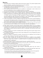
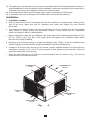
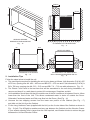
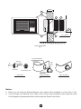
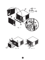
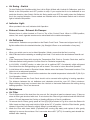
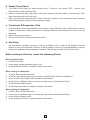
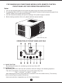
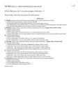
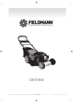
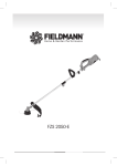
Taurus Series YORK Window Air Conditioners IOM IOWRCAG50220711A1 Warning 1. Before using the Air conditioner please read the instructions carefully. They contain important advise about the installation, operation & maintenance of your Air conditioner. 2. Please keep this manual in a safe place for future user. 3. The Manufacturer cannot be held responsible for any injury or damage to person, animals or property if the following has not been observed. 4. After unpacking, please make sure that the Air conditioner is undamaged. In case of doubt, do not use the Air conditioner but call for a qualified technician or your dealer. 5. Only use the Air conditioner for its intended purpose, that is Room Air conditioning. 6. Installation must be carried out by a qualified technician, following the manufacturer’s instruction. 7. Before connecting the Air conditioner, please make sure that the data shown on the rating plate correspond to those of your place of installation. Electrical safety is ensured only if the Air conditioner is correctly earthed as prescribed by safety standards for electrical installations. It is imperative that this fundamental safety requirement be checked. In case of doubt, careful inspection of the wiring at the installation must be carried out by a qualified Electrician. 8. As the running ampere of the Air conditioner is larger than that of the other household appliances, you must also check that the section of wiring of the outlet where you have planned to connect the Air conditioner can withstand the power absorbed by the Air conditioner, Which is stated on the rating plate. In case of doubt, please contact a qualified technician. 9. The outlet used for connecting the Air conditioner should have a 30A Time delay Fuse and must be used exclusively for the Air conditioner. Don’t use the same outlet with other appliance. 10. Power supply connection must be made as per the wiring diagram affixed on the Air conditioner. 11. If a Plug has to be used, then the wall socket & Plug must with stand the power requirements of the Air conditioner and in compliance with Iocal safety regulations and should comply with IEC 60083. The use of adapters, multiple sockets and extension cords is not advisable. Ensure that the Power Plug is properly Pluged in. 12. If the Air conditioner is not used for extended periods, please keep the main power supply to the Air conditioner switch OFF. 13. Air conditioners with Mechanical type controls, when switched OFF, must be Restarted only after 3 minutes for safety reasons. 14. Before any cleaning or maintenance operation, disconnect the Air conditioner from the mains by switching off the electricity at the mains or by pulling out the plug. 15. For any repair, servicing, call the dealer from whom the Air conditioner was purchased. 16. When you notice any abnormality (smell of burning, etc.) stop the Air conditioner and switch OFF the Main Power supply. Call your dealer or a qualified Technician to investigate the Cause and to make necessary repair or maintenance. 17. Repair and relocation of the Air conditioner should be done by a qualified Technician. 18. Do not clean the Air conditioner by yourself with a wet cloth, water or any other liquid, except those mentioned under maintenance section. 19. Do not spray on the Air conditioner with insecticides or flammable sprays. 20. Do not expose the skin directly to the cool air for long periods of time. 21. Do not install the Air conditioner where leakage of inflammable gases may occur and/or in an Explosive atmosphere. 22. When using the Air conditioner or any electrical appliance, you must follow these basic safety rules : - do not touch or operate the Air conditioner with wet hands or when barefoot. - do not pull the cable to unplug when connected to the wall socket with a plug, but the plug itself. - do not operate or stop the unit by inserting or pulling out the power plug. - do not allow the Air conditioner to be operated by young children without surveillance. 1 23. This appliance is not intended for use by person (including children) with reduced physical, sensory or mettal capabilities or lack of expereince and knowledge. Unless they have been given supervison or instruction concerning use of appliance when it is put into operation. 24. A disconnection provision form the supply mains must be incorporated in fixed wiring. 25. In case the power cord is damaged. Use suitable cable advised the manufacturer. Installation 1. Installation Location a Select a place where Cool Air discharged from the Air conditioner circulates evenly, reaching every part of the room. Make sure that no obstacles both inside and outside the room prevent the Air flow. b The outdoor side where the Sun light does not fall directly on the Air conditioner is the most suitable place (North or East). Where not practicable provide a hood above the Air Conditioner when it is installed in South or West direction. c Where practicable, locate the air conditioner with lower edge of the Cabinet approximately 0.76 m (30”) to 1.525 m (60”) from floor. This usually gives the optimum air circulation pattern within the room for Cooling & Heating. d Mounting must be strong enough to support the Weight ( Max. 100kg ) of the Air conditioner with sufficient rigidity to prevent vibration being transmitted to the windows and the like. e Condensor Air inlet Louvers should not be covered, provide sufficient clearance all around the Air conditioner as shown in Fig - C & D. To ensure proper air flow, atleast any two rear side of the unit should be perpetually open.(see fig.) f When the wall thickness is over 200 mm, provide bevelled sides as shown in Fig - E to remove obstructions to the Condenser inlet Air. CONDENSER AIR INLET CONDENSER AIR OUTLET ROOM AIR INLET CONDENSER AIR INLET CONDITIONED AIR OUTLET Fig. - A 2 200mm AA 90 cm Min. BB WINDOW OPENING DIMENSION FOR MOUNTING Fig. - B CLEARANCE AT THE REAR SIDE Fig. - C 50 cm 50cm OVER 200 mm 200mm 200mm BEVELLED SIDES CLEARANCE AT THE SIDES WHEN WALL THICKNESS EXCEEDS 200 mm. Fig. - E CLEARANCE AT THE SIDES Fig. - D 2. Installation Tips Follow the steps below to Install the unit. a The opening size required for installing the unit is to be down as follows: Unit dimension (D X W): 455 x 670 mm, opening size AA: 458 ~ 460 mm and BB: 673 ~ 675 mm and if Unit dimension (D X W) is b c d e 510 x 708 mm, opening size AA: 513 ~ 515 mm and BB: 711 ~ 713 mm with reference to Fig. - B. The Plastic Front Panel is the last Item that will be assembled to the unit during Installation, so remove and keep it in a safe place to protect it from damages, Scratches and dirt. Unit installation should be such that, the outside rear of the Air conditioner Is between 5mm to 10mm lower than the front of the Unit. This allows condensed water to drain off outside the Room. Otherwise Condensed water and Rain may flow Into the Room. (See Fig. - H) Unscrew the two shipping screws from the lower rear portion of the Cabinet (See Fig. - F) and slide out the Unit from the Cabinet. Fix the Long Urethane Foam (supplied with the Unit) on the 3 outer sides of the Cabinet as shown in Fig. - G (Left, Top & Right) to weather seal any gap between the Cabinet and the Wooden Frame. If your window opening size is larger than the one required, use Wooden blocks to reduce the gap between the Unit and Wooden Frame. 3 f The Cabinet should be secured to the Wooden Frame In order to prevent the Unit from falling down. Holes are provided on the Left, Right & Bottom sides of the Cabinet (See Fig. - G) for fixing it to the Wooden Frame. Choose a side of the Wooden Frame which is right angle to the bottom surface to fix the Cabinet and use Nails or Screws (Not supplied) for fixing it. If required, provide two Brackets (Not supplied) on the rear side to support the Unit. g If required, fix an Ornamental Frame (Not supplied) around the Cabinet on the Room side to cover the Gaps between the Cabinet and the Wooden Frame as shown in Fig. - H. h Fix the Drain tube to the Rectangular opening provided on the Lower left portion on the rear side of the Unit. The orientation of the Drain Tube should be as shown In Fig. - I to maintain sufficient Condensed water level in the Base Tray for splashing Water on the Condenser Coil. i Push the Unit completely back into the Cabinet fitted in the Window. j Weather seal the openings on the Front Bottom portion (Between the Cabinet inner surface and the unit) with the Urethane Foam provided with the unit. (See Fig. - J) k Fix the Front Panel to the Cabinet by hooking the two Stoppers provided on the Top under side of the Front Panel to the Rectangular slots provided on the Top side of the Cabinet (See Fig. - J), Flush fit the Front Panel to the Cabinet and fix one each Screw (Supplied) from both sides of the Front Panel to Cabinet. l Complete the installation by connecting the Power Supply Cord. Ensure that all wire connections are tightend & secure No. Description 1 Wall 2 3 4 5 6 7 8 8a 8b Wooden Frame Cabinet Bracket, Cabinet Support (2 pcs.) Urethane Foam (Cabinet outside) Ornamental Frame Drain Tube Plastic Front Panel Return Air Grille Insert Horizontal Deflectors (Hori. Louvers) 8c Air Filter No. 8d 8e 9 10 11 12 13 14 15 16 Description Cover - Control Panel Air Filter - Special Unit Urethane Foam (Front Bottom) Control Panel Indicator Light Air Swing switch (Vertical Air deflector) Knob - Operation / Mode Switch Knob - Temperature Setting Thermostat Vertical Air Deflector (Vert. Louver) 17a Exhaust Damper Lever (Front) 17b Exhaust Damper Lever (Top) Shipp Fig. - ing Sc rews Holes for fixing Nails or Screws F Fig. - G 4 200mm 1 6 5 3 7 2 4 5 to 10 mm TYPICAL INSTALLATION Fig - H Rectangular Opening Base Tray Top Side To Base Tray Top Side Drain Outlet Side View View Drain Outlet Side Drain Tube Drain Tube Before Assembly After Assembly Fig - 1 Notes : a. Either one out of the two Exhaust Damper Lever option will be available in a Unit (17a or 17b). b. If you find type 17b Exhaust Lever (Top) In the unit you have purchased, then unfold the Lever from Shipped to Operational position, before fixing the Plastic Front Panel. 5 SHIPPED POSITION 3 17b OPERATIONAL POSITION Fig - J 8 8a (U) 8b (D) [A] 8e [L] [B] 8d 8c [F] Fig. - M [C] 6 Fig. - N 3. Operation Instruction Control Panel is located at the Lower Right bottom of the Air conditioner. Units with and without Control Panel Cover are available. To access a Control Panel with Cover, Press at Point [C] marked with "PUSH" to unlock the Control Panel Cover and move it from DOWN "D" position to UP "U" position for locking it. Gently Push it back to close the cover. Open Close Exhaust OFF HI FAN LO FAN HI COOL LO COOL OFF COOLER MED COOL ON TEMPERATURE OPERATION Air Swing CONTROL PANEL - COOL MODELS FIG. - K Open Close Exhaust OFF LO FAN OFF MED LO HEAT WARMER HI HEAT COOLER HI ON TEMPERATURE Air Swing OPERATION CONTROL PANEL - HEAT MODELS (HEAT PUMP & ELECTRICAL HEATER MODELS) FIG. - L Table - 1 Operation / Mode Desired Operation To Cool or Heat To Exhaust Room Air in Cool or Heat Mode Exhaust Lever LO-COOL, MED-COOL, HI-COOL LOW HEAT, HI- HEAT To Circulate and Filter Room Air To Exhaust Room Air with odours To Stop Operation Close Open LO-FAN, HI-FAN or FAN Close OFF Close Open Temperature Dial Set dial to the Desired Location in the COOLER/ WARMER scale for COOL / HEAT operation respectively Air Swing Switch ON or OFF Any Position OFF a OPERATION / MODE - Switch Rotate the Knob either in Clock or Counter Clock wise direction to select the required OPERATION / MODE. b TEMPERATURE - Switch Rotate the Knob to the required position in the scale (Cooler in Cool Model and Cooler or Warmer in Heat Models) to select the required Temperature setting. 7 c Air Swing - Switch To Auto Deflect the Conditioned Air from Left to Right & Back with Vertical Air Deflectors, push the Switch to the ON position and OFF position to stop. If you require the Air to be deflected to one particular direction, then Switch ON the Air Swing switch and OFF the switch when the Deflectors are in the required direction. Some models are Installed with an illuminated Switch and It will emit light to indicate ON position. d Indicator Light. When provided in the unit, indicates Unit Operation. e Exhaust Lever - Exhaust Air Damper. Exhaust Lever is either Iocated on Front or Top of the Control Panel. When in OPEN position, odours, foul smell, cigarette smoke can be exhausted to the outside atmosphere. f Air Deflectors Horizontal Air Deflectors are provided on the Plastic Front Panel. These can be lipped as in [L] of fig M to deflect Air to the desired direction (Up, Straight & Down or a combination of any two). Notes : 1 When you switch over to cool or Heat Operation / Mode, ensure that the fan is running. 2 Wait 3 Minutes before restarting or resetting from Heat / Cool mode to fan and between heat & cool mode 3 If the Compressor Stops while turning the Temperature Dial, Clock or Counter Clock wise, wait for 3 Minutes before turning back to Counter Clock or Clockwise respectively. 4 In LO-COOL, LO-HEAT modes, or when the unit is switched OFF, Occasionally slight refrigerant Flow Noise from the Refrigerating cycle will be heard. This noise is not an Abnormal operation. 5 A click Noise will be heard in Electrical Heater Models when the Heater Thermostat functions. This Noise is not an abnormal operation. 6 This room air conditioner should not be used when the outside temperature is below 680 F (200 C) in Cool Operation / Mode. 7 The air deflectors and the Front Panel should not be covered with anything in heating operation. The distance between the air deflectors and obstacles should be over 20” (50cm) minimum. 8 Slight rubbing sound may be heard when the Vertical or Horizontal Deflectors are moving during heating operation. This is not abnormal. 4 Maintenance a Air Filter 1 2 3 The Air filters most of the dust from the room air, So it should at least be cleaned every 15 days or when air filter gets shocked with dust. If not cleaned the Filter will get chocked and the Airflow will reduce. This will decrease the Cooling or Heating efficiency of the Air conditioner. To remove the Air Filters, gently press at Point [A] & [B] as shown in Fig. N to unlock the Return Air Grille Insert and then open and hold the Grills at the UP “U” position. Hold the Filter Handle, gently release it from the Front Panel by slightly lifting it up and taking it out. Wash the Filter with clean Water (if possible with running tap water) and replace it after gently shaking it to remove the moisture. Don’t use water above 95 F (350 C) for washing and reinstall the airfilters after cleaning 8 b. Plastic Front Panel 1 The Plastic Front Panel can easily become dirty. To clean it, shut power *OFF*, remove Front Panel & Wipe it with a soft dry cloth. 2 When it is extremely dirty, wipe with a soft cloth containing lukewarm water or neutral soap. Then wipe thoroughly with a soft dry cloth. Never use hot water more than 95 F (35 C), Benzene, gasoline, acid, thinner and brush, because these will damage the Plastic Surface and the coating. 3 c. Condenser & Evaporator Coils 1 Coils should be cleaned periodically to have better cooling efficiency. Use a soft brush or vacuum cleaner to clean them, make sure that the Condenser Rear and the Evaporator Front Fins are not damaged. 2 Steam cleaning can be done. 3. Do not touch the fins of the coil with bare hands d. Servicing We recommend complete servicing of the Air conditioner prior to start of the Season (Summer season in case of Cool Models, Summer & Winter season in case of Cool/Heat Models) to ensure trouble free operation during respective seasons. This will also increase the Life of the Unit. Before asking for Service, check the following Points When operation fails : 1 Is the fuse all right? 2 Is the supply voltage extremely high or low? 3 Is the temperature dial in a suitable location in the scale? When cooling is inadequate : 1 2 Is the Air filter chocked with dust? Is the Sun light directly falling on the outdoor rear side of the Room Air conditioner? 3 4 5 Is the air flow of the outdoor side (condenser) obstructed? Are the Doors, Windows open or is there any other source of heat in the Room? Is the Exhaust Damper open? 6 Is the temperature dial in a suitable location in the scale? When heating is inadequate : 1 2 3 Is the Air filter chocked with dust? Are the Doors, Windows open or is there any other source of heat in the Room? Is the Exhaust Damper open? 4 Is the temperature dial in a suitable location in the scale? 9 FOR WINDOW AIR CONDITIONER MODELS WITH REMOTE CONTROL FRONT PANEL KEY PAD OPERATION INSTRUCTION Notes 1. Unit can be operated either the front panel key pad Or from the remote control handset. 2. For switching ON or OFF the unit, always use the ON/OFF button of the front panel key pad Or the ON/OFF button of the remote control handset. 3. Unit will restart automatically with previous settings, If the power supply is restored. 4. Before starting operation of the unit, please read this manual carefully. Front Panel Key Pad OPERATION OF FRONT PANEL KEY PAD A. ON/OFF BUTTON - By pressing this button, Air conditioning until will turn ON or OFF. B. MODE BUTTON - By pressing this button each time the operation mode will change in the following sequence. - This will be indicated by the LED lights on the Control Panel Key Pad. FAN COOL *HEAT FAN - After selecting the modes, each mode will be recorded in the non-volatile memory. This memory will be read during every power ON start up. * Heat mode selection is applicable only for Cool & Heat Models. l l l 10 C. FAN BUTTON - By pressing this button each time the fan speed will change in the following sequence. - This will be indicated by the LED lights on the Control Panel Key Pad. LOW MED HIGH AUTO LOW - There is no AUTO fan speed available in FAN mode. D. SWING BUTTON - Press this button to run on swing mode. - Press it again to stop the louver in the preferred air distribution location. E. TEMPERATURE UP & DOWN BUTTONS - Each Press of these button will increase or decrease the set temperature by 1°C. - The range of set temperature is 16°C - 30°C. - Temperature setting is disabled in FAN mode. F TIMER BUTTON - ON Timer can only be set when the system is OFF. - OFF Timer can only be set when system is ON. - Pressing of ‘ON’ or ‘OFF’ button will display the previous timer. - Press UP or DOWN button to set the desired new timer. - The range of timer is 0-24 hours. - After time mode is set, TIMER LED light will be ON. - Air conditioning until will turn ON or OFF automatically when the set number of hour have elapsed. - Changing of ON/OFF state will cancel TIMER mode. - Timer will cancel during power failure. G 7. SEGMENT DISPLAY - This display will show Room temperature during normal working. - This display will show Set temperature when setting the temperature. - This display will show Timer when setting the Timer. - The following are various error diagnostic indications displayed on the 7 segment display. INDICATION FAULT CONDITION Room temperature sensor failure E1 on Display Indoor Coil Sensor Failure E2 on Display Outdoor coil sensor failure (For Heat pump) E3 on Display Compressor / 4WV failure (For Heat pump) E4 on Display H OPERATION MODE DISPLAY - Shows the selected operation mode Cool, Fan Or *Heat. - Following are the other indications available for the protections. PROTECTIONS INDICATION Indoor coil frost prevention COOL LED blinks continuously Outdoor auto defrost (For Heat pump) HEAT LED blinks continuously 11 I. FAN SPEED DISPLAY - Show the selected Fan speed Auto, Low, Med Or High. J. IR SIGNAL RECEIVER - Receives signals from the infrared transmitter. - Don’t close this opening with any hard object since it will object the proper reception of signals from the transmitter. K. SLEEP - Pressing the SLEEP button will ON or OFF the energy saving SLEEP function. - SLEEP function is not available in FAN mode. - In Cool or Heat mode, SLEEP function will automatically adjust the set temperature to provide comfortable sleeping condition. REMOTE CONTROL - USER MANUAL FOR COOL / HEAT MODELS 12 OPERATION 1. TRANSMISSION SOURCE - Before starting the operation from the handset, keep the handset’s transmission source at line of sight with the signal receiver 2. ON/OF - Each press off this button will turn ON or OFF the unit. - On every press, ON/OFF status will be indicated by the displays at the receiver side. 3. MODE - Pressing the MODE button will select the Cool Mode operation, Fan Mode operation and the Heat mode operation. - Sequence will be as follows: FAN HEAT COOL - Selected mode will be indicated at the receiver. NOTE : In cool only unit, heat mode selection will not be available. 4. FAN - Pressing this button will advance the fan speed in the following sequence: LOW MEDIUM HIGH AUTO - Under FAN mode, only LOW MEDIUM HIGH sequence will be available. 5. TIMER - TIMER function is to turn the unit ON or OFF automatically after a certain number of hours. - Pressing TIMER button once will show the time left for the unit to turn ON or OFF. - Subsequent pressing of TIMER button will increase the timer setting in 1 hour step from 1 to 15 hours. - If TIMER key is not pressed for 5s continuously, the display return to temperature display. NOTE : TIMER set range will vary for model to model 6. SLEEP - Pressing the SLEEP button will ON or OFF the energy saving SLEEP function. - SLEEP function is not available in FAN mode. - In cool or heat mode, SLEEP function will automatically adjust the set temperature to provide comfortable sleeping condition. 7. SWING (OPTIONAL) - Pressing the SWING button will activate or deactivate the air swing operation. 8,9 TEMPERATURE SETTING and buttons are used to set the temperature . - Press button to increase the set temperature by 1°C. - Press button to decrease the set temperature by 1°C. - Set temperature available from 16°C to 30°C. - Temperature setting will be disabled in FAN mode. NOTE : For some models, during TIMER setting mode, these same buttons will be used to set the timer also. 13