1
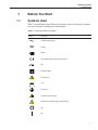
7320
Calibration Bath
User’s Guide
PN 3720888
February 2013
© 2013 Fluke Corporation. All rights reserved. Specifications are subject to change without notice.
All product names are trademarks of their respective companies.
Table of Contents
1 Before You Start . . . . . . . . . . . . . . . . . . . . . . . . . . 1
1.1
Symbols Used . . . . . . . . . . . . . . . . . . . . . . . . . . . . 1
1.2
Safety Information . . . . . . . . . . . . . . . . . . . . . . . . . . 2
1.2.1
1.2.2
1.3
Warnings . . . . . . . . . . . . . . . . . . . . . . . . . . . . . . . . . . . . . 2
Cautions . . . . . . . . . . . . . . . . . . . . . . . . . . . . . . . . . . . . . 4
Authorized Service Centers. . . . . . . . . . . . . . . . . . . . . . 5
2 Introduction . . . . . . . . . . . . . . . . . . . . . . . . . . . . 9
3 Specifications and Environmental Conditions . . . . . . . . . 11
3.1
3.2
Specifications . . . . . . . . . . . . . . . . . . . . . . . . . . . . 11
Environmental Conditions. . . . . . . . . . . . . . . . . . . . . . 12
3.3
Warranty . . . . . . . . . . . . . . . . . . . . . . . . . . . . . . . 12
4 Quick Start . . . . . . . . . . . . . . . . . . . . . . . . . . . . 13
4.1
4.2
4.3
Unpacking . . . . . . . . . . . . . . . . . . . . . . . . . . . . . . 13
Set Up . . . . . . . . . . . . . . . . . . . . . . . . . . . . . . . . 13
Power . . . . . . . . . . . . . . . . . . . . . . . . . . . . . . . . 14
4.4
Setting the Temperature . . . . . . . . . . . . . . . . . . . . . . . 14
5 Bath Use . . . . . . . . . . . . . . . . . . . . . . . . . . . . . . 17
5.1
5.2
5.3
General . . . . . . . . . . . . . . . . . . . . . . . . . . . . . . . 17
Comparison Calibration . . . . . . . . . . . . . . . . . . . . . . . 17
Calibration of Multiple Probes . . . . . . . . . . . . . . . . . . . 18
6 Calibration Procedure . . . . . . . . . . . . . . . . . . . . . . 19
6.1
6.2
6.3
6.4
Calibration Points . . . . . . .
Measuring the Set-point Error.
Computing R0 and ALPHA . .
Calibration Example. . . . . .
.
.
.
.
.
.
.
.
.
.
.
.
.
.
.
.
.
.
.
.
.
.
.
.
.
.
.
.
.
.
.
.
.
.
.
.
.
.
.
.
.
.
.
.
.
.
.
.
.
.
.
.
.
.
.
.
.
.
.
.
.
.
.
.
.
.
.
.
.
.
.
.
.
.
.
.
19
19
19
20
7 Charging Instructions . . . . . . . . . . . . . . . . . . . . . . 23
7.1
7.2
7.3
Leak Testing . . . . . . . . . . . . . . . . . . . . . . . . . . . . . 23
Evacuation. . . . . . . . . . . . . . . . . . . . . . . . . . . . . . 23
Charging. . . . . . . . . . . . . . . . . . . . . . . . . . . . . . . 23
i
8 Maintenance . . . . . . . . . . . . . . . . . . . . . . . . . . . 25
8.1
General . . . . . . . . . . . . . . . . . . . . . . . . . . . . . . . 25
9 Troubleshooting. . . . . . . . . . . . . . . . . . . . . . . . . . 27
9.1
Troubleshooting . . . . . . . . . . . . . . . . . . . . . . . . . . . 27
9.2
Comments . . . . . . . . . . . . . . . . . . . . . . . . . . . . . . 29
9.2.1
9.2.2
ii
EMC Directive . . . . . . . . . . . . . . . . . . . . . . . . . . . . . . . . . 29
Low Voltage Directive (Safety) . . . . . . . . . . . . . . . . . . . . . . . . . 30
Figures
Figure 1
Calibration Example . . . . . . . . . . . . . . . . . . . . . . . . . . . 21
iii
Tables
Table 1
iv
International Electrical Symbols . . . . . . . . . . . . . . . . . . . . . 1
1 Before You Start
Symbols Used
1
1.1
Before You Start
Symbols Used
Table 1 lists the International Electrical Symbols. Some or all of these symbols
may be used on the instrument or in this manual.
Table 1 International Electrical Symbols
Symbol
Description
AC (Alternating Current)
AC-DC
Battery
CE Complies with European Union Directives
DC
Double Insulated
Electric Shock
Fuse
PE Ground
Hot Surface (Burn Hazard)
Read the User’s Manual (Important Information)
Off
On
1
User’s Guide
Symbol
Description
Canadian Standards Association
OVERVOLTAGE (Installation) CATEGORY II, Pollution Degree 2 per IEC1010-1 refers to the level of Impulse Withstand Voltage protection provided. Equipment of
OVERVOLTAGE CATEGORY II is energy-consuming equipment to be supplied from
the fixed installation. Examples include household, office, and laboratory appliances.
C-TIC Australian EMC Mark
The European Waste Electrical and Electronic Equipment (WEEE) Directive
(2002/96/EC) mark.
1.2
Safety Information
Use this instrument only as specified in this manual. Otherwise, the protection
provided by the instrument may be impaired.
The following definitions apply to the terms “Warning” and “Caution”.
• “Warning” identifies conditions and actions that may pose hazards to the
user.
• “Caution” identifies conditions and actions that may damage the instrument being used.
1.2.1
Warnings
To avoid personal injury, follow these guidelines.
GENERAL
• DO NOT use the instrument for any application other than calibration
work. The instrument was designed for temperature calibration. Any other
use of the unit may cause unknown hazards to the user.
• DO NOT use the unit in environments other than those listed in the user’s
guide.
• DO NOT overfill the bath. Overflowing extremely cold or hot fluid may
be harmful to the operator. See Section 5.3, Bath Preparation and Filling,
for specific instructions.
• Follow all safety guidelines listed in the user’s manual.
• Calibration Equipment should only be used by Trained Personnel.
• If this equipment is used in a manner not specified by the manufacturer,
the protection provided by the equipment may be impaired.
• Before initial use, or after transport, or after storage in humid or semi-humid environments, or anytime the instrument has not been energized for
more than 10 days, the instrument needs to be energized for a "dry-out"
2
1 Before You Start
Safety Information
period of 2 hours before it can be assumed to meet all of the safety requirements of the IEC 1010-1. If the product is wet or has been in a wet
environment, take necessary measures to remove moisture prior to applying power such as storage in a low humidity temperature chamber operating at 50 degree centigrade for 4 hours or more.
• DO NOT operate high temperature baths (500°C) near flammable materials. Extreme temperatures could ignite the flammable material.
• Overhead clearance is required. Do not place the instrument under a cabinet or other structure. Always leave enough clearance to allow for safe
and easy insertion and removal of probes.
• The instrument is intended for indoor use only.
BURN HAZARD
• Extremely cold temperatures may be present in this equipment. Freezer
burns and frostbite may result if personnel fail to observe safety precautions.
• High temperatures may be present in this equipment. Fires and severe
burns may result if personnel fail to observe safety precautions.
ELECTRICAL HAZARD
• These guidelines must be followed to ensure that the safety mechanisms
in this instrument will operate properly. This instrument must be plugged
into a 115 VAC, 60Hz (230 VAC, 50Hz optional), AC only electric outlet.
The power cord of the instrument is equipped with a three-pronged
grounding plug for your protection against electrical shock hazards. It
must be plugged directly into a properly grounded three-prong receptacle.
The receptacle must be installed in accordance with local codes and ordinances. Consult a qualified electrician. DO NOT use an extension cord or
adapter plug.
• DO use a ground fault interrupt device. This unit contains a liquid. A
ground fault device is advised in case liquid is present in the electrical
system and could cause an electrical shock.
• Always replace the power cord with an approved cord of the correct rating and type. If you have questions, contact an Authorized Service Center
(see Section 1.3).
• High voltage is used in the operation of this equipment. Severe injury or
death may result if personnel fail to observe the safety precautions. Before
working inside the equipment, turn off the power and disconnect the
power cord.
BATH FLUIDS
• Fluids used in this unit may produce noxious or toxic fumes under certain
circumstances. Consult the fluid manufacturer’s MSDS (Material Safety
Data Sheet). Proper ventilation and safety precautions must be observed.
3
User’s Guide
• The unit is equipped with a soft cutout (user settable firmware) and a hard
cutout (set at the factory). Check the flash point, boiling point, or other
fluid characteristic applicable to the circumstances of the unit operation.
Ensure that the soft cutout is adjusted to the fluid characteristics of the application.
1.2.2
Cautions
To avoid possible damage to the instrument, follow these guidelines.
• THE DRAIN VALVE MUST BE INSTALLED ON THE BACK OF
THE BATH BEFORE ATTEMPTING TO FILL THE TANK WITH
FLUID. See Section 5.3, page 17 for drain installation instructions.
• Always operate this instrument at room temperature between 41°F and
104°F (5°C to 40°C). Allow sufficient air circulation by leaving at least 6
inches (15 cm) of clearance around the instrument.
• DO NOT overfill the bath. Overflowing liquid may damage the electrical
system. Be sure to allow for thermal expansion of the fluid as the bath
temperature increases. See Section 5.3, Bath Preparation and Filling, for
specific instructions.
• Read Section 5, 6, Bath Use, before placing the unit into service.
• DO NOT change the values of the bath calibration constants from the factory set values. The correct setting of these parameters is important to the
safety and proper operation of the unit.
• The refrigeration may be damaged or the lifetime shortened if the
set-point temperature is set above 60°C for more than one hour with the
refrigeration manually on. Ensure that the refrigeration is off when the
unit is used above 60°C.
• The Factory Reset Sequence should be performed only by authorized
personnel if no other action is successful in correcting a malfunction. You
must have a copy of the most recent Report of Test to restore the test parameters.
• DO NOT operate this instrument in an excessively wet, oily, dusty, or
dirty environment.
• The unit is a precision instrument. Although it has been designed for optimum durability and trouble free operation, it must be handled with care.
Position the unit before the tank is filled with fluid. Use the handles provided to move the unit. Due to the weight of the compressor, it may require two people to safely move the bath. If two people are used, place
one person in the front and one person in the back of the unit, carefully
slide hands under the unit and lift in unison. The area containing the compressor is heavier than the rest of the unit. Do not move a unit filled with
fluid.
• Most probes have handle temperature limits. Be sure that the probe handle
temperature limit is not exceeded in the air above the instrument.
4
1 Before You Start
Authorized Service Centers
• The instrument and any thermometer probes used with it are sensitive instruments that can be easily damaged. Always handle these devices with
care. Do not allow them to be dropped, struck, stressed, or overheated.
COLD BATHS
• Refrigerated baths require that the condensing coil be cleaned periodically. Accumulation of dust and dirt on the condenser will result in premature failure of the compressor.
• This bath has been equipped with a brownout and over voltage protection
device as a safety feature to protect the system components.
• Mode of Operation: This bath needs to be plugged into the line voltage
for at least 2 minutes before operation. This is only necessary for the first
time that the bath is energized or when it is moved from one location to
another. Turning the bath ON or OFF does not trigger the delay.
• If a High/Low voltage condition exists for longer than 5 seconds, the bath
de-energizes. An amber indicator on the back panel lights when this condition exists.
• Re-energization is automatic upon correction of the fault condition and after a delay cycle of about 2 minutes. If a fault condition exists upon application of power, the bath will not energize.
• Under and Over Voltage Protection at 115 VAC
♦
Voltage Cutout: ±12.5% (101 - 129 VAC)
♦
Voltage Cut In: ±7.5% (106 - 124 VAC)
• Under and Over Voltage Protection at 230 VAC
1.3
♦
Voltage Cutout: ±12.5% (203 - 257 VAC)
♦
Voltage Cut In: ±7.5% (213 - 247 VAC)
Authorized Service Centers
Please contact one of the following authorized Service Centers to coordinate
service on your Hart product:
Fluke Corporation, Hart Scientific Division
799 E. Utah Valley Drive
American Fork, UT 84003-9775
USA
Phone: +1.801.763.1600
Telefax: +1.801.763.1010
E-mail: [email protected]
5
User’s Guide
Fluke Nederland B.V.
Customer Support Services
Science Park Eindhoven 5108
5692 EC Son
NETHERLANDS
Phone: +31-402-675300
Telefax: +31-402-675321
E-mail: [email protected]
Fluke Int'l Corporation
Service Center - Instrimpex
Room 2301 Sciteck Tower
22 Jianguomenwai Dajie
Chao Yang District
Beijing 100004, PRC
CHINA
Phone: +86-10-6-512-3436
Telefax: +86-10-6-512-3437
E-mail: [email protected]
Fluke South East Asia Pte Ltd.
Fluke ASEAN Regional Office
Service Center
60 Alexandra Terrace #03-16
The Comtech (Lobby D)
118502
SINGAPORE
Phone: +65 6799-5588
Telefax: +65 6799-5588
E-mail: [email protected]
When contacting these Service Centers for support, please have the following
information available:
• Model Number
• Serial Number
6
1 Before You Start
Authorized Service Centers
• Voltage
• Complete description of the problem
7
2 Introduction
2
Introduction
The Hart Scientific 7320 is a bench-top constant temperature bath useful in
temperature calibration and other applications requiring stable temperatures.
An innovative state of the art solid-state temperature controller has been incorporated which maintains the bath temperature with extreme stability. The temperature controller uses a micro-controller to execute the many operating
functions.
User interface is provided by the 8-digit LED display and four key-switches.
Digital remote communications is standard with an RS-232 and optional with
an IEEE-488 interface.
The 7320 bath was designed to be compact and low cost without compromising
performance. The 7320 bath operates over a wide temperature range from
–20°C to 150°C. The refrigeration permits sub-ambient temperature control.
9
3 Specifications and Environmental Conditions
Specifications
3
3.1
Specifications and Environmental
Conditions
Specifications
Range
–20°C to 150°C
Stability (2 sigma)
±0.005°C at –20°C (ethanol)
±0.005°C at 25°C (water)
±0.007°C at 150°C (silicone oil 5012)
Uniformity
±0.005°C at –20°C (ethanol)
±0.005°C at 25°C (water)
±0.010°C at 150°C (silicone oil 5012)
Heating Time
†
80 minutes, from 25°C to 150°C (silicone oil 5012)
Cooling Time
100 minutes, from 25°C to –20°C (silicone oil 5012)
Stabilization Time
15-20 minutes
Temperature Setting
Digital display with push-button entry
Set-point Resolution
0.01°; 0.00018° in high resolution
Display Temperature Resolution 0.01°
Digital Setting Accuracy
±0.5°C
Digital Setting Repeatability
±0.01°C
Heater
650 Watts
Access Opening
6.8” x 3.7” (172mm x 94mm)
Depth
9.25” (234 mm)
Wetted Parts
304 Stainless Steel
Power
115 VAC (±10%), 60 Hz, 15 amps [230 VAC (±10%), 50 Hz, 8 amps
optional], 1100 W
†
Note: If the voltage is outside ±10%, the compressor may be
damaged. Check the back panel label for the correct voltage and frequency prior to energizing the unit.
Volume
2.4 gal. (9.2 liters)
Weight
78 lb. (35.4 kg)
Size
12” x 24.5” x 23” (305 mm x 622 mm x 584 mm)
Safety
OVERVOLTAGE (Installation) CATEGORY II, Pollution Degree 2 per
IEC 1010-1
Cooling Capacity
600 BTU/h
Refrigeration
R-507 single stage
Interface Package
RS-232 included, IEEE-488 optional
Rated at listed 115 V (or optional 230 V)
†
11
User’s Guide
3.2
Environmental Conditions
Although the instrument has been designed for optimum durability and trouble-free operation, it must be handled with care. The instrument should not be
operated in an excessively dusty or dirty environment. Maintenance and cleaning recommendations can be found in the Maintenance Section of this manual.
The instrument operates safely under the following conditions:
• temperature range: 5–40°C (41–104°F)
• ambient relative humidity: maximum 80% for temperatures < 31°C decreasing linearly to 50% at 40°C
• pressure: 75kPa - 106kPa
• mains voltage within ±10% of nominal
• vibrations in the calibration environment should be minimized
• altitudes less than 2000 meters
• indoor use only
3.3
Warranty
Fluke Corporation, Hart Scientific Division (Hart) warrants this product to be
free from defects in material and workmanship under normal use and service
for a period as stated in our current product catalog from the date of shipment.
This warranty extends only to the original purchaser and shall not apply to any
product, which, in Hart’s sole opinion, has been subject to misuse, alteration,
abuse or abnormal conditions of operation or handling.
Software is warranted to operate in accordance with its programmed instructions on appropriate Hart products. It is not warranted to be error free.
Hart’s obligation under this warranty is limited to repair or replacement of a
product, which is returned to Hart within the warranty period and is determined, upon examination by Hart, to be defective. If Hart determines that the
defect or malfunction has been caused by misuse, alteration, abuse or abnormal
conditions or operation or handling, Hart will repair the product and bill the
purchaser for the reasonable cost of repair.
To exercise this warranty, the purchaser must forward the product after calling
or writing an Authorized Service Center (see Section 1.3) for authorization.
The Service Center assumes NO risk for in-transit damage.
THE FOREGOING WARRANTY IS PURCHASER’S SOLE AND EXCLUSIVE REMEDY AND IS IN LIEU OF ALL OTHER WARRANTIES, EXPRESS OR IMPLIED, INCLUDING BUT NOT LIMITED TO ANY
IMPLIED WARRANTY OR MERCHANTABILITY, OR FITNESS FOR ANY
PARTICULAR PURPOSE OR USE. HART SHALL NOT BE LIABLE FOR
ANY SPECIAL, INDIRECT, INCIDENTAL, OR CONSEQUENTIAL DAMAGES OR LOSS WHETHER IN CONTRACT, TORT, OR OTHERWISE.
12
4 Quick Start
Unpacking
4
Quick Start
CAUTION: Read Section 5, 6 entitled BATH USE before placing the bath
in service.
This chapter gives a brief summary of the steps required to set up and operate
the bath. This should be used as a general overview and reference and not as a
substitute for the remainder of the manual. Please read Section 5, Installation,
through Section 8, General Operation, carefully before operating the bath.
4.1
Unpacking
Unpack the bath carefully and inspect it for any damage that may have occurred during shipment. If there is shipping damage, notify the carrier immediately. Verify that all components are present:
• 7320 Bath
• RS-232 Cable
• Access Hole Cover
• Drain Valve
• Manual
• Report of Test
If you are missing any item, please call a Hart Authorized Service Center (see
Section 1.3).
4.2
Set Up
CAUTION: The drain valve must be installed on the back of the bath before attempting to fill the tank with fluid. See Section 5.3, on page 17 for
drain installation instructions.
WARNING: The instrument is equipped with a soft cutout (user settable
firmware) and a hard cutout (set at the factory). Check the flash point,
boiling point, or other fluid characteristic applicable to the circumstances
of the unit operation. Ensure that the soft cutout is adjusted to the fluid
characteristics of the application. As a guideline, the soft cutout should be
set 10°C to 15°C below the flash point of the bath fluid. See Section 8.1,
Heat Transfer Fluid, for specific information on bath fluids and Section ,
Cutout.
Set up of the bath requires careful unpacking and placement of the bath, filling
the bath with fluid, and connecting power. Consult Section 5, Installation, for
13
User’s Guide
detailed instructions for proper installation of the bath. Be sure to place the
bath in a safe, clean and level location.
Fill the bath tank with an appropriate liquid. For operation at moderate bath
temperatures, clean distilled water works well. Carefully pour the fluid into the
bath tank through the large rectangular access hole above the tank avoiding
spilling any fluid. The fluid must not exceed a height of 12.7–20.3 mm (0.5–0.8
inches) below the bottom of the lid (NOT the access cover).
4.3
Power
Plug the bath power cord into a mains outlet of the proper voltage, frequency,
and current capability. Refer to Section 3.1, Specifications, for power details.
Refer to and read the CAUTION at the front of the manual concerning brownout and over voltage protection. Check the back panel label for the correct
voltage and frequency prior to energizing the unit. Turn the bath on using
the front panel “POWER” switch. The bath will turn on and begin to heat or
cool to reach the previously programmed temperature set-point. The front panel
LED display will indicate the actual bath temperature. Set the cooling switch to
“OFF” for temperatures above approximately 45°C. Set the switch to “ON” for
lower temperatures.
4.4
Setting the Temperature
In the following discussion and throughout this manual a solid box around the
word SET, UP, DOWN or EXIT indicates the panel button to press while the
dotted box indicates the display reading on the front panel. Explanation of the
button function or display reading is written at the right.
To view or set the bath temperature set-point proceed as follows. The front
panel LED display normally shows the actual bath temperature.
24.68 C
Bath temperature display
When “SET” is pressed the display shows the set-point memory that is currently being used and its value. Eight set-point memories are available.
S
Access set-point selection
1. 25.0
Set-point 1, 25.0°C currently used
Press “SET” to select this memory and access the set-point value.
S
Access set-point value
C 25.00
14
Current value of set-point 1, 25.00°C
4 Quick Start
Setting the Temperature
Press “UP” or “DOWN” to change the set-point value.
U
Increment display
C 30.00
New set-point value
Press SET to accept the new value and display the vernier value. The bath begins heating or cooling to the new set-point.
S
Store new set-point, access vernier
0.00000
Current vernier value
Press “EXIT” and the bath temperature will be displayed again.
E
Return to the temperature display
24.73 C
Bath temperature display
The bath heats or cools until it reaches the new set-point temperature. Turn off
the cooling to reach and control at higher temperatures.
When setting the set-point temperature be careful not to exceed the temperature
limit of the bath fluid. The over-temperature cutout should be correctly set for
added safety. See Section 9.8, Cutout.
To obtain optimum control stability adjust the proportional band as discussed in
Section 9.7, Proportional Band.
15
5 Bath Use
General
5
Bath Use
CAUTION: Read this section entitled BATH USE before placing the bath
in service.
The information in this section is for general information only. It is not designed to be the basis for calibration laboratory procedures. Each laboratory
needs to write their specific procedures.
5.1
General
Be sure to select the correct fluid for the temperature range of the calibration.
Bath fluids should be selected to operate safely with adequate thermal properties to meet the application requirements. Also, be aware that fluids expand
when heated and could overflow the bath if not watched. Refer to General Operation, Section 8, for information specific to fluid selection and to the MSDS
sheet specific to the fluid selected. Generally, baths are set to one temperature
and used to calibrate probes only at that single temperature. This means that the
type of bath fluid does not have to change. Additionally, the bath can be left energized reducing the stress on the system.
The bath generates extreme temperatures. Precautions must be taken to prevent
personal injury or damage to objects. Probes may be extremely hot or cold
when removed from the bath. Cautiously handle probes to prevent personal injury. Carefully place probes on a heat/cold resistant surface or rack until they
are at room temperature. It is advisable to wipe the probe with a clean soft cloth
or paper towel before inserting it into another bath. This prevents the mixing of
fluids from one bath to another. If the probe has been calibrated in liquid salt,
carefully wash the probe in warm water and dry completely before transferring
it to another fluid. Always be sure that the probe is completely dry before inserting it into a hot fluid. Some of the high temperature fluids react violently to
water or other liquid mediums. Be aware that cleaning the probe can be dangerous if the probe has not cooled to room temperature. Additionally, high temperature fluids may ignite the paper towels if the probe has not been cooled.
For optimum accuracy and stability, allow the bath adequate stabilization time
after reaching the set-point temperature.
5.2
Comparison Calibration
Comparison calibration involves testing a probe (unit under test, UUT) against
a reference probe. After inserting the probes to be calibrated into the bath, allow sufficient time for the probes to settle and the temperature of the bath to
stabilize.
One of the significant dividends of using a bath rather than a dry-well to calibrate multiple probes is that the probes do not need to be identical in construc17
User’s Guide
tion. The fluid in the bath allows different types of probes to be calibrated at
the same time. However, stem effect from different types of probes is not totally eliminated. Even though all baths have horizontal and vertical gradients,
these gradients are minimized inside the bath work area. Nevertheless, probes
should be inserted to the same depth in the bath liquid. Be sure that all probes
are inserted deep enough to prevent stem effect. From research at Hart Scientific, we suggest a general rule-of-thumb for immersion depth to reduce the
stem effect to a minimum: 20 x the diameter of the UUT + the sensor length.
Do not submerge the probe handles. If the probe handles get too warm during
calibration at high temperatures, a heat shield could be used just below the
probe handle. This heat shield could be as simple as aluminum foil slid over the
probe before inserting it in the bath or as complicated as a specially designed
reflective metal apparatus.
When calibrating over a wide temperature range, starting at the highest temperature and progressing down to the lowest temperature can generally achieve
better results.
Probes can be held in place in the bath by using probe clamps or drilling holes
in the access cover. Other fixtures to hold the probes can be designed. The object is to keep the reference probe and the probe(s) to be calibrated as closely
grouped as possible in the working area of the bath. Bath stability is maximized
when the bath working area is kept covered.
In preparing to use the bath for calibration start by:
• Placing the reference probe in the bath working area.
• Placing the probe to be calibrated, the UUT, in the bath working area as
close as feasibly possible to the reference probe.
5.3
Calibration of Multiple Probes
Fully loading the bath with probes increases the time required for the temperature to stabilize after inserting the probes. Using the reference probe as the
guide ensures that the temperature has stabilized before starting the calibration.
18
6 Calibration Procedure
Calibration Points
6
Calibration Procedure
In some instances the user may want to calibrate the bath to improve the temperature set-point accuracy. Calibration is done by adjusting the controller
probe calibration constants R0 and ALPHA so that the temperature of the bath
as measured with a standard thermometer agrees more closely with the bath
set-point. The thermometer used must be able to measure the bath fluid temperature with higher accuracy than the desired accuracy of the bath. By using a
good thermometer and carefully following procedure the bath can be calibrated
to an accuracy of better than 0.02°C over a range of 100 degrees.
6.1
Calibration Points
In calibrating the bath R0 and ALPHA are adjusted to minimize the set-point
error at each of two different bath temperatures. Any two reasonably separated
bath temperatures may be used for the calibration however best results will be
obtained when using bath temperatures which are just within the most useful
operating range of the bath. The further apart the calibration temperatures the
larger will be the calibrated temperature range but the calibration error will also
be greater over the range. If for instance 0°C and 100°C are chosen as the calibration temperatures then the bath may achieve an accuracy of maybe ±0.03°C
over the range –10 to 110°C. Choosing 30°C and 70°C may allow the bath to
have a better accuracy of maybe ±0.01°C over the range 25 to 75°C but outside
that range the accuracy may be only ±0.05°C.
6.2
Measuring the Set-point Error
The first step in the calibration procedure is to measure the temperature errors
(including sign) at the two calibration temperatures. First set the bath to the
lower set-point, which we will call tL. Wait for the bath to reach the set-point
and allow 15 minutes to stabilize at that temperature. Check the bath stability
with the thermometer. When both the bath and the thermometer have stabilized
measure the bath temperature with the thermometer and compute the temperature error errL, which is the actual bath temperature minus the set-point temperature. If for example the bath is set for a lower set-point of tL=0°C and the bath
reaches a measured temperature of –0.3°C then the error is –0.3°C.
Next, set the bath for the upper set-point tH and after stabilizing measure the
bath temperature and compute the error errH. For this example we will suppose
the bath was set for 100°C and the thermometer measured 100.1°C giving an
error of +0.1°C.
6.3
Computing R0 and ALPHA
Before computing the new values for R0 and ALPHA the current values must
be known. The values may be found by either accessing the probe calibration
menu from the controller panel or by inquiring through the digital interface.
19
User’s Guide
The user should keep a record of these values in case they may need to be restored in the future. The new values R0′ and ALPHA′ are computed by entering
the old values for R0 and ALPHA, the calibration temperature set-points tL and
tH, and the temperature errors errL and errH into the following equations,
⎡ err t − errL tH
⎤
R0 ′ = ⎢ H L
ALPHA + 1⎥R0
tH − tL
⎣
⎦
⎡(1 + ALPHA tH )errL − (1 + ALPHA tL )errH
⎤
+ 1⎥ ALPHA
ALPHA′ = ⎢
tH − tL
⎣
⎦
If for example R0 and ALPHA were previously set for 100.000 and 0.0038500
respectively and the data for tL, tH, errL, and errH were as given above then the
new values R0′ and ALPHA′ would be computed as 110.116 and 0.0038302 respectively. Program the new values R0 and ALPHA into the controller. Check
the calibration by setting the temperature to tL and tH and measuring the errors
again. If desired the calibration procedure may be repeated again to further improve the accuracy.
6.4
Calibration Example
The bath is to be used between 25°C and 75°C and it is desired to calibrate the
bath as accurately as possible for operation within this range. The current values for R0 and ALPHA are 100.000 and 0.0038500 respectively. The calibration points are chosen to be 30.00 and 80.00°C. The measured bath
temperatures are 29.843 and 79.914°C respectively. Refer to Figure for applying equations to the example data and computing the new probe constants.
20
6 Calibration Procedure
Calibration Example
R0 = 100.000
ALPHA = 0.0038500
tL = 30.00°C
measured t = 29.843°C
tH = 80.00°C
measured t = 79.914°C
Compute errors,
errL = 29.843 - 30.00°C = -0.157°C
errH = 79.914 - 80.00°C = -0.086°C
Compute R0′,
⎡( −0.086 ) × 30.0 − ( −0157
. ) × 80.0
R0 ′ = ⎢
0.00385 + 1
80.0 − 30.0
⎣
⎤
⎥100.000 = 100.077
⎦
Compute ALPHA′,
⎡(1 + 0.00385 × 80.0 )( −0157
⎤
. ) − (1 + 0.00385 × 30.0 )( −0.086 )
ALPHA′ = ⎢
+ 1⎥ 0.00385 = 0.0038416
80.0 − 30.0
⎣
⎦
Figure 1 Calibration Example
21
7 Charging Instructions
Leak Testing
7
Charging Instructions
The 7320 uses R-507 refrigerant with a polyolester oil. Care must be taken to
avoid contamination from other types of refrigerants and oils.
7.1
Leak Testing
Leak testing should be done with equipment designed for use with R-507. Bubble or ultra-sonic leak testing may be viable in some instances.
7.2
Evacuation
DO NOT leave the system open for more than 15 minutes. Polyolester oils are
very hygroscopic. Evacuate the system to a minimum of 200 microns. Evacuate
from both high and low sides of the system. Schrader valves provide access to
the system.
7.3
Charging
After evacuation, charge the system with approximately 160 grams of R-507.
With the compressor running and the bath operating at 25°C, verify that the
suction pressure is 17-18 psi.
23
8 Maintenance
General
8
8.1
Maintenance
General
• A battery is used to maintain operating parameters in the unit. All operating parameters, including calibration parameters should be checked on a
regular basis to insure accuracy and proper operation of the instrument.
See the troubleshooting section for the procedure on checking the status
of the battery.
• The calibration instrument has been designed with the utmost care. Ease
of operation and simplicity of maintenance have been a central theme in
the product development. Therefore, with proper care the instrument
should require very little maintenance. Avoid operating the instrument in
dirty or dusty environments.
• If the outside of the bath becomes soiled, it may be wiped clean with a
damp cloth and mild detergent. Do not use harsh chemicals on the surface, which may damage the paint.
• Periodically check the fluid level in the bath to ensure that the level has
not dropped. A drop in the fluid level affects the stability of the bath.
Changes in fluid level are dependent upon several factors specific to the
conditions in which the equipment is used. A schedule cannot be outlined
to meet each set of conditions. Therefore, the bath should be checked
weekly and adjustments made as required.
• Heat transfer medium lifetime is dependent upon the type of medium and
the conditions of use. The fluid should be checked at least every month
for the first year and regularly thereafter. This fluid check provides a
baseline for knowledge of bath operation with clean, usable fluid. Once
some fluids have become compromised, the break down can occur rapidly. Particular attention should be paid to the viscosity of the fluid. A significant change in the viscosity can indicate that the fluid is contaminated,
being used outside of its temperature limits, contains ice particles, or is
close to a chemical breakdown. Once data has been gathered, a specific
maintenance schedule can be outlined for the instrument. Refer to Section
8, General Operation, for more information about the different types of
fluids used in calibration baths.
• Depending on the cleanliness of the environment, the internal parts (parts
behind the front cover only) of the cold bath should be cleaned and/or
checked at least every six months for dust and dirt. Particular attention
should be paid to the condensing coil fins. The fins should be vacuumed
or brushed free of dust and dirt on a regular basis. Dust and dirt inhibit the
operation of the condensing coil and thus compromise the performance
and lifetime of the cooling system.
To clean or check the internal parts, remove the four screws on the fornt
panel display. Remove the two screws under the front panel on the left
and right sides. Pull the front panel up and out to remove.
25
User’s Guide
• If a hazardous material is spilt on or inside the equipment, the user is responsible for taking the appropriate decontamination steps as outlined by
the national safety council with respect to the material. MSDS sheets applicable to all fluids used in the baths should be kept in close proximity to
the instrument.
• If the mains supply cord becomes damaged, replace it with a cord with
the appropriate gauge wire for the current of the bath. If there are any
questions, call a Hart Authorized Service Center (see Section 1.3) for
more information.
• Before using any cleaning or decontamination method except those recommended by Hart, users should check with an Authorized Service Center (see Section 1.3) to be sure that the proposed method does not damage
the equipment.
• If the instrument is used in a manner not in accordance with the equipment design, the operation of the bath may be impaired or safety hazards
may arise.
• The over-temperature cutout should be checked every 6 months to see that
it is working properly. In order to check the user selected cutout, follow
the controller directions (Section 9.8, Cutout) for setting the cutout. Both
the manual and the auto reset option of the cutout should be checked. Set
the bath temperature higher than the cutout. Check to see if the display
flashes cutout and if the temperature is decreasing.
Note: When checking the over-temperature cutout, be sure that the temperature limits of the bath fluid are not exceeded. Exceeding the temperature limits of the bath fluid could cause harm to the operator, lab, and
instrument.
26
9 Troubleshooting
Troubleshooting
9
Troubleshooting
This section contains information on troubleshooting, CE Comments, and a
wiring diagram. This information pertains to a number of bath models and certain specifics may not pertain to your model.
9.1
Troubleshooting
In the event that the instrument appears to function abnormally, this section
may help to find and solve the problem. Several possible problem conditions
are described along with likely causes and solutions. If a problem arises, please
read this section carefully and attempt to understand and solve the problem. If
the probe seems faulty or the problem cannot otherwise be solved, contact an
Authorized Service Center (see Section 1.3) for assistance. Be sure to have the
model number and serial number of your instrument available.
Problem
Causes and Solutions
The heater indicator LED stays
red but the temperature does not
increase
The display does not show “cutout” nor displays an incorrect bath temperature, but the controller otherwise appears to operate normally.
The problem may be either insufficient heating or no heating at all or
too much cooling. The heater power setting being too low, especially
at higher operating temperatures, may cause insufficient heating.
Switching to the higher heater power switch setting, if available, may
solve the problem. Try reducing cooling capacity by increasing the
cooling temperature, switching the cooling power switch to “LOW”, or
switching off the cooling altogether.
One or more burned out heaters or blown heater fuses may also
cause this problem. If the heaters seem to be burned out, contact a
Hart Authorized Service Center (see Section 1.3) for assistance.
The controller display flashes
“cutout” and the heater does not
operate
The display will flash “CUToUT” alternately with the process temperature. If the process temperature displayed seems grossly in error, consult the following problem: ‘The display flashes “cutout” and an
incorrect process temperature’.
Normally, the cutout disconnects power to the heater when the bath
temperature exceeds the cutout set-point causing the temperature to
drop back down to a safe value. If the cutout mode is set to “AUTO”,
the heater switches back on when the temperature drops. If the mode
is set to “RESET”, the heater only comes on again when the temperature is reduced and the cutout is manually reset by the operator, see
Section 9.8, Cutout. Check that the cutout set-point is adjusted to 10
or 20°C above the maximum bath operating temperature and that the
cutout mode is set as desired.
If the cutout activates when the bath temperature is well below the
cutout set-point or the cutout does not reset when the bath temperature drops and it is manually reset, then the cutout circuitry or the cutout thermocouple sensor may be faulty or disconnected. Contact a
Hart Authorized Service Center (see Section 1.3) for assistance.
27
User’s Guide
28
Problem
Causes and Solutions
The display flashes “cutout” and
an incorrect process temperature
The problem may be that the controller’s voltmeter circuit is not functioning properly. A problem could exist with the memory back-up battery. If the battery voltage is insufficient to maintain the memory, data
may become scrambled causing problems. A nearby large static discharge may also affect data in memory.
Holding the “SET” and “EXIT” keys down while power to the controller
is switched on may reset the memory. The display shows “—init—” indicating the memory is being initialized. At this point, each of the controller parameters and calibration constants must be reprogrammed
into memory. You can obtain the calibration constants from Report of
Test.
If the problem reoccurs, the battery should be replaced. Contact a
Hart Authorized Service Center (see Section 1.3) for assistance. If
initializing the memory does not remedy the problem, there may be a
failed electronic component. Contact a Hart Authorized Service Center
(see Section 1.3) for assistance.
The displayed process temperature is in error and the controller
remains in the cooling or the
heating state at any set-point
value
Possible causes may be either a faulty control probe or erroneous
data in memory. The probe may be disconnected, burned out, or
shorted. Check that the probe is connected properly. The probe may
be checked with an ohmmeter to see if it is open or shorted. The
probe is a platinum 4-wire Din 43760 type, therefore, the resistance
should read 0.2 to 2.0 ohms between pins 1 and 2 on the probe connector and 0.2 to 2.0 ohms between pins 3 and 4. The resistance
should read from 100 to 300 ohms between pins 1 and 4 depending
on the temperature. If the probe is defective, contact an Authorized
Service Center for assistance.
If the problem is not the probe, erroneous data in memory may be the
cause. Re-initialize the memory as discussed in the problem ‘The display flashes “cutout” and an incorrect process temperature’. If the
problem remains, the cause may be a defective electronic component,
contact an Authorized Service Center (see Section 1.3) for
assistance.
The controller controls or attempts to control at an inaccurate
temperature
The controller operates normally except when controlling at a specified set-point. At this set-point, the temperature does not agree with
that measured by the user’s reference thermometer to within the specified accuracy. This problem may be caused by an actual difference in
temperature between the points where the control probe and thermometer probe measure temperature, by erroneous bath calibration
parameters, or by a damaged control probe.
• Check that the bath has an adequate amount of fluid in
the tank and that the stirrer is operating properly.
• Check that the thermometer probe and control probe are
both fully inserted into the bath to minimize temperature
gradient errors.
• Check that the calibration parameters are all correct according to the Report of Test. If not, re-program the constants. The memory backup battery may be weak
causing errors in data as described in the problem: ‘The
display flashes “cutout” and an incorrect process temperature’.
• Check that the control probe has not been struck, bent,
or damaged. If the cause of the problem remains unknown, contact a Hart Authorized Service Center (see
Section 1.3) for assistance.
9 Troubleshooting
Comments
Problem
Causes and Solutions
The controller shows that the out- If the bath temperature does not achieve the expected degree of staput power is steady but the probility when measured using a thermometer, try adjusting the proporcess temperature is unstable
tional band to a narrower width as discussed in Section 9.7,
Proportional Band.
9.2
9.2.1
The controller alternately heats
for a while then cools
The proportional band being too narrow typically causes this oscillation. Increase the width of the proportional band until the temperature
stabilizes as discussed in Section 9.7, Proportional Band.
The controller erratically heats
then cools, control is unstable
If both the bath temperature and output power do not vary periodically
but in a very erratic manner, the problem may be excess noise in the
system. Noise due to the control sensor should be less than 0.001°C.
However, if the probe has been damaged or has developed an intermittent short, erratic behavior may exist. Check for a damaged probe
or poor connection between the probe and bath.
Intermittent shorts in the heater or controller electronic circuitry may
also be a possible cause. Contact a Hart Authorized Service Center
(see Section 1.3) for assistance.
The bath does not achieve low
temperatures
Too much heating or not enough cooling can cause this problem.
Check that the control indicator glows green showing that the controller is attempting to cool. The heaters may be disabled as a test by
temporarily removing the heater fuses.
Insufficient cooling may be caused by lack of refrigerant because of a
leak in the system. Refer to the Charging Instructions, Section 7, 12.
Check the sight glass to verify the presence of liquid refrigerant. It
may be difficult to tell if the glass is completely full or completely
empty. Verify by watching the glass while the compressor is being
turned on.
The controller does not maintain
controller parameters or parameters are reset each time the
power to the unit is removed
Note: Before performing the memory check,you need to record the
controller calibration parameters (found in the CAL menu of the instrument) and any user-adjusted parameters that you have changed
(such as the programmable set points and proportional band).
Memory Check
Doing a memory check is the easiest way to verify the ability of the
battery to maintain controller parameters.
1. Power off the instrument.
2. Disconnect the instrument from AC power for 10 seconds.
3. Reconnect the AC power and power on the instrument.
4. If the display shows InIT and/or the cycle count shows a low number such as 0002, the battery is spent and should be replaced. Contact an Authorized Service Center for assistance.
5. After replacing the battery, you must reprogram the calibration and
user-adjustable parameters into the controller.
Comments
EMC Directive
Hart Scientifics’ equipment has been tested to meet the European Electromagnetic Compatibility Directive (EMC Directive, 89/336/EEC). The Declaration
of Conformity for your instrument lists the specific standards to which the unit
was tested.
29
User’s Guide
9.2.2
Low Voltage Directive (Safety)
In order to comply with the European Low Voltage Directive (73/23/EEC),
Hart Scientific equipment has been designed to meet the IEC 1010-1 (EN
61010-1) and the IEC 1010-2-010 (EN 61010-2-010) standards.
30