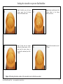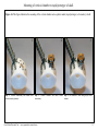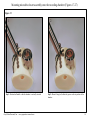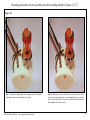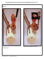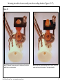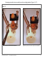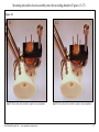
1
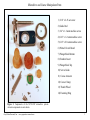
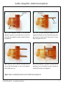
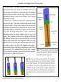
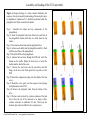
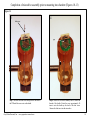
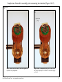
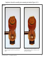
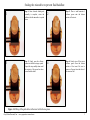
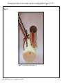
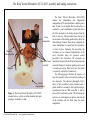
The Deep Vertical Microdrive (SC32-1DV), assembly and loading instructions.
Coarse
manipulator
Headpost
Connecting Rod
Microdrive/Insert
assembly
Headpost
Cranial
rapid prototype
Figure 1. The Deep Vertical Microdrive (SC32-1DV)
mounted onto a vertical recording chamber and rapid
prototype of a monkey’s skull.
Gray Matter Research, Inc. – www.graymatter-research.com
The Deep Vertical Microdrive (SC32-1DV)
enables the implantation and independent
manipulation of 32 microelectrodes at depths greater
than 20 mm. To accomplish this the microdrive is
coupled to a coarse manipulator system that allows
all of the electrodes to be slowly advanced into the
brain in one step. This procedure places the tips of
the electrodes at the starting position lying above the
intended target structure. Once this is completed, the
coarse manipulator is removed and the microdrive
is fixed in place. Following this procedure, the
electrodes can be advanced independently at the
user’s discretion using the precision control
provided by the microdrive. The electrodes are
intended to remain in the brain for prolonged periods
and small changes in electrode position can be used
to record new activity. When not in use, the system
is covered by a protective Titanium cap.
The following pages illustrate the sequence of
steps for assembly of the system and the loading of
the electrodes. The adjacent photograph (Fig.1)
shows a fully assembled system mounted onto a
plastic model of a monkey’s skull (rapid prototype,
reconstructed from an MRI scan) that is held in
place with a head holder system. This illustrates the
system as it would appear just prior to lowering all
of the electrodes into the brain using the coarse
manipulator.
1
Microdrive and Coarse Manipulator Parts
1) 1/16" x 2-56 set screw
2) Guide Rod
3) 1/4" x 1.2 unm machine screw
4) 0.16" x 1.2 unm machine screw
5) 0.12" x 0.8 unm machine screw
6) Printed Circuit Board
7) Plungerblock Bottom
8) Chamber Insert
9) Plungerblock Top
10) Screw Guide
11) Coarse Actuator
12) Coarse Clamp
13) Thumb Wheel
14) Fastening Ring
Figure 2. Components of the SC32-1DV microdrive system.
Actuator components are not shown.
Gray Matter Research, Inc. – www.graymatter-research.com
2
Assembly of plungerblock , chamber insert and guide rods
1
plungerblock
2
2-56 set screw
guide rod
insert
Step 1: Mount plungerblock assembly (i.e. top and bottom
plungerblock components) into the chamber insert. Be sure that the
actuator holes in the plungerblock assembly are aligned with those in
the chamber insert.
3
Step 3: Repeat step 2 until all 4 guide rods are mounted and the set
screws are tight. Mount remaining 4 set screws into the plungerblock
but do not tighten these screws.
Step 2: Mount each guide rod through the alignment holes in the
plungerblock and chamber insert. Be sure that the bottom surface of the
guide rod does not extend beyond the bottom surface of the insert
flange. Gently tighten 2-56 set screw.
4
Step 4: Retract plungerblock to top position of the guide rods then
gently tighten set screws. Be sure that the top surface of the guide rods
are flush with the top surface of the plungerblock.
Figure 3. Steps for assembling the microdrive onto the chamber insert and guide rods.
Gray Matter Research, Inc. – www.graymatter-research.com
3
Assembly and loading of the SC32 microdrive
The SC32-1 utilizes a screw-driven mechanism to bi-directionally control
electrode position along a single axis (Fig.4). Each actuator consists of a lead
screw, an eccentric brass shuttle and a compression spring. The uninsulated
end of each electrode is bonded to a shuttle using a conductive epoxy and the
electrode/shuttle assembly is loaded into the microdrive using a multistep
sequence (Fig.6, next page).
When the device is assembled, electrode position is controlled by rotation
of the lead screw (Fig.5), which causes the shuttle, and the electrode to which
it is bonded, to translate. Counter clockwise rotation of the lead screw causes
the electrode to advance and clockwise rotation causes the electrode to retract.
The movement resolution is 8 turns/mm or 125 μm for each full 360º rotation
of the screw. The design drawing shown in figure 4 illustrates the
arrangements between the actuator components and the body of the
microdrive. When assembled, the lead screw passes through the PCB and the
lower, unthreaded portion of the screw fits into a blind hole in the bottom
component of the actuator block. This configuration stabilizes the vertical
alignment of the screw. The flange on the lead screw makes contact with the
top, conductive surface on the PCB and the compression spring applies a
constant downward pressure on the flange to insure that stable contact between
the screw and the PCB is maintained when the screw guide is mounted.
Electrical connection is mediated by contact from the electrode to the shuttle,
to the lead screw, to the PCB, to the PCB connector.
Figure 4. Cross-sectional view of the design
drawing of the microdrive actuator illustrating the
relationships among the components.
Figure 5. Correct use of the precision screwdriver. The screwdriver
used to the control the actuator is very delicate and must be used with
care and proper alignment. A,B. These design drawings depict the
correct alignment between the screwdriver blade and the lead screw.
C. When the two parts are misaligned the screwdriver blade will rest
on the top surface of the lead screw. In this position, a small gap will
be apparent between the screwdriver and the top surface of the screw
guide.
Gray Matter Research, Inc. – www.graymatter-research.com
4
Assembly and loading of the SC32 microdrive
Figure 6. Design drawings of a mock actuator illustrating the
sequence of steps for assembly and loading of the microdrive prior
to implantation. Operations 2-11 should be performed while the
plungerblock is firmly mounted in the holder.
Step 1: Assemble the bottom and top components of the
plungerblock.
Step 2: Insert the polyimide tubes from below into each hole of
the plungerblock bottom until they are visible from the top
surface.
Step 3: Front load each electrode into the polyimide tubes.
Step 4: Advance each shuttle into the plungerblock until it is flush
with the top surface of the plungerblock.
Step 5: Mount the PCB on the plungerblock.
Step 6: Advance the lead screw through the PCB and ‘catch’ the
threads on the shuttle. Rotate the lead screw to retract the
shuttle onto the shaft of the screw.
Step 7: Advance the lead screw into the microdrive until the
flange on the screw sits flush against the top surface of the
PCB.
Step 8: Mount the compression spring onto the shank of the lead
screw.
Step 9: Mount the screw guide over the exposed screws/springs
and tighten down to the PCB.
Step 10: Remove the polyimide tubes from the bottom of the
drive.
Step 11: Retract each electrode by clockwise rotation of the lead
screw. Once the tip of the electrode is no longer visible,
continue retraction an additional 0.5 mm. This keeps the
electrode tips retracted within the drive and protected.
Gray Matter Research, Inc. – www.graymatter-research.com
5
Loading microelectrodes into the plungerblock/insert assembly (Figures 7-9)
1
holder
plungerblock
2-56 set screw
insert
Step1: Mount plungerblock/insert assembly into
holder, tighten holder, then rotate to a horizontal
orientation.
guide rod
Step 2: Backload PI tubing through each hole in
the insert.
2
PI tube
Figure 7.
Gray Matter Research, Inc. – www.graymatter-research.com
6
Loading microelectrodes into the plungerblock/insert assembly (Figures 7-9)
3
Step 3: Thread PI tubing into corresponding hole
in the plungerblock.
4
Step 4: Front load the electrode/shuttle assembly
into the PI tube.
electrode/shuttle
assembly
Figure 8.
Gray Matter Research, Inc. – www.graymatter-research.com
7
Loading microelectrodes into the plungerblock/insert assembly (Figures 7-9)
5
6
Step 5: Advance electrode/shuttle assembly
through PI tube until the top surface of the
shuttle is flush with the top surface of the
plungerblock (not shown).
Step 6: Remove PI tubing from below the
bottom of the chamber insert, leaving
electrode/shuttle assembly in place.
Figure 9.
Gray Matter Research, Inc. – www.graymatter-research.com
8
Completion of microdrive assembly prior to mounting into chamber (Figures 10-13)
Figure 10.
1
plungerblock
2
PCB
shuttle
2-56
set screw
guide rod
holder
insert
Step 1: Once all electrode/shuttle assemblies are loaded into
the microdrive, reorient the full assembly to a vertical
position.
Gray Matter Research, Inc. – www.graymatter-research.com
Step 2: Mount the PCB onto the top surface of the
plungerblock using the two 0.16" x 1.2 unm machine screws.
9
Completion of microdrive assembly prior to mounting into chamber (Figures 10-13)
Figure 11.
3
4
lead screw
gap
Step 3: Advance each lead screw through one of the holes in
the PCB until the screw rests on the shuttle.
Gray Matter Research, Inc. – www.graymatter-research.com
Step 4: Rotate the lead screw manually until it catches the
threads of the shuttle. Rotate the screw approximately 50
turns to raise the shuttle up the shaft of the lead screw.
Advance the lead screw into the microdrive.
10
Completion of microdrive assembly prior to mounting into chamber (Figures 10-13)
Figure 12.
5
6
compression
spring
Step 5: Advance lead screw until it seats flush against the
top surface of the plungerblock.
Gray Matter Research, Inc. – www.graymatter-research.com
Step 6: Mount a compression spring over the shaft of the
lead screw. Repeat steps 3-6 until all 32 screws and springs
are loaded.
11
Completion of microdrive assembly prior to mounting into chamber (Figures 10-13)
Figure 13.
7
Step 7: Mount the screw guide over the lead screws and
compression springs. Be sure that all screws and holes are
aligned.
Gray Matter Research, Inc. – www.graymatter-research.com
8
Step 8: Fasten the screw guide tight against the PCB by
incrementally tightening each screw in succession to avoid
any tilting of the screw guide.
12
Sealing the microdrive to prevent fluid backflow
1
3
Step 1: Once electrode loading and
assembly is complete, rotate the
holder so that the microdrive is upside
down.
Step 3: Gently press the silicone
grease into the holes using a spatula.
Repeat this step multiple times until
the majority of the grease has been
pressed into the holes.
2
4
Step 2: Place a small amount of
silicone grease onto the bottom
surface of the insert.
Step 4: Gently wipe off the excess
silicone grease from the bottom
surface of the insert. Be sure to
remove all grease from the sides of
the insert as well.
Figure 14. Filling of the guide holes in the insert with silicone grease.
Gray Matter Research, Inc. – www.graymatter-research.com
3
Sealing the microdrive to prevent fluid backflow
1
3
Step 5: Carefully remove all excess
silicone grease from the bottom
surface of the chamber insert.
Step 7: Gently move the sealant
around the bottom surface of the
insert until the entire surface is
covered with a uniform layer of the
sealant.
2
Step 6: Apply a small amount of the
silicone sealant to the bottom
surface of the insert.
4
Step 8: Allow the sealant to cure for
24 hours.
Figure 15. Sealing the bottom surface of the microdrive insert with silicone sealant.
Gray Matter Research, Inc. – www.graymatter-research.com
3
Mounting of vertical chamber to rapid prototype of skull.
Figure 16. This figure illustrates the mounting of the vertical chamber onto a plastic model (rapid prototype) of a monkey’s skull.
1
Step 1: Perform craniotomy and mount bone
screws around perimeter.
2
Step 2: Position chamber and insert within
craniotomy.
Gray Matter Research, Inc. – www.graymatter-research.com
3
Step 3: Fix chamber to skull using acrylic bone
cement.
13
Mounting microdrive/insert assembly onto the recording chamber (Figures 17-27)
Figure 17.
1
Step 1: Position skull model so that the chamber is vertically oriented.
Gray Matter Research, Inc. – www.graymatter-research.com
2
Step 2: Mount O-ring (red) within the groove on the top surface of the
chamber.
14
Mounting microdrive/insert assembly onto the recording chamber (Figures 15-27)
Figure 18.
3
Step 3: Mount the plungerblock/insert assembly onto the chamber,
using the pin on the top of the chamber as a guide.
Gray Matter Research, Inc. – www.graymatter-research.com
4
Step 4: Mount the cap screws into the holes on the top surface of the
insert. Use care during this step to avoid dropping the screws into the
insert. If this occurs it may be necessary to remove the assembly from
the chamber to retrieve the screw(s).
15
Mounting microdrive/insert assembly onto the recording chamber (Figures 15-27)
Figure 19.
5
Step 5: Tighten all of the cap screws onto the chamber using the
round-head hex wrench.
Gray Matter Research, Inc. – www.graymatter-research.com
6
Step 6: Mount the coarse manipulator onto the chamber.
16
Mounting microdrive/insert assembly onto the recording chamber (Figures 15-27)
Figure 20.
7
Step 7: Tighten the fastening ring onto the chamber and position the
holder (black) over the microdrive.
Gray Matter Research, Inc. – www.graymatter-research.com
8
Step 8: Advance the coarse manipulator until the holder makes flush
contact with the top of the microdrive. Then tighten the holder.
17
Mounting microdrive/insert assembly onto the recording chamber (Figures 15-27)
Figure 21.
9
Step 9: Loosen the set screws at the top of the guide rods.
Gray Matter Research, Inc. – www.graymatter-research.com
10
Step 10: Slowly advance the microdrive using the coarse manipulator.
18
Mounting microdrive/insert assembly onto the recording chamber (Figures 15-27)
Figure 22.
11
Step 11: Slowly advance the microdrive using the coarse manipulator.
Gray Matter Research, Inc. – www.graymatter-research.com
12
Step 12: Slowly advance the microdrive using the coarse manipulator.
19
Mounting microdrive/insert assembly onto the recording chamber (Figures 15-27)
Figure 23.
13
Step 13: Mount the cap screws into the plungerblock that are used to
fasten the plungerblock to the chamber.
Gray Matter Research, Inc. – www.graymatter-research.com
14
Step 14: Tighten the cap screws into the plungerblock.
20
Mounting microdrive/insert assembly onto the recording chamber (Figures 15-27)
Figure 24.
15
Step 15: Loosen the holder on the coarse manipulator and begin to
retract the coarse manipulator.
Gray Matter Research, Inc. – www.graymatter-research.com
16
Step 16: Retract the coarse manipulator.
21
Mounting microdrive/insert assembly onto the recording chamber (Figures 15-27)
Figure 25.
17
Step 17: Retract the coarse manipulator.
Gray Matter Research, Inc. – www.graymatter-research.com
18
Step 18: Remove the coarse manipulator.
22
Mounting microdrive/insert assembly onto the recording chamber (Figures 15-27)
Figure 26.
19
Step 19: Loosen the set screw holding the guide rods in place then
remove the guide rods.
Gray Matter Research, Inc. – www.graymatter-research.com
20
Step 20: Remove the set screws that are used for holding the guide
rods in place.
23
Mounting microdrive/insert assembly onto the recording chamber (Figures 15-27)
Figure 27.
21
Step 21: Cover the assembly with the protective cap.
Gray Matter Research, Inc. – www.graymatter-research.com
24