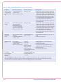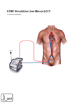
1
Impella 2.5
®
with the Automated Impella Controller
®
Circulatory Support System
INSTRUCTIONS FOR USE
& CLINICAL REFERENCE MANUAL
(United States only)
IMPORTANT NOTICE: Read this entire manual before using the Automated Impella® Controller and Impella® 2.5 Circulatory Support System (Impella®
2.5 System). The Impella® 2.5 System is to be used only in accordance with this manual. This manual is only applicable to Impella® systems using the
Automated Impella® Controller.
Information contained in this document is subject to change without notice.
©2013 Abiomed®, Inc. All rights reserved.
The ABIOMED logo and ABIOMED are registered trademarks of Abiomed, Inc. in the U.S.A. and certain foreign countries.
Recovering hearts. Saving lives. is a trademark of Abiomed, Inc.
Impella is a registered trademark of Abiomed Europe GmbH, a wholly owned subsidiary of Abiomed, Inc., in the U.S.A. and certain foreign countries.
IMPELLA® 2.5 WITH THE
AUTOMATED IMPELLA® CONTROLLER
INSTRUCTIONS FOR USE
& CLINICAL REFERENCE MANUAL
(UNITED STATES ONLY)
Rx Only
Abiomed, Inc.
22 Cherry Hill Drive
Danvers, MA 01923
978-777-5410 (voice)
978-777-8411 (fax)
[email protected] (email)
Abiomed Europe GmbH
Neuenhofer Weg 3
52074 Aachen, Germany
+49 (241) 8860-0 (voice)
+49 (241) 8860-111 (fax)
[email protected] (email)
www.abiomed.com
24-Hour Emergency Hotlines:
N. America 1-800-422-8666
Europe +49 (0) 1805 2246633
August 2013
Document No. 0042-9000 Rev. G
TABLE OF CONTENTS
INTRODUCTION
Introduction.............................................................................................. I
1 WARNINGS AND CAUTIONS
Warnings.................................................................................................. 1.1
Cautions................................................................................................... 1.3
2 I NDICATIONS, CONTRAINDICATIONS, AND POTENTIAL ADVERSE
EVENTS
Indications (United States)........................................................................ 2.1
Contraindications (United States).............................................................. 2.1
Potential Adverse Events (United States)................................................... 2.2
3 T HE IMPELLA® CATHETER AND AUTOMATED IMPELLA®
CONTROLLER
Overview.................................................................................................. 3.1
Impella® Catheter..................................................................................... 3.4
Automated Impella® Controller................................................................. 3.6
Purge Cassette.......................................................................................... 3.7
Accessories............................................................................................... 3.9
4 U
SING THE AUTOMATED IMPELLA® CONTROLLER
Overview.................................................................................................. 4.1
Automated Impella® Controller Features................................................... 4.2
Home Screen............................................................................................. 4.6
Placement Screen...................................................................................... 4.9
Purge Screen............................................................................................. 4.10
Infusion History Screen............................................................................. 4.11
Mobile Operation...................................................................................... 4.12
5 U
SING THE AUTOMATED IMPELLA® CONTROLLER
WITH THE IMPELLA® CATHETER
Pre-support Evaluation............................................................................. 5.1
Startup...................................................................................................... 5.2
Case Start................................................................................................. 5.5
Inserting the Impella® Catheter (Wired Insertion)...................................... 5.12
Wireless Insertion of the Impella® 2.5 Catheter......................................... 5.16
Positioning and Starting the Impella® Catheter......................................... 5.17
Modes of Operation.................................................................................. 5.19
Use of the Repositioning Sheath and the Peel-Away Introducer................ 5.20
Transfer to Standard Configuration........................................................... 5.21
Purge Cassette Procedures........................................................................ 5.22
Troubleshooting the Purge System............................................................ 5.26
Patient Weaning....................................................................................... 5.28
Removing the Impella® Catheter............................................................... 5.29
6 PATIENT MANAGEMENT TOPICS
Patient Management Overview................................................................. 6.1
General Patient Care Considerations ........................................................ 6.1
Transport Within the Hospital................................................................... 6.1
Transport Between Hospitals.................................................................... 6.2
Right Heart Failure.................................................................................... 6.3
ECG Interference....................................................................................... 6.4
Latex......................................................................................................... 6.4
Use of Echocardiography for Positioning of the Impella® Catheter............ 6.4
Understanding and Managing Impella®Catheter Position Alarms.............. 6.11
Suction..................................................................................................... 6.17
Hemolysis................................................................................................. 6.17
Operating the Impella® Catheter without Heparin in the Purge Solution... 6.19
Repositioning Guide.................................................................................. 6.19
Placement Signal Lumen........................................................................... 6.22
Timed Data Recording............................................................................... 6.23
Operating the Impella® Catheter in Electromagnetic Fields....................... 6.24
Transferring from the Automated Impella® Controller to a New
Automated Impella® Controller................................................................. 6.26
Transferring from the Automated Impella® Controller to an Impella®
Console.................................................................................................... 6.27
Transferring from an Impella® Console to the Automated Impella®
Controller.................................................................................................. 6.28
Emergency Shutdown Procedure............................................................... 6.28
7 A
UTOMATED IMPELLA® CONTROLLER ALARMS
Alarms Overview....................................................................................... 7.1
Alarm Message Summary.......................................................................... 7.3
8 G
ENERAL SYSTEM INFORMATION
Terminology, Abbreviations, and Symbols................................................. 8.1
Automated Impella® Controller Mechanical Specifications........................ 8.3
Automated Impella® Controller Electrical Specifications............................ 8.3
Equipment Design..................................................................................... 8.4
Equipment Classifications......................................................................... 8.4
Federal Communications Commission (FCC) Notice................................... 8.5
Electromagnetic Compatibility.................................................................. 8.5
Slave Monitor Connection......................................................................... 8.8
Alarm Delay Information........................................................................... 8.9
Patient Environment.................................................................................. 8.9
White Connector Cable............................................................................. 8.10
Impella® Catheter Parameters................................................................... 8.10
Impella® 2.5 Catheter Dimensions............................................................. 8.11
Anatomic Considerations.......................................................................... 8.12
Cleaning................................................................................................... 8.12
Storing the Automated Impella® Controller............................................... 8.13
Returning an Impella® Catheter to Abiomed (United States)...................... 8.13
APPENDICES
Appendix A: Impella® System Limited Service Warranty (United States)... A.1
Appendix B: Abiomed-Approved Guidewires and Introducers.................. B.1
Appendix C: Automated Impella® Controller Menu Structure................... C.1
Appendix D: Axillary Insertion Technique................................................. D.1
TABLE OF CONTENTS
FIGURES
Figure 3.1 Impella® Catheter in the Heart.................................................. 3.1
Figure 3.2Set-up Configuration of the Automated Impella® Controller,
Impella® Catheter, and Accessories........................................... 3.3
Figure 3.3Standard Configuration of the Automated Impella®
Controller, Impella® Catheter, and Accessories......................... 3.3
Figure 3.4 Impella® Catheter..................................................................... 3.4
Figure 3.5 Automated Impella® Controller – Front View............................ 3.6
Figure 3.6 Purge Cassette......................................................................... 3.7
Figure 3.7 White Connector Cable............................................................. 3.9
Figure 3.8 Introducer Kit............................................................................ 3.9
Figure 3.90.018 inch, 260 cm Placement Guidewire................................. 3.9
Figure 3.10 Dextrose Solution..................................................................... 3.10
Figure 3.11 Automated Impella® Controller Cart......................................... 3.10
Figure 4.1 Automated Impella® Controller Features – Front View.............. 4.2
Figure 4.2 Automated Impella® Controller Features – Side Views.............. 4.4
Figure 4.3 Home Screen............................................................................ 4.6
Figure 4.4 Placement Screen..................................................................... 4.9
Figure 4.5 Purge Screen............................................................................. 4.10
Figure 4.6 Infusion History Screen............................................................. 4.12
Figure 5.1 Automated Impella® Controller Power Switch........................... 5.3
Figure 5.2 Automated Impella® Controller Startup Screen......................... 5.4
Figure 5.3 Initial Case Start Screen............................................................ 5.5
Figure 5.4 Inserting Purge Cassette into Automated Impella® Controller... 5.6
Figure 5.5 Inserting the Catheter Plug into the Connector Cable............... 5.7
Figure 5.6 Snapping Plastic Clip to Connector Cable.................................. 5.7
Figure 5.7 Priming the Impella Purge Lumen.............................................. 5.8
Figure 5.8 Connecting the Luer(s) to the Impella® Catheter....................... 5.8
Figure 5.9 Priming the Placement Signal Lumen........................................ 5.9
Figure 5.10 Squeezing the White Flush Valve to Prime the Placement
Signal Lumen............................................................................ 5.9
Figure 5.11 Entering Purge Fluid Information............................................... 5.10
Figure 5.12 Connecting the Purge Tubing to the Connector Cable............... 5.11
Figure 5.13Set-up Configuration of the Impella® System............................ 5.11
Figure 5.14 Inserting the Peel-Away Introducer........................................... 5.12
Figure 5.15 Inserting the Diagnostic Catheter.............................................. 5.13
Figure 5.16Loading the Catheter on the Guidewire using the EasyGuide
Lumen...................................................................................... 5.13
Figure 5.17Loading the Catheter on the Guidewire without the
EasyGuide Lumen and Aligning the Placement Guidewire......... 5.14
Figure 5.18 Inserting the Impella® Catheter................................................. 5.15
Figure 5.19 Aortic Waveform on Placement Signal Screen........................... 5.15
Figure 5.20 FLOW CONTROL Menu............................................................. 5.17
Figure 5.21 FLOW CONTROL Meter............................................................. 5.18
Figure 5.22 Ventricular Waveform on Placement Signal Screen.................... 5.18
Figure 5.23 Removing the Peel-Away Introducer......................................... 5.20
Figure 5.24Standard Configuration for Impella® System after Transfer
from the Set-up Configuration.................................................. 5.22
Figure 5.25 Disconnecting the Y Connector from the Purge Cassette
Tubing...................................................................................... 5.23
Figure 6.1
Labeled TEE and TTE Images of the Impella® Catheter
Position.................................................................................... 6.5
Figure 6.2 Transesophageal Echocardiographic (TEE) Illustrations of
Impella® Catheter Position........................................................ 6.8
Figure 6.3 Transthoracic Echocardiographic (TTE) Illustrations of
Impella® Catheter Position........................................................ 6.9
Figure 6.4 Correct and Incorrect Impella® Catheter Position
(Color Doppler TTE).................................................................. 6.10
Figure 6.5 Correct Impella® Catheter Position........................................... 6.12
Figure 6.6 Impella® Catheter Fully in Ventricle........................................... 6.13
Figure 6.7Impella® Catheter Completely in the Aorta or Inlet and
Outlet Areas
in Ventricle and Open Pressure Area in Aorta............................ 6.14
Figure 6.8 Impella® Catheter Position Unknown........................................ 6.15
Figure 6.9 Impella® Catheter Outlet Area on or near Aortic Valve.............. 6.16
Figure 6.10 First Repositioning Guide Screen............................................... 6.20
Figure 6.11 Second Repositioning Guide Screen.......................................... 6.20
Figure 6.12 Third Repositioning Guide Screen............................................. 6.21
Figure 6.13 Exit Repositioning Guide Screen................................................ 6.21
Figure 6.14 Displacing Air During Flush Solution Change Out Procedure..... 6.23
Figure 8.1 Automated Impella® Controller Patient Environment................. 8.9
Figure 8.2 Impella® 2.5 Catheter Dimensions............................................ 8.11
TABLES
Table 3.1
Table 3.2
Table 3.3
Table 3.4
Table 4.1
Table 4.2
Table 4.3
Table 5.1
Table 5.2
Table 6.1
Table 6.2
Table 6.3
Table 6.4
Table 7.1
Table 7.2
Table B.1
Table B.2
Impella® Set-up and Insertion Kit Components......................... 3.2
Impella® Catheter Components................................................ 3.4
Purge Cassette Components..................................................... 3.8
Impella® Catheter and Automated Impella® Controller
Accessories............................................................................... 3.9
Automated Impella® Controller Front View Features................. 4.3
Automated Impella® Controller Side View Features................... 4.5
Automated Impella® Controller Display Elements...................... 4.6
Evaluation Prior to Inserting the Impella® Catheter................... 5.1
Performance Level Flow Rates................................................... 5.19
Guide for Managing Hemolysis in Various Circumstances.......... 6.18
Recommended Standards for Maintenance of the
Placement Signal...................................................................... 6.22
Troubleshooting When Operating the Impella® Catheter
in the Presence of an EAM System............................................ 6.24
Troubleshooting When Operating the Impella Catheter
in the Presence of a MNS System.............................................. 6.25
Alarm Levels............................................................................. 7.1
Automated Impella® Controller Alarm Messages...................... 7.3
Alternative Guidewires............................................................. B.1
Alternative Introducer Sheaths.................................................. B.1
INTRODUCTION
INTRODUCTION
PURPOSE OF MANUAL
This Instructions for Use & Clinical Reference Manual is designed for healthcare professionals.
It contains clinical and technical information to guide healthcare professionals in their use of the
Impella® 2.5 Catheter with the Automated Impella® Controller. The Impella® System performs
life-sustaining functions. To use the system you must understand and follow these instructions.
The Impella® System may be used only for its intended purpose.
MANUAL OVERVIEW
This manual provides instructions for use of the Impella® 2.5 Catheter with the Automated
Impella® Controller. The following summarizes the contents of each section of the manual.
• Section 1: Warnings and Cautions discusses the warnings and cautions pertaining
to the use of the Impella® Catheter with the Automated Impella® Controller.
• Section 2: Indications, Contraindications, and Potential Adverse Events
discusses indications for use of the Impella® Catheter with the Automated Impella®
Controller, contraindications, and potential adverse events that may be associated with
the use of the system.
• Section 3: The Impella® Catheter and Automated Impella® Controller provides
an overview of the system and describes its major components and features.
• Section 4: Using the Automated Impella® Controller describes the controls and
various screen types on the Automated Impella® Controller.
• Section 5: Using the Automated Impella® Controller with the Impella®
Catheter provides the procedures for using the Impella® System.
• Section 6: Patient Management Topics provides key information on various topics
related to management of patients with the Impella® Catheter and Automated Impella®
Controller.
• Section 7: Automated Impella® Controller Alarms provides a listing of Automated
Impella® Controller alarms as well as information on what to do to resolve them.
• Section 8: General System Information contains information including definitions
for key terms that appear in the manual, descriptions of the abbreviations and symbols
that appear on Impella® Catheter and Automated Impella® Controller components and
packaging, technical information pertaining to the Impella® Catheter and Automated
Impella® Controller, and instructions on cleaning and storing system components as well
as returning components to Abiomed.
• Appendices at the end of the manual provide supplemental information about topics
including the Impella® Limited Service Warranty; Abiomed-approved guidewires and
introducers; the Automated Impella® Controller menu structure; and axillary insertion
technique.
Impella® 2.5 Catheter with the Automated Impella® Controller
I
1 WARNINGS AND CAUTIONS
WARNINGS.................................................................................................... 1.1
CAUTIONS.....................................................................................................1.3
WARNINGS
1
Fluoroscopy is required to guide placement of the Impella® Catheter. The small
placement guidewire must be reliably observed at all times.
Be sure that the stopcock on the peel-away introducer or repositioning sheath is
always kept in the closed position. Significant bleed back can result if the stopcock
is open.
Warnings
Warnings alert you to
situations that can cause
death or serious injury. The
red symbol
appears before
warning messages.
Avoid manual compression of the inlet and outlet areas of the cannula assembly.
The sterile components of the Impella® System can be used only if the sterilization
indicators show that the contents have been sterilized, the packaging is not
damaged, and the expiration date has not elapsed.
Do NOT resterilize or reuse the Impella® Catheter. It is a disposable device and is
intended for single use only. Reuse, reprocessing, or resterilization may compromise
the structural integrity of the catheter and/or lead to catheter failure which, in turn,
may result in patient injury, illness, or death.
Retrograde flow will occur across the aortic valve if the Impella® Catheter is set at a
flow rate of less than 0.5 L/min.
To prevent malfunction of the locking mechanism of the peel-away introducer,
do NOT hold the hemostatic valve while inserting into the artery.
To prevent failure of the peel-away introducer, remove the peel-away introducer
prior to transport when activated clotting time (ACT) is less than 150 seconds.
Do NOT use saline in the purge system.
Do NOT use an Impella® System if any part of the system is damaged.
To prevent the risk of explosion, do NOT operate the Impella® System near
flammable anesthetics.
If at any time during the course of support with the Impella® Catheter, the
Automated Impella® Controller alarms “Purge Pressure Low” or “Purge System
Open,” follow the instructions presented in section 5 of this manual.
Do NOT subject a patient who has been implanted with an Impella® Catheter to
magnetic resonance imaging (MRI). The strong magnetic energy produced by an MRI
machine may cause the Impella® System components to stop working, and result in
injuries to the patient. An MRI may also damage the electronics of the Impella® System.
Cardiopulmonary support (CPR) should be initiated immediately per hospital
protocol if indicated for any patient supported by the Impella® Catheter. When
initiating CPR, reduce the Impella® Catheter flow rate. When cardiac function has
been restored, return flow rate to the previous level and assess placement signals
on the controller.
Impella® 2.5 Catheter with the Automated Impella® Controller
1.1
WARNINGS AND CAUTIONS
Use of the Impella® System by trained and experienced practitioners has been
associated with improved outcomes. Consequently, the first use of Impella® should
be preceded by the completion of a contemporary Abiomed Impella® training
program and include on-site proctoring during the first use by Abiomed clinical
support personnel certified in the use of Impella®.
During defibrillation, do NOT touch the Impella® Catheter, cables, or Automated
Impella® Controller.
Power the Automated Impella® Controller using its internal battery if the integrity of
the protective earth conductor is questionable.
Lithium-ion battery replacement by inadequately trained personnel could result in
excessive temperatures, fire, or explosion. Only technicians authorized by Abiomed
should remove or change the battery.
To avoid risk of electric shock, this equipment must only be connected to a supply
mains with protective earth.
No modification of this equipment is allowed.
Medical electrical equipment needs special precautions regarding EMC and needs
to be installed and put into service according to the electromagnetic compatibility
(EMC) information provided in section 8 of this manual.
During transport, the Automated Impella® Controller may be exposed to stronger
electromagnetic disturbance than during in-hospital use. Strong electromagnetic
disturbance may cause the Automated Impella® Controller to display soft button
menu selections that were not selected by the user. Operators should be aware
that, under these conditions, the operating parameters are not affected. No user
intervention is required. Monitor Impella® Catheter flow and patient hemodynamics
to confirm normal operation. The condition will resolve itself once the Automated
Impella® Controller is no longer exposed to the disturbance.
Portable and mobile RF communications equipment can affect medical electrical
equipment.
The equipment or system should not be used adjacent to or stacked with other
equipment. If adjacent or stacked use is necessary, the equipment or system should
be observed to verify normal operation in the configuration in which it will be used.
Use of cables, other than those sold by Abiomed, may result in increased emissions
or decreased immunity of the Automated Impella® Controller.
The Automated Impella® Controller uses RFID (radio frequency identification) to
identify and communicate with the purge cassette. Other equipment may interfere with
the Automated Impella® Controller even if that other equipment complies with CISPR
emission requirements.
Infusion through the sideport of the introducer can be done only after all air is
removed from the introducer. If performed, the infusion should be done for flushing
purposes only and NOT for delivering therapy or monitoring blood pressure.
1.2
Instructions for Use & Clinical Reference Manual (US)
CAUTIONS
1
Patients with aortic stenosis or other abnormal aortic valve performance may be
compromised by the use of the Impella® Catheter. Patients with aortic valve disease
should be observed for aortic insufficiency.
Partial circulatory support with Impella® has been associated with more extensive
use of rotational atherectomy. Extensive use of rotational atherectomy has been
associated with a periprocedural increase in cardiac biomarkers indicative of
myocardial injury. Rotational atherectomy, with or without the use of hemodynamic
support, should be used in accordance with the manufacturer’s instructions for use.
Cautions
Cautions indicate situations
in which equipment may
malfunction, be damaged, or
cease to operate. The yellow
symbol
appears before
caution messages.
Physicians should exercise special care when inserting the Impella® Catheter
in patients with known or suspected unrepaired abdominal aortic aneurysm or
significant descending thoracic aortic aneurysm or dissection of the ascending,
transverse, or descending aorta.
Use only original accessories and replacement parts supplied by Abiomed.
Do NOT use damaged or contaminated connector cables.
To prevent device failure, do NOT start the Impella® Catheter until the guidewire
has been removed.
Do NOT remove the Impella® Catheter over the length of the guidewire.
When replacing the purge cassette, the replacement process must be completed
within 2 minutes. The Impella® Catheter may be damaged if replacement takes
longer than 2 minutes.
To prevent malfunction of the Automated Impella® Controller, avoid long-term
exposure to direct sunlight and excessive heat (40°C).
To prevent overheating and improper operation, do NOT block the cooling vents of
the Automated Impella® Controller while it is operating.
Do NOT kink or clamp the Impella® Catheter or the peel-away introducer.
During case start, make sure the yellow luer connection between the purge tubing
and Y connector is tightened and not leaking.
The Li-Ion batteries must be charged for 5 hours prior to system operation in order
to meet the runtime requirement of 1 hour. Failure to do so will yield a shorter
runtime. After being unplugged, the Automated Impella® Controller will operate for
at least 60 minutes after the batteries have been fully charged.
Minimize exposure of Impella® System components to sources of electromagnetic
interference (EMI). Exposure to sources of EMI, such as cell phones and two-way
radios, may cause operational interference. To clear interference, either increase the
distance between system components and the EMI source or turn off the EMI source.
Impella® 2.5 Catheter with the Automated Impella® Controller
1.3
WARNINGS AND CAUTIONS
Handle with care. The Impella® Catheter can be damaged during removal from
packaging, preparation, insertion, and removal. Do NOT bend, pull, or place excess
pressure on the catheter or mechanical components at any time.
Operation of Impella® System components may interfere with the operation of other
devices. If interference occurs, increase the distance between the device and system
components.
Have a backup Automated Impella® Controller, purge cassette, connector cable,
and Impella® Catheter available in the unlikely event of a device failure.
Do NOT use the bed mount as a handle.
Do NOT alter the Impella® Introducer kit in any way.
Aspiration and saline flushing of the Impella® Introducer kit sheath, dilator, and
valve should be performed to help minimize the potential for air embolism and clot
formation.
Indwelling introducer sheaths should be internally supported by a catheter or
dilator.
Dilators and catheters should be removed slowly from the sheath. Rapid removal
may damage the valve, resulting in blood flow through the valve.
Never advance the guidewire or sheath when resistance is met. Determine the
cause of resistance using fluoroscopy and take remedial action.
When injecting or aspirating through the sheath, use the sideport only.
1.4
Instructions for Use & Clinical Reference Manual (US)
2 INDICATIONS, CONTRAINDICATIONS,
AND POTENTIAL ADVERSE EVENTS
INDICATIONS (UNITED STATES)....................................................................2.1
CONTRAINDICATIONS (UNITED STATES)......................................................2.1
POTENTIAL ADVERSE EVENTS (UNITED STATES)......................................... 2.2
2
INDICATIONS (UNITED STATES)
INDICATIONS, CONTRAINDICATIONS, AND POTENTIAL ADVERSE EVENTS
The Impella® 2.5 Circulatory Support System is intended for partial circulatory support using an
extracorporeal bypass control unit, for periods up to 6 hours. It is also intended to be used to
provide partial circulatory support (for periods up to 6 hours) during procedures not requiring
cardiopulmonary bypass.
The Impella® 2.5 Circulatory Support System also provides pressure measurements which are
useful in determining intravascular pressure.
The Automated Impella® Controller is intended to be used by trained healthcare professionals
in healthcare facilities and medical transport (ie, ambulance, helicopter, or fixed-wing aircraft)
environments.
CONTRAINDICATIONS (UNITED STATES)
Patients with aortic stenosis or other abnormal aortic valve performance may be
compromised by the use of the Impella® Catheter. Patients with aortic valve disease
should be observed for aortic insufficiency.
• Mechanical aortic valve or heart constrictive device
• Aortic valve stenosis/calcification (graded as ≥ +2 equivalent to an orifice area of
1.5 cm2 or less)
• Moderate to severe aortic insufficiency (echocardiographic assessment of aortic
insufficiency graded as ≥ +2)
• Severe peripheral arterial obstructive disease that would preclude Impella® device
placement
Impella® 2.5 Catheter with the Automated Impella® Controller
2.1
POTENTIAL ADVERSE EVENTS (UNITED STATES)
2.2
• Aortic insufficiency
• Insertion site infection
• Aortic valve injury
• Myocardial infarction
• Arrhythmia
• Perforation
• Atrial fibrillation
• Renal failure
• Bleeding
• Respiratory dysfunction
• Cardiogenic shock
• Sepsis
• Cardiac tamponade
• Thrombocytopenia
• Cerebral vascular accident (CVA) /
Stroke
• Thrombotic vascular (non-CNS)
complication
• Death
• Transient ischemic attack (TIA)
• Device malfunction
• Vascular injury
• Hemolysis
• Ventricular fibrillation
• Hepatic failure
• Ventricular tachycardia
Instructions for Use & Clinical Reference Manual (US)
3 T HE IMPELLA® CATHETER AND
AUTOMATED IMPELLA® CONTROLLER
OVERVIEW.....................................................................................................3.1
Reusable System Components..........................................................................3.2
Single-use System Components........................................................................3.2
Impella® Set-up and Insertion Kit......................................................................3.2
System Configurations......................................................................................3.3
IMPELLA® CATHETER.....................................................................................3.4
AUTOMATED IMPELLA® CONTROLLER..........................................................3.6
PURGE CASSETTE..........................................................................................3.7
ACCESSORIES................................................................................................3.9
OVERVIEW
3
THE IMPELLA® CATHETER AND AUTOMATED IMPELLA® CONTROLLER
The Impella® Catheter is an intravascular microaxial blood pump that supports a patient’s
circulatory system. The Impella® Catheter is inserted percutaneously through the femoral artery
and into the left ventricle (see Figure 3.1).
Figure 3.1 Impella® Catheter in the Heart
When properly positioned, the Impella® Catheter delivers blood from the inlet area, which sits
inside the left ventricle, through the cannula, to the outlet opening in the ascending aorta.
Physicians and device operators monitor the correct positioning and functioning of the Impella®
Catheter on the display screen of the Automated Impella® Controller.
This section describes the components of the Impella® Catheter and the Automated Impella®
Controller, as well as the accessory components.
Impella® 2.5 Catheter with the Automated Impella® Controller
3.1
REUSABLE SYSTEM COMPONENTS
The Impella® System consists of the following reusable components:
• Automated Impella® Controller—provides the user interface, alarm indications, and
portable battery
• Automated Impella® Controller cart—for easy transport of the Automated Impella®
Controller
SINGLE-USE SYSTEM COMPONENTS
The Impella® System also includes the following single-use components:
• Impella® Catheter
• Purge cassette
• Introducer kit
• 0.018 inch, 260 cm placement guidewire
• Connector cable
IMPELLA® SET-UP AND INSERTION KIT
The components of the Impella® System are packaged into a single box called the
Impella® Set-up and Insertion kit. Table 3.1 describes the contents of this kit.
Table 3.1 Impella® Set-up and Insertion Kit Components
The Impella® Set-up and Insertion kit contains the following:
• Impella® Catheter
• 0.018 inch, 260 cm placement guidewire
• Connector cable
• Purge cassette
• Introducer kit
»»
»»
»»
»»
»»
3.2
Peel-away introducer (13 Fr for Impella® 2.5)
Dilator (13 Fr for Impella® 2.5)
18 G Seldinger needle
10 cc syringe
0.035 inch stiff access guidewire
Instructions for Use & Clinical Reference Manual (US)
SYSTEM CONFIGURATIONS
3
D20 D20
THE IMPELLA® CATHETER AND AUTOMATED IMPELLA® CONTROLLER
Figure 3.2 illustrates how the Automated Impella® Controller connects to the Impella® Catheter
and accessory components in the initial set-up configuration.
Dextrose
Solution
Automated Impella® Controller
Impella® Catheter
Purge Cassette
Connector Cable
Y-Connector
Figure 3.2 S
et-up Configuration of the Automated Impella® Controller, Impella®
Catheter, and Accessories
Figure 3.3 illustrates the standard configuration of the Impella® Catheter, Automated Impella®
Controller, and accessory components.
D20
Dextrose
Solution
Sodium Chloride (NaCl)
Solution in Pressure Bag
Automated Impella® Controller
Impella® Catheter
Purge Cassette
Connector Cable
Y-Connector
Figure 3.3 S
tandard Configuration of the Automated Impella® Controller, Impella®
Catheter, and Accessories
Impella® 2.5 Catheter with the Automated Impella® Controller
3.3
IMPELLA® CATHETER
The Impella® Catheter is an intravascular microaxial blood pump that delivers up to
2.5 liters of blood per minute from the left ventricle into the aorta. Figure 3.4 illustrates the
Impella® Catheter. Table 3.2 describes each component from the pigtail at one end to the check
valve on the other end.
Pigtail
Inlet Area
Radiopaque
Marker
EasyGuide
Lumen
Outlet
Area
Cannula
Catheter
Shaft
Motor
Housing
Open Pressure Area
Check Valve
Red Pressure
Sidearm
Pressure
Reservoir
Clear Sidearm
Repositioning Unit
Infusion Filter
Red Impella® Plug
Figure 3.4 Impella® Catheter
Table 3.2 Impella® Catheter Components
3.4
Component
Description
Pigtail
The 6 Fr pigtail is attached to the cannula at the distal end of the inlet
area. It assists with stabilizing the catheter in the correct position in
the left ventricle.
Inlet area
The inlet area, located at the distal tip of the cannula, has four
openings (windows) that allow blood to be drawn into the inlet and
channeled through the cannula.
Radiopaque marker
The radiopaque marker on the catheter shaft is visible with fluoroscopy
and, when properly positioned, appears at the level of the aortic valve
annulus
Cannula
The cannula (12 Fr for the Impella® 2.5) has a spiral-shaped reinforced
body that is shaped in a 45-degree angle. The cannula is made of
nitinol and covered in polyurethane.
Outlet area
The proximal end of the cannula is attached to the outlet area where
the blood exits the cannula.
EasyGuide lumen
The red loading lumen, which runs from the tip of the pigtail through
the outlet area of the cannula, facilitates loading the catheter onto the
guidewire
Instructions for Use & Clinical Reference Manual (US)
Table 3.2 Impella® Catheter Components (continued)
Motor housing
The motor housing (12 Fr for the Impella® 2.5) consists of an
encapsulated motor.
Open pressure area
The open pressure area is an opening located between the motor
housing and the distal end of the catheter shaft.
Catheter shaft
A 9 Fr catheter shaft is located between the motor housing and the red
Impella® plug. The lumen of the catheter shaft contains a purge lumen,
a pressure measurement lumen, and an electrical cable.
The catheter shaft has longitudinal and transversal marks:
• The longitudinal mark along the inner radius shows correct position
of the 0.018 inch, 260 cm placement guidewire once backloaded on
the Impella® Catheter.
• The transversal marks at 1 cm intervals with numbers every 5 cm
aid in proper positioning.
Repositioning unit
The repositioning unit consists of a sheath, an anticontamination
sleeve with an anchoring ring, and suture pads.
• The sheath (with hemostatic valve) is graduated from 9 Fr to
13 Fr. It is located on the catheter shaft and allows repositioning of
the catheter.
• The anchoring ring of the anticontamination sleeve secures the
sheath to the catheter.
• The StatLock® compatible suture pads help secure the repositioning
sheath to the patient’s skin.
Red Impella® plug
The red Impella® plug at the proximal end of the catheter connects the
catheter to the Automated Impella® Controller through a connector
cable. It contains:
• A pressure transducer that translates pressure for the pressure
lumen proximal to the motor
• Memory that retains operating parameters in case the patient needs
to be transferred to another controller
• The placement signal lumen that allows for pressure and waveform
displays
It has two sidearms: a red pressure sidearm and a clear sidearm.
Red pressure sidearm
The red pressure sidearm is attached to a standard pressure bag and is
used to prime the line of the pressure measurement system.
Clear sidearm
The clear sidearm is attached to the purge cassette tubing. It leads to
the infusion filter, the pressure reservoir, and the check valve.
Infusion filter
The infusion filter prevents bacterial contamination and air from
entering the purge lumen.
Pressure reservoir
The pressure reservoir includes a flexible rubber diaphragm that
provides additional filling volume by means of an expansion chamber
during purge solution change.
Check valve
The yellow check valve ensures that purge fluid does not flow in the
reverse direction when the purge solution is exchanged.
Impella® 2.5 Catheter with the Automated Impella® Controller
Repositioning Sheath:
Inner vs Outer Diameter
The repositioning sheath has
a graduated inner diameter
of 9 Fr to 13 Fr. The outer
diameter is graduated
from 11 Fr to 15 Fr for the
Impella® 2.5.
3.5
THE IMPELLA® CATHETER AND AUTOMATED IMPELLA® CONTROLLER
Description
3
Component
AUTOMATED IMPELLA® CONTROLLER
Automated Impella®
Controller Battery Power
The controller can operate
on its internal lithium-ion
(Li-Ion) battery for at least 60
minutes when fully charged.
The Automated Impella® Controller (see Figure 3.5) provides three vital functions to the
operation of the Impella® Catheter:
• The controller provides an interface for monitoring and controlling the function of the
Impella® Catheter
• The controller provides a fluid purge to the Impella® Catheter
• The controller provides backup power when the Impella® System is operated away from
AC power
The controller weighs 26 lbs (11.8 kg) and can operate on its internal battery for at least 60
minutes when fully charged.
Automated Impella® Controller operation is described in detail in section 4 of this manual.
Figure 3.5 Automated Impella® Controller – Front View
3.6
Instructions for Use & Clinical Reference Manual (US)
PURGE CASSETTE
3
THE IMPELLA® CATHETER AND AUTOMATED IMPELLA® CONTROLLER
Do not use saline in the purge system.
The purge cassette delivers rinsing fluid to the Impella® Catheter. The purge fluid (typically 20%
dextrose solution) flows from the purge cassette through the catheter to the microaxial blood
pump to prevent blood from entering the motor. When the purge cassette is properly installed
in the Automated Impella® Controller, the words on it are upright and facing you. The image of
the purge fluid appears on the left with arrows pointing toward the image of the person on the
right. Figure 3.6 illustrates the purge cassette and related components. Table 3.3 describes each
component.
Purge Fluid Spike
Purge Cassette
Purge Pressure
Transmitter
Y Connector
Purge Tubing
Supply Line
Yellow Luer
Connector
Figure 3.6 Purge Cassette
Impella® 2.5 Catheter with the Automated Impella® Controller
3.7
Table 3.3 Purge Cassette Components
Y connector for Set-up
Configuration
The Y connector attached to
the purge tubing is used for
the initial set-up configuration
of the Impella® 2.5 System.
Switch to the standard
configuration as soon as
practical.
3.8
Component
Description
Purge fluid spike
One end spikes the purge fluid bag and the other end connects the
bag to the purge cassette supply line
Supply line
Carries fluid from the purge fluid bag to the purge cassette
Purge cassette
Contains the components for delivering the purge fluid; maintains the
pressure barrier between the blood and the motor to prevent blood
from entering the motor
Purge pressure
transmitter
Transmits pressure to the controller based on the purge pressure in
the purge tubing; a sensor in the controller measures the pressure so
that it can be displayed on the screen and used by the purge pressure
algorithm to maintain the purge pressure
Purge tubing
Carries purge fluid from the purge cassette to the Impella® Catheter
Yellow luer connector
Connects the purge tubing to the Y connector at case start and to the
check valve (yellow luer lock) on the Impella® Catheter during system
change
Y connector
Adapter that connects the purge tubing to the sidearms of the Impella®
Catheter during case start. The Y connector consist of:
• Yellow luer that connects to the clear sidearm
• Red luer that connects to the red sidearm
• Cap for the red luer when it is disconnected from the sidearm for
transfer to the standard configuration
• Clamp for the purge tubing leading to the red sidearm
• Rectangular antibacterial air filter
Instructions for Use & Clinical Reference Manual (US)
ACCESSORIES
3
THE IMPELLA® CATHETER AND AUTOMATED IMPELLA® CONTROLLER
Table 3.4 illustrates and describes the accessories used with the Impella® Catheter and
Automated Impella® Controller.
Table 3.4 Impella® Catheter and Automated Impella® Controller Accessories
Component
Description
The white connector cable connects the Impella®
Catheter to the Automated Impella® Controller.
Clips on the cable are used to secure the purge
tubing to the cable.
• T he socket at the black end of the cable
connects to the Impella® Catheter plug.
• The white plug at the opposite end of the cable
is inserted into the blue catheter plug on the
front of the Automated Impella® Controller.
Figure 3.7 White Connector Cable
The introducer kit is used to position the Impella®
Catheter. It contains:
• P eel-away introducer—with hemostatic valve for
tight fit around components and
single-step “break-away” configuration
•D
ilator—easy to insert and remove with soft
design for atraumatic approach into femoral artery
• 1 8 G Seldinger needle
• 1 0 cc syringe
• 0 .035 inch stiff access guidewire
Figure 3.8 Introducer Kit
The 0.018 inch, 260 cm placement guidewire
is used for the placement of the catheter. The
guidewire has a radiopaque, shapable tip.
Guidewire Use
It is important to use only
the guidewire supplied with
the system or an Abiomedapproved alternative.
Refer to Appendix B for more
information about Abiomedapproved guidewires.
Figure 3.9 0
.018 inch, 260 cm
Placement Guidewire
Impella® 2.5 Catheter with the Automated Impella® Controller
3.9
Component
Description
Hospital Provided:
Dextrose solution (typically 20% dextrose in water
with 50 IU/mL of heparin) is used as the purge
fluid through the Impella® Catheter.
Figure 3.10 Dextrose Solution
The Automated Impella® Controller cart holds
the Automated Impella® Controller. The cart has
wheels for easy transport of the controller and a
storage basket. (For more information, including
assembly instructions, refer to the Automated
Impella® Controller cart instructions for use.)
Figure 3.11 Automated Impella®
Controller Cart
3.10
Instructions for Use & Clinical Reference Manual (US)
4 U
SING THE AUTOMATED IMPELLA®
CONTROLLER
OVERVIEW.....................................................................................................4.1
AUTOMATED IMPELLA® CONTROLLER FEATURES........................................ 4.2
HOME SCREEN...............................................................................................4.6
PLACEMENT SCREEN.....................................................................................4.9
Placement Signal Waveform.............................................................................4.9
Motor Current Waveform................................................................................ 4.10
PURGE SCREEN............................................................................................4.10
Purge Flow..................................................................................................... 4.11
Purge Pressure................................................................................................ 4.11
INFUSION HISTORY SCREEN........................................................................ 4.11
MOBILE OPERATION.................................................................................... 4.12
OVERVIEW
4
USING THE AUTOMATED IMPELLA® CONTROLLER
The Automated Impella® Controller is the primary user control interface for the Impella®
Catheter. It controls the Impella® Catheter performance, monitors the catheter for alarms, and
provides real-time catheter position information regarding the location of the catheter across
the aortic valve. The controller can be powered by AC power or can operate on internal battery
power for at least 60 minutes when fully charged.
This section of the manual discusses Automated Impella® Controller features and displays.
Impella® 2.5 Catheter with the Automated Impella® Controller
4.1
AUTOMATED IMPELLA® CONTROLLER FEATURES
IMPORTANT NOTE: The underside of the Automated Impella® Controller has a battery switch to turn on the batteries.
This switch is turned off for shipping purposes. Before operating the Automated Impella® Controller for the first time,
make sure you turn this switch on. If the battery switch is not turned on, the Automated Impella® Controller will not be
able to operate on battery power.
Figure 4.1 illustrates the features on the front of the Automated Impella® Controller. These features are described in
Table 4.1.
Display Screen
SOFT BUTTONS
MUTE ALARM
FLOW CONTROL
Power Indicator
DISPLAY
Selector Knob
PURGE SYSTEM
MENU
Purge Pressure
Transmitter
Catheter Plug
Purge Cassette
Purge Cassette Door
(open)
Figure 4.1 Automated Impella® Controller Features – Front View
4.2
Instructions for Use & Clinical Reference Manual (US)
Table 4.1 Automated Impella® Controller Front View Features
4
Description
Display screen
Displays user information, including the labels for the soft buttons.
(Display screen elements described in detail later in this section.)
Display Options
Soft buttons
Display, open, and close menus. The function for each soft button is defined by
labels adjacent to the button on the display screen; function changes depending
on the screen. (Soft button functions are described in Table 4.3.)
When the Impella® Catheter is running, the default soft button labels are as
follows:
•M
UTE ALARM
• F LOW CONTROL
•D
ISPLAY
•P
URGE SYSTEM
•M
ENU
If equipped with a VGA
connector, the controller can
be connected to a monitor
to display information on
another screen as described
under “Slave Monitor
Connection” in section 8 of
this manual.
Power indicator
LED light above the selector knob; indicates the power status of the
Automated Impella® Controller.
• Green light—controller is on and plugged into AC power or running on
battery power
• Amber light—controller is off but plugged into AC power
• No light—controller is off and not plugged into AC power
Selector knob
Rotating push button; turn clockwise and counterclockwise to navigate
through menu items; push to make a selection.
Purge pressure
transmitter
A flexible diaphragm on the purge cassette tubing that applies pressure to
the sensor in the controller so that purge pressure can be measured.
Catheter plug
Connection point on the controller for the connector cable that connects to
the Impella® Catheter.
Purge cassette
Contains the components for delivering the purge fluid; maintains the
pressure barrier between the blood and the motor to prevent blood from
entering the motor. (The purge cassette and its components are described in
section 3 of this manual.)
Purge cassette
door
Spring-loaded door that opens to provide access to the purge cassette.
Impella® 2.5 Catheter with the Automated Impella® Controller
Selector Knob Function
Rotate the selector knob
on the controller to navigate
through menu items.
Push the selector knob to
confirm your selection.
4.3
USING THE AUTOMATED IMPELLA® CONTROLLER
Feature
Figure 4.2 illustrates the features on the left and right sides of the Automated Impella®
Controller. These features are described in Table 4.2.
Bed Mount
Purge Cassette Door Release
VGA/ RS-232 Jack
USB Connector
Ethernet Jack
Equipotential
Ground Stud
AC Fuses
Power Switch
AC Plug
Figure 4.2 Automated Impella® Controller Features – Side Views
4.4
Instructions for Use & Clinical Reference Manual (US)
Table 4.2 Automated Impella® Controller Side View Features
Bed mount
Metal bracket on the back of the controller; attaches controller to the cart or
bed
Purge cassette
door release
Button located on the left side of the controller; press to open the purge
cassette door
VGA / RS-232
jack
Interface for data transfer by Abiomed maintenance or service personnel;
if equipped, this interface can also be used for connecting the controller to
another monitor to slave the display
USB connector
Connection for data downloading by Abiomed maintenance or service
personnel
AC fuses
Electrical safety device in the event of current overload
AC plug
Connection point on the controller for the AC power cord
Power switch
Button that turns the controller on or off
• ON: Press and hold the power switch for 3 seconds
• OFF:(1) Disconnect the Impella® Catheter from the
Automated Impella® Controller
(2) Press and hold the power switch for 3 seconds
(3) A pop-up confirmation box will appear
(4) P ress OK using the selector knob to confirm that the controller
should be turned off
NOTE: Holding down the power switch for longer than 30 seconds during
operation will cause the controller to initiate an emergency shutdown
Equipotential
ground stud
Used to ground the Automated Impella® Controller according to hospital
procedures
Ethernet jack
Connection for downloading data or software upgrades
Impella® 2.5 Catheter with the Automated Impella® Controller
USING THE AUTOMATED IMPELLA® CONTROLLER
Description
4
Feature
4.5
HOME SCREEN
The home screen displays operating parameters and information for the entire Impella® System.
Figure 4.3 illustrates the home screen. Each element of the display is described in Table 4.3.
Catheter
Serial Number
System Date
and Time
30 - 06 - 2011 05:30
Impella 2.5 S/N: 123456
1. Confirm Impella position with imaging.
Impella Position Wrong 2. Follow repositioning guide if needed.
Alarm
Window
MUTE
ALARM
1. Check left side filling and volume status.
2. Check Impella position.
3. Reduce flow or performance level.
Suction
Purge Flow Increased
1. The purge flow has increased by 2.5 mL/hr or more.
2. This is a notification only; no action is required.
FLOW
CONTROL
0.0
AUTO
Central
Display
Area
Impella Position
Wrong
DISPLAY
Soft
Button
Labels
PURGE
SYSTEM
Impella Flow
2.7 Max
2.3 Min
________________________
Purge System
2.5
Flow Area
L/min
Purge Flow:
20.0 ml/hr
Purge System Area
System Power
MENU
100%
System Power Area
Figure 4.3 Home Screen
Table 4.3 Automated Impella® Controller Display Elements
Display Element
Description
Alarm window
The alarm window displays up to 3 alarms simultaneously, in order of
priority from top to bottom.
For each alarm, the alarm window displays:
• Alarm header – displayed in the left column; window is color-coded
red for critical alarms, yellow for serious alarms, white for advisory
notifications, gray for resolved alarms
• Alarm subhead (if applicable) – further describes the alarm condition
• Detailed text – up to 3 lines of instructions for resolving the alarm
condition are displayed in the right column of the alarm window next
to the alarm header and subhead information
(See section 7 of this manual for further discussion of alarms.)
Catheter serial number Displayed in the upper left of the display screen if a catheter is connected
to the controller.
System date and time
4.6
The current date (DD-MM-YYYY) and time (24-hour format; HH:MM) are
displayed in the upper center of the screen display. (In this example it is
June 30, 2011 at 5:30am.)
Instructions for Use & Clinical Reference Manual (US)
Table 4.3 Automated Impella® Controller Display Elements (continued)
Mute alarm indicator
Displayed in place of the words “MUTE ALARM” when an alarm is
silenced. (See section 7 of this manual for more information about the
mute alarm function; Figure 7.1 illustrates the mute alarm indicator.)
• Yellow bell with red X displayed when an alarm is muted
• Not displayed when an alarm is active (but not muted) or when there
are no active alarms
Soft button labels
The soft buttons on the Automated Impella® Controller have
corresponding labels adjacent to them on the display screen. These labels
change depending on the type of screen displayed. (Refer to Appendix C in
this manual for more details about the menu structure.)
MUTE ALARM
• Mutes (silences) active alarms
FLOW CONTROL (or NEXT)
• FLOW CONTROL – Allows you to set the current flow rate for the
Impella® Catheter
• NEXT – Advances to the next screen
DISPLAY (or BACK)
• DISPLAY – Brings up the Display menu for viewing waveforms and
navigating to other screen displays
• BACK – Returns to the previous screen
PURGE SYSTEM (or EXIT)
• PURGE SYSTEM – Brings up the Purge System menu for changing
the purge fluid, purge cassette, or purge system; de-airing the purge
system; or transferring to the standard configuration
• EXIT – Exits the current procedure
MENU (or Exit Repositioning Guide)
• MENU – Brings up a menu of options related to controller settings,
alarm history, repositioning, and starting a case
• Exit Repositioning Guide – Exits the repositioning guide
System power area
System power information is displayed to the right of the purge system
information on the bottom of the display screen.
USING THE AUTOMATED IMPELLA® CONTROLLER
Description
4
Display Element
Battery status – Bar within battery symbol indicates the overall remaining
capacity of the batteries
• Full green bar for fully charged battery
• Partial green bar for battery that is at least 50% charged
• Partial yellow bar for battery that is between 16% and 50% charged
• Partial red bar for battery that is less than or equal to 15% charged
• Moving gray bar for battery that is in charging mode
• Numeric percentage of battery power remaining displayed below the
battery icon
AC plug indicator
• Green plug indicates that the controller is running on AC power
• Gray plug with a red X indicates no AC power detected and the
controller is running on battery power
Impella® 2.5 Catheter with the Automated Impella® Controller
4.7
Table 4.3 Automated Impella® Controller Display Elements (continued)
Display Element
Description
Purge system area
Information about the purge system is displayed to the right of the flow
area at the bottom of the display screen.
Purge system marquee—scrolls from left to right when purge system is
operating
• Slow scrolling represents normal purge flow rate
• Fast scrolling represents bolus flow rate
Y connector icon
• Appears above the purge system marquee when the Impella® System is
configured using the Y connector in the set-up configuration
Purge System
Stabilization
The purge system must
stabilize after case start,
a purge procedure, or
resolution of a purge alarm.
During this time, it may take
up to 3 minutes for purge
system information to display
on the screen.
Purge flow
• Current purge flow displayed in mL/hr below the purge system marquee
if the purge flow is known
• Not displayed when the purge system is stabilizing, when there is no
purge cassette, or when the procedure has not yet started
Flow area
Information about Impella® Catheter flow is displayed in the lower left
corner of the display screen.
Max/Min
•M
ax/Min displays the range for the flow rate
Current flow rate
•M
ean catheter flow displayed in liters per minute (L/min)—
the numbers appear in white if the catheter position is correct; yellow if
the catheter position is incorrect or unknown
• If the system is unable to calculate flow, a yellow triangular caution icon
is displayed with the message “Flow Calculation Disabled”
Catheter operation icon
• The circular catheter operation icon rotates when the Impella® Catheter
is running
Central display area
4.8
On the home screen, the central display area displays a heart pictogram
and Impella® Catheter position indicator message.
Heart pictogram appears in the center of the home screen display.
• Provides a visual representation of the current Impella® Catheter
position
•O
verlaid with a translucent yellow “?” when the controller detects an
incorrect catheter position or cannot determine catheter position
Impella® Catheter position indicator message displayed to the left of the
heart icon.
• Displays “Impella Position OK” in green when catheter position is
correct
• Displays “Impella Position Unknown” in yellow when catheter position
is unknown
• Displays “Impella Position in Ventricle” in yellow when catheter is in the
ventricle
• Displays “Impella Position Wrong” in yellow when catheter position is
incorrect
• Displays “Placement Monitoring Suspended” in yellow when there is a
fault in the sensor
• Displays “Placement Monitoring Disabled” in yellow when you turn off
placement monitoring through the menu
Instructions for Use & Clinical Reference Manual (US)
PLACEMENT SCREEN
4
USING THE AUTOMATED IMPELLA® CONTROLLER
The placement screen (see Figure 4.4) displays real-time operating data for the system. The
screen displays the placement signal and motor current waveforms as well as the maximum/
minimum and average values for each waveform in the central display area of the screen.
Use the DISPLAY soft button to navigate to the placement screen.
30 - 06 - 2011 05:30
Impella 2.5 S/N: 123456
MUTE
ALARM
160
Placement
Signal
(mmHg)
Waveforms
in Central
Display Area
109/80
(93)
0
10 sec.
(mA)
808/684
(746)
DISPLAY
PURGE
SYSTEM
10 sec.
0
Impella Flow
________________________
0.0
AUTO
Motor
Current
1000
2.7 Max
2.3 Min
FLOW
CONTROL
2.5
Purge System
L/min
Purge Flow:
20.0 ml/hr
System Power
MENU
100%
Figure 4.4 Placement Screen
Figure 4.4 shows two time-based waveform signals from different sources.
• Placement signal waveform
• Motor current waveform
PLACEMENT SIGNAL WAVEFORM
The placement signal waveform displays a pressure measurement that is useful for determining
the location of the open pressure area of the catheter with respect to the aortic valve. The
placement signal is used to verify the position of the microaxial blood pump by evaluating the
current pressure waveform as an aortic or ventricular waveform. The scale for the placement
signal waveform is displayed to the left of the waveform. The default scaling is 0–160 mmHg.
It can be adjusted in 20 mmHg increments, with a minimum upper limit of 100 mmHg and a
maximum upper limit of 240 mmHg for the Impella® Catheter.
Retrograde Flow
A setting of 0 L/min (P0)
will result in retrograde flow
when the Impella® Catheter is
placed across the aortic valve.
Retrograde flow may also
occur at 0.5 L/min (P1).
To the right of the waveform is a display that labels the waveform, provides the units of
measurement, and shows the maximum and minimum values and the average value from the
samples received. At the bottom of that window is the time scale, which you can set by pressing
the DISPLAY soft button.
Impella® 2.5 Catheter with the Automated Impella® Controller
4.9
MOTOR CURRENT WAVEFORM
Motor current is a measure of the energy intake of the Impella® Catheter motor. The energy intake
varies with motor speed and the pressure difference between the inlet and outlet areas of the
cannula. Motor current (see Figure 4.4) provides information about the catheter position relative
to the aortic valve. When the Impella® Catheter is positioned correctly, with the inlet area in the
ventricle and the outlet area in the aorta, the motor current is pulsatile because the pressure
difference between the inlet and outlet areas changes with the cardiac cycle. When the inlet and
outlet areas are on the same side of the aortic valve, the motor current will be dampened or flat
because there is little or no pressure difference between the inlet and outlet areas.
The scale for the motor current waveform is displayed to the left of the waveform. The default
scaling is 0–1000 mA. It is adjustable in 100 mA increments for the Impella® Catheter, with a
minimum difference between upper and lower limits of 200 mA and a maximum difference of
1000 mA.
To the right of the waveform is a display that labels the waveform, provides the units of
measurement, and shows the maximum and minimum values and the average value from
the samples received. You can set the time scale at the bottom of that window by pressing the
DISPLAY soft button.
PURGE SCREEN
The purge screen (see Figure 4.5) displays purge system data. In the central display area of the
screen, the purge flow rate and purge pressure are plotted as a function of time. To the right of
the plots, the current purge flow rate and purge pressure are displayed.
Use the DISPLAY soft button to navigate to the purge screen.
30 - 06 - 2011 05:30
Impella 2.5 S/N: 123456
MUTE
ALARM
30
Purge Flow
(ml / hr)
7.0
0
Purge
Pressure
(mmHg)
600
________________________
PURGE
SYSTEM
1 hr.
0
Impella Flow
2.7 Max
2.3 Min
0.0
AUTO
DISPLAY
1 hr.
1500
FLOW
CONTROL
2.5
Purge System
L/min
Purge Flow:
7.0 ml/hr
System Power
MENU
100%
Figure 4.5 Purge Screen
4.10
Instructions for Use & Clinical Reference Manual (US)
PURGE FLOW
4
To the right of the plot is a display that labels the plot and shows the most recent value update.
You can set the time scale at the bottom of the window by pressing the DISPLAY soft button.
An advisory alarm will be displayed in the alarm window when the purge flow rate increases
or decreases by 2.5 mL/h. The message is intended to aid patient management by alerting the
clinician to changes in the rates of dextrose and heparin infusion through the purge fluid. The
alarm clears when you press the MUTE ALARM button.
PURGE PRESSURE
The Automated Impella® Controller regulates purge pressure, the pressure of the purge fluid
delivered through the catheter to the motor. The purge pressure generated by the purge cassette
is displayed in mmHg. The standard scale for the purge pressure (0–1500 mmHg) is displayed to
the left of the purge pressure plot. The maximum value on this scale can be adjusted from
100 mmHg to 2000 mmHg in increments of 100 mmHg. A warning appears if purge pressure
falls below 300 mmHg or exceeds 1100 mmHg.
To the right of the plot is a display that labels the plot and shows the most recent value update.
You can set the time scale at the bottom of the window by pressing the DISPLAY soft button.
Purge Pressure Depends
on System Configuration
When in the initial set-up
configuration, the purge
pressure is set to 600 mmHg
with flows between 2 and 30
mL/hr. After switching to the
standard configuration, the
purge pressure is set to an
ideal pressure and flow for
the particular catheter. The
pressure can be between 300
and 1100 mmHg and flows
between 2 and 30 mL/hr.
INFUSION HISTORY SCREEN
The infusion history screen displays the infusion volume as well as the amount of heparin and
dextrose infused each hour. The current time period is displayed at the top of the list. The
calculations begin when the case start procedure is completed and Impella® Catheter flow rate
is greater than 0 L/min. The infusion history screen updates after each milliliter of purge fluid is
delivered and after each unit of heparin and dextrose is delivered.
Use the DISPLAY soft button to navigate to the infusion history screen.
Figure 4.6 shows a sample infusion history screen.
Impella® 2.5 Catheter with the Automated Impella® Controller
4.11
USING THE AUTOMATED IMPELLA® CONTROLLER
The purge flow rate delivered by the purge cassette is displayed in mL/hr. The standard scale for
the purge flow (0–30 mL/hr) is displayed to the left of the purge flow plot. The maximum value
on this scale can be adjusted from 20 mL/hr to 200 mL/hr in increments of 10 mL/hr.
30 - 06 - 2011 16:30
Impella 2.5 S/N: 123456
MUTE
ALARM
Dextrose
Infusion
Infusion History
(mg / hr)
Infusion Time Period
Volume (ml)
Heparin (U)
Dextrose (mg)
30 - 06 - 2011 16:00 - 16:30
30 - 06 - 2011 15:00 - 16:00
10
500
2000
20
1000
4000
4000
Concentration:
20 %
30 - 06 - 2011 14:00 - 15:00
30 - 06 - 2011 12:00 - 13:00
(units / hr)
1000
30 - 06 - 2011 11:00 - 12:00
30 - 06 - 2011 10:00 - 11:00
________________________
2.5
Purge System
L/min
DISPLAY
PURGE
SYSTEM
Concentration:
50 units / ml
30 - 06 - 2011 09:00 - 10:00
2.7 Max
2.3 Min
0.0
AUTO
Heparin
Infusion
30 - 06 - 2011 13:00 - 14:00
Impella Flow
FLOW
CONTROL
Purge Flow:
20.0 ml/hr
System Power
MENU
100%
Figure 4.6 Infusion History Screen
MOBILE OPERATION
Purge Flow
In the initial set-up
configuration of the
Impella® System, purge
flow is regulated to keep
the purge pressure at 600
mmHg, although it may not
reach 600 mmHg in low
resistance catheters in this
configuration.
In the standard configuration,
purge flow can range from
2 to 30 mL/hr and purge
pressure can range from 300
to 1100 mmHg.
4.12
The Li-Ion batteries must be charged for 5 hours prior to system operation in order
to meet the runtime requirement of 1 hour. Failure to do so will yield a shorter
runtime. After being unplugged, the Automated Impella® Controller will operate for
at least 60 minutes after the batteries have been fully charged.
The Automated Impella® Controller can be operated on internal battery power when it is not
connected to AC power.
1.Disconnect the Automated Impella® Controller from AC power.
2.The Automated Impella® Controller beeps once every 5 minutes to alert you that it is
running on battery power and a white advisory notification appears in the alarms area
on the screen. The AC power icon turns gray with an X through it.
3.When the Automated Impella® Controller is connected back to AC power, the white
advisory notification turns gray and the AC power icon turns green.
Instructions for Use & Clinical Reference Manual (US)
5 U
SING THE AUTOMATED IMPELLA® CONTROLLER
WITH THE IMPELLA® CATHETER
PRE-SUPPORT EVALUATION..........................................................................5.1
Alternative Sheaths and Surgical Techniques..................................................... 5.1
STARTUP........................................................................................................5.2
Supplies Needed...............................................................................................5.2
Turning On the Automated Impella® Controller.................................................5.3
The Startup Screen...........................................................................................5.4
CASE START...................................................................................................5.5
Case Start........................................................................................................5.5
Insert Purge Cassette.......................................................................................5.6
Connect the Impella® Catheter......................................................................... 5.7
Enter Purge Fluid Data.................................................................................... 5.10
Secure the Purge Tubing................................................................................. 5.11
Impella® System Set-up Configuration............................................................ 5.11
INSERTING THE IMPELLA® CATHETER (WIRED INSERTION)....................... 5.12
WIRELESS INSERTION OF THE IMPELLA® 2.5 CATHETER............................5.16
Overview........................................................................................................ 5.16
Wireless Insertion Technique.......................................................................... 5.16
Recommendations for Handling the Impella® 2.5 Catheter.............................. 5.16
POSITIONING AND STARTING THE IMPELLA® CATHETER........................... 5.17
MODES OF OPERATION............................................................................... 5.19
Flow Control................................................................................................... 5.19
P-level Mode.................................................................................................. 5.19
USE OF THE REPOSITIONING SHEATH AND THE
PEEL-AWAY INTRODUCER...........................................................................5.20
TRANSFER TO STANDARD CONFIGURATION..............................................5.21
PURGE CASSETTE PROCEDURES.................................................................5.22
Change Purge System.....................................................................................5.23
Change Purge Fluid........................................................................................5.24
Change Purge Cassette..................................................................................5.25
De-Air Purge System.......................................................................................5.25
TROUBLESHOOTING THE PURGE SYSTEM...................................................5.26
Low Purge Pressure........................................................................................5.26
Purge System Open........................................................................................5.27
High Purge Pressure.......................................................................................5.27
Purge System Blocked.....................................................................................5.27
PATIENT WEANING......................................................................................5.28
Rapid Weaning...............................................................................................5.28
Slow Weaning................................................................................................5.28
REMOVING THE IMPELLA® CATHETER........................................................5.29
Removing the Impella® with the Introducer in Place........................................5.29
Removing the Impella® Secured with the Repositioning Sheath.......................5.29
1
PRE-SUPPORT EVALUATION
5 USING THE AUTOMATED IMPELLA® CONTROLLER WITH THE IMPELLA® CATHETER
Before initiating the procedure, evaluate the patient for factors that may prevent successful
placement of the Impella® Catheter. Use imaging technology to examine the patient’s
vasculature and femoral access site. An echo assessment of the left ventricle is also
recommended to rule out left ventricular thrombus, mechanical aortic valves, or severe aortic
insufficiency.
Table 5.1 Evaluation Prior to Inserting the Impella® Catheter
Technology
• Standard traditional angiography
Observations
• LV thrombus
• Magnetic resonance angiography (MRA)
•M
echanical aortic valve
• Coronary computed tomography
angiography (CTA)
• Aortic valve stenosis / calcification
• Ultrasound
• T ortuous iliac artery
• Echocardiography
•M
ultiple access (scar tissue)
• Moderate to severe aortic insufficiency
• S evere peripheral arterial obstructive disease
•O
besity
ALTERNATIVE SHEATHS AND SURGICAL TECHNIQUES
If the patient has a tortuous iliac artery, an alternative 30 cm sheath can be used for insertion of
the Impella® Catheter. The Impella® Catheter can also be inserted surgically. A surgical technique
is described in Appendix D.
Impella® 2.5 Catheter with the Automated Impella® Controller
5.1
STARTUP
Do NOT use an Impella® System if any part of the system is damaged.
The sterile components of the Impella® System can be used only if the sterilization
indicators show that the contents have been sterilized, the packaging is not
damaged, and the expiration date has not elapsed.
Do NOT resterilize or reuse the Impella® Catheter. It is a disposable device and is
intended for single use only.
To prevent malfunction of the Automated Impella® Controller, avoid long-term
exposure to direct sunlight and excessive heat (40°C).
To prevent overheating and improper operation, do NOT block the cooling vents of
the Automated Impella® Controller while it is operating.
The Li-Ion batteries must be charged for 5 hours prior to system operation in order
to meet the runtime requirement of 1 hour. Failure to do so will yield a shorter
runtime. After being unplugged, the Automated Impella® Controller will operate for
at least 60 minutes after the batteries have been fully charged.
Have a backup Automated Impella® Controller, purge cassette, connector cable,
and Impella® Catheter available in the unlikely event of a device failure.
SUPPLIES NEEDED
• Automated Impella® Controller
• Impella® Catheter Set-up and Insertion kit
• Diagnostic catheter (AL1 or MP without side holes or pigtail with or without side holes)
• 500 cc bag of dextrose solution for purge solution (20% recommended; 5% to 40%
acceptable) with 50 IU heparin/mL
5.2
Instructions for Use & Clinical Reference Manual (US)
TURNING ON THE AUTOMATED IMPELLA® CONTROLLER
5 To turn the controller on:
Battery Switch
Before operating the
Automated Impella®
Controller for the first time,
turn on the switch on the
underside of the controller to
turn on the batteries.
Power Switch
on Right Side of
Impella® Controller
Figure 5.1 Automated Impella® Controller Power Switch
The Automated Impella® Controller automatically performs a system test when turned on.
A display bar shows the progress of the system test. If the system test passes, the system
displays the startup screen (see Figure 5.2).
If the system test fails, the controller displays a system self check failure message:
SYSTEM SELF CHECK FAILED.
CHANGE CONSOLE IMMEDIATELY.
The controller displays the reason for the system test failure at the bottom of the screen.
Impella® 2.5 Catheter with the Automated Impella® Controller
5.3
USING THE AUTOMATED IMPELLA® CONTROLLER WITH THE IMPELLA® CATHETER
1.Press and hold the power switch on the right side of the Automated Impella® Controller
for 3 seconds (see Figure 5.1).
THE STARTUP SCREEN
Check Date and Time
The startup screen (see Figure 5.2) appears when you successfully turn on the Automated
Impella® Controller.
30 - 06 - 2011 05:30
The current date and time
appear at the top of the
startup screen. Confirm that
these are correct.
MUTE
ALARM
®
Impella Controller Start-up Screen
New Case: Press MENU or plug in new Impella catheter
for case start procedure.
Impella Console Start-up Screen
Press MENU for case start procedure
Console Status:
Connect Impella pump to proceed directly to home screen
No Impella connected
Console
Purge Status:
cassette not detected
No Impella connected
Software
version
#: V03_10_36
Purge cassette
not detected
Software version #:
System Power
MENU
100%
Figure 5.2 Automated Impella® Controller Startup Screen
The startup screen displays:
• The current status of the Impella® Catheter (currently not connected to the Automated
Impella® Controller in Figure 5.2).
• The current status of the purge cassette (no purge cassette detected in Figure 5.2).
• The current version of the software that the Automated Impella® Controller is running.
The startup screen also displays system power information along the bottom of the screen and
two active soft buttons—MUTE ALARM and MENU—along the right side of the screen.
5.4
Instructions for Use & Clinical Reference Manual (US)
CASE START
5 Sensitive Medical Device
The sterile components of the Impella® System can be used only if the sterilization
indicators show that the contents have been sterilized, the packaging is not
damaged, and the expiration date has not elapsed.
The Impella® Catheter is a
sensitive medical device with
extremely fine tolerances. In
particular, the inlet and outlet
areas of the catheter assembly
may be damaged if subjected
to strong external forces.
Avoid manual compression of the inlet and outlet areas of the cannula assembly.
Do NOT remove the Impella® Catheter over the length of the guidewire.
Handle with care. The Impella® Catheter can be damaged during removal from
packaging, preparation, insertion, and removal. Do NOT bend, pull, or place excess
pressure on the catheter or mechanical components at any time.
During case start, make sure the yellow luer connection between the purge tubing
and Y connector is tightened and not leaking.
Do NOT kink or clamp the Impella® Catheter or the peel-away introducer.
Two Ways to Start the
Setup Procedure
CASE START
1.Press the MENU soft button from the startup screen. “Case Start” is the default
selection on the pop-up menu that appears on the screen.
2.Press the selector knob to select “Case Start.” The controller displays the screen shown
in Figure 5.3.
30 - 06 - 2011 05:30
You can start the setup
procedure from the MENU
on the startup screen (as
described on this page)
or when a new Impella®
Catheter is plugged into the
controller.
MUTE
ALARM
Prime Impella Purge Cassette
1. Insert purge cassette.
2. Plug in Impella catheter cable.
Priming Purge Cassette
Purge System
Purge Flow:
System Power
EXIT
100%
Figure 5.3 Initial Case Start Screen
Impella® 2.5 Catheter with the Automated Impella® Controller
5.5
USING THE AUTOMATED IMPELLA® CONTROLLER WITH THE IMPELLA® CATHETER
Fluoroscopy is required to guide placement of the Impella® Catheter. The small
placement guidewire must be reliably observed at all times.
INSERT PURGE CASSETTE
Shaded Steps
All shaded steps require
sterile technique.
1.Open the purge cassette package.
2.Secure the red and yellow luers to the sterile field.
3.Pass the purge cassette and spike off the sterile field.
4.Spike the fluid bag/bottle.
Purge Solution Bottles
If the purge solution is
supplied in bottles, open
the vent on the purge fluid
spike and follow the same
procedure as if supplied in
bags.
5Open the purge cassette door by pressing the release on the left side of the controller.
Insert the purge cassette into the Automated Impella® Controller (as shown in Figure
5.4 and described in the steps that follow).
1. Snap Purge Cassette
into Compartment
Connect Purge Pressure
Transmitter Within 10
Seconds
An alarm will appear if the
purge pressure transmitter is
not snapped into place within
10 seconds of inserting the
purge cassette.
2. Slide Purge Pressure
Transmitter into Slot
Until It Snaps into Place
3. Extend Purge Tubing and
Close Purge Cassette Door
Figure 5.4 Inserting Purge Cassette into Automated Impella® Controller
6.The purge cassette snaps into a molded compartment on the front of the controller.
Follow the diagram on the inside of the purge cassette door for proper placement.
7.Slide the purge pressure transmitter into the slot to the right of the purge cassette until
it snaps into place. The controller will automatically begin priming the purge cassette.
Close Purge Cassette
Door
Once the purge cassette is
installed, be sure to close
the purge cassette door to
prevent the purge cassette
from being dislodged
accidentally.
5.6
8.Extend the purge tubing and close the purge cassette door. There is sufficient room
around the edges of the purge cassette door so that it will not pinch the purge tubing as
it exits.
9.The controller automatically begins priming the purge cassette after it is inserted. The
progress bar shown in Figure 5.3 marks the progress of the purge cassette priming.
Instructions for Use & Clinical Reference Manual (US)
CONNECT THE IMPELLA® CATHETER
5 2.Remove the white connector cable from its package using sterile technique.
3.
Inspect the cable for damage, including damage to the connector pins at the controller
end.
4.Secure the black end of the cable to the sterile field.
5.Insert the catheter plug into the connector cable socket (black end). The tab and the
slot must be aligned during connection (see Figure 5.5).
Catheter Plug
Connector
Cable Socket
(black end)
Figure 5.5 Inserting the Catheter Plug into the Connector Cable
6.Pull back on the connection to make sure that the plug has snapped into place.
7.Snap the plastic clip (located on the pressure reservoir of the clear sidearm) to the
connector cable as shown in Figure 5.6.
Important Step
Snapping the plastic clip on
the pressure reservoir to the
connector cable is important
to prevent the tube from
kinking.
Figure 5.6 Snapping Plastic Clip to Connector Cable
8.Pass the sterile connector cable from the Impella® Catheter off the sterile field.
Impella® 2.5 Catheter with the Automated Impella® Controller
5.7
USING THE AUTOMATED IMPELLA® CONTROLLER WITH THE IMPELLA® CATHETER
1.Remove the Impella® Catheter from its package using sterile technique and inspect the
catheter, including its connector, for damage.
9. L ine up the notch on the connector cable with the notch in the blue catheter plug on
the front of the Automated Impella® Controller and plug the cable into the controller.
Error Screens
If you miss a step in the
process of setting up the
Impella® Catheter, or if you
exceed the amount of time
allowed to complete a step,
the Automated Impella®
Controller will display an error
screen with instructions for
continuing the setup process.
10.Once the purge cassette is primed and the controller detects that the connector cable is
plugged in, it prompts you to connect the luer(s) to the Impella® Catheter. (See Figure
5.7)
30 - 06 - 2011 05:30
Impella 2.5 S/N: 123456
MUTE
ALARM
Prime Impella Purge Lumen
2.5
1. Insert purge cassette.
2. Plug in Impella catheter cable.
3. Connect the luer(s) once cassette is primed
and the controller beeps.
Priming Purge Cassette
EXIT
Priming Purge Lumen
Impella Flow
0.0 Max
0.0 Min
________________________
0.0
Purge System
L/min
Purge Flow:
System Power
100%
Figure 5.7 Priming the Impella Purge Lumen
11.Connect and tighten the luer(s) on the purge tubing to the Impella® Catheter as shown
in Figure 5.8
Figure 5.8 Connecting the Luer(s) to the Impella® Catheter
12.When the controller detects that the luer(s) are connected, it automatically begins
priming the purge lumen at a bolus rate of greater than 250 mL/h and tracking the
progress on the second progress bar.
5.8
Instructions for Use & Clinical Reference Manual (US)
5 13.Once the purge lumen is primed, the controller automatically advances to the next screen
(Figure 5.9).
USING THE AUTOMATED IMPELLA® CONTROLLER WITH THE IMPELLA® CATHETER
30 - 06 - 2011 05:30
Impella 2.5 S/N: 123456
MUTE
ALARM
Prime Placement Signal Lumen
1. Squeeze white flush valve until controller beeps.
EXIT
Priming Impella Placement Signal Lumen
Impella Flow
0.0 Max
0.0 Min
________________________
0.0
Purge System
L/min
Purge Flow:
System Power
100%
Figure 5.9 Priming the Placement Signal Lumen
14.Prime the Impella® Catheter placement signal lumen by squeezing the white flush valve
for 10 seconds (see Figure 5.10) until the Automated Impella® Controller beeps. The
progress bar shows the progress of the priming.
White Flush
Valve
Figure 5.10 Squeezing the White Flush Valve to Prime the Placement Signal Lumen
15.When the system detects that the flush solution has reached the target pressure within
the required amount of time, the system will advance to the next screen automatically.
16.The first step on the next screen prompts you to confirm that fluid is exiting the Impella®
Catheter (see Figure 5.11).
Impella® 2.5 Catheter with the Automated Impella® Controller
5.9
ENTER PURGE FLUID DATA
1.After confirming that fluid is exiting the Impella® Catheter, enter the purge fluid
information. The screen in Figure 5.11 shows a table of recommended default values for
the purge fluid.
30 - 06 - 2011 05:30
Impella 2.5 S/N: 123456
MUTE
ALARM
Catheter is Ready To Insert
1. Confirm fluid exiting catheter.
2. Enter the purge fluid information and select OK.
Purge Fluid Volume
500 ml
Dextrose Concentration
20 %
Heparin Concentration
50 units / ml
EXIT
OK
Impella Flow
0.0 Max
0.0 Min
________________________
0.0
Purge System
L/min
Purge Flow:
16.3 ml/hr
System Power
100%
Figure 5.11 Entering Purge Fluid Information
2.To select the default values displayed on the screen, scroll to OK below the table and
press the selector knob. This will select those values and automatically advance to the
next screen.
3.To change the purge fluid information, scroll to the appropriate item and push the
selector knob to select it. Then scroll through the values and push the selector knob to
make a new selection. The controller will use the default values if no other selections
are made.
• Purge fluid can be set to 50 mL, 100 mL, 250 mL, 500 mL (default), or 1000 mL.
• Dextrose concentration can be set to 5%, 10%, 20% (default), 30%, or 40%.
• Heparin concentration can be set to 0, 5, 10, 12.5, 15, 20, 25, or 50 units/mL
(default).
5.10
Instructions for Use & Clinical Reference Manual (US)
SECURE THE PURGE TUBING
5 USING THE AUTOMATED IMPELLA® CONTROLLER WITH THE IMPELLA® CATHETER
1.To complete the setup, connect the purge tubing to the white connector cable by
pushing the purge tubing into the clips attached to the white connector cable as shown
in Figure 5.12.
Figure 5.12 Connecting the Purge Tubing to the Connector Cable
IMPELLA® SYSTEM SET-UP CONFIGURATION
Figure 5.13 illustrates the correct set-up configuration of the Impella® System.
D20 D20
Dextrose
Solution
Automated Impella® Controller
Impella® Catheter
Purge Cassette
Connector Cable
Y-Connector
Figure 5.13 Set-up Configuration of the Impella® System
Impella® 2.5 Catheter with the Automated Impella® Controller
5.11
Use Fluoroscopy for
Placement
Impella® Catheter
performance will be
compromised if correct
placement cannot be
confirmed. While other
imaging techniques,
such as transesophageal
echocardiography (TEE),
portable C-Arm fluoroscopy,
or chest x-ray can help
confirm the position of
the Impella® Catheter after
placement, these methods do
not allow visualization of the
entire catheter assembly and
are inadequate for reliably
placing the Impella® Catheter
across the aortic valve.
Introducer Setup
Refer to the instructions for
use for each introducer for
setup instructions.
INSERTING THE IMPELLA® CATHETER (WIRED INSERTION)
NOTE – Proper surgical procedures and techniques are the responsibility of
the medical professional. The described procedure is furnished for information
purposes only. Each physician must evaluate the appropriateness of the procedure
based on his or her medical training and experience, the type of procedure, and
the type of systems used.
Fluoroscopy is required to guide placement of the Impella® Catheter. The small
placement guidewire must be reliably observed at all times.
Avoid manual compression of the inlet and outlet areas of the cannula assembly.
To prevent malfunction of the locking mechanism of the peel-away introducer,
do NOT hold the hemostatic valve while inserting into the artery.
Do NOT kink or clamp the Impella® Catheter or the peel-away introducer.
Handle with care. The Impella® Catheter can be damaged during removal from
packaging, preparation, insertion, and removal. Do NOT bend, pull, or place excess
pressure on the catheter or mechanical components at any time.
1. Obtain access to the femoral artery.
2. Insert a 5–8 Fr introducer over the 0.035 guidewire (provided) to pre-dilate the vessel.
3.Remove the 5–8 Fr introducer over the 0.035 guidewire. Insert a 10 Fr dilator and
then remove it and insert the peel-away introducer with dilator (see Figure 5.14). While
inserting the introducer, hold the shaft of the introducer to slide it into the artery.
GP IIb-IIIa Inhibitors
If the patient is receiving a
GP IIb-IIIa inhibitor, the dilator
can be removed and the
Impella® Catheter inserted
when ACT is 200 or above.
Figure 5.14 Inserting the Peel-Away Introducer
4.Administer heparin. When the ACT is 250 or above, remove the dilator.
5.12
Instructions for Use & Clinical Reference Manual (US)
Using a Pigtail
Diagnostic Catheter
with Side Holes
5 5.Insert a diagnostic catheter with diagnostic guidewire (Abiomed recommends a 6 Fr
AL1 or Multipurpose without side holes or 4–5 Fr pigtail with or without side holes)
into the introducer and advance it over a diagnostic guidewire into the left ventricle.
Figure 5.15 Inserting the Diagnostic Catheter
6. R emove the 0.035 inch diagnostic guidewire, leaving the diagnostic catheter in the
ventricle. Form a curve or bend on the end of the 0.018 inch, 260 cm placement
guidewire and then insert it.
7.Advance the placement guidewire into the left ventricle to the apex.
8.Remove the diagnostic catheter.
To backload the catheter using the EasyGuide lumen
9. Insert the placement guidewire into the red EasyGuide lumen at the tip of the pigtail as
shown in Figure 5.16. (If the catheter does not have a red EasyGuide lumen,
follow the procedure outlined in step 10.)
a.Advance the guidewire until it exits the red lumen near the label.
b.Remove the EasyGuide lumen by gently pulling the label while holding the
Impella® Catheter as shown in Figure 5.16.
c.Skip to step 11 if the catheter is successfully backloaded on the guidewire.
Impella® Catheter Use in
Open Heart Surgery
If the Impella® Catheter
is used in the OR as part
of open heart surgery,
manipulation may be
performed only through the
9 Fr steering catheter. Direct
manipulation of the catheter
assembly through the aorta or
ventricle may result in serious
damage to the Impella®
Catheter and serious injury to
the patient.
Do NOT reinsert the
EasyGuide lumen
Once you remove the
EasyGuide lumen from the
Impella Catheter, do not
attempt to reinsert it. If
necessary, follow instructions
for backloading the catheter
without the EasyGuide
lumen.
Figure 5.16 Loading the Catheter on the Guidewire using the EasyGuide Lumen
Impella® 2.5 Catheter with the Automated Impella® Controller
5.13
USING THE AUTOMATED IMPELLA® CONTROLLER WITH THE IMPELLA® CATHETER
When using a pigtail
diagnostic catheter with
side holes, ensure that the
guidewire exits the end of
the catheter and not the side
hole. To do so, magnify the
area one to two times as the
guidewire begins to exit the
pigtail.
To backload the catheter without the EasyGuide lumen
Avoid Damaging Inlet
Area
10.Wet the cannula with sterile water and backload the catheter onto the placement
guidewire. One or two people can load the catheter on the guidewire.
During placement of the
Impella® Catheter, take care
to avoid damage to the
inlet area while holding the
catheter and loading the
placement guidewire.
One-person technique
a.Advance the guidewire into the Impella® Catheter and stabilize the cannula
between the fingers as shown in Figure 5.17. This prevents pinching of the inlet
area. The guidewire must exit the outlet area on the inner radius of the cannula
and align with the straight black line on the catheter as shown in Figure 5.17. The
cannula can be hyperextended as necessary to ensure the guidewire exits on the
inner radius of the cannula.
Two-person technique
b.The scrub assistant can help stabilize the catheter by holding the catheter proximal
to the motor. This will allow the implanting physician to visualize the inner radius.
The guidewire must exit the outlet area on the inner radius of the cannula and
align with the straight black line on the catheter, as shown in Figure 5.17. The
physician can focus on advancing the guidewire and, if the cannula needs to be
hyperextended, the scrub assistant is available to assist.
Figure 5.17 L oading the Catheter on the Guidewire without the EasyGuide Lumen and
Aligning the Placement Guidewire
11. Advance the catheter through the hemostatic valve into the femoral artery
(see Figure 5.18) and along the placement guidewire and across the aortic valve using
a fixed-wire technique. Follow the catheter under fluoroscopy as it is advanced across
the aortic valve, positioning the inlet area of the catheter 3.5 cm below the aortic
valve annulus and in the middle of the ventricular chamber, free from the mitral valve
chordae. Be careful not to coil the guidewire in the left ventricle.
5.14
Instructions for Use & Clinical Reference Manual (US)
5 Take “Small Bites”
During Insertion
Figure 5.18 Inserting the Impella® Catheter
Do NOT Touch Inlet or
Outlet Areas
To prevent device failure, do NOT start the Impella® Catheter until the guidewire
has been removed.
Do NOT remove the Impella® Catheter over the length of the guidewire.
While feeding the Impella®
Catheter through the
introducer, hold the catheter
at the cannula or motor
housing. Do NOT touch the
inlet or the outlet areas.
12.Remove the placement guidewire.
13.Confirm position with fluoroscopy and confirm that an aortic waveform (see Figure
5.19) is displayed on the Automated Impella® Controller.
Maintaining ACT
30 - 06 - 2011 05:30
Impella 2.5 S/N: 123456
MUTE
ALARM
160
Placement
Signal
After insertion of the catheter
(and until explant), ACT
should be maintained at 160
to 180 seconds.
FLOW
CONTROL
(mmHg)
0.0
0.0
109/80
(93)
0
DISPLAY
10 sec.
Motor
Current
1000
(mA)
10 sec.
0
Impella Flow
0.0 Max
0.0 Min
________________________
0.0
Purge System
L/min
Purge Flow:
9.0 ml/hr
0/0
(0)
System Power
PURGE
SYSTEM
MENU
100%
Figure 5.19 Aortic Waveform on Placement Signal Screen
Impella® 2.5 Catheter with the Automated Impella® Controller
5.15
USING THE AUTOMATED IMPELLA® CONTROLLER WITH THE IMPELLA® CATHETER
While inserting the Impella®
Catheter, push the catheter
from only a few centimeters
behind the hub of the peelaway introducer. This prevents
the catheter from buckling
during insertion.
WIRELESS INSERTION OF THE IMPELLA® 2.5 CATHETER
NOTE – Wireless insertion should be limited to procedures using the Next
Generation Impella® 2.5 Catheter (product number 004672).
OVERVIEW
Physicians should exercise special care when inserting the Impella® Catheter
in patients with known or suspected unrepaired abdominal aortic aneurysm or
significant descending thoracic aortic aneurysm or dissection of the ascending,
transverse, or descending aorta.
Physicians have developed a wireless technique as an alternative to the standard insertion
method for the Impella® 2.5 Catheter. This technique eliminates several of the steps in the
traditional insertion method.
Wireless Insertion
The Impella® 2.5 Catheter
must be visualized at all times.
Do NOT apply excessive
force on the catheter when
advancing it across the
aortic valve. The spring
characteristics and robust
catheter design should make
it easy for the catheter to
cross the aortic valve and
move into position.
WIRELESS INSERTION TECHNIQUE
1. Place a 13 Fr introducer in the usual manner.
2. Administer heparin. When the ACT is above 250 seconds, remove the 13 Fr dilator.
3.Straighten the pigtail at the end of the Impella® 2.5 Catheter by hand and advance it
through the hemostatic valve. Advance the catheter in small steps to avoid kinking.
4.
Track the catheter through the descending aorta using fluoroscopy. Maintain the pigtail
curve on the medial aspect of the aorta closer to the spine.
5. W
hen the pigtail reaches the aortic valve, rest the pigtail against the medial cusp and
continue to advance it until the catheter begins to prolapse.
6.Pull back while turning the catheter clockwise, allowing it to advance (“pop”) across
the aortic valve.
7. If the catheter fails to advance across the valve, pull back, twist 45°, and repeat the
process.
RECOMMENDATIONS FOR HANDLING THE IMPELLA® 2.5 CATHETER
Unsuccessful Wireless
Insertion
Persistent unsuccessful
attempts at wireless insertion
of the Impella® 2.5 Catheter
will require reverting to the
standard wired procedure,
resulting in an overall longer
placement time.
5.16
During wireless insertion of the Impella® 2.5 Catheter, avoid twisting the catheter more than
360°. Doing so will tangle the connector cable and purge tubing. To reduce the likelihood of
twisting or stressing the clear sidearm, ensure that the clear sidearm is clipped to the connector
cable and is rotating with the red Impella plug. When in the initial set-up configuration, carefully
inspect the catheter for kinking. In this configuration, occlusion alarms will not sound.
If the Impella® 2.5 Catheter must be removed from the patient, carefully rinse the catheter with
heparinized saline solution to prevent blood from clotting on it when it is exposed to air. Use a
new, clean basin to ensure the catheter will not come in contact with any loose fibers that could
interfere with the operation of the motor.
Instructions for Use & Clinical Reference Manual (US)
POSITIONING AND STARTING THE IMPELLA® CATHETER
5 USING THE AUTOMATED IMPELLA® CONTROLLER WITH THE IMPELLA® CATHETER
Retrograde flow will occur across the aortic valve if the Impella® Catheter is set at a
flow rate of less than 0.5 L/min.
1.Place the catheter plug at the same level as the patient’s heart.
2.Reconfirm that the placement guidewire has been removed. Also reconfirm that the
controller displays an aortic waveform (refer back to Figure 5.19) and the inlet area of
the catheter is 3.5 cm below the aortic valve. (See step 7 if the controller displays a
ventricular waveform.)
Press the FLOW CONTROL soft button to open the menu. (see Figure 5.20).
3.
Select ON or AUTO. The catheter operation icon in the lower left corner of the screen
begins rotating when the Impella® Catheter begins to operate.
a. ON is the default option. Press the selector knob to select ON (1.0 L/min). This
sets the flow rate to 1 L/min. Then you can manually increase the flow rate to any
numeric value on the flow meter as described in step 4.
b.
AUTO automatically increases the flow rate over a period of up to 30 seconds to
the maximum possible flow without causing suction. To select AUTO, turn the
selector knob to highlight AUTO and press to select. Skip to step 5.
30 - 06 - 2011 05:30
Impella 2.5 S/N: 123456
MUTE
ALARM
160
Placement
Signal
FLOW
CONTROL
109/80
(93)
ON (1.0 L/min)
0.0
0.0
2.5
0.5
AUTO
(mmHg)
0.5
0
10 sec.
Motor
Current
1000
(mA)
10 sec.
0
Impella Flow
0.0 Max
0.0 Min
________________________
0.0
Purge System
L/min
Purge Flow:
9.0 ml/hr
0/0
(0)
0.0
System Power
100%
Figure 5.20 FLOW CONTROL Menu
4.To manually increase the flow rate, press the FLOW CONTROL soft button again to
open the flow meter (see Figure 5.21). Turn the selector knob to gradually increase flow
rate to AUTO.
Impella® 2.5 Catheter with the Automated Impella® Controller
5.17
30 - 06 - 2011 05:30
Impella 2.5 S/N: 123456
BOOST
The “BOOST” FLOW
CONTROL setting runs
the Impella® Catheter at
performance level P9 for 5
minutes.
MUTE
ALARM
160
Placement
Signal
(mmHg)
109/80
(93)
0
10 sec.
Motor
Current
1000
(mA)
Check Positioning at
Maximum Flow
808/684
(737)
2.7 Max
2.3 Min
________________________
AUTO
0.0
2.5
BOOST
AUTO
2.5
2.0
1.5
1.0
0.5
0.0
10 sec.
0
Impella Flow
When the flow rate is
increased to maximum flow,
the Impella® Catheter has a
tendency to be drawn into the
ventricle. Check positioning
at maximum flow to ensure
proper placement throughout
the flow setting range.
FLOW
CONTROL
2.5
Purge System
L/min
Purge Flow:
System Power
9.0 ml/hr
MENU
100%
Figure 5.21 FLOW CONTROL Meter
5.When flow rate reaches AUTO, confirm correct and stable placement. Evaluate the
catheter position in the aortic arch and remove any excess slack. The catheter should
align against the lesser curvature of the aorta rather than the greater curvature. Verify
placement with fluoroscopy and with the placement signal screen.
6.Reposition the catheter as necessary.
Importance of Proper
Impella® Catheter
Placement
When the Impella® Catheter
is not correctly placed, there
is no effective unloading of
the ventricle (hydraulic short
circuit).
The patient may not be
benefiting from the flow rate
shown on the controller.
7.If the Impella® Catheter advances too far into the left ventricle and the controller
displays a ventricular waveform (see Figure 5.22) rather than an aortic waveform, follow
these steps to reposition the catheter.
a.Pull the catheter back until an aortic waveform is present on the placement signal
screen.
b.When the aortic waveform is present, pull the catheter back an additional 4 cm.
(The distance between adjacent markings on the catheter is 1 cm.) The catheter
should now be positioned correctly.
30 - 06 - 2011 05:30
Impella 2.5 S/N: 123456
MUTE
ALARM
160
Placement
Signal
(mmHg)
90/10
(37)
0
10 sec.
(mA)
792/537
(703)
DISPLAY
PURGE
SYSTEM
10 sec.
0
Impella Flow
________________________
0.0
AUTO
Motor
Current
1000
2.7 Max
2.3 Min
FLOW
CONTROL
2.5
Purge System
L/min
Purge Flow:
10.0 ml/hr
System Power
MENU
100%
Figure 5.22 Ventricular Waveform on Placement Signal Screen
5.18
Instructions for Use & Clinical Reference Manual (US)
MODES OF OPERATION
5 In AUTO, the Automated Impella® Controller sets the motor speed of the Impella®
Catheter to achieve the maximum possible flow without causing suction. In
Flow Control mode you can also set a target flow rate between 0.5 L/min and
2.5 L/min (for the Impella® 2.5). The controller will automatically adjust the motor speed in
response to changes in afterload to maintain the target flow.
If you select BOOST, the Automated Impella® Controller maximizes the Impella® 2.5 Catheter
flow for 5 minutes. At the end of 5 minutes, the controller retuns to the AUTO setting.
If the motor speed required to achieve a target flow rate exceeds the expected motor speed, the
controller will automatically reduce the flow by 0.1 L/min after 5 minutes.
Placement Monitoring
Suspended
When the Impella® Catheter is
operating in a low flow range,
placement monitoring may be
suspended and the flow rate
in the lower left corner of the
controller display screen will
turn yellow to indicate that
Impella position is unknown.
P-LEVEL MODE
Reverse Flow
If flow calculation is not possible, the controller will switch to performance mode to allow you
to set the motor speed for the Impella® Catheter. You can select one of ten performance levels
(P0 to P9) for the Impella® Catheter (see Table 5.2). Select the lowest performance level that will
enable you to achieve the flow rate necessary for patient support.
If the Impella® Catheter flow
is below 0.5 L/min for more
than 30 seconds and the
controller detects reverse
flow, it will increase the motor
speed.
Table 5.2 Performance Level Flow Rates
Performance Level
*Flow Rate
(L/min)
Revolutions Per
Minute (rpm)
P0
Impella® Catheter motor is stopped
0.0 – 0.0
0
P1
Flow rate increases as the performance level
increases
0.0 – 0.5
25,000
0.4 – 1.0
35,000
0.7 – 1.3
38,000
P4
0.9 – 1.5
40,000
P5
1.2 – 1.8
43,000
P6
1.4 – 2.0
45,000
P7
1.6 – 2.2
47,000
P2
P3
P8
Recommended maximum performance level
for continuous use
1.9 – 2.5
50,000
P9
Used to confirm stable position after
placement; can be used to provide maximum
flow for up to 5 minutes. After 5 minutes,
the Automated Impella® Controller will
automatically default to P8.
2.1 – 2.6
51,000
*Flow rate can vary due to suction or incorrect positioning.
You can enable P-level mode through the MENU soft button. To select a performance level:
1.Press the FLOW CONTROL soft button.
2.Turn the selector knob to increase or decrease the performance level.
3.Press the selector knob to select the new performance level.
Impella® 2.5 Catheter with the Automated Impella® Controller
5.19
USING THE AUTOMATED IMPELLA® CONTROLLER WITH THE IMPELLA® CATHETER
FLOW CONTROL
USE OF THE REPOSITIONING SHEATH AND THE
PEEL-AWAY INTRODUCER
To prevent failure of the peel-away introducer, remove the peel-away introducer
prior to transport when activated clotting time (ACT) is less than 150 seconds.
Be sure that the stopcock on the peel-away introducer or repositioning sheath is
always kept in the closed position. Significant bleed back can result if the stopcock
is open.
1.Flush the sidearm of the repositioning sheath located on the catheter shaft.
2.
Remove the peel-away introducer completely from the artery over the
catheter shaft and apply manual pressure above the puncture site.
3.
Grasp the two “wings” and bend back until the valve assembly comes apart. Continue
to peel the two wings until the introducer is completely separated from the catheter
shaft (see Figure 5.23).
Addition of Heparin to
the Purge Solution
As soon as practical after
catheter placement, change
the purge fluid to include
heparin. The recommended
heparin concentration is
50 IU/mL in 20% dextrose
solution. (Follow the Change
Purge Fluid procedure
described later in this section
to change the purge fluid.)
Completely remove
the peel-away introducer
from the artery
before peeling the wings.
Figure 5.23 Removing the Peel-Away Introducer
4.Attach a stopcock and flush the repositioning sheath prior to advancing the sheath.
5.Place two deadend caps on the stopcock to prevent further usage. The sideport should
not be used to give medication or draw blood because the blood could potentially clot.
Pressure bags should not be connected to the sideport of the repositioning sheath. If
a pressure bag is connected, the sideport must have an infusion pump or flow limiting
valve in place to control the amount of fluid administered to the patient.
6.Slide the repositioning sheath over the catheter shaft and advance it into the artery to
the blue suture pads.
5.20
Instructions for Use & Clinical Reference Manual (US)
5 7.Secure the repositioning unit to the patient with the blue suture pads or a StatLock®
stabilization device.
9.Carefully extend the anticontamination sleeve to maximum length and secure the end
closest to the red Impella® plug by tightening the anchoring ring.
TRANSFER TO STANDARD CONFIGURATION
Abiomed recommends transitioning from the initial set-up configuration to the standard
configuration as soon as practical. After 2 hours of operation, if the system is still in the set-up
configuration, a white, advisory alarm notification appears on the screen, instructing operators
to transfer from the set-up configuration to the standard configuration. Either follow the
instructions for completing the transfer or press Mute Alarm to mute the alarm for 30 minutes.
To transfer to the standard configuration, follow these steps.
1.Press PURGE SYSTEM and select “Transfer to Standard Configuration” from the
menu.
2.Set up the sodium chloride (0.9% NaCl) infusion bag with pressure bag and 96 inch
straight IV tubing.
Purge Pressure
When you transfer to the
standard configuration, the
purge pressure is no longer
regulated at 600 mmHg.
In the standard configuration,
purge flow can range from
2 to 30 mL/hr and purge
pressure can range from 300
to 1100 mmHg.
3.Disconnect the red luer on the Y connector from the red pressure sidearm on the red
Impella® plug. Clamp and cap the red luer on the Y connector.
4.Create a slow drip from the NaCl pressure bag to flood the luer connector of the red
pressure sidearm to displace any air; then make the connection to the red sidearm. Fully
open the roller clamp. The controller may alarm during this step.
5.Select OK to confirm the transfer. You will no longer see the set-up icon on the bottom
of the screen. The advisory alarm message will be gray.
Figure 5-24 illustrates the correct configuration of the Impella® System components after
transitioning to the standard configuration from the set-up configuration.
Impella® 2.5 Catheter with the Automated Impella® Controller
5.21
USING THE AUTOMATED IMPELLA® CONTROLLER WITH THE IMPELLA® CATHETER
8.Attach the anticontamination sleeve to the blue section of the repositioning sheath.
Lock the anchoring ring in place by turning it clockwise. Secure the catheter shaft in
place by tightening the connected anchoring ring.
When you switch to the
standard configuration, you
can simply disconnect, cap,
and clamp the red luer on
the Y connector (as shown
in Figure 5.24) or you can
disconnect the Y connector
entirely and connect the
yellow luer on the purge
tubing directly to the yellow
check valve on the Impella®
Catheter.
D20
Disconnecting the Y
Connector
Dextrose
Solution
Sodium Chloride (NaCl)
Solution in Pressure Bag
Automated Impella® Controller
Impella® Catheter
Purge Cassette
Connector Cable
Y-Connector
Figure 5.24 S
tandard Configuration for Impella® System after Transfer from the
Set-up Configuration
PURGE CASSETTE PROCEDURES
Replacement Time
If the purge flow is more
than 7 mL/hr or the dextrose
concentration is less than
20%, replacement time
will be less than 2 minutes.
Replacement should always
be performed as quickly as
possible.
When replacing the purge cassette, the replacement process must be completed
within 2 minutes. The Impella® Catheter may be damaged if replacement takes
longer than 2 minutes.
There are five procedures for maintaining the Impella® Catheter purge system:
• Change purge system (changing cassette and purge fluid)
• Change purge fluid
• Change purge cassette
• De-air purge system
• Transfer to standard configuration
Each procedure can be accessed using the PURGE SYSTEM soft button. Transferring to the
standard configuration was discussed above. The other four purge cassette procedures are
discussed below.
5.22
Instructions for Use & Clinical Reference Manual (US)
CHANGE PURGE SYSTEM
5 Follow these steps to change both the purge cassette and purge fluid:
2.Open the purge cassette package. If the system is in the standard configuration,
disconnect the Y connector from the purge cassette tubing as shown in Figure 5.25.
Figure 5.25 Disconnecting the Y Connector from the Purge Cassette Tubing
3.Spike the fluid bag/bottle.
4.Select OK to deliver a bolus to the pressure reservoir so that the reservoir can maintain
purge pressure during the change. A progress bar shows the progress of the bolus.
After the bolus is delivered, the controller automatically proceeds to the next screen.
5.Disconnect the luer(s) from the Impella Catheter and remove the used purge cassette.
®
6.Insert the new purge cassette into the controller. Be sure to slide the purge pressure
transmitter into place and extend the purge tubing through the gap in the purge
cassette door when you close the door.
7.The system automatically primes the purge cassette. A progress bar shows the progress
of the priming. Once the priming is complete, you are prompted to connect the purge
tubing to the Impella® Catheter.
8.Connect the luer(s) on the end of the purge tubing to the luer(s) on the Impella®
Catheter.
9.Purge system change is complete. Enter the purge fluid information and select OK.
Impella® 2.5 Catheter with the Automated Impella® Controller
Connecting the Purge
Tubing to the Catheter
If you have NOT switched to
the standard configuration,
be sure to connect both the
red and yellow luers on the
Y connector to the Impella®
Catheter.
If you have switched to the
standard configuration,
connect the yellow luer on
the purge tubing directly to
the yellow check valve on the
Impella® Catheter.
5.23
USING THE AUTOMATED IMPELLA® CONTROLLER WITH THE IMPELLA® CATHETER
1.Press PURGE SYSTEM and select “Change Purge System” from the menu.
Purge Solution Bottles
If the purge solution is
supplied in bottles, open
the vent on the purge fluid
spike and follow the same
procedure as if supplied in
bags.
a.To select the default purge fluid values displayed on the screen, scroll to and select
OK. This will select those values and automatically advance to the next screen.
b.To change the purge fluid information, scroll to the appropriate item and push the
selector knob to select it. Then scroll through the values and push the selector
knob to make a new selection. (Refer to “Entering Purge Fluid Data” in the Case
Start discussion at the beginning of this section for a listing of purge fluid, dextrose
concentration, and heparin concentration options.) The controller will use the
default values if no other selections are made.
CHANGE PURGE FLUID
These are the steps you will follow to change only the purge fluid.
1.Press PURGE SYSTEM and select “Change Purge Fluid.”
2.Select OK to deliver a bolus to the pressure reservoir so that the reservoir can maintain
purge pressure during the change. A progress bar shows the progress of the bolus.
After the bolus is delivered, the controller automatically proceeds to the next screen.
3.Clamp the supply line before removing the purge fluid bag.
4.Replace the purge fluid bag and unclamp the supply line.
5.Select OK to complete bag change and start purge system again.
6.Enter the purge fluid information and select OK.
a.To select the default purge fluid values displayed on the screen, scroll to and select
OK. This will select those values and automatically advance to the next screen.
b.To change the purge fluid information, scroll to the appropriate item and push the
selector knob to select it. Then scroll through the values and push the selector
knob to make a new selection. (Refer to “Entering Purge Fluid Data” in the Case
Start discussion at the beginning of this section for a listing of purge fluid, dextrose
concentration, and heparin concentration options.) The controller will use the
default values if no other selections are made.
7.The next screen asks whether you want to flush the fluid from the purge cassette.
Flushing Purge Cassette
Fluid
a.To proceed with the flush, scroll to and select OK.
b.To skip the flush, press EXIT to complete the Change Purge Fluid procedure.
It may be helpful to flush the
fluid from the purge cassette
when you are changing
dextrose concentration.
8.If you are proceeding to flush the purge fluid from the cassette, select OK to deliver a
bolus to the system. A progress bar shows the progress of the bolus. After the bolus is
delivered, the controller automatically proceeds to the next screen.
9.Disconnect the luer(s) from the Impella® Catheter and select OK to flush the purge
cassette. A progress bar shows the progress of the flush. When complete, the controller
proceeds to the next screen.
10.When the purge cassette flush is complete you can connect the luer(s) to the Impella
Catheter to complete the procedure or press BACK to repeat the flush.
5.24
Instructions for Use & Clinical Reference Manual (US)
CHANGE PURGE CASSETTE
2. Open the purge cassette package.
3.Disconnect the luer(s) from the Impella® Catheter and remove the used purge cassette.
4.Spike the fluid bag.
The Change Purge Cassette
procedure will only be
available if the Automated
Impella® Controller detects
that the cassette is defective.
5.Insert a new purge cassette into the controller. Be sure to slide the purge pressure
transmitter into place and extend the purge tubing through the gap in the purge
cassette door when you close the door.
6.The system automatically primes the purge cassette. A progress bar shows the progress
of the priming. Once the priming is complete, you are prompted to connect the purge
cassette to the Impella® Catheter.
7.Connect the luer(s) on the end of the purge tubing to the luer(s) on the Impella®
Catheter.
8.When the purge cassette change is complete, press OK to exit.
DE-AIR PURGE SYSTEM
These are the steps you will follow to de-air the purge system.
1.Press PURGE SYSTEM and select “De-air Purge System.”
2.Make sure that the purge fluid bag is NOT empty or inverted and that the tubing is NOT
clamped.
3.Disconnect the purge tubing from the Impella® Catheter.
4.Press OK to initiate the de-air function. A progress bar shows the progress of the de-air
procedure. Once complete, the system advances to the next screen.
5.Confirm that no air remains in the purge tubing. If air remains, press BACK to repeat
the air removal process.
6.Connect the purge tubing to the luer(s) on the Impella® Catheter to complete the de-air
procedure.
Impella® 2.5 Catheter with the Automated Impella® Controller
5.25
USING THE AUTOMATED IMPELLA® CONTROLLER WITH THE IMPELLA® CATHETER
1.Press PURGE SYSTEM and select “Change Purge Cassette.”
Changing the Purge
Cassette
5 These are the steps you will follow to replace only the purge cassette.
TROUBLESHOOTING THE PURGE SYSTEM
LOW PURGE PRESSURE
If at any time during the course of support with the Impella® Catheter, the
Automated Impella® Controller alarms “Purge Pressure Low,” follow the
instructions below.
Purge Pressure
In the initial set-up
configuration, the purge
pressure is set to 600 mmHg,
although it may not
reach 600 mmHg in low
resistance catheters in this
configuration.
In the standard configuration,
optimal purge pressure is
different for every Impella®
Catheter. Purge pressure
can range from 300 mmHg
to 1100 mmHg. While
purge pressure varies during
operation, the Automated
Impella® Controller
automatically maintains purge
pressure within an acceptable
range for each Impella®
Catheter.
5.26
1. Inspect the purge system for leaks.
2. If there are no leaks, change to a purge fluid with a higher dextrose concentration. To
do this, open the PURGE SYSTEM menu and select “Change Purge Fluid.” Follow the
instructions on the screen. (Refer to “Purge Cassette Procedures” earlier in this section
of the manual.)
3. If the pressure stabilizes, no other action is required.
If the purge pressure is not stable, proceed to Step 4.
4. If the low purge pressure alarm remains unresolved for more than 20 minutes, there
may be a problem with the purge cassette. Replace the purge cassette. (Refer to
“Change Purge Cassette” instructions earlier in this section.)
5. If the low purge pressure alarm still remains unresolved for more than 20 minutes, this
may be a sign of Impella® Catheter damage. Complete the following steps immediately:
a. Open the FLOW CONTROL meter and reduce the flow rate to 0.5 L/min.
b.Slowly pull back on the Impella® Catheter until it is in the descending aorta
(approximately 20 cm for an average size patient; 1 cm marks are available
on the catheter).
c.Turn off the Impella® Catheter by opening the FLOW CONTROL meter and
reducing the flow rate to 0 L/min.
d. Disconnect the catheter from the Automated Impella® Controller.
e.Remove the Impella® Catheter with the use of fluoroscopic imaging. If no
fluoroscopy is available, leave the catheter in the descending aorta until fluoroscopy
is available for visual assistance during removal of the Impella® Catheter.
Instructions for Use & Clinical Reference Manual (US)
PURGE SYSTEM OPEN
This alarm may occur if
purge pressure is less than
100 mmHg.
2.If no leaks are visible, there may be a problem with the purge cassette. Replace the
purge cassette. (Refer to instructions earlier in this section of the manual.)
3.If the Purge System Open alarm remains unresolved, this may be a sign of Impella®
Catheter damage. Complete the following steps immediately:
a. Open the FLOW CONTROL meter and reduce the flow rate to 0.5 L/min.
b.Slowly pull back on the Impella® Catheter until it is in the descending aorta
(approximately 20 cm for an average size patient; 1 cm marks are available
on the catheter).
c.Turn off the Impella® Catheter by opening the FLOW CONTROL meter and
reducing the flow rate to 0 L/min.
d. Disconnect the catheter from the Automated Impella® Controller.
e.Remove the Impella® Catheter with the use of fluoroscopic imaging. If no
fluoroscopy is available, leave the catheter in the descending aorta until fluoroscopy
is available for visual assistance during removal of the Impella® Catheter.
HIGH PURGE PRESSURE
If the purge pressure exceeds 1100 mmHg, the Automated Impella® Controller displays the
“Purge Flow Low” alarm message.
Unresolved High Purge
Pressure / Purge Flow
Low Alarm
If not resolved by the
recommendations provided,
high purge pressure—which
triggers the “Purge Flow
Low” alarm message—could
be an indication of a kink
in the Impella® Catheter. In
this case, the motor is no
longer being purged and may
eventually stop. Clinicians
should monitor motor current
and consider replacing the
Impella® Catheter whenever a
rise in motor current is seen.
1.Inspect the purge system and check the Impella® Catheter for kinks in the tubing.
2.If pressure remains high, decrease the concentration of dextrose in the purge solution
(eg, change from 20% dextrose to 10% dextrose).
De-air Procedure
PURGE SYSTEM BLOCKED
If a “Purge System Blocked” alarm occurs, the purge fluid flow stops.
1.Check the purge system tubing and the Impella® Catheter for kinks or blockages.
2.Decrease the concentration of dextrose in the purge solution.
3.Replace the purge cassette.
Impella® 2.5 Catheter with the Automated Impella® Controller
You may run the de-air
procedure (described earlier
in this section) after changing
the dextrose concentration to
decrease the amount of time
it takes for a change to occur.
5.27
USING THE AUTOMATED IMPELLA® CONTROLLER WITH THE IMPELLA® CATHETER
1. Inspect the purge system for leaks.
Purge System Open
Alarm
5 If at any time during the course of support with the Impella Catheter, the
Automated Impella® Controller alarms “Purge System Open,” follow the
instructions below.
®
PATIENT WEANING
Weaning the patient from the Impella® Catheter is at the discretion of the physician.
The following weaning protocols are provided as guidance only.
RAPID WEANING
1. Initiate
rapid weaning by decreasing catheter flow rate by 0.5 L/min (or decreasing
P-level in 2-level steps) at intervals of several minutes. Do NOT decrease flow rate
below 0.5 L/min (P2) until just before removing the catheter from the ventricle.
2.
When flow rate has been reduced to 1.0 L/min (P2), maintain the patient at 1.0 L/min
for at least 10 minutes before discontinuing circulatory support.
3.If the patient’s hemodynamics remain stable, follow instructions in the next section for
removing the Impella® Catheter.
SLOW WEANING
1.Initiate slow weaning by decreasing catheter flow rate by 0.5 L/min (or decreasing
P-level in 2-level steps) at intervals over time as cardiac function allows. Do NOT
decrease flow rate below 0.5 L/min (P2) until just before removing the catheter from
the ventricle.
2.When flow rate has been reduced to 1.0 L/min (P2), maintain the patient at 1.0 L/
min until the patient’s hemodynamics remain stable before discontinuing circulatory
support.
3.If the patient’s hemodynamics remain stable, follow instructions in the next section for
removing the Impella® Catheter.
5.28
Instructions for Use & Clinical Reference Manual (US)
5 REMOVING THE IMPELLA® CATHETER
Remove the Impella®
Catheter With Care
REMOVING THE IMPELLA® WITH THE INTRODUCER IN PLACE
Removal of the Impella®
Catheter must be completed
with care to avoid damage to
the catheter assembly.
1. W
ean the patient by following the steps in the previous section for rapid or slow
weaning.
2. W
hen the patient’s hemodynamics remain stable, decrease flow rate to 0.5 L/min, pull
the catheter into the aorta, and stop the motor by reducing the flow rate to 0 L/min.
3.
Remove the Impella® Catheter through the introducer.
4. Wait until ACT drops below 150.
5. When ACT is below 150, remove the introducer.
6.Disconnect the connector cable from the Automated Impella® Controller and turn the
controller off by pressing the power switch on the side of the controller for 3 seconds.
7. Apply manual compression for 40 minutes or per hospital protocol.
REMOVING THE IMPELLA® SECURED WITH THE REPOSITIONING
SHEATH
1. W
ean the patient by following the steps in the previous section for rapid or slow
weaning.
2.
Leave the Impella® Catheter in the ventricle at a flow rate of 1.0 L/min until ACT drops
below 150
OR
Reduce the flow rate to 0.5 L/min, pull the catheter into the aorta (approximately 30 to
40 cm), and wait until ACT drops below 150.
3. When ACT is below 150, reduce flow rate to 0 L/min.
4.
Remove the Impella® Catheter and repositioning sheath together (the catheter will not
come through the repositioning sheath).
5.Disconnect the connector cable from the Automated Impella® Controller and turn the
controller off by pressing the power switch on the side of the controller for 3 seconds.
6. Apply manual compression for 40 minutes or per hospital protocol.
Impella® 2.5 Catheter with the Automated Impella® Controller
5.29
USING THE AUTOMATED IMPELLA® CONTROLLER WITH THE IMPELLA® CATHETER
The Impella® Catheter can be removed after weaning when the introducer is still in place or
when the catheter is secured with the repositioning sheath.
6 PATIENT MANAGEMENT TOPICS
PATIENT MANAGEMENT OVERVIEW.............................................................6.1
GENERAL PATIENT CARE CONSIDERATIONS ...............................................6.1
TRANSPORT WITHIN THE HOSPITAL.............................................................6.1
TRANSPORT BETWEEN HOSPITALS.............................................................. 6.2
Guidelines for Patient Transport........................................................................6.2
Important Transport Considerations..................................................................6.2
FAA Advisory....................................................................................................6.3
RIGHT HEART FAILURE................................................................................. 6.3
ECG INTERFERENCE...................................................................................... 6.4
LATEX........................................................................................................... 6.4
USE OF ECHOCARDIOGRAPHY FOR POSITIONING OF THE
IMPELLA® CATHETER.................................................................................... 6.4
Background......................................................................................................6.4
Correct Impella® Catheter Position...................................................................6.6
Impella® Catheter Too Far into the Left Ventricle...............................................6.6
Impella® Catheter Inlet in the Aorta.................................................................. 6.7
Impella® Catheter in Papillary Muscle............................................................... 6.7
Color Doppler Echocardiography..................................................................... 6.10
Post-insertion Positioning (PIP) Checklist........................................................ 6.11
UNDERSTANDING AND MANAGING IMPELLA®CATHETER POSITION
ALARMS...................................................................................................... 6.11
Correct Position.............................................................................................. 6.12
Impella® Catheter Fully in Ventricle................................................................. 6.13
Impella® Catheter Completely in the Aorta or Inlet and
Outlet Areas In Ventricle and Open Pressure Area in Aorta............................. 6.14
Low Native Heart Pulsatility............................................................................ 6.15
Impella® Catheter Outlet Area on or near Aortic Valve.................................... 6.16
SUCTION...................................................................................................... 6.17
HEMOLYSIS.................................................................................................. 6.17
OPERATING THE IMPELLA® CATHETER WITHOUT HEPARIN IN THE
PURGE SOLUTION........................................................................................6.19
REPOSITIONING GUIDE...............................................................................6.19
PLACEMENT SIGNAL LUMEN..................................................................... 6.22
Background....................................................................................................6.22
Flush Solution Change Out Procedure.............................................................6.22
TIMED DATA RECORDING........................................................................... 6.23
OPERATING THE IMPELLA® CATHETER IN ELECTROMAGNETIC FIELDS.... 6.24
Electroanatomic Mapping (EAM) Systems.......................................................6.24
Magnetic Navigation Systems (MNS)...............................................................6.25
TRANSFERRING FROM THE AUTOMATED IMPELLA® CONTROLLER TO
A NEW AUTOMATED IMPELLA® CONTROLLER........................................... 6.26
Transfer Steps.................................................................................................6.26
Patient Management Checklist following Transfer of Support..........................6.26
TRANSFERRING FROM THE AUTOMATED IMPELLA® CONTROLLER TO
AN IMPELLA® CONSOLE..............................................................................6.27
TRANSFERRING FROM AN IMPELLA® CONSOLE TO THE AUTOMATED
IMPELLA® CONTROLLER............................................................................. 6.28
EMERGENCY SHUTDOWN PROCEDURE..................................................... 6.28
PATIENT MANAGEMENT OVERVIEW
6
PATIENT MANAGEMENT TOPICS
The information and instructions in this section of the manual are not intended to supersede
established medical procedures concerning patient care. Best practice, as determined by the
medical community, should always be observed. In each case, the clinician must determine
whether the application of information provided is appropriate for the particular clinical setting.
GENERAL PATIENT CARE CONSIDERATIONS
• Do not raise the head of the bed to higher than a 30-degree angle.
• Use knee immobilizer as needed to maintain access site straight.
• Perform dressing changes per hospital protocol, using aseptic technique.
• Assess access site for bleeding and hematoma.
• Be careful not to pull on the Impella® Catheter when transferring a patient from one bed
to another.
• To prevent the purge tubing from kinking, do not allow the red Impella® plug to hang
freely from the catheter and do not bend the catheter near the red Impella® plug.
Consider attaching the red Impella® plug and catheter to a short armboard to prevent the
catheter from kinking near the plug.
• Use care when moving or turning a patient; the Impella® Catheter may move out of
position and cause a positioning alarm.
• Monitor pedal pulses.
TRANSPORT WITHIN THE HOSPITAL
Patients supported with the Impella® System may require transport within the hospital for
various reasons. Transport can be safe and simple for patients supported with Impella® Catheter.
Considerations for transport within the hospital:
• The Automated Impella® Controller and Impella® Catheter are designed to operate on
battery power for at least 1 hour.
• Confirm that the battery capacity displayed on the controller is 100%.
• If transport time might be longer than 1 hour, bring an extension cord or confirm
that you will be able to connect the controller to AC power once you arrive at your
destination.
• Use care when rolling the Automated Impella® Controller cart, and pay close attention
when going over thresholds and through elevator doors.
• Do not stress the connector cable from the controller to the Impella® Catheter.
Impella® 2.5 Catheter with the Automated Impella® Controller
Battery Power Note
If the Automated Impella®
Controller is allowed to
discharge completely and
the system shuts down due
to low battery, the controller
will need to charge for an
extended period of time
before it will turn on again.
6.1
TRANSPORT BETWEEN HOSPITALS
During transport, the Automated Impella® Controller may be exposed to stronger
electromagnetic disturbance than during in-hospital use. Strong electromagnetic
disturbance may cause the Automated Impella® Controller to display soft button
menu selections that were not selected by the user. Operators should be aware
that, under these conditions, the operating parameters are not affected. No user
intervention is required. Monitor Impella® Catheter flow and patient hemodynamics
to confirm normal operation. The condition will resolve itself once the Automated
Impella® Controller is no longer exposed to the disturbance.
GUIDELINES FOR PATIENT TRANSPORT
The Automated Impella® Controller and Impella® Catheter have been cleared by the FDA for
hospital-to-hospital transport via ambulance, helicopter, or fixed-wing aircraft. The Automated
Impella® Controller is qualified for safe use by healthcare professionals to facilitate the
transport of patients supported by the Impella® System from one medical facility to another.
The Impella® System performs life-sustaining functions. To use the system during transport
you must understand and follow the instructions in this manual. The transport team should
include person(s) fully trained in the use of the Automated Impella® Controller and the Impella®
Catheter.
Patients are placed on the Automated Impella® Controller for circulatory support for periods up
to 6 hours. If, during this time, a patient requires additional resources and specialized teams at
another location (eg, a larger facility such as a transplant center), the patient may be transferred
safely to such a location using the Automated Impella® Controller.
Maintaining optimal patient hemodynamic status and correct Impella® Catheter position are two
key factors in managing patients supported with the Impella® System during transport. Steps
should be taken to eliminate or minimize any aspect of the transport that might adversely affect
these factors.
The Automated Impella® Controller is designed to operate for 60 minutes on battery power.
Transport teams should take this into consideration when planning the transport. If the total
transport time is expected to include more than 60 minutes during which the system will be
disconnected from AC power, arrangements should be made to use a vehicle with a built-in DC
to AC power inverter.
IMPORTANT TRANSPORT CONSIDERATIONS
1.Planning is critical to success. Abiomed representatives can help with planning for
transport. They can be contacted 24 hours a day at 1-800-422-8666.
2.The Automated Impella® Controller should be fully charged prior to transport. Keep the
Automated Impella® Controller connected to AC power (or an AC inverter) whenever
possible.
6.2
Instructions for Use & Clinical Reference Manual (US)
6
3.Do not stress the connector cable from the controller to the Impella® Catheter. Such
tension could move the catheter out of correct position and compromise patient
circulatory support.
PATIENT MANAGEMENT TOPICS
4. Carefully monitor purge pressures during changes in altitude.
5.The Automated Impella® Controller should be positioned to allow easy access to the
display screen and soft buttons to view alarms and make any necessary changes.
6.Maintain ACTs between 160 and 180 or at the level recommended by the physician
responsible for the patient.
For more information about transport considerations, refer to “Patient Transport with the
Automated Impella® Controller User Manual.”
FAA ADVISORY
The Automated Impella® Controller has been subjected to, and passed, the EMC/EMI
tests as specified in IEC 60601-1-2 (General requirements for safety—Collateral standard:
Electromagnetic compatibility—Requirements and tests). The Automated Impella® Controller
does not, however, meet the requirements for conducted emissions of RTCA/DO-160G section
21.4 and has not been tested for radiated emissions per RTCA/DO-160G section 21.5. Abiomed
recommends that air transport carriers follow the guidance FAA Advisory Circular AC No: 9121.1B. Section 8-a of FAA Advisory Circular AC No: 91-21.1B states:
“Equipment tested and found to exceed the section 21, Category M, emission levels
are required to be evaluated in the operator’s M-PED selected model aircraft for
electromagnetic interference (EMI) and radio frequency interference (RFI). All navigation,
communication, engine, and flight control systems will be operating in the selected aircraft
during the evaluation.”
RIGHT HEART FAILURE
The Impella® Catheter is a left-side support device only. Patients being supported by the
Impella® Catheter should be monitored for signs of right heart failure.
Caregivers should monitor the patient closely for the following potential signs of right heart
failure:
• Reduced output from the Impella® Catheter
• Suction alarms
• Elevated filling pressures (CVP)
• Signs of liver failure
• Elevated pulmonary pressures
If the patient is exhibiting signs of right heart failure, the clinical team should assess the need for
biventricular support.
Impella® 2.5 Catheter with the Automated Impella® Controller
6.3
Positioning and
Placement
Impella® Catheter
performance will be
compromised if correct
placement cannot be
confirmed. While other
imaging techniques,
such as transesophageal
echocardiography (TEE),
portable C-Arm fluoroscopy,
or chest x-ray, can help
confirm the position of
the Impella® Catheter after
placement, these methods do
not allow visualization of the
entire catheter assembly and
are inadequate for reliably
placing the Impella® Catheter
across the aortic valve.
ECG INTERFERENCE
Operating the Automated Impella® Controller may cause interference with electrocardiogram
(ECG) signals. Please check the electrode pads and leads for good fixation and contact. If
interference persists, activate the 50/100 Hz band-elimination filter or the 60/120 Hz bandelimination filter (also known as notch filter) on your ECG device. The filter frequency will be
based on the AC power frequency for the country in which you are operating the equipment.
If your ECG device does not have the appropriate filters, disconnect the Automated Impella®
Controller temporarily from AC power to obtain an undisturbed signal. Please observe the
battery status while running the Automated Impella® Controller on battery power.
LATEX
The Automated Impella® Controller, Impella® Catheter, and all accessories approved by Abiomed,
are 100% latex free.
USE OF ECHOCARDIOGRAPHY FOR POSITIONING OF THE
IMPELLA® CATHETER
BACKGROUND
Echocardiography is a commonly used tool for evaluating the position of the Impella® Catheter
relative to the aortic valve and other intraventricular structures post-placement. The best
echocardiographic views for positioning the Impella® Catheter in the left ventricle are a long axis
transesophageal echocardiogram (TEE) or a parasternal long axis transthoracic echocardiogram
(TTE). These long axis views allow you to see both the aortic valve and Impella® Catheter inlet
area.
Evaluate the position of the Impella® Catheter if the Automated Impella® Controller displays
position alarms or if you observe lower than expected flows or signs of hemolysis. If the catheter
does not appear to be correctly positioned, initiate steps to reposition it.
The illustrations on the following page identify the structures you would expect to see in
transesophageal echocardiography (top) and transthoracic echocardiography (bottom). In
these illustrations, the Impella® Catheter is positioned correctly; however, these depictions are
stylized and in actual echocardiograms the pigtail and inlet and outlet areas may not be seen as
distinctly.
6.4
Instructions for Use & Clinical Reference Manual (US)
PATIENT MANAGEMENT TOPICS
Impella® Catheter
outlet area
LA
Mitral valve
6
Transesophageal Echocardiogram (TEE) of Impella® Catheter
Location of mitral
chordae
Aortic valve
Papillary
muscle
RV
LV
Impella® Catheter
inlet area
Transthoracic Echocardiogram (TTE) of Impella® Catheter
Impella® Catheter
inlet area
RV
Septum
Impella® Catheter
outlet area
Papillary
muscle
Aorta
LV
LA
Location of
mitral chordae
Mitral valve
Figure 6.1 Labeled TEE and TTE Images of the Impella® Catheter Position
Impella® 2.5 Catheter with the Automated Impella® Controller
6.5
Four Impella® Catheter positions you are likely to encounter when examining echocardiograms
from patients supported with the Impella® Catheter include:
• Correct Impella® Catheter position
• Impella® Catheter too far into the left ventricle
• Impella® Catheter inlet in the aorta
• Impella® Catheter in papillary muscle
The following pages describe each situation. Figure 6.2 illustrates a transesophageal
echocardiogram (TEE) of each situation. Figure 6.3 illustrates a transthoracic echocardiogram
(TTE) of each.
CORRECT IMPELLA® CATHETER POSITION
For optimal positioning of the Impella® Catheter, the inlet area of the catheter should be 3.5 cm
below the aortic valve annulus and well away from papillary muscle and subannular structures.
The outlet area should be well above the aortic valve. If the Impella® Catheter is correctly
positioned, echocardiography will likely show the following, as depicted in
Figures 6.2a (TEE) and 6.3a (TTE):
• Catheter inlet area 3.5 cm below the aortic valve
• Catheter outlet area well above the aortic valve (frequently not visible on TEE or TTE
images)
• Catheter angled toward the left ventricular apex away from the heart wall and not curled
up or blocking the mitral valve
IMPELLA® CATHETER TOO FAR INTO THE LEFT VENTRICLE
If the Impella® Catheter is positioned too far into the left ventricle, the patient will not receive
the benefit of Impella® Catheter support. Blood will enter the inlet area and exit the outlet
area within the ventricle. Obstruction of the Impella® Catheter inlet area can lead to increased
mechanical forces on blood cell walls and subsequent hemolysis, which often presents as dark or
blood-colored urine. If the Impella® Catheter is too far into the left ventricle, echocardiography
will likely show the following, as depicted in Figures 6.2b (TEE)
and 6.3b (TTE):
• Catheter inlet area more than 4 cm below the aortic valve
• Catheter outlet area across or near the aortic valve
6.6
Instructions for Use & Clinical Reference Manual (US)
IMPELLA® CATHETER INLET IN THE AORTA
6
PATIENT MANAGEMENT TOPICS
If the inlet area of the Impella® Catheter is in the aorta, the patient will not receive the benefit
of Impella® Catheter support. The catheter will pull blood from the aorta rather than the left
ventricle. In addition, suction is possible if the inlet area is against the wall of the aorta or valve
sinus. If the inlet area of the Impella® Catheter is in the aorta, echocardiography will likely show
the following, as depicted in Figures 6.2c (TEE) and 6.3c (TTE):
• Catheter inlet area in aorta or near the aortic valve
• Catheter pigtail too close to the mitral valve
IMPELLA® CATHETER IN PAPILLARY MUSCLE
If the inlet area of the Impella® Catheter is too close to or entangled in the papillary muscle
and/or subannular structures surrounding the mitral valve, it can affect mitral valve function
and negatively impact catheter flow. If the inlet area of the catheter is lodged adjacent to the
papillary muscle, the inflow may be obstructed, resulting in suction alarms. This positioning
is also likely to place the outlet area too close to the aortic valve, which can cause outflow at
the level of the aortic valve with blood streaming back into the ventricle, resulting in turbulent
flow and hemolysis. If the Impella® Catheter is too close to or entangled in the papillary muscle,
echocardiography will likely show the following, as depicted in Figures 6.2d (TEE)
and 6.3d (TTE):
• Catheter pigtail in papillary muscle
• Catheter inlet area more than 4 cm below the aortic valve or lodged between papillary
muscle and the myocardial wall
• Catheter outlet area too close to the aortic valve
The following figures depict transesophageal and transthoracic echocardiographic images of
these four Impella® Catheter positions. Figure 6.2 shows four transesophageal depictions of
Impella® Catheter position and Figure 6.3 shows four transthoracic depictions of
Impella® Catheter position.
Impella® 2.5 Catheter with the Automated Impella® Controller
6.7
a. Correct Impella® Catheter Position (TEE)
b. Impella® Catheter Too Far into Left Ventricle (TEE)
•C
atheter inlet area 3.5 cm below the aortic valve
• Catheter inlet area more than 4 cm below the aortic valve
•C
atheter outlet area well above the aortic valve
• Catheter outlet area across or near the aortic valve
•C
atheter angled toward the left ventricular apex away
from the heart wall and not curled up or blocking the
mitral valve
c. Impella® Catheter Inlet in Aorta (TEE)
d. Impella® Catheter in Papillary Muscle (TEE)
•C
atheter inlet area in aorta or near the aortic valve
• Catheter pigtail in papillary muscle
•C
atheter pigtail too close to the mitral valve
• Catheter inlet area more than 4 cm below the aortic valve or
lodged between papillary muscle and the myocardial wall
• Catheter outlet area too close to the aortic valve
Figure 6.2 Transesophageal Echocardiographic (TEE) Illustrations of Impella® Catheter Position
6.8
Instructions for Use & Clinical Reference Manual (US)
6
PATIENT MANAGEMENT TOPICS
a. Correct Impella® Catheter Position (TTE)
b. Impella® Catheter Too Far into Left Ventricle (TTE)
•C
atheter inlet area 3.5 cm below the aortic valve
• Catheter inlet area more than 4 cm below the aortic valve
•C
atheter outlet area well above the aortic valve
• Catheter outlet area across or near the aortic valve
•C
atheter angled toward the left ventricular apex away
from the heart wall and not curled up or blocking the
mitral valve
Papillary muscle
c. Impella® Catheter Inlet in Aorta (TTE)
Aorta
d. Impella® Catheter in Papillary Muscle (TTE)
•C
atheter inlet area in aorta or near the aortic valve
• Catheter pigtail in papillary muscle
•C
atheter pigtail too close to the mitral valve
• Catheter inlet area more than 4 cm below the aortic valve or
lodged between papillary muscle and the myocardial wall
• Catheter outlet area too close to the aortic valve
Figure 6.3 Transthoracic Echocardiographic (TTE) Illustrations of Impella® Catheter Position
Impella® 2.5 Catheter with the Automated Impella® Controller
6.9
COLOR DOPPLER ECHOCARDIOGRAPHY
When moving a patient supported with an Impella® Catheter, it is important to monitor catheter
migration. Adding color Doppler to an echo is another way to verify catheter position. If the
Impella® Catheter is correctly positioned, a dense mosaic pattern of turbulence will appear
above the aortic valve near the outlet area of the catheter, as shown in the top image in Figure
6.4. If, however, the echocardiogram reveals a dense mosaic pattern of turbulence beneath the
aortic valve (bottom image in Figure 6.4), this likely indicates that the outlet area of the catheter
is in the wrong position, that is, the catheter is too far into the ventricle or entangled in papillary
muscle. (Note: If using transesophageal echocardiography [TEE], look for the mosaic patterns in
the same locations relative to the aortic valve and Impella® Catheter outlet area.)
Correct Impella® Catheter Position (Color Doppler TTE)
Incorrect Impella® Catheter Position (Color Doppler TTE)
Figure 6.4 Correct and Incorrect Impella® Catheter Position (Color Doppler TTE)
6.10
Instructions for Use & Clinical Reference Manual (US)
POST-INSERTION POSITIONING (PIP) CHECKLIST
2.Use fluoroscopy to verify that the slack has been removed.
3.Verify that the Impella® Catheter inlet area is optimally positioned 3.5 cm below the
aortic valve.
4.Return to previous flow rate.
Handling Repositioning
Issues
To ensure that the Impella®
Catheter remains positioned
properly following insertion,
discuss with the care team
who will resolve repositioning
issues that may arise and how
they will resolve the issues
(eg, portable fluoroscopy,
echocardiography).
5.Secure the Impella® Catheter at a firm external fixation point in the groin area.
UNDERSTANDING AND MANAGING IMPELLA®CATHETER
POSITION ALARMS
The Automated Impella® Controller continuously monitors the catheter based on the placement
signal and the motor current.
• Placement signal: Is the signal characteristic of aortic or ventricular pressure?
• Motor current: Is the signal “pulsatile” or “flattened”?
If the system alarms with one of the positioning alarms described in this section, fluoroscopic
imaging is the best method for confirming position. You can also use TEE, TTE, or a standard
chest x-ray.
If the Impella® Catheter is either partly (just the pigtail) or completely in the ventricle, reposition
the catheter under imaging guidance. If guidance is not available, use the repositioning guide to
reestablish proper placement. (The repositioning guide is discussed later in this section.)
If the Impella® Catheter is completely out of the ventricle, do not attempt to reposition the
catheter across the valve without a guidewire.
The following pages describe possible placement conditions and the associated signal
characteristics and alarm messages as well as actions to take for each.
Impella® 2.5 Catheter with the Automated Impella® Controller
6.11
PATIENT MANAGEMENT TOPICS
1.Remove slack in the Impella® Catheter by increasing flow rate to 2.5 L/min and
align the catheter against the lesser curvature of the aorta (rather than the greater
curvature).
6
Completing the steps shown in the following post-insertion positioning checklist can help to
ensure proper position of the Impella® Catheter following insertion. Pay particular attention to
positioning after the patient is moved from the operating room or catheterization laboratory.
CORRECT POSITION
If the Impella® Catheter is in the correct position, the placement screen will appear as shown in
Figure 6.5.
30 - 06 - 2011 05:30
Impella 2.5 S/N: 123456
MUTE
ALARM
160
Placement
Signal
(mmHg)
109/80
(93)
0
10 sec.
(mA)
808/684
(737)
DISPLAY
PURGE
SYSTEM
10 sec.
0
Impella Flow
________________________
0.0
AUTO
Motor
Current
1000
2.7 Max
2.3 Min
FLOW
CONTROL
2.5
Purge System
L/min
Purge Flow:
9.0 ml/hr
System Power
MENU
100%
Figure 6.5 Correct Impella® Catheter Position
6.12
Instructions for Use & Clinical Reference Manual (US)
IMPELLA® CATHETER FULLY IN VENTRICLE
6
If the Impella® Catheter is fully in the ventricle, the following alarm will appear:
PATIENT MANAGEMENT TOPICS
Impella Position Wrong
In this situation, the placement screen will appear as shown in Figure 6.6.
30 - 06 - 2011 05:30
Impella 2.5 S/N: 123456
1. Confirm Impella position with imaging.
Impella Position Wrong 2. Follow repositioning guide if needed.
MUTE
ALARM
160
Placement
Signal
(mmHg)
FLOW
CONTROL
90/10
(37)
0
10 sec.
(mA)
808/783
(793)
Repositioning Guide
PURGE
SYSTEM
10 sec.
0
Impella Flow
________________________
DISPLAY
Motor
Current
1000
2.7 Max
2.3 Min
0.0
AUTO
2.5
Purge System
L/min
Purge Flow:
10.0 ml/hr
System Power
The repositioning guide can
also be used for correcting
Impella® Catheter positioning.
MENU
100%
Figure 6.6 Impella® Catheter Fully in Ventricle
Actions to take:
1.Under fluoroscopic or echocardiographic guidance, if available, reduce the flow rate to
1 L/min and carefully pull back the Impella® Catheter until the aortic waveform signal is
showing.
2.When you see the aortic waveform signal, pull the catheter back an additional 4 cm.
Impella® 2.5 Catheter with the Automated Impella® Controller
6.13
IMPELLA® CATHETER COMPLETELY IN THE AORTA or INLET AND
OUTLET AREAS IN VENTRICLE AND OPEN PRESSURE AREA IN AORTA
If the Impella® Catheter is completely in the aorta or if the inlet and outlet areas are in the
ventricle and the open pressure area is in the aorta, the following alarm will appear:
Impella Position Wrong
In this situation, the placement screen will appear as shown in Figure 6.7.
30 - 06 - 2011 05:30
Impella 2.5 S/N: 123456
1. Confirm Impella position with imaging.
Impella Position Wrong 2. Follow repositioning guide if needed.
MUTE
ALARM
Placement
Signal
160
(mmHg)
92/64
(75)
0
10 sec.
(mA)
808/783
(793)
DISPLAY
PURGE
SYSTEM
10 sec.
0
Impella Flow
________________________
0.0
AUTO
Motor
Current
1000
2.7 Max
2.5 Min
FLOW
CONTROL
2.5
Purge System
L/min
Purge Flow:
10.0 ml/hr
System Power
MENU
100%
Figure 6.7 Impella® Catheter Completely in the Aorta or Inlet and Outlet Areas
in Ventricle and Open Pressure Area in Aorta
Actions to take:
1.Under fluoroscopic or echocardiographic guidance, determine the Impella® Catheter
position.
2.Reduce flow rate to 1 L/min and reposition the catheter as necessary.
3.If fluoroscopic or echocardiographic imaging is not available, reposition the catheter
according to the repositioning guide.
4.If step 3 does not provide correct positioning, obtain imaging equipment (fluoroscopy,
echocardiography, or chest x-ray) to check the catheter position.
6.14
Instructions for Use & Clinical Reference Manual (US)
LOW NATIVE HEART PULSATILITY
6
PATIENT MANAGEMENT TOPICS
When a patient has poor native ventricular function, the placement signal may remain pulsatile;
however, the amplitude will be dampened and both the minimum and maximum values will be
greater than zero because the aortic valve does not open and the Impella® Catheter raises the
aortic blood pressure above the ventricular pressure during systole.
In a situation of low native heart pulsatility, the Automated Impella® Controller may not be able
to determine the catheter position. You may see the following indication on the home screen:
Impella Position Unknown
In this situation, the screen will appear as shown in Figure 6.8.
30 - 06 - 2011 05:30
Impella 2.5 S/N: 123456
MUTE
ALARM
FLOW
CONTROL
0.0
AUTO
Impella Position
Unknown
DISPLAY
PURGE
SYSTEM
Impella Flow
2.7 Max
2.3 Min
________________________
2.5
Purge System
L/min
Purge Flow:
20.0 ml/hr
System Power
MENU
100%
Figure 6.8 Impella® Catheter Position Unknown
Actions to take:
1. Assess cardiac function.
Impella® 2.5 Catheter with the Automated Impella® Controller
6.15
IMPELLA® CATHETER OUTLET AREA ON OR NEAR AORTIC VALVE
If the Impella® Catheter outlet area is on or near the aortic valve, the catheter may be too deep
in the ventricle. The following alarm will appear:
Impella Position Wrong
In this situation, the placement screen will appear as shown in Figure 6.9.
30 - 06 - 2011 05:30
Impella 2.5 S/N: 123456
1. Confirm Impella position with imaging.
Impella Position Wrong 2. Follow repositioning guide if needed.
MUTE
ALARM
100
Placement
Signal
(mmHg)
109/80
(93)
-60
10 sec.
(mA)
808/684
(746)
DISPLAY
PURGE
SYSTEM
10 sec.
0
Impella Flow
________________________
0.0
AUTO
Motor
Current
1000
2.7 Max
2.5 Min
FLOW
CONTROL
2.5
Purge System
L/min
Purge Flow:
8.0 ml/hr
System Power
MENU
100%
Figure 6.9 Impella® Catheter Outlet Area on or near Aortic Valve
Actions to take:
1.Assess and adjust Impella® Catheter position under fluoroscopic or echocardiographic
guidance, if available.
2.If fluoroscopic or echocardiographic guidance is not available, reduce the flow rate to
1 L/min and gently pull the catheter back 2 cm to see if the condition resolves.
6.16
Instructions for Use & Clinical Reference Manual (US)
SUCTION
6
PATIENT MANAGEMENT TOPICS
Suction may occur if the blood volume available for the Impella® Catheter is inadequate or
restricted. Suction limits the amount of support that the Impella® Catheter can provide to the
patient and results in a decrease in arterial pressure and cardiac output. It can damage blood
cells, leading to hemolysis. It may also be an indicator of right heart failure.
If the Automated Impella® Controller detects suction, it automatically reduces motor speed to
lower the flow rate to resolve the suction and displays the “Impella Flow Reduced” advisory
alarm. If the suction is cleared, the controller returns the flow rate to the desired setting. If
suction is still detected at the lowest motor speed, the controller displays the “Suction” alarm.
If the “Suction” or “Impella Flow Reduced” alarm occurs, follow the recommended actions:
1.Check the Impella® Catheter for correct positioning using imaging. Reposition the
catheter by rotating or moving it into or out of the ventricle slightly. Either or both of
these actions could help move the inlet of the Impella® Catheter away from the interior
ventricular wall.
2.Assess patient’s fluid intake and output to confirm adequate volume status.
3.Confirm right ventricular function by assessing CVP or right side function with
echocardiography. If CVP is not an option, check the pulmonary artery diastolic
pressure to assess the patient volume status.
4. Return flow rate to pre-alarm setting.
HEMOLYSIS
When blood is pumped, it is subjected to mechanical forces. Depending on the strength of the
blood cells and the amount of force applied, the cells may be damaged, allowing hemoglobin to
enter the plasma. Pumping forces can be generated by a variety of medical procedures including
heart lung bypass, hemodialysis, or ventricular assist device (VAD) support. Patient conditions—
including catheter position, pre-existing medical conditions, and small left ventricular volumes—
may also play a role in patient susceptibility to hemolysis.
Patients who develop high levels of hemolysis may show signs of decreased hemoglobin levels,
dark or blood-colored urine, and in some cases, acute renal failure. Plasma-free hemoglobin
(PfHgb) is the best indicator to confirm whether a patient is exposed to an unacceptable level of
hemolysis.
Management technique may differ depending on the underlying cause of hemolysis. Table 6.1
provides guidance for various circumstances.
Impella® 2.5 Catheter with the Automated Impella® Controller
6.17
Table 6.1 Guide for Managing Hemolysis in Various Circumstances
Condition
Controller Indicators
Clinical Indicators
Management
Imaging (see note)
• Reposition the catheter by rotating or moving the
catheter into or out of the ventricle slightly. Either
or both of these actions could help move the inlet
of the catheter away from the intraventricular wall.
• If repositioning will be delayed, reduce the flow
rate if tolerated by patient hemodynamics. Return
to the target flow rate after repositioning.
• Reassess position after flow rate has returned to
desired target value.
Wrong pump
position
• Position alarms with higher Imaging (see note)
than expected flows
• “Impella Flow Reduced”
or “Suction” alarms with
lower than expected flows
• Pump outlet blocked alarms
• Reposition the catheter by rotating or moving the
catheter into or out of the ventricle slightly. Either
or both of these actions could help move the inlet
of the catheter away from the intraventricular wall.
• If repositioning will be delayed, reduce the flow
rate if tolerated by patient hemodynamics. Return
to the target flow rate after repositioning.
• Reassess position after flow rate has returned to
desired target value.
Higher than
needed flow
setting
• There may be no controller
indicators
• “Impella Flow Reduced” or
“Suction” alarms
• Normal hemodynamics
• Native recovery
• Reduce flow rate until patient pressure starts to
drop.
• Slowly increase flow rate.
Inadequate filling
volume
• Position alarms
• “Impella Flow Reduced” or
“Suction” alarms
• Lower than expected flows
• Low CVP
• Low PCWP
• Low AOP
• High PA pressures
• Right heart failure
• High urine output
• Increased bleeding or chest
tube drainage
• Reduce the flow rate if tolerated by patient
hemodynamics.
• Correct I and O balance.
• Consider giving volume; additional volume will
expand the end systolic ventricular volume.
• Reduce PA pressure.
• Improve right heart function.
Pre-existing
patient conditions
or other medical
procedures
N/A
• Patient past medical history
• Current procedures or
treatments
Impella inlet area • “Impella Flow Reduced” or
in close proximity
“Suction” alarms
to intraventricular • Lower than expected flows
wall
®
Note on imaging: All imaging technology represents the anatomy in two dimensions (2D). It is not possible to assess the
interactions between the catheter and the intraventricular anatomy that occur in three dimensions (3D). Abiomed strongly
recommends that the catheter be repositioned, even if the imaging view shows correct position.
6.18
Instructions for Use & Clinical Reference Manual (US)
6
OPERATING THE IMPELLA® CATHETER WITHOUT HEPARIN
IN THE PURGE SOLUTION
PATIENT MANAGEMENT TOPICS
The Impella® Catheter is designed to be operated with a purge solution that contains heparin.
Operation of the system without heparin in the purge solution has not been tested. In the
event that a patient is intolerant to heparin, due to heparin-induced thrombocytopenia (HIT)
or bleeding, physicians should use their clinical judgment to assess the risks versus benefits of
operating the Impella® System without heparin.
If it is in the best interest of the patient to operate the system without heparin, the dextrose
solution is still required, and physicians should consider systemic delivery of an alternative
anticoagulant. DO NOT add any alternative anticoagulant (such as a direct thrombin inhibitor) to
the purge fluid. The Impella® Catheter has not been tested with any alternative anticoagulants in
the purge solution.
REPOSITIONING GUIDE
Abiomed strongly recommends using fluoroscopy to guide placement and positioning of the
Impella® Catheter. However, if fluoroscopy or other imaging guidance is not available, you can
use the repositioning guide to correct the position of the catheter across the aortic valve. The
repositioning guide provides information about the current position of the catheter and the
actions required to reposition it.
To use the repositioning guide:
1.Press MENU and scroll to “Start Repositioning Guide.” Press the selector knob to
initiate the repositioning guide algorithm. Follow the instructions in the instructional
display area under the headline “Reposition Guide Active.”
Impella® 2.5 Catheter with the Automated Impella® Controller
Start Repositioning
Guide
The repositioning guide is an
option on the MENU only if
the controller has triggered a
wrong or unknown Impella®
Catheter position or a
catheter outlet blocked alarm.
6.19
Wait for New Flow Level
After you press OK to
decrease the flow rate, the
system displays a message
instructing you to wait
until the new flow rate is
reached before advancing the
catheter.
2.Press OK to decrease flow rate as directed on the first screen of the repositioning guide
(Figure 6.10). The system reduces flow rate to 1 L/min.
30 - 06 - 2011 05:30
Impella 2.5 S/N: 123456
1. Confirm Impella position with imaging.
Impella Position Wrong 2. Follow repositioning guide if needed.
MUTE
ALARM
160
Placement
Signal
(mmHg)
109/80
(93)
0
10 sec.
FLOW
CONTROL
0.0
AUTO
DISPLAY
Reposition Guide Active
Press OK
to decrease flow level
PURGE
SYSTEM
OK
OK
Impella Flow
2.7 Max
2.3 Min
________________________
2.5
Purge System
L/min
Purge Flow:
System Power
10.0 ml/hr
MENU
100%
Figure 6.10 First Repositioning Guide Screen
3.Push the Impella® Catheter forward as directed in the screen shown in Figure 6.11 until
the placement signal shows ventricular pressure.
30 - 06 - 2011 05:30
Impella 2.5 S/N: 123456
Yellow Flow Rate
1. Confirm Impella position with imaging.
Impella Position Wrong 2. Follow repositioning guide if needed.
If the Automated Impella
Controller detects incorrect or
unknown catheter position,
or if placement monitoring
is suspended, the flow rate
in the flow area appears in
yellow as shown in Figure
6.11.
MUTE
ALARM
®
160
Placement
Signal
(mmHg)
87/56
(67)
0
FLOW
CONTROL
0.0
1.0
10 sec.
Reposition Guide Active
Push Impella forward until placement
signal shows ventricular pressure
OK
Impella Flow
1.2 Max
0.8 Min
________________________
1.0
Purge System
L/min
Purge Flow:
9.0 ml/hr
System Power
Exit
Repositioning
MENU
Guide
100%
Figure 6.11 Second Repositioning Guide Screen
6.20
Instructions for Use & Clinical Reference Manual (US)
6
4.Pull the Impella® Catheter back as directed in the screen shown in Figure 6.12 until the
placement signal shows aortic pressure.
PATIENT MANAGEMENT TOPICS
30 - 06 - 2011 05:30
Impella 2.5 S/N: 123456
1. Confirm Impella position with imaging.
Impella Position Wrong 2. Follow repositioning guide if needed.
MUTE
ALARM
160
Placement
Signal
FLOW
CONTROL
(mmHg)
0.0
1.0
90/10
(37)
0
10 sec.
Reposition Guide Active
Pull Impella back until placement
signal shows aortic pressure
Impella Flow
1.2 Max
0.8 Min
________________________
1.0
Purge System
L/min
Purge Flow:
Exit
Repositioning
MENU
Guide
System Power
9.0 ml/hr
100%
Figure 6.12 Third Repositioning Guide Screen
5.Pull the Impella® Catheter back 4 centimeters as directed in the screen shown in Figure
6.13. Each mark on the catheter equals 1 centimeter.
30 - 06 - 2011 05:30
Impella 2.5 S/N: 123456
Impella
Position Wrong
Alarm condition resolved.
MUTE
ALARM
160
Placement
Signal
(mmHg)
FLOW
CONTROL
0.0
1.0
87/56
(67)
0
10 sec.
Reposition Guide Active
Pull Impella back 4 cm
Confirm after completion
flowwill
willbe
berestored
restored to
flow
to previous
previoussetting
setting
Impella Flow
1.2 Max
0.8 Min
________________________
1.0
Purge System
L/min
Purge Flow:
9.0 ml/hr
System Power
Exit
Repositioning
MENU
Guide
100%
Figure 6.13 Exit Repositioning Guide Screen
6.Exit the Repositioning Guide using the Exit Repositioning Guide soft button shown
in Figure 6.13. When you exit, the controller returns to the original flow rate.
Impella® 2.5 Catheter with the Automated Impella® Controller
6.21
PLACEMENT SIGNAL LUMEN
BACKGROUND
The Impella® Catheter uses a fluid-filled pressure lumen with an inlet at the proximal end of
the motor housing and the pressure sensor located in the red Impella® plug. The Automated
Impella® Controller software monitors both the pressure waveform characteristics and motor
current to determine the placement of the Impella® Catheter inlet and outlet areas relative to the
aortic valve.
Table 6.2 provides recommended standards for maintaining the placement signal.
Table 6.2 Recommended Standards for Maintenance of the Placement Signal
Restoring Placement
Signal Quality
Heparin in the flush solution
Abiomed suggests that the hospital follow its own
established protocol for using heparin in the flush solution.
Frequency of line and flush
solution change out
Abiomed suggests that the hospital follow its own
established protocol for time interval for change of the flush
solution.
Slight dampening
If you observe a dampened placement signal, pinch the
white flush valve located on the red sidearm for a few
seconds to restore the placement signal quality.
You may get a sensor or
position alarm if you pinch the
white flush valve to restore
placement signal quality.
Periodic flushing of the
placement signal lumen.
Note: Either of these actions may
result in sensor or position alarms.
Pressure bag inflation
pressure
Severe or lost pressure
1. Close the roller clamp and disconnect the IV tubing
connected to the red pressure sidearm.
2. Connect a syringe of saline to the port and squeeze the
white flow valve as you draw negative pressure.
3. Continue aspiration of the port until blood is visualized in
the syringe.
4. Disconnect the syringe and open the roller clamp until
slow drips of saline exit the tubing.
5. Flood the open port of the red pressure sidearm and then
reconnect.
6. Squeeze the white wings of the flow valve for 15 to 20
seconds to flush the pressure lumen to remove all blood
from the pressure lumen.
Maintain the pressure level between 300 mmHg and
350 mmHg by checking it every 1 to 3 hours.
FLUSH SOLUTION CHANGE OUT PROCEDURE
1. Prime the new NaCl flush solution setup and close the roller clamp.
2.Place the NaCl bag in a pressure bag and inflate to between 300 mmHg and
350 mmHg.
3.Close the roller clamp and disconnect the old flush solution connected at the red
sidearm port.
6.22
Instructions for Use & Clinical Reference Manual (US)
4.Open the roller clamp on the new flush solution setup until you get a slow drip.
6
5.Position the male luer connector over the female luer connector and fill to overflow,
displacing any air, as shown in Figure 6.14.
PATIENT MANAGEMENT TOPICS
Figure 6.14 Displacing Air During Flush Solution Change Out Procedure
6.Connect and secure luer fittings.
7.Fully open the roller clamp and squeeze the white wings for approximately 5 to 10
seconds to complete the internal prime. This final prime should eliminate any risk of
lost or dampened pressure caused by blood tracking into the pressure lumen during the
pressure tubing change.
TIMED DATA RECORDING
The Automated Impella® Controller can hold up to 24 hours of real-time data. Once memory
is full, the controller starts overwriting the old data. The timed data recording feature allows
you to permanently save real-time operating data for later analysis. Timed data recording is
automatically turned on during certain alarm conditions to capture data for analysis. You can
also manually turn on the feature at any time to capture data for later analysis.
To manually access the timed data recording feature:
1.Press MENU and scroll to “Start Timed Data Recording.” Press the selector knob.
2.The controller records data for a predefined period of 10 minutes.
Impella® 2.5 Catheter with the Automated Impella® Controller
6.23
OPERATING THE IMPELLA® CATHETER IN
ELECTROMAGNETIC FIELDS
The Impella® Catheter contains a permanent magnet motor that emits an electromagnetic field.
This field may produce electromagnetic interference with other equipment. In addition, other
equipment that emits a strong electromagnetic field may affect the operation of the Impella®
Catheter motor.
ELECTROANATOMIC MAPPING (EAM) SYSTEMS
Examples of EAM
Systems
CARTO® 3 System and
CARTO® XP Navigation
System (Biosense Webster,
Inc.)
The electromagnetic field emitted by the Impella® Catheter may produce interference with
the magnetic location detection component of the electroanatomic mapping (EAM) system,
particularly when the mapping catheter is close to the Impella® Catheter motor. For example,
mapping in the right or left ventricular outflow tracts places the mapping catheter in close
proximity to the Impella® Catheter motor in the ascending aorta.
Electromagnetic interference may appear as:
• Instability in the displayed location of the mapping catheter
• Magnetic interference errors generated by the electroanatomic mapping system
If you suspect interference, follow the troubleshooting steps in Table 6.3.
Table 6.3 Troubleshooting When Operating the Impella® Catheter in the Presence of an
EAM System
6.24
Observation
Actions
Interference with the
magnetic location detection
component of the EAM
system
1. C
heck for and address other sources of interference.
2. Reposition the Impella® Catheter slightly to move the motor away
from the mapping catheter. Do NOT pull the inlet area out of the
left ventricle.
3. Reduce the flow rate (motor speed) of the Impella® Catheter.
Instructions for Use & Clinical Reference Manual (US)
MAGNETIC NAVIGATION SYSTEMS (MNS)
6
1.Insert the Impella® Catheter following the steps outlined in section 5 of this manual.
Stereotaxis Niobe®
Magnetic Navigation System
(Stereotaxis)
2. Place the MNS magnets in the “Reduced” or “Stowed” position.
3.Start the Impella® Catheter in the manner described in section 5 of this manual.
Increase flow rate to at least 1.5 L/min.
4.Place the MNS magnets in the “Navigate” position and proceed with magnetic
navigation.
Keep operating the Impella® Catheter at a flow rate of at least 1.5 L/min when the MNS
magnets are in the “Navigate” position. If the flow rate falls below 1.5 L/min, the Impella®
Catheter may stop running. To resume operation, follow the steps in Table 6.4.
During magnetic navigation of the mapping catheter, the motor current of the Impella® Catheter
may temporarily increase to the point that the catheter stops running. Table 6.4 explains how to
resume operation.
When the MNS magnets are in the “Navigate” position, the displayed Impella® Catheter flow
may be artificially elevated. To accurately assess the flow rate, note the displayed flow when the
magnets are in the “Stowed” position.
Table 6.4 Troubleshooting When Operating the Impella Catheter in the Presence of a
MNS System
Observation
Unable to start Impella
or
Impella® stops running
Actions
®
MNS magnets: “Navigate”
Displayed flow seems too high
or
MNS magnets: “Stowed”
Displayed flow drops
1. Place the MNS magnets in the “Reduced” position and
attempt to start the Impella® Catheter.
2. If the Impella® Catheter does NOT start with the magnets
in the “Reduced” position, place the magnets in the
“Stowed” position and start the Impella® Catheter.
3. Increase the Impella® Catheter flow rate to 1.5 L/min or
higher.
4. Place the MNS magnets in the “Navigate” position and
proceed with magnetic navigation.
The Impella® Catheter displayed flow will be artificially
elevated when the MNS magnets are in the “Navigate”
position.
The displayed flow will be accurate when the MNS magnets
are in the “Stowed” position.
Impella® 2.5 Catheter with the Automated Impella® Controller
6.25
PATIENT MANAGEMENT TOPICS
When initiating Impella Catheter support in the presence of a magnetic navigation system
(MNS), follow the steps below:
Example of MNS
®
TRANSFERRING FROM THE AUTOMATED IMPELLA®
CONTROLLER TO A NEW AUTOMATED IMPELLA®
CONTROLLER
TRANSFER STEPS
Change Purge Fluid to
Obtain Accurate Purge
Values
To get accurate purge values
after changing to a backup
controller, perform the
Change Purge Fluid procedure
(described in section 5 of
this manual) and replace the
purge fluid bag.
A backup Automated Impella® Controller should be available at all times when a patient is on
support. In the event that the controller fails, follow the steps below to transition the Impella®
Catheter to the backup controller.
1.Confirm that the backup controller is powered on and ready.
2.Press PURGE SYSTEM on the original controller, select Change Purge Fluid, and
complete the procedure to bolus the purge system. (Do NOT flush the purge fluid from
the cassette.)
3.Disconnect the yellow luer connector from the Impella® Catheter to release the pressure
in the purge cassette.
4.Transfer the purge cassette and purge solution from the original controller to the
backup controller.
5.Reconnect the yellow luer connector to the Impella® Catheter.
6.Remove the white connector cable from the original controller and plug it into the
catheter plug on the front of the backup controller.
7.Once the Impella® Catheter is connected to the backup controller, a message will
appear on the screen asking you to confirm re-starting the Impella® Catheter at the
previously set flow rate.
8.Press OK within 10 seconds to confirm restarting the Impella® Catheter at the
previously set flow rate.
PATIENT MANAGEMENT CHECKLIST FOLLOWING TRANSFER OF
SUPPORT
After transferring patient support to or from the Automated Impella® Controller, perform each of
the following patient management checklist items:
Questions or Concerns?
Contact the local Abiomed
team or call the 24 hour
clinical support line at
1-800-422-8666.
6.26
1.Confirm Impella® Catheter placement using echocardiography.
2.Tighten the Tuohy-Borst valve (tighten all the way to the right) on the Impella® Catheter
to prevent catheter migration.
3.For patients supported with the Impella® 2.5 Catheter, attach a saline pressure bag
pressurized to 350 mmHg to the red sidearm and complete the “Transfer to Standard
Configuration” procedure under the PURGE SYSTEM menu.
Instructions for Use & Clinical Reference Manual (US)
6
TRANSFERRING FROM THE AUTOMATED IMPELLA®
CONTROLLER TO AN IMPELLA® CONSOLE
PATIENT MANAGEMENT TOPICS
If a patient must be transferred from the Automated Impella® Controller to an Impella® Console,
follow the steps below.
1.Gather the following items prior to transferring support:
• Impella® Console system (Console, infusion pump, and Impella® Power Supply on
cart)
• Blue connector cable
• Gray pressure transducer cable
• Infusion pump tubing
• CM-Set
• Purge solution (recommended 20% dextrose with 50 IU/mL of heparin)
2.Turn on the Impella® Console.
3.Set up the infusion pump and tubing.
4.Connect the gray pressure transducer cable to the CM-Set and the Impella® Console.
5.Plug the blue connector cable into the Impella® Console.
6.Press PURGE SYSTEM on the Automated Impella® Controller, select Change Purge
Fluid, and complete the procedure to bolus the purge system. (Do NOT flush the purge
fluid from the cassette.)
7.Disconnect the purge cassette tubing. (“Purge System Open” alarm will sound.)
8.Connect the new purge tubing and start the infusion.
9.Disconnect the white connector cable from the Impella® Catheter.
10.Connect the blue connector cable to the Impella® Catheter.
11.Once the Impella® Catheter is connected to the console, a message will appear on the
screen asking you to confirm re-starting the Impella® Catheter at the previously set
flow rate.
12.Press OK within 10 seconds to confirm restarting the Impella® Catheter at the
previously set flow rate.
After transferring patient support to the Impella® Console, perform the patient management
checklist items described on the previous page.
Impella® 2.5 Catheter with the Automated Impella® Controller
6.27
TRANSFERRING FROM AN IMPELLA® CONSOLE TO THE
AUTOMATED IMPELLA® CONTROLLER
To transfer a patient from an Impella® Console to an Automated Impella® Controller, follow the
steps below.
1.Gather the following items prior to transferring support:
• Automated Impella® Controller
• White connector cable
• Purge cassette
• Purge solution (recommended 20% dextrose with 50 IU/mL of heparin)
2.Turn on the Automated Impella® Controller.
3.Open the purge cassette and spike a new bag of purge solution.
4.Insert the purge cassette into the controller.
5.Open the white connector cable and plug it into the controller.
6.Disconnect the blue cable from the Impella® Catheter.
7.Connect the white connector cable to the Impella® Catheter.
8.Once the Impella® Catheter is connected to the new controller, a message will appear
on the screen asking you to confirm re-starting the catheter at the previously set flow
rate. (The Impella® Console will still be purging the catheter at this point.)
9.Press OK within 10 seconds to confirm restarting the Impella® Catheter.
10.Press PURGE SYSTEM on the Automated Impella® Controller and select “Change
Purge Fluid.” (NOTE: There may be purge alarms on the Impella® Console. Continue
with the purge fluid change and check the alarms once the transfer has been
completed.)
11.Complete the purge fluid change, making sure to flush the purge tubing.
12.Disconnect the old purge tubing.
13.Connect new purge tubing.
After transferring patient support to the Automated Impella® Controller, perform the patient
management checklist items described earlier in “Transferring from an Automated Impella®
Controller to a New Automated Impella® Controller.”
EMERGENCY SHUTDOWN PROCEDURE
In the unlikely event that the Automated Impella® Controller software stops responding, follow
the procedure below to restart the controller without stopping the Impella® Catheter.
1.Press and hold the power switch for 30 seconds.
2.An “Emergency Shutdown Imminent” alarm will sound at 15 seconds.
3.The controller will shut down after 30 seconds.
4.Restart the controller.
6.28
Instructions for Use & Clinical Reference Manual (US)
7 A
UTOMATED IMPELLA® CONTROLLER
ALARMS
ALARMS OVERVIEW...................................................................................... 7.1
Alarm Levels..................................................................................................... 7.1
Alarm Display................................................................................................... 7.2
Mute Alarm Function........................................................................................ 7.2
ALARM MESSAGE SUMMARY.......................................................................7.3
ALARMS OVERVIEW
7
AUTOMATED IMPELLA® CONTROLLER ALARMS
The Automated Impella® Controller monitors various functions to determine whether specific
operational parameters are within expected limits. When a parameter goes outside of its
specified limits, the Automated Impella® Controller sounds an alarm tone and displays an alarm
message that can be viewed on the display screen on the front of the controller. The alarm tone
indicates the severity of the alarm. The alarm message on the display screen is color-coded for
severity and provides details on the cause of the alarm and how to resolve the alarm. After
muting an alarm, if another alarm occurs it will only be heard and displayed if it is a higher
priority alarm than the one that was muted.
ALARM LEVELS
Alarms are divided into three levels of severity:
• Advisory (white)
• Serious (yellow)
• Critical (red)
Table 7.1 Alarm Levels
Category
Description
Audible Indicator*
Visual Indicator
Advisory
Notification
1 beep every 5 minutes
Alarm header on
white background
Serious
May become harmful or
life-threatening if not
addressed immediately
3 beeps every 15 seconds
Alarm header on
yellow background
Critical
Immediately harmful or
life-threatening
10 beeps every 6.7 seconds
Alarm header on
red background
* Sound pressure of audible alarm indicators is >80 dBA
For some alarms, there is a short delay between the triggered event and the audible
annunciation and visual display of the alarm. (For more information, refer to the “Alarm Delay
Information” discussion in section 8 of this manual.)
Impella® 2.5 Catheter with the Automated Impella® Controller
7.1
ALARM DISPLAY
The alarm window is located in the upper left region of the display screen on the front of the
Automated Impella® Controller (see Figure 7.1). Alarms are listed in order of priority, with the
highest priority alarm at the top. Up to three alarms may be displayed at one time. The colored
background behind the highest priority alarm will alternate between two shades of that color.
The white panel displayed to the right of the alarm header contains instructions for resolving the
alarm condition. The instructions should be followed in the order given.
Mute Alarm Indicator
30 - 06 - 2011 05:30
Impella 2.5 S/N: 123456
1. Confirm Impella position with imaging.
Impella Position Wrong 2. Follow repositioning guide if needed.
Alarm
Window
Suction
Purge Flow Increased
1. Check left side filling and volume status.
2. Check Impella position.
3. Reduce flow or performance level.
1. The purge flow has increased by 2.5 mL/hr or more.
2. This is a notification only; no action is required.
FLOW
CONTROL
0.0
AUTO
Impella Position
Wrong
DISPLAY
PURGE
SYSTEM
Alarms That Resolve On
Their Own
The audible indicator will
shut off if an alarm condition
is resolved before you press
MUTE ALARM. The visual
message, however, will
continue to be displayed,
with the alarm header on
a gray background, for 20
minutes or until you press
MUTE ALARM. This allows
you to identify the alarm that
occurred.
Impella Flow
2.7 Max
2.3 Min
________________________
2.5
Purge System
L/min
Purge Flow:
20.0 ml/hr
System Power
MENU
100%
Figure 7.1 Alarm Window
MUTE ALARM FUNCTION
Pressing the MUTE ALARM button on the upper right of the Automated Impella® Controller
display screen will silence the audible alarm indicator for 2 minutes (for red or yellow alarms) or
5 minutes (for white advisory alarms). When an alarm is silenced, the words “MUTE ALARM”
next to the button are replaced by the mute alarm indicator, a crossed-out bell icon (as shown in
Figure 7.1).
ALARM HISTORY SCREEN
The alarm history screen may be accessed through the MENU. This screen contains a log of the
alarms that occurred during the case. This log is not maintained when the Automated Impella®
Controller is powered down or after a power failure. The controller does, however, maintain a
long-term log that is saved after the Automated Impella® Controller is powered down or after a
power failure and this information may be downloaded by Abiomed personnel.
7.2
Instructions for Use & Clinical Reference Manual (US)
ALARM MESSAGE SUMMARY
7
AUTOMATED IMPELLA® CONTROLLER ALARMS
Table 7.2 briefly describes all of the alarm messages that may appear on the Automated Impella®
Controller when used with the Impella® 2.5 Catheter.
Table 7.2 Automated Impella® Controller Alarm Messages
Severity
Alarm Header
Action
Cause
Impella Stopped
1. Restart Impella.
2. Replace Impella after 3rd
unsuccessful restart attempt.
There may be a mechanical or
electrical problem in the Impella®
Catheter.
Impella Stopped
Switch to backup controller.
There is a problem with the controller
electronics.
Impella Stopped
1. Replace white connector cable.
2. Switch to backup controller.
3. Replace Impella Catheter.
There is a problem with the
electronics.
Controller Failure
Switch to backup controller.
There is a problem with the controller
electronics.
Impella Disconnected
1. Check cable connection to
console.
2. Check Impella connection to
cable.
Running Impella® Catheter
disconnected.
Emergency Shutdown
Imminent
Release ON/OFF push button.
Power switch pressed for 15 seconds
while Impella® Cathstill connected.
Controller Failure
The purge system has stopped.
Switch to backup controller.
The controller has detected a purge
pressure sensor defect and has
stopped the purge system.
Battery Failure
1. Plug controller into AC power.
2. Press switch located on the
underside of the controller.
3. Switch to backup controller.
A battery switch is turned off or
there is a malfunction of the switch.
Battery Temperature High
Switch to backup controller.
Battery temperature is greater than
60°C.
Battery Critically Low
Plug controller into AC power.
Battery power has 15% remaining
capacity.
Battery Failure
Plug controller into AC power.
One of the batteries has failed.
Air in Purge System
The purge system has stopped.
Initiate the De-air Tool and follow
instructions to remove the air from
the system.
There is air in the purge tubing.
Critical Alarms
Controller Failure
Impella® 2.5 Catheter with the Automated Impella® Controller
7.3
Table 7.2 Automated Impella® Controller Alarm Messages (continued)
Severity
Alarm Header
Action
Cause
Purge System Failure
1. Replace purge cassette.
2. Switch to backup controller.
There is a problem with the purger
unit driver.
Impella Stopped
Reverse Flow
Restart Impella, or
remove Impella from ventricle.
Impella® Catheter is not running;
possible reverse flow through
Impella® Catheter.
Reverse Flow
Check for high afterload pressure.
Reverse flow detected at high
motor speed.
Impella Position Wrong
1. Confirm Impella position with
imaging.
2. Follow repositioning guide if needed.
Controller has detected that
Impella® Catheter is in the wrong
position.
Impella Failure
Replace Impella.
There is a problem with the
Impella® Catheter motor.
Impella Stopped
1. Restart Impella.
2. Replace Impella after 3rd
unsuccessful restart attempt.
There is a problem with the
Impella® Catheter motor.
Complete Procedure
1. Follow the steps on the screen or
2. Exit the procedure
Complete Procedure serious alarm
(yellow; see next page) is active
and the user has not responded for
an additional 2 minutes.
Purge System Open
1. Check the purge system tubing for
open connections or leaks.
2. Replace purge cassette.
Purge pressure has dropped below
100 mmHg for 20 seconds or
longer.
Purge Pressure Low
1. Check purge system tubing for leaks.
2. Increase concentration of dextrose in
the purge solution.
3. Replace purge cassette.
Purge pressure has dropped below
300 mmHg with the purge flow
≥30 mL/hr for 30 seconds or
longer.
Purge System Blocked
1. Check all purge system tubing for
kinks or blockages.
2. Decrease concentration of dextrose in
the purge solution.
Purge flow has dropped below 1
mL/hr.
Kinked or blocked purge
connecting tube.
Kinked or blocked purge lumen in
Impella® Catheter.
Purge Flow Low
1. Check purge system tubing for kinks. Purge pressure is ≥1100 mmHg
2. Decrease concentration of dextrose in with the purge flow <2 mL/hr.
the purge solution.
Purge Line Click-On Not
Detected
Check the purge line click-on and make
sure it is fully inserted.
Critical Alarms
Motor Current High
7.4
The controller is not detecting that
the purge pressure transmitter
is clicked into the front of the
controller.
Instructions for Use & Clinical Reference Manual (US)
Table 7.2 Automated Impella® Controller Alarm Messages (continued)
Serious Alarms
Action
Cause
Complete Procedure
1. Follow the steps on the screen or
2. Exit the procedure
User has not responded to a de-air
or purge procedure screen for
more than 1 minute or a transfer to
standard configuration screen for
more than 5 minutes.
Controller Error
Switch to backup controller.
There is a problem with the
controller electronics.
Impella Defective
Do not use Impella.
Replace Impella.
There is a problem with the Impella®
Catheter electronics.
Impella Position Wrong
1. Confirm Impella position with
imaging.
2. Pull Impella back 2 cm.
3. Follow repositioning guide if
needed.
Controller has detected that the
Impella® Catheter is in the wrong
position, with the outlet area too
close to the aortic valve.
Suction
1. Check left side filling and volume
status.
2. Check Impella position.
3. Reduce flow or performance level.
Suction is detected.
Placement Signal Lumen
Blocked
Placement and Suction Monitoring is
Suspended.
Aspirate with syringe, then flush.
Controller detects placement signal
pulsatility is low and speed and
motor current are high for more than
5 consecutive minutes.
Battery Temperature High
1. Check controller for blocked air
vents.
2. Switch to backup controller.
Battery temperature is greater than
50°C and less than or equal to
60°C.
Impella Flow Low
1. Check for suction.
2. Check for high afterload pressure.
Actual flow is below the user set
flow rate in AUTO.
Impella Flow High
Unable to achieve set flow rate.
Check for low afterload.
Actual flow is above the user set
flow rate in AUTO.
Impella Outflow Blocked
1. Confirm Impella position with
imaging.
2. Pull Impella back 2 cm.
3. Follow repositioning guide if
needed.
Flow to Impella Catheter outlet area
obstructed.
Impella Sensor Failure
Placement monitoring is suspended.
1. Monitor patient hemodynamics.
2. Monitor Impella position with
imaging.
There is a problem with the Impella®
Catheter sensor signal.
Impella® 2.5 Catheter with the Automated Impella® Controller
AUTOMATED IMPELLA® CONTROLLER ALARMS
Alarm Header
7
Severity
7.5
Table 7.2 Automated Impella® Controller Alarm Messages (continued)
Advisory Alarms
Serious Alarms
Severity
7.6
Alarm Header
Action
Cause
Battery Level Low
Plug controller into AC power.
Battery has 50% remaining capacity.
Battery Comm. Failure
Plug controller into AC power.
Loss of communication to the
battery.
Purge Cassette Failure
Replace purge cassette.
There is a problem with the purge
cassette software.
Purge Volume Critically Low 1. Open the PURGE SYSTEM menu
and select Change Purge Fluid.
2. Follow the instructions to change
the purge fluid.
There are 15 mL (in addition to 5%
of the starting bag volume) or fewer
remaining in the purge fluid bag.
Impella Flow Reduced
1. Check Impella position.
2. Check left side filling and volume
status.
3. Reduce flow setting.
Motor speed has been reduced in
response to suction.
Impella Flow High
Unable to achieve set flow rate (or
performance level).
Check for high afterload pressure.
Reverse flow has been detected and
minimum motor speed has been
increased to more than target flow
(or target performance level)
Purge Volume Low
1. Open PURGE SYSTEM menu and
select Change Purge Fluid.
2. Follow the instructions to change
the purge fluid.
There are 30 mL (in addition to 5%
of the starting bag volume) or fewer
remaining in the purge fluid bag.
Purge Flow Increased
The purge flow has increased by
2.5 mL/hr or more.
This is a notification only; no action is
required.
Purge flow has increased by
≥2.5 mL/hr.
Purge Flow Decreased
The purge flow has decreased by
2.5 mL/hr or more.
This is a notification only; no action is
required.
Purge flow has decreased by
≥2.5 mL/hr.
Impella Position Unknown
Impella Catheter position unknown
due to low pulsatility.
Assess cardiac function.
Impella Catheter position unknown
due to low pulsatility.
Impella Position Unknown
1. Confirm Impella position with
imaging.
2. Follow repositioning guide if
needed.
Impella Catheter position unknown
detected by algorithm
Instructions for Use & Clinical Reference Manual (US)
Table 7.2 Automated Impella® Controller Alarm Messages (continued)
Advisory Alarms
Action
Cause
Audio Off
The auditory signal for the following
alarm has been disabled.
<Alarm will be listed here>
User has disabled audio for Impella
Sensor Failure, Purge Flow Low, or
Purge System Blocked alarm.
Flow Control Disabled
P-Level mode has been enabled.
Flow Control should be re-enabled
once this notification has resolved.
Flow Control mode has been
disabled.
AC Power Disconnected
Controller is running on battery power. AC power was disconnected.
Transfer to Standard
Configuration
Follow instructions under Purge System Follow instructions or press MUTE
to transfer to Standard Configuration. ALARM to clear the alarm for 30
minutes.
Purge Cassette
Incompatible
Contact Abiomed Service to update
Impella Controller.
Impella® 2.5 Catheter with the Automated Impella® Controller
AUTOMATED IMPELLA® CONTROLLER ALARMS
Alarm Header
7
Severity
Incompatible purge cassette RFID
version.
7.7
8 GENERAL SYSTEM INFORMATION
TERMINOLOGY, ABBREVIATIONS, AND SYMBOLS.......................................8.1
Terminology and Abbreviations......................................................................... 8.1
Symbols............................................................................................................ 8.1
AUTOMATED IMPELLA® CONTROLLER MECHANICAL SPECIFICATIONS...... 8.3
AUTOMATED IMPELLA® CONTROLLER ELECTRICAL SPECIFICATIONS......... 8.3
EQUIPMENT DESIGN.................................................................................... 8.4
EQUIPMENT CLASSIFICATIONS.................................................................... 8.4
FEDERAL COMMUNICATIONS COMMISSION (FCC) NOTICE........................ 8.5
ELECTROMAGNETIC COMPATIBILITY........................................................... 8.5
SLAVE MONITOR CONNECTION................................................................... 8.8
ALARM DELAY INFORMATION......................................................................8.9
PATIENT ENVIRONMENT...............................................................................8.9
WHITE CONNECTOR CABLE.........................................................................8.10
IMPELLA® CATHETER PARAMETERS...........................................................8.10
IMPELLA® 2.5 CATHETER DIMENSIONS...................................................... 8.11
ANATOMIC CONSIDERATIONS.................................................................... 8.12
CLEANING................................................................................................... 8.12
STORING THE AUTOMATED IMPELLA® CONTROLLER.................................8.13
RETURNING AN IMPELLA® CATHETER TO ABIOMED
(UNITED STATES).........................................................................................8.13
TERMINOLOGY, ABBREVIATIONS, AND SYMBOLS
8 GENERAL SYSTEM INFORMATION
TERMINOLOGY AND ABBREVIATIONS
Catheter serial number
Identification number of the Impella® Catheter; stated on the
package label, on the red Impella® plug, and the Automated
Impella® Controller display screen
Dextrose and Glucose
The terms “dextrose” and “glucose” are used
interchangeably to refer to the solution used as purge fluid
for the Impella® System
Hz
Hertz
Motor housing
(or pump housing)
Enclosure of the Impella® Catheter motor
Pump
Central delivery unit of the Impella® Catheter, consisting of
the motor, motor housing, cannula with inlet and outlet, and
pigtail at the tip
Purge pressure
Pressure present in the Impella® Catheter and in the infusion
line
Purge system
Impella® purge cassette used for rinsing the Impella®
Catheter
Retrograde flow
Reverse flow through the cannula when the Impella®
Catheter is at a standstill (eg, regurgitation)
V
Volt
VA
Volt ampere (Watt)
SYMBOLS
Caution; consult instructions for use
Defibrillator-proof type CF equipment
Keep dry
Storage temperature (eg, 10°C to 30°C)
Declares conformity with directive 93/42/EEC for medical
devices
2009-02
Date of manufacture (eg, February 2009)
Impella® 2.5 Catheter with the Automated Impella® Controller
8.1
Protect from sunlight
Symbol for lot designation; the manufacturer’s lot
designation must be stated after the LOT symbol
REF 123456
Abiomed part number (eg, part number 123456)
SN 123456
Manufacturer’s serial number (eg, serial number 123456)
Non Sterile!
The product is not sterile
2012-06
Use-by date (eg, use before June 2012)
Do not reuse
Sterilized using ethylene oxide
Electric scrap; must be disposed of separately.
Must not be disposed of as domestic waste.
Protective Earth
ON / OFF
Alternating current (AC) only
Equipotentiality
Fuse
Non-ionizing electromagnetic radiation
USB port
CAT 5 Port (Ethernet)
8.2
Instructions for Use & Clinical Reference Manual (US)
Specification
Temperature
Operating:
Storage:
Relative Humidity
Operating:95%
Storage:95%
GENERAL SYSTEM INFORMATION
Parameter
8 AUTOMATED IMPELLA® CONTROLLER MECHANICAL
SPECIFICATIONS
10°C to 40°C (50°F to 104°F)
–15°C to 50°C (5°F to 122°F)
Atmospheric Pressure Operating:
Storage:
8000 ft (750 hPa) to –1000 ft (1050 hPa)
18,000 ft (500 hPa) to –1000 ft (1050 hPa)
Dimensions
Height:
Width:
Depth:
351 mm (13.8 in)
443 mm (17.4 in)
236 mm (9.3 in)
Dimensions –
Packaged
Height:
Width:
Depth:
508 mm (20.0 in)
559 mm (22.0 in)
406 mm (15.0 in)
Weight
Maximum:
11.8 kg (26.1 lbs)
Weight – Packaged
Maximum:
13.6 kg (30 lbs)
Maintenance and
repair interval
12 months
(Work must be performed by technicians authorized by Abiomed)
AUTOMATED IMPELLA® CONTROLLER ELECTRICAL
SPECIFICATIONS
AC operation
100-230 V AC (nominal); 47-63 Hz; 1.1 A
Internal battery operation
14.4 V DC (nominal); lithium ion
Characteristic values
Max. power consumption under load
9.7 fuses
Running time without AC power with fully
charged batteries
120 VA
2 Amp. 250 V. 5 mm x 20 mm, slow-blow fuses
At least 60 minutes (charging duration of at least
5 hours)
Electrical system
Installation in accordance with pertinent
regulations is required for use in medical facilities
(eg, VDE 0100, VDE 0107, or ICE stipulations).
Observe country-specific regulations and national
deviations.
Impella® 2.5 Catheter with the Automated Impella® Controller
8.3
EQUIPMENT DESIGN
The Automated Impella® Controller conforms to the applicable requirements of the following
standards:
• UL 60601-1 (2003), 1st Edition Medical Electrical Equipment, Part 1: General
Requirements for Safety
• CAN/CSA C22.2 No 601.1-M90 (1990; Reaffirmed 2005), 2nd Edition Medical Electrical
Equipment, Part 1: General Requirements for Safety
• EN 60601-1 (1990), 2nd Edition Medical Electrical Equipment, Part 1: General
Requirements for Safety + A1(93) + A2(95) + A1.3(96)
• IEC 60601-1 (1988), 2nd Edition Medical Electrical Equipment, Part 1: General
Requirements for Safety + A1(91) + A2(95)
• IEC 60601-1-2 (2001), Medical Electrical Equipment, Part 1-2: General Requirements for
Safety – Collateral Standard: Electromagnetic Compatibility – Requirements and Tests
• IEC 60601-1-4 (2000), Edition 1.1 Consolidated Edition Medical Electrical Equipment,
Part 1-4: General Requirements for Safety – Collateral Standard: Programmable Electrical
Medical Systems
• IEC 60601-1-1, (2000/12/01), 2nd Edition Medical Electrical Equipment, Part 1-1: General
Requirements for Safety – Collateral Standard: Safety Requirements for Medical Electrical
Systems
• IEC 60601-1-8, (2003/08/01), Edition 1 Medical Electrical Equipment, Part 1-8: General
Requirements for Safety – Collateral Standard: General Requirements, Tests and Guidance
for Alarm Systems in Medical Electrical Equipment and Medical Electrical Systems
• IEC 60601-1-6, (2004/06/01), Edition 1 Medical Electrical Equipment, Part 1-6: General
Requirements for Safety – Collateral Standard: Usability
EQUIPMENT CLASSIFICATIONS
8.4
Type of protection against
electric shock
IEC 60601-1: Class I degree of protection: CF defibrillation-proof and
internally powered. Relies not only on basic insulation against shock
but also includes additional protection. Accomplished by providing
means for connecting the equipment to the protective earth conductor
of the fixed wiring of the installation in a way that prevents accessible
metal parts from becoming live if basic insulation fails.
Degree of protection against
electric shock for Automated
Impella® Controller
Class I Equipment
Mode of operation
Continuous
Degree of protection against
explosion hazard
Not suitable for use in the presence of a flammable anesthetic
mixture with air or with oxygen or nitrous oxide. Also not suitable
for use in an oxygen-enriched atmosphere.
Degree of protection against
harmful ingress of water
IEC 60529: IPX1 protected against dripping water.
Instructions for Use & Clinical Reference Manual (US)
FEDERAL COMMUNICATIONS COMMISSION (FCC) NOTICE
8 GENERAL SYSTEM INFORMATION
This device complies with Part 15 of the FCC Rules. Operation is subject to the following two
conditions:
1. This device may not cause harmful interference.
2. This device must accept any interference received, including interference that may cause
undesired operation.
Changes or modifications not expressly approved by Abiomed, Inc. could void the user’s
authority to operate this device.
ELECTROMAGNETIC COMPATIBILITY
Medical electrical equipment needs special precautions regarding EMC and needs
to be installed and put into service according to the electromagnetic compatibility
(EMC) information provided in this document.
Portable and mobile RF communications equipment can affect medical electrical
equipment.
The equipment or system should not be used adjacent to or stacked with other
equipment. If adjacent or stacked use is necessary, the equipment or system should
be observed to verify normal operation in the configuration in which it will be used.
Use of cables, other than those sold by Abiomed, may result in increased emissions
or decreased immunity of the Automated Impella® Controller.
The Automated Impella® Controller uses RFID (radio frequency identification) to
identify and communicate with the purge cassette. Other equipment may interfere
with the Automated Impella® Controller even if that other equipment complies with
CISPR emission requirements.
During transport, the Automated Impella® Controller may be exposed to stronger
electromagnetic disturbance than during in-hospital use. Strong electromagnetic
disturbance may cause the Automated Impella® Controller to display soft button
menu selections that were not selected by the user. Operators should be aware
that, under these conditions, the operating parameters are not affected. No user
intervention is required. Monitor Impella® Catheter flow and patient hemodynamics
to confirm normal operation. The condition will resolve itself once the Automated
Impella® Controller is no longer exposed to the disturbance.
NOTE: The EMC tables and other guidelines that are included in this manual provide
information to the customer or user that is essential in determining the suitability of the
equipment or system for the electromagnetic environment of use, and in managing the
electromagnetic environment of use permit the equipment or system to perform to its intended
use without disturbing other equipment and systems or non-medical electrical equipment.
Impella® 2.5 Catheter with the Automated Impella® Controller
8.5
TABLE 201
Guidance and Manufacturer’s Declaration – Emissions, All Equipment and Systems
The Automated Impella® Controller is intended for use in the electromagnetic environment specified
below. The customer or user of the Automated Impella® Controller should ensure that it is used in
such an environment.
Emissions Test
Compliance Electromagnetic Enforcement – Guidance
RF Emissions
CISPR 11
Group 1
Class A
The Automated Impella® Controller uses RF energy only for
its internal function. Therefore, its RF emissions are very
low and are not likely to cause any interference in nearby
electronic equipment.
Harmonics
IEC 61000-3-2
Class A
The Automated Impella® Controller is suitable for use in
all establishments other than domestic and those directly
connected to the public low-voltage power supply network
that supplies buildings used for domestic purposes.
Flicker
IEC 61000-3-3
Complies
TABLE 202
Guidance and Manufacturer’s Declaration – Immunity
The Automated Impella® Controller is intended for use in the electromagnetic environment specified
below. The customer or user of the Automated Impella® Controller should ensure that it is used in
such an environment.
8.6
Electromagnetic
Environment –
Guidance
Immunity Test
IEC 60601
Test Level
Compliance
Level
Electrostatic
Discharge (ESD) IEC
61000-4-2
±6 kV contact
±8 kV air
±8 kV contact
±15 kV air
Floors should be wood,
concrete, or ceramic tile. If
floors are synthetic, the relative
humidity should be at least
30%.
Electrical Fast
Transient/burst
IEC 61000-4-4
±2 kV Mains
±1 k V for input/
output lines
±2 kV Mains
±1 k V for input/
output lines
Mains power quality should be
that of a typical commercial or
hospital environment.
Surge
IEC 61000-4-5
±1 kV Differential
±2 kV Common
±1 kV Differential
±2 kV Common
Mains power quality should be
that of a typical commercial or
hospital environment.
Voltage dips, short
interruptions and
voltage variations
on power supply
input lines
IEC 61000-4-11
> 95% dip for 0.5
cycle
60% dip for 5 cycles
30% dip for 25
cycles
> 95% dip for 5
seconds
> 95% dip for 0.5
cycle
60% dip for 5 cycles
30% dip for 25
cycles
> 95% dip for 5
seconds
Mains power quality should be
that of a typical commercial
or hospital environment. If
the user of the Automated
Impella® Controller requires
continued operation during
power mains interruptions,
it is recommended that
the Automated Impella®
Controller be powered from an
uninterruptible power supply or
battery.
Power Frequency
50/60 Hz Magnetic
Field
IEC 61000-4-8
3 A/m
3 A/m
Power frequency magnetic
fields should be that of a
typical location in a typical
commercial or hospital
environment.
Instructions for Use & Clinical Reference Manual (US)
8 TABLE 203
Guidance and Manufacturer’s Declaration – Emissions,
Equipment and Systems that are Life-Supporting
GENERAL SYSTEM INFORMATION
The Automated Impella® Controller is intended for use in the electromagnetic environment
specified below. The customer or user of the Automated Impella® Controller should ensure that it is
used in such an environment.
Immunity Test
IEC 60601
Test Level
Compliance
Level
Electromagnetic
Environment –
Guidance
Portable and mobile RF
communications equipment
should be separated from
the Automated Impella®
Controller by no less
than the recommended
separation distances
calculated/listed below:
Conducted RF
IEC 61000-4-6
10 Vrms
150 kHz to 80 MHz
10 Vrms
d = 0.35√P
Radiated RF
IEC 61000-4-3
10 V/m
80 MHz to 2.5 GHz
20 V/m
d = 0.6√P
80 to 800 MHz
d = 1.2√P
800 MHz to 2.5 GHz
Where P is the maximum
power rating in watts and
d is the recommended
separation distance in
meters.
Field strengths from fixed
transmitters, as determined
by an electromagnetic site
survey(a), should be less than
the compliance level in each
frequency range.(b)
Interference may occur in the
vicinity of equipment marked
with the following symbol:
NOTE 1: At 80 MHz and 800 MHz, the higher frequency range applies.
NOTE 2: T hese guidelines may not apply in all situations. Electromagnetic propagation is affected by absorption and
reflection from structures, objects, and people.
(a)
Field strengths from fixed transmitters, such as base stations for radio (cellular/cordless) telephones and land mobile radios,
amateur radio, AM and FM radio broadcast and TV broadcast cannot be predicted theoretically with accuracy. To assess
the electromagnetic environment due to fixed RF transmitters, an electromagnetic site survey should be considered. If
the measured field strength in the location in which the Impella® Controller is used exceeds the applicable RF compliance
level above, the Impella® Controller should be observed to verify normal operation. If abnormal performance is observed,
additional measures may be necessary, such as re-orienting or relocating the Impella® Controller.
(b)
Over the frequency range 150 kHz to 80 MHz, field strengths should be less than 10 V/m
Impella® 2.5 Catheter with the Automated Impella® Controller
8.7
TABLE 205
Recommended Separation Distances Between Portable and Mobile
RF Communications Equipment and the Automated Impella® Controller,
Equipment and Systems that are Life-Supporting
The Automated Impella® Controller is intended for use in the electromagnetic environment in which
radiated disturbances are controlled. The customer or user of the Automated Impella® Controller
can help prevent electromagnetic interference by maintaining a minimum distance between
portable and mobile RF communications equipment and the Automated Impella® Controller as
recommended below, according to the maximum output power of the communications equipment.
Rated Maximum
Output
Recommended Separation Distances
for the Automated Impella® Controller (m)
Output Power
of Transmitter
(Watts)
150 KHz to 80 MHz
d = 0.35√P
80 to 800 MHz
d = 0.6√P
800 MHz to 2.5 GHz
d = 1.2√P
0.01
0.04
0.06
0.12
0.1
0.11
0.19
0.38
1
0.35
0.6
1.2
10
1.11
1.9
3.8
100
3.5
6.0
12
For transmitters rated at a maximum output power not listed above, the recommended separation distance (d) in meters (m)
can be determined using the equation applicable to the frequency of the transmitter, where P is the maximum output power
rating of the transmitter in watts (W) according to the transmitter manufacturer.
NOTE 1: At 80 MHz and 800 MHz, the separation distance for the higher frequency range applies.
NOTE 2: T hese guidelines may not apply in all situations. Electromagnetic propagation is affected by absorption and
reflection from structures, objects, and people.
RFID Transmitter / Receiver Specifications
Frequency
13.56 MHz
Receiver bandwidth
14 kHz
Effective radiated power
30 nW
Modulation
ASK
SLAVE MONITOR CONNECTION
If equipped with a VGA connector, the Automated Impella® Controller can be connected to a
monitor to display the information from the controller to another screen at a resolution of 800 x
600 pixels. The connection between the controller and the monitor can be made using a cable
up to 20 feet in length.
8.8
Instructions for Use & Clinical Reference Manual (US)
ALARM DELAY INFORMATION
8 GENERAL SYSTEM INFORMATION
For some Automated Impella® Controller alarms, there is a short delay between the triggered
event and the audible annunciation and visual display of the alarm.
Impella Defective
8 second delay
Impella Position Wrong
11±5 second delay
Controller Error
12±3 second delay
Emergency Shutdown Imminent
15±1 second delay
Battery Failure
28±8 second delay
Controller Failure
38±8 second delay
Battery Comm. Failure
40±10 second delay
Purge System Blocked
75±45 second delay
PATIENT ENVIRONMENT
The Automated Impella® Controller and the components of the Impella® System are approved
for use within the patient environment defined in IEC 60601-1-1 and in the figure below.
2.5 m
CONTROLLER
1.5 m
CONTROLLER
1.5 m
Figure 8.1 Automated Impella® Controller Patient Environment
Impella® 2.5 Catheter with the Automated Impella® Controller
8.9
WHITE CONNECTOR CABLE
Length
2.5 m
Service life
Single use only
IMPELLA® CATHETER PARAMETERS
Impella 2.5
Speed range
0 to 51,000 rpm
Power consumption
Less than 0.99 A
Voltage
Max. 20 V DC
Flow-Maximum
2.5 L/min
Purging the Impella Catheter
Recommended purge fluid
20% dextrose solution with heparin
concentration of 50 IU per mL
Dextrose concentration
5% to 40%
Purge pressure
300 to 1100 mmHg
Infusion rate
2 to 30 mL/h
®
Latex Free
The Automated Impella
Controller and Impella®
Catheter, including all
accessories, are latex free.
®
8.10
Maximum duration of use
US
6 hours
Catheter dimensions
Length of invasive portion
(without catheter)
Diameter
130 ± 3 mm
Max. 4.2 mm (nom. 4.0 mm)
Classification per
DIN EN 60601-1
European Directive 93/42/EEC
Protection class II, degree of protection:
CF (Automated Impella® Controller and Impella®
Catheter)
Classification per
MDD/93/42/EEC
Class III
Latex free
Yes
Instructions for Use & Clinical Reference Manual (US)
IMPELLA® 2.5 CATHETER DIMENSIONS
8 GENERAL SYSTEM INFORMATION
Point of Insertion
93 cm (min) to 99 cm (max)
Maximum interventional
length
11 cm
Repositioning
sheath
45.5 cm
Length of
sterile sleeve
116 cm (min) to 122 cm (max)
6 Fr
Inlet area
12 Fr
9 Fr Outlet area
4.5 cm
8.5 cm
11 cm
13 cm
Figure 8.2 Impella® 2.5 Catheter Dimensions
Impella® 2.5 Catheter with the Automated Impella® Controller
8.11
ANATOMIC CONSIDERATIONS
In a small number of cases (about 2 in every 100 patients) the Impella® Catheter cannot be
successfully placed; or can be placed and the performance is compromised due to patients
having anatomic conditions outside of the range for which the Impella® Catheter was designed.
The following table describes anatomic conditions that may affect the insertion or operation of
the Impella® Catheter. Physicians should consider these characteristics when evaluating small or
very tall patients for Impella® Catheter support.
Condition
Effect
The size and tortuosity of the
femoral and iliac arteries
Limits the ability of the Impella® Catheter to be advanced from
the insertion site into the left ventricle
Distance from the insertion site
to the apex of the left ventricle
For very tall patients, the maximum interventional length may
not be sufficient to allow correct placement of the Impella®
Catheter
Systolic left ventricular (LV) long The Impella® Catheter may interfere with the mitral valve
axis < 7 cm
Systolic left ventricular (LV) long The Impella® Catheter pigtail will not have a surface to push
axis > 11 cm
against to help stabilize its position, and may have a tendency to
swing or bounce
CLEANING
Alcohol Warning
Do NOT clean the Impella®
Catheter infusion filter or
pressure reservoir with
alcohol and AVOID exposing
these components to
products containing alcohol.
• Clean the Automated Impella® Controller keypad and display with either 70% isopropyl
alcohol or soap and water. (NOTE: Be aware that soft buttons may be activated when you
spray or wipe the display.)
• Clean the Automated Impella® Controller housing with mild detergent.
• Do NOT clean with or expose any part of the clear sidearm of the Impella® Catheter (eg,
infusion filter, pressure reservoir) to alcohol. Alcohol has been shown to cause cracks and
leaks in these components. Carefully read labels on common skin preps and lotions to
avoid using any alcohol-containing products in the area of the infusion filter or pressure
reservoir.
• Do NOT allow any fluids to enter the connector sockets.
• Clean the connector cable with 70% isopropyl alcohol.
8.12
Instructions for Use & Clinical Reference Manual (US)
STORING THE AUTOMATED IMPELLA® CONTROLLER
8 • Place the Automated Impella® Controller on a horizontal surface to prevent falling.
• Connect the AC power cord to an AC outlet.
• The battery may be destroyed if the Automated Impella® Controller is stored with a
depleted battery.
Storing the Controller
To keep the Automated
Impella® Controller battery
charged, the controller should
be plugged into an AC outlet.
When plugged into an AC
outlet, the controller battery
will charge whether the
controller is on or off.
RETURNING AN IMPELLA® CATHETER TO ABIOMED
(UNITED STATES)
To return an Impella® Catheter to Abiomed, contact your local Clinical Consultant for an
Abiomed-approved return kit.* The kit includes instructions for returning the Impella® Catheter
to Abiomed.
* Only available in the United States
Impella® 2.5 Catheter with the Automated Impella® Controller
8.13
GENERAL SYSTEM INFORMATION
The Li-Ion batteries must be charged for 5 hours prior to system operation in order
to meet the runtime requirement of 1 hour. Failure to do so will yield a shorter
runtime. After being unplugged, the Automated Impella® Controller will operate for
at least 60 minutes after the batteries have been fully charged.
APPENDICES
APPENDIX A: IMPELLA® SYSTEM LIMITED SERVICE WARRANTY
(UNITED STATES)................................................................... A.1
APPENDIX B: ABIOMED-APPROVED GUIDEWIRES AND INTRODUCERS......B.1
Abiomed-approved Guidewires......................................................................... B.1
Alternative Qualified Introducer Sheaths........................................................... B.1
APPENDIX C: AUTOMATED IMPELLA® CONTROLLER MENU STRUCTURE....C.1
Overview..........................................................................................................C.1
MUTE ALARM.................................................................................................. C.1
FLOW CONTROL...............................................................................................C.1
DISPLAY...........................................................................................................C.2
PURGE SYSTEM................................................................................................C.2
MENU..............................................................................................................C.3
APPENDIX D: AXILLARY INSERTION TECHNIQUE....................................... D.1
Supplies Needed...............................................................................................D.1
Overview of Surgical Technique for Axillary Insertion........................................D.1
APPENDIX A
APPENDIX A: IMPELLA® SYSTEM LIMITED SERVICE
WARRANTY (UNITED STATES)
Abiomed®, Inc. warrants that, at the time of installation, all Impella® Systems (the “Goods”) sold will
be free from defects in material and workmanship and remain free from defects under normal use
and service for a period of one (1) year from the date of shipment. Extended warranty and service may, at
Abiomed's option, be offered for an additional charge, in which event separate or additional terms and
conditions may apply. This warranty provides coverage for the Automated Impella® Controller.
This warranty does not cover routine preventative maintenance or replacement parts that are consumed
per the controller's periodic maintenance schedule outlined in the Operator’s and Service Manuals.
The express warranty set forth on this page is the only warranty given by Abiomed with
respect to any goods furnished hereunder. Abiomed makes no other warranty, express,
implied or arising by custom or trade usage, and specifically makes no warranty of
merchantability or of fitness for any particular purpose. Said express warranty shall not
be enlarged or otherwise affected by Abiomed’s rendering of technical or other advice or
service in connection with the Goods.
Abiomed shall not be liable for incidental or consequential losses, damages or expenses, directly or
indirectly arising from the sale, handling or use of the Goods, or from any other cause relating thereto,
and Abiomed’s sole responsibility under this warranty will be, at its option, to 1) repair or replace the
Goods or any components of the Goods found to be defective in workmanship or material during the
foregoing warranty period, or 2) to refund the purchase price paid. All replaced components and Goods
will become the property of Abiomed. This warranty shall not apply if the Goods have been: (a) repaired
or altered in any way by other than Abiomed or Abiomed authorized service personnel; (b) subjected
to physical or electrical abuse or misuse; or (c) operated in a manner inconsistent with Abiomed’s
instructions for use of the Goods. If Abiomed determines that a claim was not caused by Abiomed
or Abiomed’s authorized service personnel, then Buyer shall pay Abiomed for all related costs incurred by
Abiomed. This warranty is not transferable without the express written consent of Abiomed.
Under this warranty, Abiomed will provide at no charge, updates or modifications which directly affect
the safe operation of the Goods. Abiomed is not obligated to provide updates or modifications which
provide (a) product improvement or enhancement; (b) new product features, or (c) options to the Goods.
Abiomed has no obligation to provide a loaner system during service or maintenance of the Goods.
However, at Abiomed’s sole discretion, Abiomed may provide such loaner systems.
This warranty applies to the Automated Impella® Controller and not to any disposable or other
component of the Impella® System. Specific items excluded from this warranty include, but are not limited
to, pumps, external tubing, and accessories.
This warranty may not be amended without the express written consent of an authorized officer of
Abiomed.
Impella® 2.5 Catheter with the Automated Impella® Controller
A.1
APPENDIX B
APPENDIX B: ABIOMED-APPROVED GUIDEWIRES AND
INTRODUCERS
ABIOMED-APPROVED GUIDEWIRES
Use only Abiomed-tested and supplied guidewires with the Impella® Catheter. Guidewires are
specifically designed with unique characteristics to optimize performance of the Impella® System.
Guidewires and catheters should always be used in accordance with Abiomed’s instructions.
Table B.1 lists the alternative guidewires that have been tested and approved for use with the
Impella® System.
Table B.1 Alternative Guidewires
Guidewire
Catalog number
Boston Scientific Platinum Plus™ ST 0.014 in
1752 (H74917520), model ST/.014/300
Boston Scientific V-18 Control Wire™ ST 0.018 in
46-854, model V18/18/300
ALTERNATIVE QUALIFIED INTRODUCER SHEATHS
Abiomed has developed and qualified an introducer kit for use with the Impella® Catheter. This
kit was specifically designed for use with the Impella® Catheter and takes into account several
technical parameters, such as:
• Size of the sheath (internal diameter and length)
• Blood leakage through the hemostatic valve
• Force required to pass the device through the hemostatic valve
• The ability to replace the introducer with a longer-term sheath
Testing and qualification, based on the above criteria, has been completed.
Table B.2 describes alternative introducer sheaths that have been tested and approved for use
with the Impella® System. Use this information to evaluate the performance of these alternative
introducer sheaths relative to each other and to the Abiomed-provided introducer.
Table B.2 Alternative Introducer Sheaths
Manufacture
Model
Fr
Length
Catalog Number
Cook Incorporated
Check-Flo Introducer
14
13 cm
RCF-14.0-38-J
Cook Incorporated
Check-Flo Performer
Introducer
14
30 cm
RCFW-14.0-38-30-J
®
®
Impella® 2.5 Catheter with the Automated Impella® Controller
B.1
APPENDIX C
APPENDIX C: AUTOMATED IMPELLA® CONTROLLER
MENU STRUCTURE
OVERVIEW
The soft buttons on the Automated Impella® Controller provide access to the controller menu
structure. The menu structure has 5 main elements:
• MUTE ALARM
• FLOW CONTROL
• DISPLAY
• PURGE SYSTEM
• MENU
This Appendix provides an overview of the Automated Impella® Controller menu structure.
Many of the functions accessed through this menu structure are also discussed elsewhere in this
manual.
MUTE ALARM
The MUTE ALARM soft button mutes (silences) active alarms. It does not open another menu.
When you press MUTE ALARM, a bell icon with an X through it replaces the words
"MUTE ALARM" in the upper right of the display screen. If no alarms are active, no bell icon is
displayed. When you press MUTE ALARM it acknowledges all active alarms and silences the
audible alarm indicator for 2 minutes (for red or yellow alarms) or 5 minutes (for white alarms).
(Refer to section 7 of this manual for more information about Automated Impella® Controller
alarms.)
FLOW CONTROL
The FLOW CONTROL soft button opens the FLOW CONTROL menu enabling you to choose
ON or AUTO mode. It also opens the FLOW CONTROL meter enabling you to select the desired
flow rate. The FLOW CONTROL menu and the FLOW CONTROL meter are shown in Figures
5.20 and 5.21 in this manual and the procedure for setting flow rate is described in “Positioning
and Starting the Impella® Catheter” in section 5.
Impella® 2.5 Catheter with the Automated Impella® Controller
C.1
DISPLAY
The DISPLAY soft button opens a menu that includes the following options for viewing
waveforms and navigating to other screen displays:
• Y-axis Scale – opens a menu from which you can select a waveform and change its
appearance by adjusting the scale of the y-axis.
Once the waveform is selected, turn the selector knob clockwise to increase the y-axis
scale and counterclockwise to decrease the y-axis scale.
Select OK to accept the new y-axis scale.
Select Restore to return to the default y-axis scale.
Select Initial to set the y-axis to the previously set scale.
Select Center Signal to center the waveform.
Select Cancel to exit the tool.
• Time Scale – allows you to apply different time scales to the currently displayed
waveforms.
• Center – automatically centers the motor current waveform and adjusts the range
accordingly.
• Infusion – opens the Infusion History screen. The Infusion History screen, which is
discussed in section 4 of this manual, shows the volume and amount of heparin and
dextrose delivered. The top entry in the table shows the volume and amount of heparin
and dextrose infused from the top of the hour through the current time.
urge – displays the purge system waveforms and pressure and flow values.
•P
• Placement – opens the placement signal / motor current placement screen
(described in section 4 under “Placement Screen”).
• Home – opens the home screen (described in section 4 under “Home Screen”).
PURGE SYSTEM
The PURGE SYSTEM soft button opens a menu that includes the following purge system
procedure options:
• Change Purge Fluid – starts the procedure to change the purge fluid
• Change Purge Cassette – starts the procedure to replace the purge cassette
• Change Purge System – starts the procedure to change both the purge fluid
and purge cassette
• De-air Purge System – starts the de-air procedure
• Transfer to Standard Configuration – starts the procedure for transferring from the
set-up configuration of the Impella® System to the standard configuration.
These procedures are described in section 5 of this manual.
C.2
Instructions for Use & Clinical Reference Manual (US)
MENU
APPENDIX C
The MENU soft button opens a menu of options related to controller settings, alarm history,
repositioning, and starting a procedure. The menu includes the following options:
• Settings / Service
Service
System Information. Opens the System Information table. This provides
information about the software version, IP addresses, current type of Impella
Catheter, and current catheter runtime.
Set Date/Time. Displays the menu for changing the date and time
Service Timers. Displays the Service Timers menu. Console operating time and
purge motor operating time are displayed in hours.
Screen Brightness. Opens the Screen Brightness selection box. The brightness
of the screen display can be set from 50% to 100%. Select OK to confirm selection.
Select Cancel to cancel selection.
Language. Opens the Language selection box. Use the selector knob to select
German, English, French, Italian, Spanish, or Dutch. The system will immediately
change the language on the controller for all displayed text. This language will be
used after system restart unless another language is selected.
Log Export. Displays the Log Export menu for exporting all logs to a USB stick.
Switch to P-Level (Flow) Mode. Allows you to switch between flow and P-level
modes.
Disable (Enable) Placement Monitoring.
Disable (Enable) Reverse Flow Control.
Disable (Enable) P-Level Suction Control.
Disable (Enable) Audio – Impella Sensor Failure. Allows you to enable or
disable audio for the Impella Sensor Failure alarm. This selection is available only if an
Impella Sensor Failure alarm is active or the audio has been disabled for this alarm.
Disable (Enable) Audio – Purge Flow Low/System Blocked. Allows you to
enable or disable audio for the Purge Flow Low or Purge System Blocked alarms. This
selection is only available if one of these two alarms is active or the audio has been
disableted for one of these alarms.
• Alarm History – opens the Alarm History table. This provides a visual display of the
chronology of stored alarm messages. The most recently occurring alarm message is
displayed at the top of the list. For each message, the date and time it occurred and the
alarm message heading is displayed. You can use the selector knob to select individual
alarm messages and an explanation for the selected alarm message will be displayed in
the failure description box. Press EXIT to exit the alarm history analysis.
• Start Timed Data Recording – starts the timed data recording function to save realtime operating data for later analysis. Timed Data Recording is described under “Timed
Data Recording” in section 6 of this manual.
Impella® 2.5 Catheter with the Automated Impella® Controller
C.3
• Start Repositioning Guide – opens the repositioning guide, which provides
information about the current position of the Impella® Catheter and the actions required
to reposition the catheter. The repositioning guide is described under “Repositioning
Guide” in section 6 of this manual.
• Case Start – begins the case procedure. Case Start is described in section 5 of this
manual under “Case Start.”
C.4
Instructions for Use & Clinical Reference Manual (US)
APPENDIX D
APPENDIX D: AXILLARY INSERTION TECHNIQUE
The Impella Catheter can be inserted surgically through the axillary artery if factors such as
scarring or tortuous or diseased vessels preclude femoral insertion. This appendix provides an
overview of the surgical technique for axillary insertion of the Impella Catheter.
SUPPLIES NEEDED
In addition to the supplies used for femoral artery insertion of the Impella Catheter, you will also
need the following for axillary insertion:
• 8 or 10 mm x 20 cm vascular graft
• 6 or 8 Fr sheath
OVERVIEW OF SURGICAL TECHNIQUE FOR AXILLARY INSERTION
1.Expose the axillary artery and wrap vessel loops distal and proximal to the point of
incision.
2.Make an incision between the loops and attach an 8 or 10 mm vascular graft.
3.Attach a standard 6 or 8 Fr sheath to the end of the graft to control bleeding.
4.Insert the diagnostic catheter over a diagnostic guidewire into the left ventricle.
5.Remove the diagnostic guidewire and exchange it for the supplied 0.018 inch
placement guidewire.
6.Remove the 6 or 8 Fr sheath.
7.Backload the Impella Catheter over the guidewire and insert the catheter into the
vessel, advancing it along the placement guidewire into the left ventricle.
8.Remove the guidewire.
9.Cut the graft and advance the repositioning sheath into the remaining end of the graft.
10.Secure the sheath and close the incision site.
Impella® 2.5 Catheter with the Automated Impella® Controller
D.1
INDEX
A
Activated clotting time (ACT)
ACT for catheter insertion with GP IIb-IIIa inhibitor,
5.12
Adverse events (potential), 2.2
Alarms
Advisory (white) alarms
Description, 7.1
Messages, actions, and causes, 7.3
Alarm delay information, 8.9
Alarm display, 7.2
Alarm history screen, 7.2, C.3
Alarm levels, 7.1
Alarm messages, 7.3
Alarm window, 4.6
(figure), 7.2
Critical (red) alarms
Description, 7.1
Messages, actions, and causes, 7.3
Handling alarms, 7.3
High purge pressure, 5.27 (See also Alarms: Purge
flow low)
Low purge pressure, 5.26
Mute alarm function, 7.2
Mute alarm indicator, 4.7
(figure), 7.2
Overview, 7.1
Purge flow low, 5.27 (See also Alarms: High purge
pressure)
Serious (yellow) alarms
Description, 7.1
Messages, actions, and causes, 7.3
Understanding and managing position alarms,
6.11 (See also Patient management:
Understanding and managing Impella Catheter
position alarms)
Anchoring ring (See Catheter: Catheter components:
Repositioning unit)
Anticontamination sleeve (See Catheter: Catheter
components: Repositioning unit)
Automated Impella Controller (See Controller)
Automated Impella Controller cart (See Controller
cart)
B
Battery switch, 4.2, 5.3
C
Catheter
Catheter components
Cannula, 3.4
(figure), 3.4
Catheter shaft, 3.5
Electrical cable, 3.5
(figure), 3.4
Pressure measurement lumen, 3.5
Purge lumen, 3.5
Check valve, 3.5
(figure), 3.4
Clear sidearm, 3.5
(figure), 3.4
EasyGuide lumen, 3.4
(figure), 3.4
Infusion filter, 3.5
(figure), 3.4
Inlet area, 3.4
(figure), 3.4
Motor housing, 3.5, 8.1
(figure), 3.4
Open pressure area, 3.5
(figure), 3.4
Outlet area, 3.4
(figure), 3.4
Pigtail, 3.4
(figure), 3.4
Pressure reservoir, 3.5
(figure), 3.4
Radiopaque marker, 3.4
(figure), 3.4
Red Impella plug, 3.5
(figure), 3.4
Memory, 3.5
Placement signal lumen, 3.5
Pressure transducer, 3.5
Red pressure sidearm, 3.5
(figure), 3.4, 5.9
Repositioning unit, 3.5, 5.19
(figure), 3.4
Connecting the catheter, 5.7
Description, 3.4
(figure), 3.4
Dimensions, 8.11
(figure), 8.11
Parameters, 8.10
Position alarms (See Patient management:
Understanding and managing Impella Catheter
position alarms)
Returning an Impella Catheter to Abiomed (US),
8.13
Using the catheter (See also Impella System: Using
the system)
Axillary insertion technique, D.1
Inserting the catheter (wired technique), 5.12,
5.15
(figure), 5.12, 5.13, 5.15
Inserting the catheter (wireless technique), 5.16
Loading the catheter on the placement
guidewire (with EasyGuide lumen), 5.13
(figure), 5.13
Loading the catheter on the placement
guidewire (without EasyGuide lumen), 5.14
(figure), 5.14
Positioning and starting the catheter, 5.17
(figure), 5.15, 5.18
Post-insertion positioning (PIP) checklist, 6.11
Preparing the catheter, 5.12
(figure), 5.7
Using repositioning sheath and peel-away
introducer, 5.19
(figure), 5.20
Catheter operation icon, 4.8
Catheter serial number
Definition, 4.6, 8.1
(figure), 4.6
Cautions, 1.3
Connector cable
Connecting the connector cable, 5.7
(figure), 5.7
Description, 3.9
(figure), 3.9
Specifications, 8.10
Contraindications, 2.1
Controller
AC fuses, 4.5
(figure), 4.4
AC plug, 4.5
(figure), 4.4
Alarm history screen, 7.2
Alarms, 7.1
Battery power, 3.6, 4.12
Battery switch, 4.2, 5.3
Bed mount, 4.5
(figure), 4.4
Catheter plug, 4.3
(figure), 4.2
Description, 3.6, 4.1
(figure), 3.3, 3.6, 4.2, 4.4
Display options, 4.3 (See also Controller: Slave
monitor connection)
Display screen
Alarm window, 4.6
Catheter serial number, 4.6
Central display area, 4.8
Description, 4.3
(figure), 4.2, 4.4
Flow area, 4.8
Mute alarm indicator, 4.7
Purge system area, 4.8
Soft buttons, 4.7
System date and time, 4.6
System power area, 4.7
Emergency shutdown, 6.28
Equipotential ground stud, 4.5
(figure), 4.4
Ethernet jack, 4.5
(figure), 4.4
Home screen
Description, 4.6
(figure), 4.6
Infusion history screen
Description, 4.11
(figure), 4.12
Menu structure overview, C.1
Mobile operation, 4.12
Motor current screen, 4.10
(figure), 4.9
Placement screen
Description, 4.9
(figure), 4.9
Motor current waveform, 4.10
(figure), 4.9
Placement signal waveform, 4.9
(figure), 4.9
Placement signal screen
Aortic waveform
(figure), 5.15, 5.18
Confirming placement of Impella Catheter
(figure),
Ventricular waveform
(figure), 5.18
Power indicator, 4.3
(figure), 4.2
Power switch, 4.5
(figure), 4.4
Purge cassette door, 4.3
(figure), 4.2
Purge cassette release button, 4.5
(figure), 4.4
Purge screen
Description, 4.10
(figure), 4.10
Purge flow, 4.11
Purge pressure, 4.11
INDEX
Selector knob, 4.3
(figure), 4.2
Slave monitor connection, 4.3, 8.8
Soft buttons (See also Impella System: Using the
system)
BACK, 4.7
Description, 4.3, 4.7
(figure), 4.2, 4.6
DISPLAY, 4.7, C.2
Center, C.2
Home, C.2
Infusion, C.2
Placement, C.2
Purge, C.2
Time scale, C.2
Y-axis scale, C.2
EXIT, 4.7
Exit repositioning guide, 4.7
(figure), 6.21
FLOW CONTROL, 4.7, C.1
MENU, 4.7, C.3
Alarm history, C.3
Case start, C.4
Disable/Enable Audio-Impella Sensor Failure,
C.3
Disable/Enable Audio-Purge Flow Low/
System Blocked, C.3
Disable/Enable placement monitoring, C.3
Disable/Enable P-level suction control, C.3
Disable/Enable reverse flow control, C.3
Language, C.3
Log export, C.3
Screen brightness, C.3
Service timers, C.3
Set date/time, C.3
Settings/Service, C.3
Start timed data recording, C.4
Switch to P-level (flow) mode, C.3
System information, C.3
Timed data recording, C.3
MUTE ALARM, 4.7, C.1
NEXT, 4.7
P-LEVEL,
Selecting P-Level (figure), 5.18
PURGE SYSTEM, 4.7, C.2
Change purge cassette, C.2
Change purge fluid, C.2
Change purge system, C.2
De-air purge system, C.2
Transfer to standard configuration, C.2
Specifications
Electrical, 8.3
Electromagnetic compatibility, 8.5
RFID transmitter / Receiver specifications, 8.8
Table 201: Guidance and Manufacturer’s
Declaration - Emissions All Equipment and
Systems, 8.6
Table 202: Guidance and Manufacturer’s
Declaration - Immunity, 8.6
Table 203: Guidance and Manufacturer’s
Declaration - Emissions, Equipment and
Systems that are Life-Supporting, 8.7
Table 205: Recommended Separation
Distances Between Portable and Mobile
RF Communications Equipment and the
Impella® Controller, Equipment and
Systems that are Life-Supporting, 8.8
Equipment classification, 8.4
Equipment design, 8.4
Mechanical, 8.3
Patient environment, 8.9
(figure), 8.9
Startup screen, 5.4
(figure), 5.4
Storage, 8.13
Transferring from an Impella Console to the
Automated Impella Controller, 6.28
Transferring from the Automated Impella Controller
to a new Automated Impella Controller, 6.26
Patient management checklist following transfer
of support, 6.26
Transferring from the Automated Impella Controller
to an Impella Console, 6.27
USB connector, 4.5
(figure), 4.4
VGA/RS-232 jack, 4.5
(figure), 4.4
Controller cart, 3.10
(figure), 3.10
D
Dextrose solution
Description, 3.10, 8.1
(figure), 3.3, 3.10
Heparin, 3.10
Infusion history, 4.11
Purge fluid recommendation, 8.10
Purge solution bottles, 5.6, 5.24
Setting dextrose concentration, 5.10
Diagnostic catheters
AL1, 5.2, 5.13
Multipurpose (MP), 5.2, 5.13
Pigtail, 5.13
E
ECG interference (See Patient management: ECG
interference)
Echocardiography
Color Doppler, 6.10
(figure), 6.10
Transesophageal (TEE), 6.4
(figure), 6.5, 6.8
Transthoracic (TTE), 6.4
(figure), 6.5, 6.9, 6.10
Electroanatomic mapping (EAM) systems, 6.24
F
FAA Transport Advisory, , 6.3
Fluoroscopy
Use in Impella Catheter placement, 5.12, 6.4
G
Glucose solution, 8.1 (See also Dextrose solution)
GP IIb-IIIa inhibitors, 5.12
Guidewires (See also Impella System: Using the
system: Inserting the catheter)
0.018 inch, 260 cm placement guidewire, 3.9
(figure), 3.9
Abiomed-approved guidewires, B.1
H
Hemolysis (See Patient management: Hemolysis)
Heparin
Adding heparin to purge solution, 5.20
Heparin in flush solution, 6.22
Infusion history, 4.11
Operating the Impella Catheter without heparin,
6.19
Purge fluid recommendation, 8.10
Setting heparin concentration, 5.10
Home screen (See Controller: Home screen)
I
Impella Catheter (See Catheter)
Impella Controller (See Controller)
Impella Set-up and Insertion kit, 3.2
Impella System
Accessories, 3.9
Anatomic considerations, 8.12
Cleaning, 8.12
Cleaning the connector cable, 8.12
Cleaning the controller, 8.12
Components (See also Catheter; See also Purge
cassette)
(figure), 3.3
Controller menu structure, C.1
General system information, 8.12
Modes of operation, 5.18, 5.19
FLOW CONTROL
AUTO, 5.17, 5.19
BOOST, 5.18
ON, 5.17, 5.19
P-LEVEL, 5.19
Overview, 3.1
(figure), 3.1, 3.3, 3.6
Pre-support evaluation, 5.1
Removing the Impella Catheter, 5.29
Removing with the introducer in place, 5.29
Removing with the repositioning sheath, 5.29
Returning an Impella Catheter to Abiomed (United
States), 8.13
Reusable components, 3.2
Set-up configuration, 5.11
(figure), 3.3, 5.11
Single-use components, 3.2
Standard configuration
(figure), 3.3, 5.22
Storage, 8.13
Symbols, 8.1
System configurations, 3.3
Using the system (See also index entries for
individual system components)
Case start, 5.5
(figure), 5.5
Change purge cassette, 5.25
Change purge fluid, 5.24
Change purge system, 5.23
Connecting the catheter, 5.7
Connecting the connector cable, 5.7
(figure), 5.7
Connecting the luer(s), 5.8
Connecting the purge pressure transmitter, 5.6
De-air the purge system, 5.25
Entering purge fluid data, 5.10
(figure), 5.10
Inserting the catheter, 5.12
(figure), 5.12, 5.13, 5.15
Inserting the purge cassette, 5.6
(figure), 5.6
Positioning and starting the catheter, 5.17
(figure), 5.15, 5.18
Post-insertion positioning (PIP) checklist, 6.11
INDEX
Preparing the catheter
(figure), 5.7
Priming the Impella Catheter purge lumen
(figure), 5.8
Priming the placement signal lumen, 5.9
(figure), 5.9
Priming the purge cassette, 5.6
(figure), 5.5
Purge system troubleshooting, 5.26
Securing the purge tubing, 5.11
Selecting performance level, , 5.19
Selecting target flow
(figure), 5.17, 5.18
Startup, 5.2
Startup screen, 5.4
Supplies needed, 5.2
Transferring to standard configuration, 5.21
Turning on the Automated Impella Controller,
5.3
Using repositioning sheath and peel-away
introducer,
(figure), 5.20
Using the System
Axillary insertion technique, D.1
Inserting the catheter (wired technique)
(figure), 5.13, 5.14
Warranty (See Warranty)
Weaning, 5.28
Rapid weaning, 5.28
Slow weaning, 5.28
Indications, 2.1
Infusion history screen (See Controller: Infusion
history screen)
Introducer kit
Components
0.035 inch stiff guidewire, 3.9
10 cc syringe, 3.9
18 G Seldinger needle, 3.9
Dilator, 3.9
(figure), 3.9
Peel-away introducer, 3.9 (See also Peel-away
introducer)
(figure), 5.12, 5.20
Description, 3.9
(figure), 3.9
Introducers
Alternative qualified introducer sheaths, 5.1, B.1
L
Language, , C.3
Latex (See Patient management: Latex)
M
Magnetic navigation systems (MNS), 6.25
Maintenance and repair (See Impella System:
Maintenance and repair)
Motor housing (See Catheter: Catheter components:
Motor housing)
N
NaCl solution (See Sodium chloride IV flush solution
in pressure bag)
P
Patient management
ECG interference, 6.4
Echocardiography for positioning catheter, 6.4
Electromagnetic fields, 6.24
Electromagnetic mapping (EAM) systems, 6.24
Magnetic navigation systems (MNS), 6.25
Emergency shutdown procedure, 6.28
General patient care considerations, 6.1
Hemolysis, 6.17
Guide for managing hemolysis, 6.18
Infusion history, 4.11
(figure), 4.12
Latex, 6.4
Operating the Impella Catheter without heparin,
6.19 (See also Heparin)
Overview, 6.1
Placement signal lumen
Description, 6.22
Flush solution change out procedure, 6.22
(figure), 6.23
Recommended standards for maintenance of the
placement signal, 6.22
Pre-support evaluation, 5.1
Repositioning guide, 6.19
(figure), 6.20, 6.21
Right heart failure, 6.3
Suction, 6.17
Timded data recording, 6.23
Transferring from an Impella Console to the
Automated Impella Controller, 6.28
Transferring from the Automated Impella Controller
to a new Automated Impella Controller, 6.26
Patient management checklists following
transfer of support, 6.26
Transferring from the Automated Impella Controller
to an Impella Console, 6.27
Transport between hospitals, 6.2
Transport within the hospital, 6.1
Understanding and managing Impella Catheter
position alarms, 6.11
Correct catheter position, 6.12
(figure), 6.12
Impella Catheter completely in aorta, 6.14
Impella Catheter fully in ventricle, 6.13
(figure), 6.13
Impella Catheter outlet area on or near aortic
valve, 6.16
(figure), 6.16
Impella Catheter position unknown
(figure), 6.15
Inlet and outlet areas in ventricle and open
pressure area in aorta, 6.14
(figure), 6.14
Low native heart pulsatility, 6.15
Peel-away introducer (See also Introducer kit:
Components)
Description
(figure), 5.12
Removing the peel-away introducer, 5.19
(figure), 5.20
Performance level
Flow rates, , 5.19
Selecting performance level, , 5.19
Placement signal (See Patient management:
Placement signal lumen)
Placement signal lumen, 3.5
Priming the placement signal lumen, 5.9
(figure), 5.9
Portable C-Arm fluoroscopy, 5.12, 6.4
Post-insertion positioning (PIP) checklist, 6.11
Power
Power switch
(figure), 5.3
System power area of display screen, 4.7
Pressure measurement lumen, 3.5
Pressure transducer, 3.5
Pump
Definition, 8.1
Pump housing (See Catheter: Catheter components:
Motor housing)
Purge cassette (See also Impella System: Using the
system)
Components
Purge cassette, 3.8
(figure), 3.7
Purge fluid spike, 3.8
(figure), 3.7
Purge pressure transmitter, 3.8, 4.3
(figure), 3.7, 4.2
Purge tubing, 3.8
(figure), 3.7
Supply line, 3.8
(figure), 3.7
Y connector, 3.8 (See also Y connector)
(figure), 3.7
Yellow luer connector, 3.8
(figure), 3.7
Description, 3.7, 4.3
(figure), 3.7, 4.2
Priming the purge cassette, 5.6
(figure), 5.5
Purge cassette procedures, 5.22
Purge fluid (See Dextrose solution; See Heparin)
Entering purge fluid information
(figure), 5.10
Purge lumen, 3.5
Priming the purge lumen, 5.8
(figure), 5.8
Purge pressure
Definition, 8.1
Purge pressure and system configuration, 4.11,
5.21, 5.26
Purge system (See also Impella System, Using the
system)
Connecting purge tubing to connector cable
(figure), 5.11
Purge cassette procedures, 5.22
Purge flow, 4.12, 5.21
Purge flow display
Description, 4.11
(figure), 4.10
Purge pressure display
Description, 4.11
(figure), 4.10
Purge system area on display screen, 4.8
Troubleshooting, 5.26
High purge pressure, 5.27
Low purge pressure, 5.26
Purge system blocked, 5.27
Purge system open, 5.27
R
Repositioning guide (See Patient management:
Repositioning guide)
Retrograde flow, 4.9
Definition, 8.1
INDEX
Returning an Impella Catheter to Abiomed (United
States), 8.13
Right heart failure (See Patient management: Right
heart failure)
S
Screen brightness, , C.3
Selector knob function, 4.3
Set-up configuration (See Impella System: Overview)
Sodium chloride IV flush solution in pressure bag
(figure), 3.3
Standard configuration (See Impella System:
Overview; See Impella System: Using the system)
Startup screen (See Controller: Startup screen)
Suction (See Patient management: Suction)
Suture pads, 3.5
Symbols, 8.1
System information, C.3
T
Target flow
Selecting target flow, 5.17
(figure), 5.18
Terminology and abbreviations, 8.1
Timed data recording (See Patient management:
Timed data recording)
Transesophageal echocardiography
(TEE) (See Echocardiography)
Transport between hospitals (See Patient
management: Transport between hospitals)
Transport within the hospital (See Patient
management: Transport within the hospital)
Transthoracic echocardiography
(TTE) (See Echocardiography)
W
Warnings, 1.1
Warranty
Impella System limited service warranty (United
States), A.1
Waveforms (See Impella System: Using the system:
Positioning and starting the catheter)
Weaning (See Impella System: Weaning)
White connector cable (See Connector cable)
X
X-ray, chest, 5.12, 6.4
Y
Y connector (See also Purge cassette: Components)
Disconnecting the Y connector
(figure), 5.23
Y connector icon, 4.8
Clinical support 24 hours per day, 7 days a week: 1-800-422-8666 (US) +49 (0) 1805 2246633 (EU)
www.abiomed.com
Abiomed, Inc.
22 Cherry Hill Drive
Danvers, Massachusetts 01923 USA
Voice: 978-777-5410
Facsimile: 978-777-8411
Email: [email protected]
Abiomed Europe GmbH
Neuenhofer Weg 3
52074 Aachen, Germany
Voice: +49 (241) 8860-0
Facsimile: +49 (241) 8860-111
Email: [email protected]