1
Manual – Prologger Hardware – Model 7001
Manual
Prologger Hardware
Model 7001
This equipment has been tested and found to comply with the limits for a Class A digital device, pursuant to Part 15 of the
FCC Rules in the U.S.A. These limits are designed to provide reasonable protection against harmful interference when
the equipment is operated in a commercial environment. This equipment generates, uses, and can radiate radio
frequency energy and, if not installed and used in accordance with the instruction manual, may cause harmful interference
to radio communications. Operation of this equipment in a residential area is likely to cause harmful interference in which
case the user will be required to correct the interference at his own expense.
This equipment has been tested for compliance with European regulations as follows:
Application of Council Directive:
2004/108/EC
Standards to which Conformity is declared:
EN-61000-6-1:2001
EN-61000-4-2:1995
EN-61000-4-3:1995
EN-61000-4-4:1995
EN-61000-4-6:1996
ENV-50204:1995
Any changes or modifications to this equipment not expressly approved by the manufacturer Unidata Pty Ltd could void
the user’s authority to operate this equipment.
Revision History
File name / Revision
Date
Authors
Previous version BX
2004
RS/ JH
Unidata Manual - 7001 Prologger Hardware Issue 2.0
2007
AB/CB/JH/MS/KC
Unidata Manual - 7001 Prologger Hardware Issue 2.1.doc
2008
DM
Copyright © Unidata Pty Ltd 2000-2008. All rights reserved. No part of this publication may be reproduced, transmitted,
transcribed, stored in a retrieval system, or translated into any spoken or computer language, in any form or by any means.
Electronic, mechanical, magnetic, optical, chemical, manual or otherwise, without prior written permission of Unidata Pty Ltd 40
Ladner St, O’Connor Western Australia 6163.
Unidata Manual - 7001 Prologger Hardware Issue 2.1.doc
Page 1 of 53
Manual – Prologger Hardware – Model 7001
Table of Contents
1.0 INTRODUCTION
5
1.1
How to Use this Supplement
5
2.0 PROLOGGER OVERVIEW
7
2.1
Programming Overview
8
2.2
How the PROLOGGER Operates
8
2.3
Input Signals
9
2.4
Outputs
9
2.5
Memory Capacity
9
2.6
Status Indicators
10
2.7
The Display and Keyboard
11
2.8
Using the Keyboard and Display
11
2.9
Differences with Model 7000 Macro Data logger
13
3.0 SPECIFICATIONS
14
4.0 POWER SUPPLY
15
4.1
Internal Battery Pack
15
4.2
External Power Supply
17
4.3
Battery Status Indicators
17
4.4
Monitoring Battery Voltage
18
4.5
Flat Battery Shutdown
18
4.6
Internal Battery Charger
19
4.7
Automatic Battery Type Detection
19
4.8
The Input Signals Connector Pin-out
19
5.0 INSTALLATION & CONNECTION
20
5.1
Locating the logger
20
5.2
Instrument Connection
20
5.3
SDI-12 Serial Digital Interface (optional)
25
Unidata Manual - 7001 Prologger Hardware Issue 2.1.doc
Page 2 of 53
Manual – Prologger Hardware – Model 7001
5.4
PROLOGGER Initialisation
26
6.0 INTERNAL CHANNELS
26
6.1
Battery Voltage Monitor (I2, .Batt.)
27
7.0 COMPUTER COMMUNICATION
28
7.1
Computer Connector Pin Designations
28
7.2
Baud Rates
29
7.3
Communications (STARLOG) Protocol
29
7.4
Sample Program
32
8.0 PROGRAMMING THE PROLOGGER
34
8.1
Memory Layout
34
8.2
Hardware Register Information
35
8.3
PROLOGGER - Program
36
8.4
Typical instructions
37
8.5
Buffer Control Table
37
9.0 PROLOGGER CONFIGURATION TABLE
40
9.1
Default Configuration Table
40
9.2
Memory Layout and Protected Memory
40
9.3
Configuration Table Layout
41
9.4
PROLOGGER Linear Calibration Correction
41
9.5
Initialisation via the RS-232
42
9.6
Read/Write Protected Memory
42
10.0 TEST DIAGNOSTICS
44
10.1 Diagnostic
44
11.0 APPENDIX A - OPERATING ERRORS
46
12.0 APPENDIX B - PROLOGGER REVISIONS
47
13.0 APPENDIX C - STARLOG PROTOCOL COMMAND LIST
48
13.1 Standard/Extended Command Differences
48
13.2 Definitions
49
Unidata Manual - 7001 Prologger Hardware Issue 2.1.doc
Page 3 of 53
Manual – Prologger Hardware – Model 7001
13.3 (i)nit Parameters
49
14.0 APPENDIX D – USING THE SDI-12 INTERFACE
50
14.1 Introduction
50
14.2 Theory Of Operation
50
14.3 Master Mode (SDI-12 Data Rcorder)
50
14.4 Data Recorder Coordination
51
14.5 PROLOGGER SDI-12 Implementation
53
Unidata Manual - 7001 Prologger Hardware Issue 2.1.doc
Page 4 of 53
Manual – Prologger Hardware – Model 7001
1.0
INTRODUCTION
The PROLOGGER is a battery powered data collection system manufactured by UNIDATA. It is
ideal for automatic data collection at remote, unmanned locations. The PROLOGGER
incorporates the latest advanced CMOS technology and intelligent auto calibration techniques
to provide a very
accurate, low cost, programmable data collection system.
Like other STARLOG products the PROLOGGER has a simple robust
construction, is battery-powered, is available at a low cost, and can be
universally applied.
The main features of the PROLOGGER are:
· Large 512k battery protected storage area.
· 16 bit conversion resolution on all channels - analog and digital.
· High impedance input channels with large 26 bit dynamic range down to
microvolt resolution.
· GSM/Cellular and PSTN telemetry support.
· SDI-12 communications bus.
· Large four line LCD display.
The PROLOGGER provides an upgrade path for the Model 7000 Macro
logger. It supports all existing applications. The signal pin-out is the same and
existing field terminations can be used.
The PROLOGGER is designed to be operated with the Version 3 STARLOG
Software Support Package (Model 6301).
1.1
How to Use this Supplement
This supplement provides technical details for users of the PROLOGGER. It is divided into
several chapters. Each describes a different aspect of the device. The appendices include
information for advanced users.
The chapters are
PROLOGGER
Overview
Introduces the PROLOGGER and gives a brief summary of
its features and operation.
Specifications
Lists physical and performance specifications and explains
battery and memory capacity options.
Power Supply
Describes how to change battery packs, use an external
power supply and how to test and monitor the power
supply.
Installation&
Connection
Describes how to connect instruments to the logger and
initialising the logger.
Internal Channels
A listing and explanation of two special channels.
Unidata Manual - 7001 Prologger Hardware Issue 2.1.doc
Page 5 of 53
Manual – Prologger Hardware – Model 7001
Computer
Communication
Lists the specifications for communication with a computer
and explains in detail the most common method of
interface.
PROLOGGER
Programming
Describes PROLOGGER programming techniques if you
intend to program your own logger.
Describes how a PROLOGGER is configured - it identifies
PROLOGGER
and explains that particular part of memory and how it is
Configuration Table
used.
Test Diagnostics
Explains how to use in-built diagnostic firmware to test
and calibrate the PROLOGGER.
Unidata Manual - 7001 Prologger Hardware Issue 2.1.doc
Page 6 of 53
Manual – Prologger Hardware – Model 7001
2.0
PROLOGGER OVERVIEW
This chapter provides an overview of the PROLOGGER’s features, including its programming
and operation.
The PROLOGGER is a major design development in the STARLOG product range. It has an
expanded signal capacity and range, and is easier to program. It offers 22 input channels, two
high speed serial input/output busses and two outputs. It also provides two power sources for
external instruments. The range of scan rates extends from 125 milliseconds to 5 minutes. See
page 14 for a list of operational specifications.
Data and commands are transferred between the PROLOGGER and an IBM or compatible
computer using asynchronous RS-232 serial communications. All set-up and adjustments
associated with range and calibration are performed in firmware. The PROLOGGER is fully
programmable.
The PROLOGGER has a very low power consumption. It is supplied with an internal battery
with a typical life of one year. Data is stored in 512k of low power CMOS RAM. An internal
crystal-based clock provides accurate time referencing of all recorded data and also controls the
adjustable scan rate. The logger’s only external connections are:
· A connector (labelled INPUT SIGNALS) for instrument inputs, user
power supplies and controls.
· A connector (labelled COMPUTER) used for communication with a
computer.
The PROLOGGER and its battery are housed in a small, robust, dustproof enclosure. Exact
hardware specifications are listed in Chapter 3.
Unidata Manual - 7001 Prologger Hardware Issue 2.1.doc
Page 7 of 53
Manual – Prologger Hardware – Model 7001
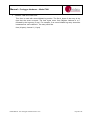
2.1
Programming Overview
The PROLOGGER is a microprocessor based device designed to be programmed using
Unidata’s STARLOG Software Package (Version 3). This package, designed to run on IBM PC
or compatible computers, creates and implements instructions that control the logger.
Through a series of windows, the STARLOG Software Package allows you to define how and
when the PROLOGGER records, what channels to record and what signal types to measure.
These definitions are compiled by the package into a list of instructions to be interpreted by the
PROLOGGER.
[The PROLOGGER must be programmed before it will record/log or display readings.]
The STARLOG Software generates a set of instructions to program the PROLOGGER. These
instructions are explained in the STARLOG Programmer’s Supplement (6201).
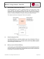
2.2
How the PROLOGGER Operates
The PROLOGGER must be .initialised. before it can be used. This is done automatically when
you load a scheme. Alternatively, you can manually initialise the device (see PROLOGGER
Initialisation on page 30). Note that when delivered, the PROLOGGER is shutdown to conserve
batteries. It must be initialised before use.
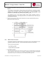
The PROLOGGER switches on once per scan. You must specify the scan rate. It performs
three operations each time it is switched on: scanning, inter-log analysis, and RS-232 comms
check. It then switches off. This sequence occurs every scan interval. It performs a fourth
operation, logging,
at an interval you specify. These operations are described below.
• Scanning
Scan rates, which can be from 125 milliseconds to 5 minutes, determine how frequently the
logger switches on. When it switches on, the logger scans its input signals. These signals,
called the hardware values, are recorded in the PROLOGGER memory. The hardware values
are updated in the logger memory every scan.
• Interlog Analysis
After scanning the input signals the logger program performs an inter-log analysis of the
hardware values, storing the analysed values in a different part of the logger.s memory referred
to as the Register. The inter-log analysis includes: averaging and storing maximum, minimum
and raw values. For example, if a certain channel is programmed to store maximum values of its
input, the logger will check to see if the hardware value is higher than the value already stored
in the Register. If so, it will update the Register. If not, then it changes nothing and goes to the
next instruction. The Register is used to store data between log intervals.
• RS232 Comms
When the scan occurs at a log interval, the logger program records data found in the Register
into another part of its memory. Here, the data remains until the logger is unloaded (or until the
entire memory storage space is filled, then earlier stored data may be overwritten when recent
data is logged).
Unidata Manual - 7001 Prologger Hardware Issue 2.1.doc
Page 8 of 53
Manual – Prologger Hardware – Model 7001
2.3
Input Signals
The PROLOGGER has 22 channels for input signals. These are divided into:
• Sixteen analog channels with 16-bit resolution. These can be in any combination of up to
16 single-ended or 8 differential voltage inputs. These channels accept signals from ±5
millivolts full-scale to ±5.00 volts full-scale.
• Two high speed serial ports (bi-directional synchronous, eight 16 bit channels on each).
• Four counter input channels (16-bit resolution).
• Two sense input channels (used for LOG START and SDI-12 signals).
The PROLOGGER has a number of operating modes for its analog inputs. Analog inputs are
available as low resolution (8 bit, a0 . a15) or high resolution (16 bit, A0 . A15) all with
programmable gain settings. (See PROLOGGER Configuration Table on page 47.)
For more about inputs see Installation and Connection on page 23.
[Note: To save power the PROLOGGER only measures signals on channels specified in the
scheme. If you load a scheme that only specifies a single channel, the remaining channels are
not scanned. If you want to scan signals on all channels, you must load a scheme that specifies
all channels.]
2.3.1
Instruments
To complement the PROLOGGER, a range of low power instruments and sensors is available.
They are designed for direct connection to the PROLOGGER and can use the PROLOGGER.s
battery or their own power supply.
The PROLOGGER has a broad input range. This means that instruments such as
thermocouples, pyrometers, RTDs (like the PT100), strain gauge pressure transducers,
precision thermistors and frequency derived signals can generally be connected without
amplification or signal conditioning.
2.4
Outputs
The PROLOGGER has two outputs and two power sources for external instruments. The
outputs have a wide range of uses, for example they can be used to set off an alarm or switch
on an external device.
The four user power sources described in the PROLOGGER Configuration Table are:
• +12 Volts DC unregulated.
• -12 Volts DC unregulated.
• +10 Volts regulated (reference).
• +5 Volts DC regulated, scan synchronised.
2.5
Memory Capacity
The logging duration of the logger depends on the scheme. It is calculated by the software once
the scheme is created (see Scheme Information menu). The calculation includes the following:
Number of Days = (512 - 8) * 1024 * LI/1440 * 1/LS
Unidata Manual - 7001 Prologger Hardware Issue 2.1.doc
Page 9 of 53
Manual – Prologger Hardware – Model 7001
LI = Logging Interval (in minutes).
LS = Log Size in bytes.
1024 = The number of bytes in a kilobyte.
1440 = The number of minutes in a day.
2.5.1
Log Size
The Log Size is the sum of bytes used per channel. The bytes used per channel varies
depending on the Log Action (raw reading, totalise to 1 or 2 bytes, etc.) and the capacity of the
channel. A counter channel may use from 1 to 4 bytes, a serial channel is usually 2 bytes, and
an analog channel may use 2 bytes (high resolution) or 1 byte (low resolution).
For example: A typical weather station logging raw readings for wind speed (1 byte),
temperature (1 byte), solar radiation (1 byte) and relative humidity (1 byte) every five minutes in
a 512k PROLOGGER would theoretically record for:
Number of Days = (512 - 8)* 1024 * 5/1440 * 1/4 = 448
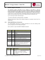
2.6
Status Indicators
The PROLOGGER has four LED indicators which flash briefly each scan (5 seconds) to show
the status of the battery and logging scheme.
2.6.1
Battery Status LEDs
The top two indicators (labelled BATTERY) show the internal battery status (see Battery Status
Indicators on page 20).
2.6.2
Scheme Status LEDs
When the PROLOGGER has been programmed with a Scheme (using Version 2 Software) the
lower two indicators show the status of the Scheme operation.
LED On
Description
Waiting to be unloaded.
Waiting for input signals to be connected.
State
Stopped
Primed
Green
Connected to signals and waiting to begin
logging.
Primed
Green & Red
Actively recording.
Logging
Red
(No Scheme loaded.)
(Invalid)
None
Unidata Manual - 7001 Prologger Hardware Issue 2.1.doc
Page 10 of 53
Manual – Prologger Hardware – Model 7001
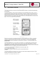
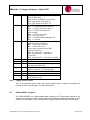
2.7
The Display and Keyboard
The PROLOGGER has a 64 character Liquid Crystal Display (LCD) and an eight key operator
keyboard.
The Display may be activated by pressing the ON key. The Display will turn
OFF automatically after a delay of 20 seconds (when no further keys have been pressed).
[While the Display is active, the PROLOGGER is in high power mode and uses about 100 times
more battery power than in normal scanning mode.]
2.7.1
Keys Definition
ON
SCHEME
CONFIG
ENTER
Up/Down
Arrows
Left/Right
Arrows
2.8
Activate display and display the first entry of the STATUS LIST.
Displays the first entry of the SCHEME LIST.
Displays the first entry of the CONFIG LIST.
Used only in the CONFIG LIST to save the current SETUP entry or
perform the current SETUP action.
Scroll UP cor DOWN dthe current list entries.
Adjust the current CONFIG entry UP in value f or DOWN in value e .
Used only in CONFIG LIST.
Using the Keyboard and Display
The display shows three lists of useful information.
STATUS LIST
SCHEME LIST
CONFIG LIST
Lists information about the status of battery and channel readings (unscaled).
Lists details of the current Scheme composed using the STARLOG Software
V3. This is normally blank unless a Scheme has been loaded.
Lets you adjust some logger configuration parameters (change the
scan rate) and execute some useful commands (such as, setting the
logger to the ‘sleep mode’).
[Warning: Saving altered Setup Entries using the Enter key will cause data stored in
memory above 64K to be lost.]
2.8.1
Selecting a Display List and List Entry
Whenever the ON, SCHEME or CONFIG keys are pressed, the first entry in the Status, Scheme
or Config list is displayed. The ON key will also turn the Display ON if not already on.
By pressing the scroll keys, you display the next Entry in the list (DOWN key) or the previous
Entry (UP key).
[Entries may be one or two lines, therefore the scroll keys will move the display UP or DOWN
one or two lines, depending on whether the Entry is two lines or not.]
Unidata Manual - 7001 Prologger Hardware Issue 2.1.doc
Page 11 of 53
Manual – Prologger Hardware – Model 7001
2.8.2
Auto Key Repeat
When a key is held down, it automatically repeats. This is a quick way to scan up or down a list
of display entries. Releasing the key stops the repeat mode.
2.8.3
Adjusting a Config Entry
To alter a logger Config Entry, scroll to the desired Entry in the Config List and use the Adjust
keysto adjust the Config Entry to the required settings, then press ENTER to save the new
setting permanently. If you do not want to save the Config Entry, press any other key (or no
keys at all).
[Warning: Pressing the Enter key while displaying a Config Entry with the message ....use &
ENTER. on Line 2 will cause data stored in memory above 64K to be lost.]
2.8.4
Commands in the Config List
Some entries in the Config List are simple commands, they do not use the Adjust keys34and
they do not cause loss of memory when executed (when ENTER is pressed). A useful
command ‘TURN DISPLAY OFF’ Is the first entry in the Setup List. Therefore, whenever you
have finished viewing the display, press CONFIG, and then ENTER keys.
[The display will automatically turn OFF anyway after 20 seconds if no keys are pressed.]
2.8.5
Using a PIN# (Password)
The PROLOGGER is fitted with a keyboard and display. This enables you to configure various
functions of the logger without a computer. To ensure that only authorised users alter the
operation of the logger, an optional 4-digit PIN# (personal identification number) may be
entered. The factory default for the PIN# is 0.
To change this PIN#, turn the display ON and then press CONFIG. Press the down arrow until
CHANGE PIN# appears in the display. Press the left arrow key to select the digit and then the
up or down arrow to alter the digit. Once you have selected a suitable 4 digit number, press
ENTER. It is now impossible to change important configuration settings until the PIN# is reentered.
Once a PROLOGGER has been protected by a non-zero PIN#, you must re-enter the correct
PIN# before altering a configuration via the keyboard.
1. Press ON to switch the display on.
2. Press CONFIG.
3. Press the down arrow until ENTER PIN# appears.
4. Select the correct 4-digit code (using the arrow keys) and press ENTER.
5. You can now alter the logger.s configuration.
To change the PIN#, you must enter the old PIN# first. A PIN# of 0 means that all settings may
be changed without PIN# validation (default).
[If you forget the PIN#, the PROLOGGER will operate normally but you will not be able to use
the keyboard configuration facility until the PROLOGGER is returned to UNIDATA for service.]
Unidata Manual - 7001 Prologger Hardware Issue 2.1.doc
Page 12 of 53
Manual – Prologger Hardware – Model 7001
2.8.6
Displaying the Scheme List
The Model 7001 PROLOGGER has a four line liquid crystal display (LCD) and eight key
keyboard.
Using the Version 3 Software you can set-up the PROLOGGER to display the actual values
being recorded by connected transducers. This Scheme Display List contains information
similar to the Scheme Test Mode screen. A one-line display entry is provided for each Scheme
Test Mode entry. Four entries (lines) are shown on the display at one time.
When you press the up/down scroll keys the display moves up/down this list one line at a time.
To view the readings of each transducer:
[The display turns OFF after 20 seconds, if no keys are pressed.]
[If the instrument being displayed uses a non-linear correction formula (such as a thermistor or
wind direction) then the uncorrected (raw) mV reading will be displayed without units.]
2.9
Differences with Model 7000 Macro Data logger
2.9.1
Input Signals
The following inputs are different from the Portable Data logger:
Pin
Model 7001
Model 7000
17
Continuous Battery
Unused
19
Sense 1/SDI
Unused
Unidata Manual - 7001 Prologger Hardware Issue 2.1.doc
Page 13 of 53
Manual – Prologger Hardware – Model 7001
3.0
SPECIFICATIONS
This chapter lists the physical and performance specifications of the PROLOGGER.
Material:
Size:
Weight:
Operating Temp:
Scan Rate:
Log Interval:
Memory:
Time Clock:
Analog Inputs:
Counters:
STARBUS:
SDI-12:
Controls:
Computer I/O:
Processor:
Battery Life:
Flat Battery Shutdown:
Instrument Power:
Grey, high impact rigid PVC.
211 x 108 x 81mm (H x Wx D).
2 kg including battery.
-20°C to 60°C, not affected by humidity.
0.125 second to 5 minutes - programmable.
0.125 second to 1 week - programmable.
Low power CMOS RAM 512k (standard).
Crystal regulated, ±10 seconds per month.
16 channels, 16-bit resolution.
Unipolar or Bi-Polar, differential or single ended.
4 channels, 16-bit resolution.
2 high speed serial lines with eight channels on each,
16 bits, bi-directional, synchronous data & clock.
Optional 1200 Baud instrument channel.
2 channels, 1 CMOS output.
1 uncommitted open collector output.
Full duplex, serial, RS-232C, baud rates:
300/1200/2400/4800/9600/19200/38400/76800.
8 bit, 80C31 micro controller, 14.7456 MHz.
Alkaline 1 year (typical), or rechargeable NiCad.
5.6 Volts.
+5V DC regulated 100mA.
+6.5V DC unregulated, 1mA continuous.
+10V DC regulated, 100mA programmable duty cycle (PDC).
+12V DC unregulated, 200mA, PDC.
-12V DC unregulated, 50mA, PDC.
Signal Specifications
Counter Channels: DC to 20 kHz potential free contact or
0.5 V DC digital input.
Analog Channels: Voltage input in four programmable ranges:
-5.00 to +5.00 V, 155µV resolution.
-500 to +500 mV, 15.5µV resolution.
-50 to +50 mV, 1.55µV resolution.
-5 to +5 mV, 155nV resolution.
Input Impedance: >1 MΩ
Recommended Source <10 kΩ
Drive Impedance:
Unidata Manual - 7001 Prologger Hardware Issue 2.1.doc
Page 14 of 53
Manual – Prologger Hardware – Model 7001
4.0
POWER SUPPLY
This chapter describes the uses of internal and external power supplies for the PROLOGGER. It
also describes the low battery shutdown feature. The PROLOGGER is powered by an internal
battery. External power sources can be used as an alternative supplies or to recharge batteries
(NiCad and Sealed Lead Acid only).
A battery must remain connected at all times to protect data stored in memory. Provision is
made for fitting a Lithium back-up battery to protect memory storage if the main battery is
removed or fails.
4.1
Internal Battery Pack
The PROLOGGER is powered by its own internal power supply in the form of a battery pack
(usually supplied with each logger). Alkaline (Model 6910A) and NiCad (Model 6910B) battery
packs are available. The battery pack is located in the base of the logger housing and
connected via a three-way socket to the logger.
The PROLOGGER requires a single battery voltage of 6.5 to 10 V DC.
Battery life varies anywhere from a few weeks up to 2 years depending on the logging project
(see below).
This section covers:
•
•
•
•
4.1.1
Battery life.
Battery connections.
Battery replacement.
Recharging a NiCad battery pack.
Battery Life
The PROLOGGER battery life is influenced by five factors:
•
•
•
•
•
logger scan rate.
logger program run time.
External instrument power requirements.
Display usage.
Computer communication (RS-232).
Formula for Determining Battery Life
The following calculation will determine the battery life for UNIDATA battery packs (Model
6910A):
Life (days) = [ST/(RT+35)] * 3300
ST = Scan Time (seconds)
RT = Run Time (milliseconds)
… where external instrument load does not exceed 20mA.
Unidata Manual - 7001 Prologger Hardware Issue 2.1.doc
Page 15 of 53
Manual – Prologger Hardware – Model 7001
The run time is determined by examining Address 1 of the PROLOGGER (Block 0, locations 1
and 2), where the program run time is saved.
[6910A battery packs have a maximum life of 3 years.]
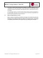
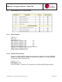
Battery Life Estimation Tables
The following table details the estimated battery life from loggers with various scan rates and
battery types. This table assumes a program run time of 12 milliseconds (approximately 40
instructions).
0.25
Model 6910B
Life (days)
12
Model6910A
Life (days)
16
1
30
66
5
40
330
10
40
660
Scan Rate
Model 6910A . 10 Ah Alkaline Battery Pack.
Model 6910B . 4 Ah Nickel Cadmium Battery Pack.
4.1.2
Battery Pack Connections
The Model 6910 battery packs are manufactured with a 3-way socket connector that plugs into
the Model 7001 PROLOGGER.
Users who manufacture their own replacement battery packs may purchase connectors from a
Molex dealer or simply re-use the wire & connector from the old battery pack. The connector
type is Molex brand 050-57-9403 70066-0177 shell with type 016-02-1125 71851-0224 crimp
terminals.
4.1.3
Replacing a Battery Pack
All recorded data will be lost when the battery pack is disconnected (unless the auxiliary battery
is installed (see page 21). Ensure the PROLOGGER has been unloaded before replacing the
battery.
To replace a battery pack:
1. Remove the PROLOGGER lid by unscrewing the six lid screws.
2. Depress the small retaining clip securing the battery plug and disconnect the battery cable.
3. Lift out the black metal battery retaining plate and remove the used battery pack.
4. Insert a new battery pack and replace the metal retaining plate making certain not to crush
the battery wires.
5. Reconnect the new battery and the PROLOGGER will begin operating.
6. Replace the lid into PROLOGGER base and tighten the six lid screws. The PROLOGGER will
not be damaged if battery wires are accidentally reversed.
Unidata Manual - 7001 Prologger Hardware Issue 2.1.doc
Page 16 of 53
Manual – Prologger Hardware – Model 7001
ENVIRONMENT FRIENDLY - UNIDATA uses only mercury-free alkaline cells in battery packs.
UNIDATA or your battery manufacturer will accept battery packs returned for recycling.
4.1.4
Recharging NiCad Battery Pack
The NiCad Battery Pack can be recharged by a mains power pack or a solar powered recharge
system. You can also recharge a battery pack on site using an external power source. (See the
next section.)
4.2
External Power Supply
An external power source can be connected to the PROLOGGER. External power can be used
with an Alkaline or NiCad battery pack as a backup power source or simply on its own.
A mains power pack and a solar power pack are available from UNIDATA.
• The supply voltage to the PROLOGGER must be maintained at all times to ensure
correct logger operation and data integrity. (See optional Auxiliary Memory Back-up
Battery on page 21.)
The voltage to the logger must be in the range of 9 V to 20 V and able to supply a load of 100
mA peak (increasing to 500 mA when recharging a battery).
4.2.1
Connecting an External Power Supply
To install an external power supply:
1. Connect +ve to pin 16 of the INPUT SIGNALS socket (terminal 1 of the Field Termination
Strip).
2. Connect -ve (common) to pin 34 of the INPUT SIGNALS socket (terminal 2 of the Field
Termination Strip).
•
4.2.2
Pins 50 - EXT Power and 51 - GND on the 7001C Field termination Strip are generally
used for charging external batteries using a solar panel.
Recharging Batteries
With a NiCad battery pack installed a PROLOGGER can be recharged from a solar panel,
mains power pack or other DC power source. The input voltage should be between 11V and
20V.
•
4.3
NiCad Battery Packs require several charge/discharge cycles before their full charge is
retained. Therefore ensure the PROLOGGER has been fully charged (connected to
solar recharge or mains power pack) then left to discharge at a high scan rate.
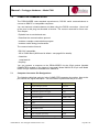
Battery Status Indicators
The PROLOGGER measures its internal battery voltage every scan. If the battery voltage falls
below certain preset levels, the Battery Status LEDs on the front panel will change state.
Unidata Manual - 7001 Prologger Hardware Issue 2.1.doc
Page 17 of 53
Manual – Prologger Hardware – Model 7001
GREEN
RED
BATTERY STATUS
ALKN
NiCAD
LCD
DISPLAY
On
Off
Battery OK
>7.2V
>7.2V
Ok
On
On
Battery Low(Replace
soon)
<7.2V
<7.2V
Low
Off
On
Battery Flat(Replace
immediately)
<6.6V
<7.1V
Chg
Off
Off
Not Operating ("Sleep"
or"Shutdown" Mode)
<6.2V
<7.0V
Bad
•
4.4
Whenever an external power source greater than 11V DC is connected to the logger, the
internal battery is bypassed (and/or recharged). The logger operates from the external
power, but will automatically use the internal battery if external power falls below 11V DC
or fails altogether.
Monitoring Battery Voltage
The most recent battery voltage measurement is stored in the logger memory and can be
displayed or logged.
The PROLOGGER saves the voltage measurement at Address 236 (Internal Channel I2, also
called, .Batt., see page 32). Use Test Mode to display the internal channels.
4.5
Flat Battery Shutdown
The logger also monitors the battery voltage when in sleep mode. If the voltage falls to a level
that could cause faulty operation, the logger enters shutdown state and will not scan,
communicate with a computer or activate the display. In addition, all equipment power loads are
disconnected (counter channels and pin 18 continuous power) to preserve memory.
The Flat Battery Shutdown voltage limit is 5.6V.
4.5.1
Saving Memory
A logger in Shutdown or ‘Sleep’ mode will preserve its memory for many weeks. To recover
information stored in the logger:
Connect a computer to the logger and attempt to ‘Unload’ it.
If the logger was in sleep mode, it will wake-up and unload normally. If it was in shutdown mode,
connect an external power source to the logger (such as a new battery pack, see page 18 for
details). The logger will wake-up and unload normally.
Unidata Manual - 7001 Prologger Hardware Issue 2.1.doc
Page 18 of 53
Manual – Prologger Hardware – Model 7001
•
4.5.2
The external power must be connected without disconnecting the internal ‘Flat’ battery
(unless the optional memory back-up battery is installed). Follow the procedure in
Connecting an External Power Supply on page 19.
Auxiliary Memory Back-up Battery
An optional Lithium battery (Model 6909A) can be installed to provide memory back-up power
when the main battery pack is removed or fails completely. The battery type is a 3.4VAA lithium
cell with wire leads (SAFT LS14250 or similar).
The status of the auxiliary battery is monitored by the logger. If the battery requires replacement
(or is not installed) an asterisk (*) is displayed adjacent to the main battery status.
To check auxiliary memory back-up battery:
1. Press the ON key firmly. The following is displayed:
PROLOGGER 900
V033.00 BAT=OK *
2. This indicates the auxiliary battery is either not installed or needs replacement.
In all loggers the auxiliary memory back-up battery status is indicated in Bit 6 of Register 33
(see section 8.2.1).
4.6
Internal Battery Charger
The PROLOGGER has an inbuilt battery charging circuit designed for continuous recharging of
NiCad and Sealed Lead Acid batteries as well as providing regulated power to the logger when
operating from external power.
4.7
Automatic Battery Type Detection
The PROLOGGER automatically detects which type of battery is installed and sets the voltage
thresholds accordingly. The logger also enables the battery charging circuit when a NiCad
battery is installed.
ALKLN or NiCad will be displayed on the LCD according to which type of battery is installed.
•
4.8
If external power is used and no battery pack is installed, the LCD will indicate ALKLN.
The Input Signals Connector Pin-out
The table on page 24 lists each pin in the INPUT SIGNALS connector by number. Next to the
pin number is a description of the signal for which this connection is designed. The last column
lists the high resolution channel mnemonic used by STARLOG to refer to this connection.
Unidata Manual - 7001 Prologger Hardware Issue 2.1.doc
Page 19 of 53
Manual – Prologger Hardware – Model 7001
5.0
INSTALLATION & CONNECTION
This chapter provides information necessary to install a PROLOGGER. It includes:
· A list of the connections of the INPUT SIGNALS connector.
· Signal specifications for each connection.
· How to initialise a PROLOGGER.
5.1
Locating the logger
The PROLOGGER may be installed in nearly any environment with the following
provisos:
· It should not be exposed directly to the weather. If it is to be used externally, it should
be housed in a weatherproof enclosure.
· It should be mounted away from electrical noise sources (such as electrical contactors
and radio transmitters). In all cases signal leads should be shielded and kept as short
as possible.
Wherever possible, install the PROLOGGER in a protected location exposed to the
least temperature extremes. This will increase the battery life, and improve clock and
signal measurement accuracy.
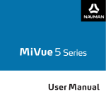
5.2
Instrument Connection
You connect instruments to the PROLOGGER via the 37-pin socket located on the
logger’s front panel and labelled INPUT SIGNALS. For ease of use you can plug a
Field Termination Strip into this connector. Each input is referred to as a channel in the
STARLOG Software Package.
•
Field Termination Strip
This extends the INPUT SIGNALS connector to a row of numbered screw terminals.
The Field Termination Strip (Model 7100C) and its manual (supplement 7012) are
available from UNIDATA.
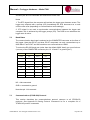
The pinouts of the INPUT SIGNALS CONNECTOR is shown below.
The following table lists each pin in the INPUT SIGNALS connector by number. Next to
the pin number is a description of the signal for which this connection is designed. The
last column lists the high resolution channel mnemonic used by the STARLOG
Software to refer to this connection.
Pin
Signal Description
1
Analog ground
2
Analog input
Unidata Manual - 7001 Prologger Hardware Issue 2.1.doc
Channel
A1 (A1+ve)*
Page 20 of 53
Manual – Prologger Hardware – Model 7001
3
Analog input
A3 (A3+ve)
4
Analog input
A5 (A5+ve)
5
Analog input
A7 (A7+ve)
6
Analog input
A9 (A1-ve)
7
Analog input
A11 (A3-ve)
8
Analog input
A13 (A5-ve)
9
Analog input
A15 (A7-ve)
10
Sense input BIT 3 (Log Start, MASK 8)
SENSE 0
11
16 bit counter input (20kHz)
C0
12
16 bit counter input (20kHz)
C2
13
High Speed Synchronous Serial Port Clock
(TTL level input and output)
HSIO Clock 1
14
High Speed Synchronous Serial Port Clock
(TTL level input and output)
HSIO Clock 0
15
Control, Open collector output, 30V, 100mA
drive, 20ms pulse width
OUT 1
16
External power +12V (or recharge)
Power Input
17
+6V continuous power for external
instruments (1mA maximum)
Micro Power
18
Scan synchronised +5V regulated UPS or
HSIO Sync (@30mA max)
Sync Power or
HSIO Sync
Pin
Signal Description
Channel
19
Sense input BIT 1 (MASK 2)
SENSE 1 /SDI12
20
Analog input
A0 (A0+ve)
21
Analog input
A2 (A2+ve)
22
Analog input
A4 (A4+ve)
23
Analog input
A6 (A6+ve)
24
Analog input
A8 (A0-ve)
25
Analog input
A10 (A2-ve)
26
Analog input
A12 (A4-ve)
27
Analog input
A14 (A6-ve)
28
Digital ground
Digital ground
29
16bit counter with prescale (20kHz)
C1
Unidata Manual - 7001 Prologger Hardware Issue 2.1.doc
Page 21 of 53
Manual – Prologger Hardware – Model 7001
30
16bit counter with prescale (20kHz)
C3
31
High Speed Synchronous Serial Data Port
(TTL level input and output)
HSIO data 1
32
High Speed Synchronous Serial Data Port
(TTL level input and output)
HSIO data 0
33
Control, Open collector output, 30V, 100mA
drive, 20ms pulse width
34
Power ground
Power ground
35
+10V regulated user power source
User power
36
-12V, 5mA unregulated user power supply
User power
37
+12V, 200mA unregulated user power supply
User power
*The channel assignments for inputs in brackets refer to differential signals.
Unidata Manual - 7001 Prologger Hardware Issue 2.1.doc
Page 22 of 53
Manual – Prologger Hardware – Model 7001
5.2.1
Log Start Sense
Normally, the PROLOGGER only begins to record when an instrument is connected via
the INPUT SIGNALS input. To sense this condition, Pin 10 (Log Start Sense 0) of the
INPUT SIGNALS socket is grounded (connected to Pin 28). The PROLOGGER
program may then sense this condition by the BJMPN 32,#8,Branch Label instruction
which branches when the INPUT SIGNALS are not connected. See the description of
the startup.INCLUDE file in the Programmer’s Supplement (No. 6201) for further
information.
•
5.2.2
Warning: The STARLOGGER will not begin recording unless the LOG START Sense is
connected to ground (Pin 28). LOG START is automatically connected to ground when
the Model 7100 Field Termination Strip is used.
Analog Inputs
Analog inputs can be used as low resolution (8 bit) or high resolution channels (16 bit).
Their usage depends how you refer to the input in the STARLOG software. The
software interprets analog inputs as low resolution channels when you refer to them as
a0 . A15 and high resolution channels when you refer to them as A0 - A15.
All analog channels are programmable to carry a signal in one of four ranges:
-5.00 to 5.00V
155 V resolution
-500 to 500mV
15.5 V resolution
-50 to 50mV
1.55 V resolution
-5 to 5mV
155nV resolution
Input impedance (when the logger is active) is greater than 1M . Load impedance
(when the logger is inactive) for signals less than 500 mV is greater than 1M . For
signals greater than 500mV it is 10k . The recommended source drive impedance is
<10k .
Analog channel calibration coefficients are stored in the configuration table (see page
47 for details).
5.2.3
Counters and Digital Inputs
Counter and Digital inputs are DC
inputs suitable for 20 kHz potential
free contacts or 0.5V to 0.12V DC
digital input.
Unidata Manual - 7001 Prologger Hardware Issue 2.1.doc
Page 23 of 53
Manual – Prologger Hardware – Model 7001
Maximum pulse rate to the counters is 20 kHz. Pulse rates must also be related to scan
rate, to ensure counters do not overflow before being scanned by the PROLOGGER.
5.2.4
User Power Sources (UPS)
The User Power Sources (Pins 18, 35, 36, 37) are intended to power instruments
associated with the PROLOGGER. The full load output capability is 350mA in pulsed
mode and 175mA (50% duty cycle) in continuous operation. The standing battery drain
with the UPS switched ON (and no external UPS load) is 15mA.
The Scan Synchronised UPS (Pin 18) switches on and off in sync with the logger scan.
Any loads connected to these outputs will contribute to the drain on the PROLOGGER
battery (and reduce battery life).
The other User Power Sources (Pins 35, 36, 37) are programmmed to switch on and
off by setting three variables (Prescan, Ontime and Offtime) in the PROLOGGER
Configuration Table. See PROLOGGER Configuration Tables on page 47 details.
5.2.5
High Speed Serial Ports
There are two serial ports:
Port 0
Pin 13 (Clock 1)
Pin 31 (Data 1)
Port 1
Pin 14 (Clock 0)
Pin 32 (Data 0)
Pin 18 +5V sync signal
These ports are read each logger scan. The Sync signal (Pin 18) is used to indicate to
the remote equipment that a logger read scan is about to begin. This signal is used to
load the serial shift register(s) in the remote equipment in preparation of being read.
•
The first data bit LSB must be present on the Data (0/1) signal within 7ms after the Sync
signal.
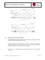
Serial transfer rate is 50 microseconds per bit with a 30 microsecond gap between
each byte. See the timing diagrams for Serial In and Serial Out below.
•
Every 1mS a logger interrupt sequence adds a 50 microsecond delay to the serial
transfer sequence. Transfer starts with the least significant bit of the least significant byte
and each clock reads the next most significant bit.
Unidata Manual - 7001 Prologger Hardware Issue 2.1.doc
Page 24 of 53
Manual – Prologger Hardware – Model 7001
5.3
SDI-12 Serial Digital Interface (optional)
The PROLOGGERs support the U.S.G.S. SDI-12 standard for serial data interchange
between the logger and intelligent instruments.
SDI-12 is implemented as an alternate use of Sense 1 (Pin 19). Up to ten SDI-12
compatible instruments may be connected to this bus. Programming the SDI-12
interface is supported in the STARLOG Version 3 Software.
See Appendix D - Using the SDI-12 Interface details on how to use the SDI-12
Interface.
Unidata Manual - 7001 Prologger Hardware Issue 2.1.doc
Page 25 of 53
Manual – Prologger Hardware – Model 7001
5.4
PROLOGGER Initialisation
The STARLOGGER is normally stored and delivered to you in sleep mode to conserve
batteries. You must load a scheme into the logger before it can be used.
In normal use, the PROLOGGER will not require initialisation. If however, the logger
does not appear to scan at the correct rate, it may need re-initialization.
Any of the following actions will (re)initialise the logger:
· Loading a Scheme into the logger.
· Executing the ‘RESET LOGGER’ command in the Config List.
· Using the ALT-I command in Diagnostics. (See the STARLOG Software Package.)
· Disconnecting, then re-connect the battery after a ten second delay. WARNING: data
stored in memory will be lost.
· Adjusting and saving any of the Config Entries.
During initialization, the logger’s firmware and Configuration Table is check-summed to
confirm its integrity. The Scan Counter is set to the logger Scan Rate and other
housekeeping functions performed.
See the STARLOG User’s Manual for more information.
6.0
INTERNAL CHANNELS
The PROLOGGER has four internal channels. These are presented as high resolution
values (signed 16 bit) in Register Addresses 232 to 239 as detailed below:
Register
Address
Name
Description
I0
(Temp)
I1
(10V)
I2
(Batt)
logger Temperature (0.1221°C per
bit)
232
10V reference (1.221 mV per bit)
234
logger battery (or supply) voltage
(1.221 mV per bit)
236
5V scan synchronised reference
voltage (1.221 mV per bit)
238
I3 (5V)
Unidata Manual - 7001 Prologger Hardware Issue 2.1.doc
Page 26 of 53
Manual – Prologger Hardware – Model 7001
The values of these internal channels are available for recording (logging) or use in
computations in the User Log Program. Typical uses may be to provide high accuracy
corrections to bridge measurements (strain gauge/PT100 etc.) referenced to the 10V or
5V supplies.
The temperature (which is in thermal contact with the Analog ground point adjacent to
the Input Signal connector) can be used to provide cold junction compensation for
thermocouples connected to the Input connector.
6.1
Battery Voltage Monitor (I2, .Batt.)
Battery voltage is automatically monitored by the logger and recording will cease if the
battery falls below a defined threshold (the logger goes into sleep mode). The threshold
is defined in the Configuration Table (see page 47). The battery state is also displayed
on the Battery Status LEDs while the logger is operating (see page 20 for details).
Unidata Manual - 7001 Prologger Hardware Issue 2.1.doc
Page 27 of 53
Manual – Prologger Hardware – Model 7001
7.0
COMPUTER COMMUNICATION
The PROLOGGER uses standard asynchronous, RS-232 serial communications to
connect to IBM PC or compatible computers.
You can load and unload schemes and data using the RS232 connection . About half
of the pins in this plug are allocated a function. The rest are reserved for future use.
This chapter:
· Explains how to set the baud rate.
· Describes the communications protocol.
· Includes a sample communication program.
· Includes a table listing pin allocations.
The communication format is:
· RS-232C compatible.
· 300 to 76800 baud (9600 baud is default - see page34 for details).
· 8 data bits.
· 1 stop/start bit.
· No parity.
You can connect a computer to the PROLOGGER via the 25-pin socket (labelled
COMPUTER) located on the logger.s front panel. Model 6602A 25-25 pin and Model
6602I 25-9 pin cables are available from UNIDATA.
7.1
Computer Connector Pin Designations
The following table lists each pin in the COMPUTER connector by number. Next to the
pin number is a signal description. The last column explains how the pin is used.
Pin
Signal Description
Usage
1
Signal and logic ground
Ground
2
Serial data signal to logger
RxD
3
Serial data signal from logger
TxD
4
RTS from computer
RTS
6
DSR from logger
DSR to CPU
7
Signal Ground
GND
10
Mode
15
Baud Rate Select (See section 7.2.)
16
Baud Rate Select
17
Baud Rate Select
20
from computer (not used)
DTR
25
Remote Telemetry Control from logger
OUT 0
Unidata Manual - 7001 Prologger Hardware Issue 2.1.doc
Page 28 of 53
Manual – Prologger Hardware – Model 7001
All other pins are not connected and reserved for future use.
Notes
1. The RTS signal from the computer will activate the logger even between scans. The
logger may respond with a prompt (CR) immediately the RTS becomes true or wait
until the next scan (depending on communication mode settings).
2. CTS signal is not used to synchronise communications between the logger and
computer, this is achieved by the logger prompt (CR). The DSR is true whenever the
logger scan is active.
7.2
Baud Rates
The communication baud rate is selected on the COMPUTER connector on the face of
the logger. Note that PC/XT and slow PC/AT computers can only communicate up to
9600 baud. Fast PC/AT and 386 machines can communicate at 19200.
To select the RS-232 baud rate (other than the default 9600* baud) you must link one
(or more) of the COMPUTER connector pins 15, 16 and 17 to ground (pin 7).
Pin 15
Pin 16
Pin 17
Baud Rate
GND
NC
GND
300
NC
GND
NC
1200
NC
GND
GND
2400
GND
GND
NC
4800
NC
NC
NC
9600*
NC
NC
GND
19200
GND
NC
NC
38400
GND
GND
GND
76800
NC = Not connected.
GND = connected to ground.
Note that pin 14 is reserved.
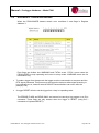
7.3
Communications (STARLOG) Protocol
This section describes the communications protocol common to all STARLOG
products. See Appendix B Starlog Protocol Command List for a complete list of
STARLOG protocol commands.
Unidata Manual - 7001 Prologger Hardware Issue 2.1.doc
Page 29 of 53
Manual – Prologger Hardware – Model 7001
7.3.1
Scan Synchronised RS-232 Communication
At the end of every scan (5 seconds usually) the logger will check to see if the
computer interface is connected. If the interface is connected, the logger sends a
prompt to the interface (host computer). This prompt is an ASCII asterisk followed by a
carriage return (CR).
The logger then waits 0.5 second for a request from the host computer. If no request is
received by the logger, the logger powers down (switches off) until the next scan (5
seconds usually).
While the logger is communicating with the computer, it will remain active (in high
power mode). However, any logger scans that are due will be processed
simultaneously with ongoing communications.
7.3.2
Non-Synchronised RS-232 Communication (default)
If the PROLOGGER is set to operate in non-synchronised mode the RS-232
communication protocol timing is slightly different.
The logger will immediately enter communications state (and send a prompt) whenever
the Request To Send (RTS) line becomes true (ON/HIGH). It does not wait until the
end of the next logger scan.
If a logger Scan occurs during RS-232 communications, the scan will be processed.
7.3.3
PROLOGGER Requests (Commands)
A PROLOGGER has three basic commands - GET, PUT and KILL. The (G)ET and
(P)UT commands only access the first 64K of memory.
For memory sizes greater than 64K, lowercase equivalents of these commands serve
as an extended protocol commands. That is, g performs an extended GET command.
All extended protocol commands require a checksum following the message.
If the logger receives an invalid command it will be ignored. Other commands are used
to maintain and initialise the Configuration Table (see page 47 for details).
See Appendix 7.3C - Starlog Protocol Command List for a complete list of STARLOG
Protocol commands.
GET {and (g)et} Commands
GAAAASS where G is the GET command, AAAA is the 16 bit address (MSB/LSB) and
SS is the number of bytes required. (Zero in the SS command corresponds to 256
bytes.) (AAAA is the command for a 16 bit address in the first 64K memory storage of
the Logger.)
Gaaaaaaaasssscccc
Where g is the get command, aaaaaaaa is the 32 bit start memory address
(MSB...LSB), ssss is the 16 bit number of bytes to transfer, and cccc is the 16 bit
checksum.
Unidata Manual - 7001 Prologger Hardware Issue 2.1.doc
Page 30 of 53
Manual – Prologger Hardware – Model 7001
To read 256 bytes from address 768 into the host computer the command is:
G030000
PUT {and (p)ut} Commands
PAAAASS
paaaaaaaassss...put data...cccc
similar to the GET command except that data is
sent to the logger immediately following the
command string.
cccc
the 16 bit checksum for the (p)ut command
includes the address, size and data fields (i.e.,
everything excpet the “p” command and the
checksum itself) and is sent MSB/LSB.
To reset the logger timer to zero, you will want to put zero into addresses
0004,0005,0006 & 0007. The command is:
P00040400000000
P
0004
04
00000000
is the put command
is the offset address (in the registers)
is the put data count
is the data to put
The data format for the GET or PUT is a continuous string of hexadecimal characters.
The first two characters correspond to the first byte requested or to be sent, the next
two characters is the second byte, and so on. The data string is terminated by a
carriage return.
A command to retrieve 16 bytes may appear as:
G000010
the returned data may appear as:
00112233445566778899AABBCCDDEEFFmmllCR
Where mmll = Get data checksum consisting of a 16 bit binary addition of all binary
data (not HEX representation) within the retrieved information (excluding the checksum
and CR). The checksum is sent as four HEX characters - mm = Most Significant Byte
and ll = Least Significant Byte.
Unidata Manual - 7001 Prologger Hardware Issue 2.1.doc
Page 31 of 53
Manual – Prologger Hardware – Model 7001
•
•
Two hex characters are always received or transmitted (most significant digit then least
significant digit) even though the number is smaller then 16. For example, 10 decimal is
sent or received as 0A.
GET or PUT may address any continuous segment of the memory.
(K)ILL command
K is the KILL command which directs the Data Logger to switch OFF until the next scan
cycle (usually 5 seconds).
A command to load location 2 with 0 then exit, would be:
P00020100K
•
After a GET command, the computer must wait until the Data Logger has sent the GET
data before a KILL is issued.
•
7.4
Sample Program
The following program written in Microsoft QBASIC communicates between the Data
Logger and an IBM PC or compatible computer.
7.4.1
Simple Interrogation Example
This sample program will issue a command to the Data Logger and display the
response from the logger. The commands must be valid commands (see above).
The “ON ERROR GOTO 140" statement is needed to trap (and ignore via RESUME
statement) any I/O errors that may occur as the Data Logger powers up and the RS232 signals lines change states.
The statement 70, sends the command to the logger. Notice that a “K” command (kill)
is appended to the operator request. This shuts the Data Logger down, immediately
after the request has been completed (to save logger battery power).
Try entering these commands:
G000008 (get 8 bytes from location 0)
G000502 (get 2 bytes from location 5)
G010010 (get 16 bytes (10 hex) from location 256 (Block 1, Location 0)
P00020188G000201(put 88 into location 2 and immediately gets the data)
Unidata Manual - 7001 Prologger Hardware Issue 2.1.doc
Page 32 of 53
Manual – Prologger Hardware – Model 7001
•
The maximum G (get) size is 127 (7F hex). This is limited by BASIC string length
maximum of 255 characters.
10
20
30
40
50
60
70
80
90
100
110
120
130
140
REM STARLOGGER - data transfer example
INPUT “Enter data logger command-”,A$
‘Get Command from operator
IF A$="" THEN END
‘Finish on c/r
OPEN “COM1:9600,N,8,1,CS0,DS0,CD0” FOR RANDOM AS #1
‘Open RS-232 to logger
ON ERROR GOTO 140
‘Trap I/O errors
INPUT #1,L$:IF INSTR(L$"*")=0 THEN 60
‘Wait for logger prompt
PRINT #1,A$;
‘Send command to logger
INPUT #1,L$
‘Get response from logger
PRINT #1,"K";
‘Send KILL to save battery
ON ERROR GOTO 0
‘Reset error trapping
CLOSE #1
‘Close RS-232 file (channel)
PRINT “Data Logger Response =”;L$ ‘Print result on terminal
GOTO 20
‘Go back to beginning
RESUME
‘Ignore I/O error
Unidata Manual - 7001 Prologger Hardware Issue 2.1.doc
Page 33 of 53
Manual – Prologger Hardware – Model 7001
8.0
PROGRAMMING THE PROLOGGER
This chapter describes programming techniques of and memory layout for the
PROLOGGER. The contents of this chapter will be useful to those who program and
test the logger using the test mode screens provided with the STARLOG Software
Package.
For those who use the STARLOG software, this chapter provides important details on
the PROLOGGER instructions used by the assembler. For complete programming
information consult the STARLOG Programmer.s Manual (No. 6201) included with the
STARLOG Software Package (Model 6300).
8.1
Memory Layout
The PROLOGGER uses CMOS memory for the:
· Logger Program - the scheme definition.
· Buffer Control Table - Storage of pointers controlling the Log Buffer.
· Hardware Registers - Storage of housekeeping registers.
· Log Buffer - from the end of the logger program to the end of memory for recording
measured data.
Unidata Manual - 7001 Prologger Hardware Issue 2.1.doc
Page 34 of 53
Manual – Prologger Hardware – Model 7001
8.2
Hardware Register Information
The hardware register information can be viewed in Test Mode or used by
programmers wishing to write their own unload and analysis programs. The table below
gives a description of each register numbered 0 to 255. For multiple byte registers the
convention used is . least significant byte to most significant byte. A byte may contain a
number from 0 to 255 (8 bits) and for calculating multiple byte numbers the first byte is
added to the second byte times 256 plus the third byte times 256 times 256, etc.
eg. The four byte number 1234 would give:
1+(2*256)+(3*256*256)+(4*256*256*256) = 67305985
Arithmetic instructions using 32-bit unsigned integers can represent values from 0 to
4294967295.
8.2.1
PROLOGGER Memory Assignments
The PROLOGGER operating the standard instruction set, has the following fixed
memory assignments in the Hardware Register:
(Pin xx) refers to a pin of the INPUT SIGNALS connector.
Address
0
Size
1
1
2
3
4
8
1
4
3
11
2
13
14
2
2
16
8
24
8
Address
32
Size
1
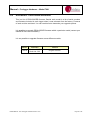
Description
Software Revision Number (33 onwards)
logger runtime in milliseconds (16 bit
integer)
Error flags (see Appendix A)
logger scan counter (32 bit integer)
Reserved
MSB of address (bits 8-23) used in
LDBLK and MVBLK instructions
Reserved
Binary states of analog channels
Eight analog channels (a0 to a7)
unsigned low resolution representation (8
bit) of the 16 bit channel (A0 to A7)
measurement
Counter channels
Description
Digital input values (normally high)
Bit 0...2
Baud Rate: 000=9600;
101=300; 010=1200 011=2400;
110=4800; 001=19200; 100=38400;
111=76800
Bit 3=0 Log Start (SENSE 0) connected
Unidata Manual - 7001 Prologger Hardware Issue 2.1.doc
Page 35 of 53
Manual – Prologger Hardware – Model 7001
8.2.2
33
1
34
1
35
80
200
1
6
32
232
2
234
236
238
2
2
2
to GND
Bit 4=0 Reserved
Bit 5=0 SDI-12 (SENSE 1) not active
Bit 6 High speed serial DATA 1
Bit 7 High speed serial DATA 0
User Power Supply status register
Bit 0 = 1 UPS will be ON next scan
Bit 1 = 1 UPS was ON this scan
Bit 2 = 1 UPS is currently ON
Bit 3 unused
Bit 4 = 1 RTS is not active
Bit 5 = DTR not active
Bit 6 = 1 Memory Backup Battery OK
Bit 7 = 1 unused
Arithmetic status register set by ADD,
SUB, MUL,DIV instructions.
Bit 2 = Arithmetic overflow
Bit 7 = Arithmetic carry
Logic status register set by CMP
(compare) instruct.
Bit 4 set Operand 1 =Operand 2
Bit 5 set Operand 1 < Operand 2
(unsigned)
Bit 6 set Operand 1 < Operand 2 (signed)
Reserved
Software stores Scheme Name here.
16 x analog channel A0 (Pin 1) signed 16
bit channel (155mV/bit)
PROLOGGER internal temperature signal
±500°C range (0.1°C resolution/bit)
10V reference (0.01V/bit) (Pin 35)
Supply (Battery) voltage scaled 0.01V/bit
5V scan synchronised reference voltage
(0.01V/bit) (Pin18)
Logger Scan Counter
This is incremented every scan and when loaded with a scheme represents the
number of scan intervals past 1/1/1980 at 00:00:00.
8.3
PROLOGGER - Program
The PROLOGGER is a programmable data recording unit. The program resides in the
first part of the logger.s main memory (after the Hardware Registers and Buffer Control
Table). It is defined by a user and loaded into logger memory from the host computer.
Unidata Manual - 7001 Prologger Hardware Issue 2.1.doc
Page 36 of 53
Manual – Prologger Hardware – Model 7001
The logger program is executed every logger scan (from 0.125 of a second to 5
minutes). The first instruction in the logger program is at Address 384. The
PROLOGGER executes this program until an EXIT instruction is encountered (opcode
= 0), then the logger proceeds to service the RS232 port of the computer.
8.3.1
PROLOGGER - Operation Sequence
Every logger scan cycle, the logger hardware performs the following sequence:
1. Read all channels and store their values in the Hardware Register area (Address 0
to 255).
2. Execute the logger program (until EXIT detected).
3. If an RS-232 connection is sensed, send *CR prompt to the Computer Port and wait
0.5 second for a response.
4. Shut down the PROLOGGER and await next scan time.
8.3.2
PROLOGGER - Program Instructions
A logger program starts at Address 384 and consists of one or more instructions. Each
instruction is four bytes long (even though some instructions do not use all four bytes).
An instruction takes about 0.5 millisecond to interpret and execute.
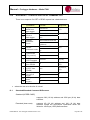
8.4
Typical instructions
TIMED GOTO
Timer controlled logging sequences
CONDITIONAL GOTO
Event controlled logging sequences
LOAD
Flexible data storage command
(BLOCK) MOVE
ACCUMULATE
OUTPUT
BLOCK CLEAR
ADDITION
SUBTRACTION
MULTIPLICATION
Block, Word and Byte move
Block summation for averaging
Control output sequences
Storage initialization
2 & 4 byte operands, 4 byte result
2 & 4 byte operands, 4 byte result
2 & 4 byte operands, 4 byte result
2 & 4 byte operands, 4 byte result
or 2 byte result & remainder
Bi-directional Data Bus read/write
DIVISION
SERIAL INPUT/OUTPUT
8.5
Buffer Control Table
Information to be recorded by the PROLOGGER is stored in one of eight memory
areas. Normally only one memory area is used and this occupies all free external
memory, starting at Address 1536 and ending at the limit of the PROLOGGER.s CMOS
memory (512k).
Unidata Manual - 7001 Prologger Hardware Issue 2.1.doc
Page 37 of 53
Manual – Prologger Hardware – Model 7001
•
For some log programs requiring lookup tables, the storage starting address may be
different.
The storage of channel data in these memory areas (buffers) is controlled by pointer
registers held in the Buffer Control Table. Both standard 16 bit and extended 32 bit
pointers are supported by Revision #32 firmware. The PROLOGGER.s LOG
instructions uses one table entry for each buffer (memory area).
An extended (32 bit, 4 byte pointers) Buffer Control Table, illustrated overleaf, is
indicated by setting bit 7 of the flag byte (BFLO) in the Buffer Control Table entry for
the appropriate buffer(s).
•
8.5.1
Standard and extended buffers can be intermixed, but only extended buffers can log
data past the 64K memory limit.
Buffer Format Convention
Information is stored in the data buffers as a sequence of one or more data bytes. Each
sequence is called a .log entry.. There may be many log entries in each buffer.
There are two log entry types:
· Fixed TIME and SIZE.
· Variable TIME and fixed SIZE.
•
Fixed TIME and SIZE
This is the most common form of log entry. Each entry is a fixed number of bytes long
and is stored at a fixed interval. For example, recording the wind speed and ambient
temperature every hour would produce fixed TIME and SIZE log entries.
Unidata Manual - 7001 Prologger Hardware Issue 2.1.doc
Page 38 of 53
Manual – Prologger Hardware – Model 7001
•
Variable TIME and Fixed SIZE
This form is used with event-initiated log entries. The first 4 bytes of the entry is the
time that the event occurred. The time bytes come from Register Address 4 to 7
followed by the log entry (if any). For example, if an event initiated log entry stored the
instantaneous value channel 1, the entry would be:
time (4 bytes), channel 1 (1 byte)
Unidata Manual - 7001 Prologger Hardware Issue 2.1.doc
Page 39 of 53
Manual – Prologger Hardware – Model 7001
9.0
PROLOGGER CONFIGURATION TABLE
The PROLOGGER has a number of operating modes for its analog inputs. During
factory calibration and testing a standard setup and some calibration factors are
permanently written into the logger.s firmware (in ROM). This part of the firmware is
referred to as the Configuration Table and a copy of it is also located in protected
memory. If a different configuration is required, you may alter parts of the table.
This chapter describes the Configuration Table and its operation.
9.1
Default Configuration Table
The PROLOGGER has a permanent (default) copy of the Configuration Table in a
ROM (Read Only Memory) chip. This default version instructs the logger to operate
with commonly used settings. A user may alter some (or all) of these default settings to
instruct the logger in another manner.
9.2
Memory Layout and Protected Memory
A small portion of the PROLOGGER memory is set aside for housekeeping functions
such as I/O buffers and the LCD Scheme Display List. This portion of memory is
protected (hidden) from normal logger operations and cannot be read or written by the
Log Program or normal GET/PUT commands.
Unidata Manual - 7001 Prologger Hardware Issue 2.1.doc
Page 40 of 53
Manual – Prologger Hardware – Model 7001
9.3
Configuration Table Layout
The Configuration Table is stored in ROM and may be read by the computer using the
S/s commands. The configuration table contains an array of 16 bit (LSB/MSB)
variables which control many aspects of the PROLOGGER’s operation (such as scan
rate). The (i)nt command is used to permanently alter settings in the configuration
table. Some settings may be viewed and adjusted from the Display/Keyboard.
A copy of the configuration table is also stored at Real Address 0 and may be read
using the protected R(ead) command. This copy is not used for PROLOGGER control,
it is available for reference only.
9.4
PROLOGGER Linear Calibration Correction
The PROLOGGER uses the following linear correction formula:y = gx + o
Where: y = corrected value.
x = raw value (from A/D converter).
g = gain coefficient.
o = offset coefficient.
The gain coefficient (g) is made up of the gain coefficients from the appropriate Gain
Drive Table gain stage entry. The same applies to the offset coefficient (o).
These coefficients represent decimal numbers (e.g. 0.15) which are stored in the
PROLOGGER in a normalised 16 bit form.
•
GAIN
The decimal gain coefficient is multiplied by 8192 to form the PROLOGGER gain
coefficient entry. That is, each bit is 1/8192 or 1.2207E-4.
g = 0.00610
g = 0.00610 * 8192 = 50 (or 32 HEX)
Gain coefficients must be POSITIVE.
Unidata Manual - 7001 Prologger Hardware Issue 2.1.doc
Page 41 of 53
Manual – Prologger Hardware – Model 7001
•
OFFSET
The decimal offset coefficient is multiplied by 8 to form the PROLOGGER offset
coefficient entry in bits. This offset must take into account the 16 bit A/D conversion as
each offset bit has a magnitude of 1/64516 of the input signal range (155mV/bit in the 5V to 5V range).
For example:
Gain stage
= 1, input range -5 to 5V
each bit
= 10,000,000/64516 = 155mV
therefore,
if O (offset)= 1.55mV on a gain of 1
= 1.55/0.155 x 8 = 80 (50 HEX)
Offset coeffiecients may be POSITIVE or NEGATIVE.
9.5
Initialisation via the RS-232
Before the PROLOGGER can be used it must be initialised. In some cases, the logger
may have stopped scanning to conserve its battery. Normally this initialisation occurs
automatically when the logger is loaded with a Scheme.
The command to initialise (or re-initialise) the logger is:
Issss
(where ssss is a 4 HEX ASCII number equal to the logger serial number)
The response from the logger following the initialisation is:
9.6
CC c/r
(where CC is the checksum error in the Configuration Table)
if CC = 00
the resident Configuration Table is valid and the logger has been
initialised to use its configuration.
if CC = 01
the resident Configuration Table is corrupted and the logger must
be returned to UNIDATA for service.
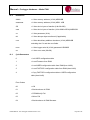
Read/Write Protected Memory
There are five RS-232 commands used with the PROLOGGER. They relate to the
maintenance and initialization of the Configuration Table. For a complete list of
STARLOG Protocol commands see Appendix B.
Unidata Manual - 7001 Prologger Hardware Issue 2.1.doc
Page 42 of 53
Manual – Prologger Hardware – Model 7001
Command
S
N
Issss
RssssBBLL
CC
Tssss
Description
Read the default copy of the Configuration
Table from ROM.
Read the logger.s serial number.
Initialize the logger with the Configuration
Table.
Read from or write to real memory Wssss
BBLLCCddddcccc (same construct as
GET/PUT but with checksum of configuration
table (cccc = MSB/LSB))
Activiate diagnostic firmware
ssss in these instructions relates to the 16 bit serial number of the PROLOGGER and
acts as a password for protected commands.
cccc is the checksum for the (W)rite command includes serial# (password), address,
size and data fields (i.e., everything except the .W. command and the checksum itself).
The .S. command does not require the serial number password as it only reads the
configuration table.
Unidata Manual - 7001 Prologger Hardware Issue 2.1.doc
Page 43 of 53
Manual – Prologger Hardware – Model 7001
10.0
TEST DIAGNOSTICS
The PROLOGGER has inbuilt diagnostic firmware activated by the protected
command:
Tssss = serial number
•
10.1
Warning: Once you select diagnostic mode, information stored in the logger may be lost.
Always unload the logger before performing test diagnostic requests and reload the
logger after diagnostics.
Diagnostic
This diagnostic offers several tasks used to test and calibrate the PROLOGGER during
manufacture. Each task corresponds to a single character sent to the logger via the
RS-232 computer interface. After receiving the Protected Command Tssss, the logger
enters Diagnostic Mode and sends the message:
‘PROLOGGER Diagnostics 7001A V33.0F’
...followed by a menu of diagnostic commands.
The diagnostic then awaits the entry of a Task Command from the host computer.
When a Task Command is received, the logger executes the Task then awaits another
Task Command (unless the previous task exited the logger from the Diagnostic Mode).
The serial number must be in hex format and entered Least Significant Byte to Most
Significant Byte. For example, the serial number 4001 is hex number 0FA7 and should
be entered using the Tssss command in the following order TA70F.
•
10.1.1
•
Warning: Diagnostic Mode is intended for technical maintenance. Certain protection
features are disabled. TAKE CARE.
Task Command List
ANALOG
A
Continuously convert and display single ended channels A0...A7.
B
Continuously convert and display single ended channels A8...A15.
F
Select differential signals.
H
Select High level signals GAIN = 1 (0.5.00.V).
I
Continuously convert and display temperature and battery readings.
L
Select Low level signals GAIN = 100 (0.50mV).
M
Select Medium level signals GAIN = 10 (0.500mV).
Unidata Manual - 7001 Prologger Hardware Issue 2.1.doc
Page 44 of 53
Manual – Prologger Hardware – Model 7001
E
•
Select Extra Low level signals GAIN = 1000 (0.5mV).
CONTROL
K
Kill (exit from) Diagnostic Mode. Resets logger.
S
Sleep. Shut down logger to conserve batteries when the logger is left
unused for long periods.
Warning: logger will be left in an uninitialized state and will not scan. The User must
reset the logger using the Issss command (or reload the logger with a valid Scheme).
•
•
•
•
•
•
COUNTER
Y
Continuously read and display four Counter channels in hertz (frequency
mode).
T
Continuously read and display four Counter channels in binary. Type any
character to stop continuous conversion mode.
INPUT/OUTPUTS
J
Display Binary inputs UIN0/UIN1.
O
Set Binary output UOT1/(LEDs), UOT0(CNTL), UOT2(ANLG).
V
Test HSIO OUT0 (pulse output).
KEYBOARD/DISPLAY
D
Test LCD display.
P
Test keyboard.
MEMORY
X
Test memory circuit.
Z
Write/Read cycle through 256 date values on RAM address 0.
R
Test RAM/ROM shadow.
MISCELLANEOUS
CR
Pressing the Enter key will end the current command (if any) and display
the Command Menu.
Esc
End the current command.
POWER SUPPLIES
U
Toggle user power supplies.
W
Toggle +5V Scan Synchronised Power supply.
Unidata Manual - 7001 Prologger Hardware Issue 2.1.doc
Page 45 of 53
Manual – Prologger Hardware – Model 7001
11.0
APPENDIX A - OPERATING ERRORS
When the PROLOGGER detects certain error conditions it sets flags in Register
Address 3.
Error flags are divided into WARNING and FATAL errors. FATAL errors cause the
PROLOGGER to stop operating and revert to sleep mode. WARNING errors are for
information only.
•
To wake a logger from sleep mode the logger must be connected to a computer and the
RTS signal presented. This powers on the logger but does not allow signal scanning or
log programs to run, however normal RS-232 communications can occur after the
prompt (*CR).
•
A logger RESET will also set the logger from ‘sleep’ to operating state.
The ERROR FLAGS are READ ONLY and cannot be reset by a log program or a (P)ut
command. These flags are only cleared when the logger is RESET (using the I
command or Keyboard RESET).
Unidata Manual - 7001 Prologger Hardware Issue 2.1.doc
Page 46 of 53
Manual – Prologger Hardware – Model 7001
12.0
APPENDIX B - PROLOGGER REVISIONS
This is a list of PROLOGGER firmware. Beside each model is a list of serial numbers
and firmware included in each logger when it was released from the factory. Features
of each revision are listed. You can use this list to determine your upgrade options.
It is possible to upgrade PROLOGGER firmware within a particular model (contact your
UNIDATA office for information).
It is not possible to upgrade firmware across different models.
Model
Firmware
Feature
7001A
Revision 33.0F
Serial No. 300
Original release.
Unidata Manual - 7001 Prologger Hardware Issue 2.1.doc
Page 47 of 53
Manual – Prologger Hardware – Model 7001
13.0
APPENDIX C - STARLOG PROTOCOL COMMAND LIST
There is no response if a GET or READ request has a bad checksum.
G
g
P
p
W
w
R
r
T
t
I
S
s
N
n
K
k
•
13.1
Command
G/get data
block from
data logger
Format
P/put data
block to
data logger
PAAAASSdd.dd
paaaaaaaassssdd.ddc
ccc
WnnnnAAAASSdd.dd
wnnnnaaaaaaaassssd
d.ddcccc
RnnnnAAAASS/r
rnnnnaaaaaaaasssscc
cc
Tnnnnzz
GAAAASS
gaaaaaaaasssscccc
W/write
protected
mode
R/read
protected mode
T/test mode
(Diagnostics)
Response
dd.ddcccc(
CR)
eecccc(CR)
eecccc(CR)
dd.ddcccc(
CR)
tnnnnzz
Initialise
CDT/Firmware
Unload CDT
from PROM
Partial Unload
of CDT from
PROM*
N/number
(serial#) of
logger
K/kill (power
down
logger)
Innnnzz
ee(CR)
S
dd.ddcccc(
CR)
sss
dd.ddcccc(
CR)
N
nnnncccc(C
R)
n
K
k
where the last ss is the size of unload.
Standard/Extended Command Differences
Standard (UPPER CASE)
supports 64K (16 bit) address and 256 byte (8 bit) data
transfers.
Extended (lower case)
supports 4G (32 bit) address and 16K (16 bit) data
transfers except the (p)ut/(w)rite commands which are
limited to 1024 byte (10 bit) data transfers.
Unidata Manual - 7001 Prologger Hardware Issue 2.1.doc
Page 48 of 53
Manual – Prologger Hardware – Model 7001
13.2
Definitions
AAAA
= 4 Hex memory address (16 bit) MSB/LSB
aaaaaaaa
= 8 Hex memory address (32 bit) MSB...LSB
SS
= 2 Hex size in bytes of transfer (8 bit 00=256)
ssss
= 4 Hex size in bytes of transfer (16 bit 0000=65536) MSB/LSB
zz
= 2 Hex parameter (8 bit)
dd
= 2 Hex data per byte transferred (if applicable)
cccc
= 4 Hex data binary addition checksum (16 bit) MSB/LSB
excluding the C/c and the cccc fields.
13.3
nnnn
= 4 Hex logger serial # (16 bit) password LSB/MSB
ee
= 2 Hex error code (00=OK)
(i)nit Parameters
0
= Init USER configuration table
1
= Load Firmware from RAM
2
= Load USER configuration table from RAM (then init00)
3
= Load FACTORY configuration table from RAM (then init02)
4
= Copy FACTORY configuration table to USER configuration
table (then init02)
Error Codes
00
= OK
01
= Bad checksum in ROM
02
= PROM/Verify Fail
03
= Mirror Fail
04
= Bad checksum in RAM firmware
Unidata Manual - 7001 Prologger Hardware Issue 2.1.doc
Page 49 of 53
Manual – Prologger Hardware – Model 7001
14.0
APPENDIX D – USING THE SDI-12 INTERFACE
14.1
Introduction
SDI-12 is an industry-originated, serial digital interface bus designed to allow
connection of a wide variety of transducers (meteorological, hydrological, water quality,
etc.) to a single SDI-12 data recorder with a single cable bus. The PROLOGGER is
such a data recorder. This means that you can, for instance, connect several SDI-12
sensors to a PROLOGGER and not have to worry about combinations of signal types
(RS-232, parallel analog, BCD, serial analog, RS-422, etc.).
A unique feature of the PROLOGGER is its ability to operate as an SDI-12 Data
Recorder or an SDI-12 Sensor.
This appendix assumes that the reader is familiar with the operation of the SDI-12
Sensor (the Sensor) and the PROLOGGER (the Recorder). For more information see
the STARLOG Programmer.s Manual, number 6201.
14.2
Theory Of Operation
When the PROLOGGER sends a .break signal., the Sensor awakes and captures the
SDI-12 command following the break signal. If the command is valid, the Sensor reads
its address setting to see whether or not its address is in fact being called, or if the
address of some other device (at another location) is being sought. If the logger is
looking for a different address, the Sensor will go back to sleep until another break
signal is received.
If the address being sent belongs to the Sensor, it will scan the instructions coming
from the logger to see what action is required. The two most important commands at
this time are:
Measure:
If the Sensor receives the START MEASUREMENT command, it will report back
to the logger the number of parameters enabled for measurement, and that these
parameters are available to be sent to the logger immediately.
Data:
If the Sensor receives the SEND DATA command, it will send the last parameter
readings measured to the PROLOGGER for storage.
14.3
Master Mode (SDI-12 Data Rcorder)
Using the PROLOGGER as an SDI-12 Data Recorder allows several PROLOGGERs
to be connected together.
14.3.1
SDI-12 Data Recorder Commands
Two Scheme Program instructions are used to control the SDI-12 Master operation:
SDIGET
which collects measurements from the nominated SDI-12,m
sensor, and
SDICONV
which converts the collected data for use by the Log Program.
Unidata Manual - 7001 Prologger Hardware Issue 2.1.doc
Page 50 of 53
Manual – Prologger Hardware – Model 7001
Measurements may be converted into fixed point Short Integers (for manipulation by
the Scheme), Floating Point Numbers (for logging by the Scheme) or an ASCII string.
· Integers are two bytes.
· Floating Point numbers are 4 bytes.
· An ASCII string is zero byte terminated.
14.4
Data Recorder Coordination
Once an SDI-12 communication has commenced (SDIGET instruction executed) the
SDI-12 Bus is busy and will ignore any subsequent SDIGET commands until the active
measurement transfer is complete. The measurements are stored in memory, to be
converted by a SDICONV instruction. Converted measurements (stored on
PROLOGGER channels) may be further processed by the Scheme program and
logged.
Because most SDI-12 sensors require considerable time to make their measurements
(typically 60 seconds), the PROLOGGER remains powered up awaiting a response
from the sensor. This mode of operation usually requires the Scheme Program to
initiate SDI-12 Measurements (SDIGETs) prior to the desired Log Interval.
The sequencing of the SDI-12 measurements is under the control of the Scheme
Program (which is defined during Scheme Editing.) (See Chapter 7 in the STARLOG
Version 3 Software Manual No. 6245.)
14.4.1
Measurement Errors
If an error occurs during a data collection sequence (SDIGET), the sequence is retried
a total of 10 times (configurable). A non-recoverable error causes the SDIGET
instruction to report a .null. result and a subsequent SDICONV will not return any data
(the channel readings remain unchanged from their last good reading).
14.4.2
Transparent Mode (Extended Commands)
The PROLOGGER supports a transparent mode of operation that allows ad-hoc
commands from an external computer (or modem) to be sent to SDI-12 sensors
connected to the SDI-12 bus.
This mode is entered using the STARLOG protected command:
tssss01
Extended commands may be issued while the Scheme Program is operating, but
remember that the extended commands may disrupt the Scheme Program data
collection timing. Type
Alt+T
from within the Communications window to enter this mode.
Unidata Manual - 7001 Prologger Hardware Issue 2.1.doc
Page 51 of 53
Manual – Prologger Hardware – Model 7001
14.4.3
SDI-12 Test
To check the operation of the SDI-12 system the following sequence can be tested.
Configure the PROLOGGER as SDI-12 Data Recorder to enable SDI-12 operation. At
address 384 (Log Program) insert these instructions:
128
129
128
0
0
1
0
255
100
0
4
SDIGET
0
SDICONV
0
SDIGET
BUSY:EXIT
BUSY
INTEGER,100
ADDR0
This sequence will branch to BUSY whilst SDI-12 bus is busy . then convert the
previous measurement to 16 bit integers stored into addr 100 . then issue an SDI-12
measurement sequence to the Sensor at SDI-12 address 0.
14.4.4
Interrogation Mode (SDI-12 Sensor)
Using the PROLOGGER as an SDI-12 Sensor enables it to be interrogated by another
PROLOGGER (or any SDI-12 Recorder). The SLAVE PROLOGGERs do not record
their measurements (although they could do so) but instead, send the computed results
to the MASTER PROLOGGER for logging. The PROLOGGER will continue to operate
at its pre-set scan rate and will perform all the normal logging functions.
STARLOG measurements, RS-232 communications and data logging, co-exist with
SDI-12 interrogation.
Whenever an SDI-12 Data Recorder issues a START MEASUREMENT/ SEND DATA
sequence, the PROLOGGER immediately responds with the latest parameter readings.
•
14.4.5
In this mode, the SDI-12 command START MEASUREMENT does not initiate a new
measurement cycle and the data is always valid and available for immediate retrieval by
the Data Recorder.
Changing the PROLOGGER Address
Address 0 is the default address setting for SDI-12; each PROLOGGER is shipped set
to address 0.
Unidata Manual - 7001 Prologger Hardware Issue 2.1.doc
Page 52 of 53
Manual – Prologger Hardware – Model 7001
14.5
PROLOGGER SDI-12 Implementation
14.5.1
Default Settings
address = 0
retry = 10
# of channels = 2
SDI0 channel 1 address = 200
A0
SDI1 channel 2 address = 202
A1
SDI2 channel 3 address = 204
A2
SDI3 channel 4 address = 206
A3
SDI4 channel 5 address = 208
A4
ID string = 011UNIDATA 7001A 2200000<CR><LF>
VERIFY string = 00000<CR><LF>
START string = 00002<CR><LF>
14.5.2
Altering SDI-12 Settings
Change the PROLOGGER Configuration Setting (see Appendix D of the STARLOG
Version 3 Software Manual #6245) to adjust SDI-12 settings in the PROLOGGER.s
Configuration Table. Adjustments are:
address = 0…9
retry count =1…25
# of channels = 0…5
channel 0.4addr = n (location of 16 bit channel in the PROLOGGER Register Block)
Unidata Manual - 7001 Prologger Hardware Issue 2.1.doc
Page 53 of 53